Embed Size (px)
Citation preview

International Journal of Computer Science and Applications, Technomathematics Research Foundation Vol. 6, No, 4, pp 63 - 83 , 2009
63
THE FEATURE ORIENTED REUSE METHOD WITH BUSINESS
COMPONENT SEMANTICS
Marcel Fouda Ndjodo The University of Yaounde I
National Higher Teacher’s Training College Department of Computer Science and Educational Technology
P.O. Box 47 Yaoundé - Cameroon [email protected]
Amougou Ngoumou
The University of Douala The University Institute of Technology
Department of Computer Science P.0. Box 8698 Douala - Cameroon
Abstract
FORM, which was developed at Pohand University of Science and Technology (POSTECH) in South Korea, is a systematic method that looks for and captures commonalities and variabilities of a product line in terms of “features”. The results of the analysis are used to develop reusable product line assets (architectures and components). This method includes techniques and tools for product line engineering but has a loose structure since it does not provide guidance to reuse and rigorously analyze its assets. This paper extends the semantic of FORM assets in order to specify conceptual reusable business components in FORM. For this purpose, we used the model proposed by Ramadour, which introduces the notion of “context” to guide conception and reuse of business components. The Z notation is used to provide a framework for rigorous analysis of the reusable business components produced.
Keywords: product line engineering, feature-orientation, domain analysis, business components, reuse.
1 Introduction
Nowadays, research in software reuse concerns conceptual components design and exploitation allowing domain knowledge and reasoning approach reuse [1]. A key idea in software reuse is domain engineering (or product line engineering). The basic insight is that most software systems are not new. Rather they are variants of systems that have already been built. Most organizations build software systems within a few business lines, called domains, repeatedly building systems variants within those domains. This

Ndjodo & Ngoumou
64
insight can be leveraged to improve the quality and productivity of the software production process [2].
Several product line engineering approaches exist: The Family-Oriented Abstraction, Specification, and Translation method, FAST [3], the Domain Analysis and Reuse Environment, DARE [4], The Komponentbasierte Anwendungsentwicklung, KobrA [5], The c[K]omponent Organizer and linking Assistant, Koala[6], the Product Line UML-Based Software Engineering, PLUS [7], and the Feature Oriented Reuse Method, FORM [8].
FORM product line engineering consists of two major processes [9]: asset development and product development. Asset development consists of analyzing a product line - such as marketing and product plan (MPP) development and refinement, feature modeling, and requirement analysis - and developing architectures and reusable components based on analysis results. Product development includes analyzing requirements, selecting features, selecting and adopting architecture, adapting components and generating code for the product. In this work, we add contextual information to the FORM’s assets and we define a reusable business assets database in order to improve the reusability of the assets. We named the new approach FORM with business component semantics (FORM/BCS).
More generally, the main contributions of this paper are a) the incorporation of contextual information in FORM assets in order to improve their reusability, b) the breakdown of the linearity of the FORM engineering process, c) the definition of a business component database supporting requests and d) the definition of a vertical engineering process allowing to refine high level components to low level concrete components.
The rest of the paper is organized as follows: Section 2 overviews FORM. Section 3 presents the Ramadour’s business component model [10]. Our conceptual framework is given in section 4. Section 5 defines FORM/BCS reusable components. Section 6 presents the FORM/BCS engineering process. Finally, the conclusion presents possible further research domains in our work continuation.
2 Overview of the Feature Oriented Reuse Method
FORM (Feature-Oriented Reuse Method) is a systematic method that looks for and captures commonalties and differences of applications in a domain in terms of "features" and using the analysis results to develop domain architectures (conceptual architecture, process architecture and module architecture) and business components (For more insight of business components, see [11, 12, 13, 14]). The model that captures the commonalties and differences is called the “feature model” and it is used to support both engineering of reusable domain artifacts and development of applications using the domain artifacts. Once a domain is described and explained in terms of common and different “units” of computation, they are used to construct different “feasible” configurations of reusable architectures.
A feature model consists of: A feature diagram, which is a graphical AND/OR hierarchy of features, that
captures logical structural relationships (e.g. composition and generalization) among features. Three types of relationships are represented in this diagram: “composed-of”, “generalization/specialization”, and “implemented-by”. Features themselves may be “mandatory” (unless specified otherwise), “optional” (denoted with a circle), or “alternative” (denoted with an arc).

The Future Oriented Reuse Method
65
Composition rules that supplement the feature diagram with mutual dependency and mutual exclusion relationships (This is used to verify the consistency and completeness of the selected features).
Issues and decisions that record various trade-offs, rationale, and justifications for feature selection.
A conceptual architecture describes a system in terms of abstract, high level components and relationships between them.
A process architecture represents a concurrency structure in terms of concurrent process (or task) to which functional elements are allocated; the deployment architecture shows an allocation of processes to hardware resources.
A module architecture is a module hierarchy which largely corresponds to the feature hierarchy. Also, alternative features may be implemented as a template module or a higher level module with an interface that could hide all different alternatives. This way, a module may be associated with a set of relevant features. Here, reusable components (or modules) are obtained through the refinement of the process and deployment architectures using the design object model.
The FORM engineering process is pictured in the following figure:
DomainAnalysis
Reference Architecture
Developmement
Reusable Component
Development
FORM Domain Engineering
Process
Product
Feedback for updating the Domain Model
Model Reuse
Legend:
Feature Model
Reference Architecture
Reusable Component
Userrequirements
analysis
ApplicationArchitecture
Selection
ApplicationSoftware
Development
FORM Application Engineering
Application Architecture
Process
Mod
el
Mod
ule
Mod
el
Sub
system
Mod
el
Feature Selection
Specification
Application Software
Fig. 1. FORM Engineering Process
For more insight of FORM, see [8, 9, 15, 16].
3 Overview of the Ramadour’s reusable business component Model
Among the most important contributions added by Ramadour in the semantic of business components we have the integration of contextual information. According to the model proposed, a reusable business component is a conceptual modeling problem in a product line with a solution adapted to a particular context [10]. The specification of business components includes two parts: the specification of the product and the specification of the process. The first part provides a fragment of the conceptual diagram or engineering method; the second describes the process which sustains the product part reuse.
Formally, a business component is a triple of the form <Name, Descriptor, Realization>. It is graphically represented as a compartmented box. The upper section contains descriptor elements; the lower section presents the solution and its adaptation points.

Ndjodo & Ngoumou
66
Name
IntentionDomainProcess
Descriptor Context
RulesSolutionRealization Adaptation points
Fig. 2. Business component structure
3.1 Descriptors
A descriptor, which is a couple <Intention, Context>, presents a conceptual modeling problem to be solved in a particular context. This problem can be the decomposition of a system, an activity organization or an object description. Goals, activities and objects concerned are carried on an application field and/or an engineering method. The descriptor is then the visible section of the component which guides its reuse since it points out in which situation the component can and must be used. The descriptor gives an answer to the following question: “when and why use this component?”
3.1.1 Intentions
An intention is the expression of a generic modeling problem. The term “generic” here means that this problem does not refer to the context in which it is supposed to be solved. For instance, the intention “to describe the object book” can be realized in different domains: library management, bookshop management, etc. Of course, in those different contexts, this same problem has different solutions. At the reuse moment, the intention is used to research components corresponding to a conceptual modeling problem. An intention is structured as an action applied to a target object. It is represented as follows:
((verb)ACTION(name)TARGET)INTENTION
For instance, "((describe)ACTION(the object "book")TARGET)INTENTION" is an intention for which “describe” is the action and “book” is the object.
In reference to Domain models [10], we have three types of intentions: system decomposition, activity organization and object description.
Reusable knowledge types Intentions on those knowledge domain goal ((decompose)ACTION domain activity ((organize)ACTION domain object ((describe)ACTION
Fig. 3. Types of intentions
3.1.2 Contexts
A context is the domain knowledge which explains the choice of one alternative and not another. The context part provides elements which separate different solutions realizing the same intention. Contexts are specified in the following format:
(((verb)ACTION(object)TARGET[(phrase)PRECISION])DOMAIN
((verb)ACTION(object) TARGET [(phrase)PRECISION])PROCESS*
The Future Oriented Reuse Method
67
((verb)ACTION (object) TARGET [(phrase)PRECISION]RULE*)CONTEXT
We use brackets to point out optional elements. Example: The specification below describes the context of a library where one has to manage copies of books. It therefore suggests a conceptual solution having the classes “book” and “copy”.
"(((manage)ACTION (a library)TARGET)DOMAIN
((manage)ACTION (the stock)TARGET)PROCESS
((manage)ACTION (copies of a same book)TARGET)RULE)CONTEXT" 3.2 Realizations
The realization section of a reusable component provides a solution to the modeling problem expressed in the descriptor section of the component. It is a conceptual diagram or an engineering method fragment in the form of system decomposition, an activity organization or an object description. The goals, the activities and the objects figuring in the realization section concern the application field (product fragment) or the engineering process (process fragment).
The solution subsection, which is the reusable part of the component, provides a product or a process fragment. This solution may have adaptation points whose values are fixed at the reuse moment. Adaptation points enable the introduction of parameters in the solutions provided by reusable components. Those parameters are values or values domain of an element of the solution.
In this article, we extend the semantic of FORM assets to integrate contextual information (or business component semantics) in their description using Ramadour’s vision. For more insight of the notion of context, see [10, 17, 18, 19].
4 The Conceptual framework This section defines the FORM semantics of the main concepts of the Ramadour’s framework for the design and specification of business process components [10]. These concepts are: “solution”, “intention”, “domain”, “process”, “rule”, “context”, “descriptor”, and “realization”. This semantics will be used in the next section to redefine the FORM’s product line assets.
We use the Z formal specification language [20] because it lays down the foundation for a rigorous analysis of the method assets and the UML modeling concepts specified by OMG [21] since they are able to support product line engineering. Mainly we will use the UML types Attribute, Operation, Action and universal types like Boolean and Text which will be considered as basic.
4.1 Solutions
In FORM, the Ramadour’s solutions are the product line reusable assets described in section 2 above. That is, a solution is either a feature model, or a reference architecture, or a conceptual architecture, or a process architecture, or a module. The type Solution below enables to formally describe solutions.

Ndjodo & Ngoumou
68
Solution == Feature ConceptualArchitecture ProcessArchitecture Module ReferenceArchitecture Text
Features
In FORM, a feature is a property visible by users and application developpers of the domain. Features are classified in two groups: generic features (or services) and contextual features. Generic features are those of the capacity level of the domain. This means that a generic feature literally marks a distinct service, operation or function. Contextual features however are those of the operating environment, the domain technology and the implementation techniques. Performances of a system are non fonctional features which are also classified in that second group.
In FORM, a feature model of a domain gives the “intention” of that domain. This is why feature models are made only with generic features. In order to formalize this concept, we consider that a generic feature is an activity caused by an event which is applied to a target objects set. Features have generalization and decomposition. A feature’s decomposition has three kinds of disjoint subcomponents:
1) The set of common features which indicate reuse opportunity, 2) The set of optional features; 3) The set of groups of alternate features.
Hence, we capture features by the following schema:
Feature = =[verb: Activity ; objects: Target ; decomposition:[common: iseq Feature; optional: iseq Feature; variabilities: iseq iseq Feature] generalization: iseq Feature f : Feature, optional(decomposition(f)) common(decomposition(f)) = f : Feature, ( (V variabilities(decomposition(f))) common(decomposition(f)) = f: Feature, optional(decomposition(f)) ((V variabilities(decomposition(f)))) = f : Feature , V1, V2 variabilities(decomposition(f)), V1 V2 = f : Feature , (common(decomposition(f)) optional(decomposition(f)) ( (V variabilities(decomposition(f))))) generalization(f) = ]
Activity == [common: iseq Task ; optional: iseq Task; variabilities: iseq iseq Task a : Activity, optional(a) common(a) = a : Activity, ( (V variabilities(a))) common(a) = a : Activity, optional(a) ((V variabilities(a))) = a : Activity, V1, V2 variabilities(a), V1 V2 = ]
Task == [common : iseq Action ; optional: iseq Action; variabilities: iseq iseq Action; is_transient: Boolean
The Future Oriented Reuse Method
69
t : Task, optional(t) common(t) = t : Task, ( (V variabilities(t))) common(t) = t : Task, optional(t) ((V variabilities(t))) = t : Task, V1, V2 variabilities(t), V1 V2 = ]
Target = iseq Class Class = = [name : Text
attributs : iseq Attribut operations : iseq Operation| ]
When the context is clear, we write: common(f) for common(decomposition(f))
optional(f) for optional(decomposition(f)) variabilities(f) for variabilities(decomposition(f)); decomposition(f) for common(f) optional(f) ((V variabilities(t)))
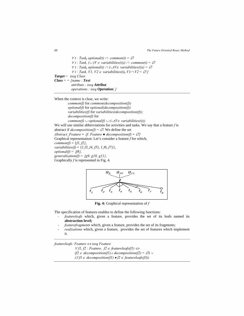
We will use similar abbreviations for activities and tasks. We say that a feature f is abstract if decomposition(f) = . We define the set Abstract_Feature = {f: Feature ● decomposition(f) = } Graphical representation: Let’s consider a feature f for which, common(f) = {f1, f2}, variabilities(f) = {{ f3, f4, f5}, { f6, f7}}, optional(f) = {f8}, generalization(f) = {g9, g10, g11}. Graphically f is represented in Fig. 4.
Fig. 4: Graphical representation of f The specification of features enables to define the following functions:
- featureleafs which, given a feature, provides the set of its leafs named its abstraction level;
- featurefragments which, given a feature, provides the set of its fragments; - realizations which, given a feature, provides the set of features which implement
it.
featureleafs: Feature iseq Feature f1, f2 : Feature, f2 featureleafs(f1) (f2 decomposition(f1) decomposition(f2) = ) ( f3 decomposition(f1) f2 featureleafs(f3))
f
g9 g10 g11
f1 f2 f3 f4 f5 f6 f7 f8

Ndjodo & Ngoumou
70
featurefragments: Feature iseq Feature f1, f2 : Feature, f2 featurefragments(f1) (f2 decomposition(f1) ( f3 decomposition(f1) f2 featurefragments(f3))
realizations: Feature iseq Feature f1, f2 : Feature, f2 realizations( f1) common(f1)) common(f2) V variabilities(f1), ( g common(f2) g V) optional(f1) optional(f2)
We define instantiations of abstract features as follows:
_instantiates_ : Abstract_Feature Feature f1, f2 : Feature f2 instantiates f1
verb(f1) = verb(f2) objects(f1) = objects(f2) decomposition(f2) ≠
We say that two features are functionally equivalent if they have the same verbs, the same target objects set, and the same decomposition and generalization.
_equivalent_ : Feature Feature f1, f2 : Feature f2 equivalent f1
objects(f2) = objects(f1) decomposition(f2) = decomposition(f1) generalization(f2) = generalization(f1)
Two features can collaborate if the intersection of their target objects set is not
empty.
_collaborates_ : Feature Feature f1, f2 : Feature f2 collaborates f1 objects(f2) objects(f1) ≠
Conceptual architectures
A conceptual architecture is a set of subsystems and links. The intersection of features objects in a same subsystem is not empty. A link establishes a relation between different subsystems.
ConceptualArchitecture = = [subsystems: iseq SubSystem ; links :P SubSystem x SubSystem ca : ConceptualArchitecture , ss subsystems(ca), f1, f2:Feature, f1, f2 ss f2 collaborates f1; ca ConceptualArchitecture, ss1,ss2 subsystems(ca),

The Future Oriented Reuse Method
71
(ss1, ss2) links(ca) f ss1, g ss2 decomposition(f) decomposition(g) ≠ ]
SubSystem = iseq Feature
In the above specification, P denotes the subset of a set in the Z notation.
This model conducts to the definition of the following function: conceptualarchitectures which, given a feature, provides its conceptual architectures set.
conceptualarchitectures: Feature iseq ConceptualArchitecture
Thus, we specify properties sustaining conceptual architectures of a feature.
f : Feature, ca: ConceptualArchitecture, ca conceptualarchitectures(f) r realizations(f) (s subsystems(ca)) = decomposition(r) f : Feature, ca conceptualarchitectures(f), (ss1,ss2) links(ca) ss1ss2
There is an implementation function named SsImplement between subsystems.
SsImplement : SubSystem iseq SubSystem ss1, ss2 : SubSystem ss2 SsImplement (ss1)
f ss1, g ss2 g realizations(f)
Process architectures
A process architecture consists of a set of processes, a set of inter-processes messages, a set of objects (or class instances), and data access mechanisms.
ProcessArchitecture = = [process: iseq Task ; messages: iseq [tasks: (Task U {null}, Task U {null});
body: Text; without_reply: Boolean ] dataaccess: iseq [ access: (Task, Class); body:
Text] class : iseq Class
pa : ProcessArchitecture, m messages(pa), (1) tasks(m) (null, null) (2) (t, null) = tasks(m) t process(pa) (3) (null, t) = tasks(m) t process(pa) (4) (t1, t2) = tasks(m) (t1, t2) process(pa) x
process(pa) pa : ProcessArchitecture, d dataaccess(pa),
(t, c) = access(d) t process(pa) c class(pa) ]
The function processarchitectures bellow characterizes process architectures
obtained from a subsystem since process architecture are built from subsystems.

Ndjodo & Ngoumou
72
processarchitectures: SubSystem iseq ProcessArchitecture ss: SubSystem, pa: ProcessArchitecture, pa processarchitectures(ss) t process(pa), f ss t decomposition(verb(f)) (t1, t2) messages(pa) decomposition(t1) decomposition(t2) ≠ (t, c) dataaccess(pa) f ss (t decomposition(verb(f)) c objects(f)) c class(pa) f ss c objects(f).
The function PImplement below, which gives the tasks realizing a given task, can be used to link the processes of a process architecture.
PImplement : Task iseq Task t1, t2 : Task t2 PImplement (t1)
common(t1) common(t2) V variabilities(t1), ( g common(t2) g V) optional(t1) optional(t2)
Modules A module is characterised by its name, parameters, its description and its real implemented code.
Module = =[name : Text ; parameters: iseq [label: Text ; type: Text]; desc: [task: Task; included: iseq Module; required: iseq Module] implementation : Text (1) m1, m2: Module, m2 included(desc(m1)) name(m2) actions( task(desc(m1))) implementation(m2) “”; (2) m1, m2: Module, m2 required(desc(m1)) name(m2) actions(task(desc(m1))) implementation(m2) = “”; (3) m: Module, actions(task(desc(m))) = ( actions(task(desc(m2 included(desc(m)))))) ( actions(task(desc(m3 required(desc(m)))))) ]
Modules are built from processes or tasks. The function modules bellow
characterizes modules obtained from a process.
module: Task Module t: Task, m: Module, m = module(t) task(desc(m)) = t
The following function ModuleImplement for which, given a module provides a set of modules which realize it, enables to link modules.

The Future Oriented Reuse Method
73
ModuleImplement : Module iseq Module m1, m2 : Module m2 ModuleImplement (m1) task(desc(m2))
PImplement(task(desc(m1)))
Reference architecture A reference architecture consist of a conceptual architecture, a set of process architectures and a set of modules.
ReferenceArchitecture = = [conceptualarchitecture: ConceptualArchitecture; processarchitectures: iseq ProcessArchitecture; modules: iseq Module]
4.2 Intentions
To capture intentions in FORM product line assets rewriting, we use the Intention schema.
Intention = = [action: Activity; target: Interest]
Interest = Domain iseq Class
4.3 Domains
In the new presentation of FORM product line assets, we want to explicitly bring out the concerned domain; that is why we introduce a Domain schema witch helps to meet this goal.
Domain = = [action: Activity; target : iseq Class ; precision : Text]
4.4 Processes
The process concept enables to bring out a process hidden in a model, to integrate it in the new FORM product line assets presentation, we define a process schema.
Process = = [action: Activity; target: iseq Class; precision: Text ]
4.5 Rules To express conditions witch must be satisfied to realize an action on a target, we incorporate rules in assets through the Rule schema.

Ndjodo & Ngoumou
74
Rule = = [action : Task ; target : iseq Class ; precision : Text]
4.6 Contexts
A context represents a combined domain with its process and rules. We capture it in our assets with the Context schema.
Context = = [domain :Domain ; prosess : iseq Process ; rules : iseq Rule c: Context, action(domain(c)) = {action(pprocess(c))} target(domain(c)) ((target( p process(c)))) = (decomposition(action( p process(c)))) = {action(r rules(c))} ]
There are refinement or inclusion relations between contexts belonging to the same domain. These refinement relations are clarified through the refine relation.
_refine_ : Context Context C1, C2 : Context C2 refine C1
If (process(C1) = {} rules(C1) = {}) Then (domain(C1) = domain(C2) process(C2) {} rules(C2) {}); If (process(C1) {} rules(C1) = {}) Then (domain(C1) = domain(C2) process(C1) process(C2) rules(C2) {}); If (process(C1) {} rules(C1) {}) Then (domain(C1) = domain(C2) process(C1) process(C2) rules(C1) rules(C1) ).
4.7 Descriptors
An intention expressed in a context constitutes a descriptor. This concept is captured in our assets by the following schema:
Descriptor = = [intention : Intention ; context : Context d : Descritor,( target(intention(d)) = domain(context(d))) (intention(d) = processus(context(d)))]
4.8 Realizations
A solution combined with its adaptation points constitutes a realization. In our assets we capture them by the following schemas:
FeatureRealization = = [solution: Feature ; adaptationpoints : iseq {(Feature, iseq Feature)}

The Future Oriented Reuse Method
75
fr: FeatureRealization, (f, V) adaptationpoints(fr) f featurefragments(solution(fr)) V = realizations(f) ]
ConceptualRealization = = [solution: ConceptualArchitecture ; adaptationpoints : iseq {(SubSystem, iseq SubSystem)} cr: ConceptualRealization, (ss, V) adaptationpoints(cr) ss subsystems(solution(cr)) V = SsImplement(ss)]
ProcessRealization = = [solution: ProcessArchitecture ; adaptationpoints : iseq {(Task, iseq Task)} pr: ProcessRealization, (t, V) adaptationpoints(pr) t process(solution(pr)) V = PImplement(t)]
ModuleRealization = = [solution: Module; adaptationpoints : iseq {(Module, iseq Module)} mr: ModuleRealization, (m, V) adaptationpoints(mr) m required(desc(solution(mr))) V = ModuleImplement(m)]
ReferenceRealization = = [solution: ReferenceArchitecture ; adaptationpoints : iseq {(SubSystem, iseq SubSystem)} iseq {(Task, iseq Task)} iseq {(Module, iseq Module)} ra: ReferenceArchitecture, (ap, V) adaptationpoints(ra) (ap, V) adaptationpoints(conceptualarchitecture(ra)) adaptationpoints(pa processarchitectures(ra)) adaptationpoints(m modules(ra))]
ReusableComponentRealization = = [solution: Text; adaptationpoints : Text]
Realization = FeatureRealization ConceptualRealization ProcessRealization ModuleRealization ReferenceRealizationReusableComponentRealization
5 The FORM/BCS reusable components. This section defines the reusable business components of FORM/BCS. These components are formalized through the following Z schema:
ReusableBusinessComponent = = [name: Text; descriptor: Descriptor realization: Realization]
5.1 Feature business components
FORM’s features are now viewed as reusable business components characterized by a name, a descriptor and a realization witch is forcedly a feature realization. The following abstract type enables to capture a feature business component.
FeatureBusinessComponent = = [name :Text ; descriptor: Descriptor;

Ndjodo & Ngoumou
76
realization: FeatureRealization fbc: FeatureBusinessComponent, action(domain(context(descriptor(fbc)))) = verb(solution(realization(fbc))) target(domain(context(descriptor(fbc)))) = objects(solution(realization(fbc))) g decomposition(solution(realization(fbc))), p process(context(descriptor(fbc))) verb(g) = action(p) objects(g) = target(p) h decomposition(g decomposition(solution(realization(cdc)))), p process(context(descriptor(cdc))) verb(h) = action(p) objects(h) = target(p) ]
Example: The following business component skeleton defines the Cameroonian Computerized System for the Integrated Management of State Personnel and Salaries managed by the Ministry of Public Service, which is currently reengineered in order to improve its maintainability through the use of business components.
Name: Functional Model of the Integrated Management of Civil Servants and Salaries in Cameroon
Descriptor : Intention : (Define)ACTION ((manage)ACTION ( civil servants and salaries)TARGET)TARGET
Context : Domain : f = (manage)ACTION (civil servants and salaries)TARGET
Process : f1 = (manage)ACTION (careers)CIBLE f2 = (manage)ACTION (payroll)CIBLE f3 = (manage)ACTION (training)CIBLE
f4 = (manage)ACTION (inter-ministerial network)CIBLE
f5 = (administer)ACTION (the system)CIBLE
f6 = (manage)ACTION (mail)CIBLE
/* sub-processes of f1 */ f11= (manage)ACTION (recruitment)TARGET
f12= (manage)ACTION (promotion)TARGET
f13= (manage)ACTION (position)TARGET
/* sub-processes of f4 */ f41= (use)ACTION (optic fiber network)TARGET
f42 = (use)ACTION (radio network)TARGET
f43 = (use)ACTION (twisted pair network)TARGET
/* sub-processes of f5 */ f51 = (manage)ACTION (users)TARGET
f52 = (manage)ACTION (profiles, users)TARGET
f53 = (manage)ACTION (the audit track, users)TARGET
Rules : /* some rules of the process f11 */

The Future Oriented Reuse Method
77
f111 = (integrate)ACTION (civil servant)TARGET (if he has passed competitive examination or he has a diploma giving right to integration)PRECISION
f112 = (sign recruitment order)ACTION (civil servant)TARGET (if the prime minister office has authorized)PRECISION
etc… Realization :
Solution : f
f1 f3 f5
f11 f12 f13f51 f52 f53
f111 f112
f2 f4
f41 f42 f43
f6
Adaptation Points: {(f, realizations (f), (f4, realizations (f4))}
End. 5.2 Reference architecture business components A reference architecture business component is a reusable business component in which the realization is a reference realization.
ReferenceArchitectureBusinessComponent = = [name : Text ; descriptor: Descriptor; realization: ReferenceRealization rabc: ReferenceArchitectureBusinessComponent, ss subsystems(conceptualarchitecture(solution(realization(rabc)))), f ss, p process(context(descriptor(rabc))) verb(f) = action(p) objects(f) = target(p); rabc: ReferenceArchitectureBusinessComponent, (ss1, ss2) links(conceptualarchitecture(solution(realization(rabc)))), f1 ss1, f2 ss2, g decomposition(f1) decomposition(f2), p process(context(descriptor(rabc))) action(p) = verb(g) target(p) = objects(g) rabc: ReferenceArchitectureBusinessComponent, t process(pa processarchitecture( solution(realization(rabc)))), r rules(context(descriptor(rabc))) t = action(r); rabc: ReferenceArchitectureBusinessComponent, c class(pa processarchitecture(solution(realization(rabc)))), r rules(context(descriptor(rabc))) c target(r); rabc: ReferenceArchitectureBusinessComponent, (t1, t2) messages(pa processarchitecture( solution(realization(rabc)))) decomposition(t1)

Ndjodo & Ngoumou
78
decomposition(t2) ≠ ; rabc: ReferenceArchitectureBusinessComponent, (t, c) dataaccess(pa processarchitecture(solution(realization(rabc)))) r rules(context(descriptor(rabc))) action(r) decomposition(t) c target(r) rabc: ReferenceArchitectureBusinessComponent, t = task(desc(m modules(solution(realization(rabc))))) p process(context(descriptor(rabc))) ● t = action(p)]
5.3 Reusable component A reusable component is a reusable business component in which the realization is a reusable component realization.
ReusableComponent = = [name: Text ; descriptor: Descriptor; realization: ReusableComponentRealization ]
5.4 Reusable business components databases
The rewriting of the FORM product line assets has been realized through: - Establishing a correspondence between the solution part of the reusable
business component model formalized by Ramadour and FORM product line assets;
- Adding new information to FORM product line assets, notably the intention, the domain, the process, rules and adaptation points.
This wealth added to each FORM product line asset has conducted to think the storage of rewritten assets in a request components database.
For reuse purposes, the different assets of the FORM/BCS method can be stored in a reusable business components database which can be requested using operators developed by Ramadour[10]: search operators, selection operators, adaptation operators and composition operators. Formally, we specify this component database by the following schema:
ComponentsDatabase = = [FeaturesBusinessComponents : iseq FeaturesBusinessComponent;ReferenceArchitectureBusinessComponents : iseq ReferenceArchitectureBusinessComponent; ReusableComponents : iseq ReusableComponent ]
6 The FORM/BCS engineering process
The FORM/BCS method, as FORM, consists of two engineering processes: an Horizontal Engineering Process driven by the FORM’s domain engineering process and a Vertical Engineering Process driven by the FORM’s application engineering process. The vertical engineering process allows the refinement of high level components to low level concrete components. The process can then be repeated at each abstraction level and

The Future Oriented Reuse Method
79
the number of reusable components produced at each level is the same. The FORM/BCS engineering process is therefore pictured as follows:
SpecificSoftware
ApplicationDomain Specific
featurebusiness
component
Specificarchitecture
businesscomponent
Specificrequirements
analysis
Specific architecture
design
Specificsoftware
development
Domain Component Database
Reusable featurebusiness component
database
Reusable componentdatabase
Reusable referencearchitecture businesscomponent database
Specific Domain Component Database
Reusable specific feature business
component database
Reusable specificsoftware database
Reusable specificarchitecture businesscomponent database
ReusableComponent
DomainFeature
BusinessComponent
ReferenceArchitecture
BusinessComponent
DomainAnalysis
Reference ArchitectureBusiness Component
Design
ModuleBusiness
ComponentDevelopment
SelectedFeature
BusinessComponent
Selected ReferenceArchitecture Business
Component
SelectedReusable
Component
Horizontal Engineering Process
Vertical E
ngin
eering P
rocess
Database
Activity
Component storage
Component reuse
Legend:
Domain refinement
Fig. 5: FORM/BCS Engineering Process
6.1 The Horizontal Engineering process
The aim of the Horizontal Engineering process is to analyze a domain in order to produce the reusable business components of that domain which consist of (i) the feature business component, (ii) the conceptual business component, (iii) the process business component, and (iv) the module business component.
The horizontal engineering process has three independent activities: the domain analysis activity, the design activity and the development activity.
1) Given a domain, the domain analysis activity, which is intuitive, produces a feature business component for that domain. This feature model, defined in section 5.1, is stored in a feature business component database.
2) Given a feature business component selected in the database of reusable feature business components, the design activity produces a reference architecture business component, defined in section 5.2, which is stored in a database of reusable reference architecture business components.
3) Given a reference architecture business component, the development activity produces a set of reusable components. These reusable components, defined in section 5.3, are store in a database of reusable components.

Ndjodo & Ngoumou
80
The following properties of the FORM/BCS Domain Analysis process described above can be considered as the main improvements of the original FORM’s Domain Analysis process:
- Reusable assets integrate context: information about assets reuse in the form of context is integrated in assets.
- The implementation of the activities in the new method is not linear: That is, they can be perform in any order. The assets produced by activities of the method are stored in a database of reusable assets which can be requested using operators for reuse developed by Ramadour[10]: search operators, selection operators, adaptation operators and composition operators.
- A business component database is added: For the storage of assets, a reusable business component database is structured. This database enables engineering for reuse through the storage of assets and engineering by reuse through requests which can be submitted to it using operators for reuse listed under.
6.2 The Vertical Engineering process
The aim of the Vertical Engineering process is to derive a Domain Component Database of an application domain of a domain which already has a database of reusable domain components.
The Vertical Engineering process has three independent activities: the specific requirements analysis, the specific architecture design and the specific software development.
1) Given an application domain A of a domain D and a feature business component F of D, the aim of the specific requirements analysis of the domain A is to derive a feature business component F' of A from F. For this, the activity operates choices in F to reduce the number of optional features or groups of alternatives features contained in the decomposition of its solution. The derived feature business component F' is stored in a feature business component database of A.
2) Given a feature business component F' of an application domain A derived from a feature business component F of a domain D, and a reference architecture business component R produced from D, the aim of the specific architecture design activity is to derive an architecture business component (composed of a conceptual business component, a process business component and a module business component) R' of A from F' and R. For this, the activity eliminates feature contained in sub systems of the conceptual business component of the reference architecture business component R, which are absent in the basic feature business component F'. Consequently, process business components and module business component are adapted.
3) Given an architecture business component R' of an application domain A derived from a reference architecture business component R of a domain D, and a set of reusable components C produced from R, the aim of the specific software development activity is to derive an application software S of A from
The Future Oriented Reuse Method
81
R' and C. For this, basing on R', the activity adapts reusable components in C and assembled them.
The possibility of successive refinements of reusable business components of a domain to more concrete components (vertical engineering) is the main improvement of the original FORM’s Application Engineering process.
6.3 A Case study
The FORM/BCS engineering process is currently experienced for the reengineering of the Computerized System for the Integrated Management of State Personal and Salaries in Cameroon (see example in subsection 5.1). The practical interests of the reusable business components in this case study are the following:
(1) Since the Cameroonian public service is relatively young, the different civil servant statuses are not yet stable. New specific statuses are permanently created to scope with new jobs in the public service. The management of any new status must be quickly integrated in the system by reusing and/or adapting existing components of the system.
(2) The feature business components of the system are in fact administrative procedures manuals of the management of civil servants. They can therefore be used for the training of the staff in charge of the management of the civil servants.
7 Conclusion and further works
The facts that FORM does not provide guidance to reuse and rigorously analyze its assets has sustained our effort to complete the method assets with contextual information in order to improve their reuse. The main result of our work is the new FORM/BCS method. The wealth of the FORM/BCS method gives, in one hand, the possibility to refine abstract reusable business component of a domain to more concrete reusable business component of an application domain and, in another hand, the possibility to request a reusable business components database by using the Ramadour’s operators [10]. Assets of the method have been formalized; this enables to clearly define how an activity produces a target asset from an input one and a refinement of assets through an abstraction ladder. The development of a tool supporting the method is also a preoccupation. These directions constitute our next investigation fields. But now, our research ongoing through the experiment of the new approach for the reengineering of the Computerized System for the Integrated Management of State Personnel and Salaries in Cameroon (see example in subsection 5.1). Bibliography
1. V. Pujalte, P. Ramadour, C. Cauvet, "Recherche de composants réutilisables : une approche centrée sur l’assistance à l’utilisateur", in : Actes du 22ème congrès Inforsid, Biarritz, pp. 211-227, 25-28 mai 2004.
2. W. B. Frakes, K. Kang, Software Reuse Research : Status and Future, IEEE TRANSACTIONS ON SOFTWARE ENGINEERING, VOL. 31, NO. 7, JULY 2005.

Ndjodo & Ngoumou
82
3. D.M. Weiss and C.T. R. Lai, Software Product-Line Engineering: A Family-Based Software Development Process. Addison-Wesley, 1999.
4. W. Frakes, R. Prieto-Diaz, and C. Fox, “DARE: Domain Analysis and Reuse Environment,” Annals of Software Eng., vol. 5, pp. 125-141, 1998.
5. C. Atkinson et al., Component-Based Product Line Engineering with UML. Addison-Wesley, 2002.
6. R. Ommering et al., “The Koala Component Model for Consumer Electronics Software,” Computer, vol. 33, no. 3, pp. 78-85, Mar. 2000.
7. H. Gomaa, Designing Software Product Lines with UML: From Use Cases to Pattern-Based Software Architectures. Addison-Wesley, 2004.
8. K. C. Kang, S. Kim, E. Shin, and M. Huh, "FORM: A Feature-Oriented Reuse Method with Domain-Specific Reference Architectures," Annals of Software Engineering, Vol. 5, pp. 143-168, 1998.
9. K.C. Kang, J. Lee, and P. Donohoe, “Feature-Oriented Product Line Engineering,” IEEE Software, vol. 19, no. 4, pp. 58-65, July/Aug. 2002.
10. P. Ramadour, C. Cauvet, Approach and Model for Business Components Specification. Proceeding of the 13th International Conference on Database and Expert Systems Applications, Lecture Notes In Computer Science; Vol. 2453, pp 628-637, Springer Verlag London, UK, 2002.
11. F. Barbier, C. Cauvet, M. Oussalah, D. Rieu, S. Bennasri, C. Souveyet, Composants dans l’Ingénierie des Systèmes d’Information: Concepts clés et techniques de réutilisation, Assises du GDR I3, Nancy, Décembre 2002.
12. R. Saidi, A. Front, D. Rieu, M. Fredj, S. Mouline, From a Business Component to a Functional Component using a Multi-View Variability Modelling, Proceedings of the International Workshop on Model Driven Information Systems Engineering : Enterprise, User and System Models (MoDISE-EUS’08), Montpellier, France, June 16-17, 2008.
13. Z. Wang, X. Xu, D. Zhan, A survey of Business Component Identification Methods and Related Techniques, International Journal of Information Technology, Volume 2, Number 4, Fall 2006.
14. A. Albani, J. L. G. Dietz, Identifying Business Components on the basis of an Enterprise Ontology, First International Conference on Interoperability of Enterprise Software and Applications, Geneva Switzerland, February 23-25, 2005.
15. K. Lee, K. C. Kang, W. Choi, "Feature-Based Approach to Object-Oriented Engineering of Applications for Reuse", Software-Practice and Experience, Softw. Pract. Exper. 2000 ; 30 :1025-1046.
16. K.C. Kang et al., “Feature-Oriented Product Line Software Engineering: Principles and Guidelines ,” Domain Oriented Systems Development: Perspectives and Practices, K. Itoh et al., eds., pp. 29-46, 2003.
17. Y. Jia, Y. Gu, The Representation of Component Semantics: A Feature-Oriented Approach, Proceedings of the 9th IEEE Conference and Workshops on Engineering of Computer-Based Systems, Lund University, Lund, SWEDEN, April 8-11, 2002.
18. S. Yacoub, H. Ammar, A. Mili, Characterizing a Software Component, Proceedings on International Workshop on Computer-Based Software Engineering, MAY 17-18, 1999.
19. D. Preuveneers, Y. Berbers, Semantic and syntactic modeling of component-based services for context-aware pervasive systems using OWL-s, Proceedings of the 1st

The Future Oriented Reuse Method
83
International Workshop on Managing Context Information in Mobile and Pervasive Environments, pages 30-39, May, Ayia Napa, Cyprus, 2005.
20. M. Spivey, J. R. Abrial, I. J. Hayes, C. A. R. Hoare, He Jifeng, C. C. Morgan, J. W. Sanders, I. H. Sorensen, B. A. Sufrin, The Z Notation: A Reference Manual, Second Edition, 1998.
21. OMG, "Unified Modeling Language (UML) Specification: Infrastructure", version 2.0, ptc/03-09-15, Décembre 2003.