Embed Size (px)
Citation preview

THE EVOLUTION OF THE DESIGN BASIS FOR THE NEW UPPER RESERVOIR
TAUM SAUK PUMP STORAGE PROJECT
P. Rizzo, J. Osterle, T. Hollenkamp, C. Giesmann
Abstract: The rockfill dike constructed in 1963 to form the Upper Reservoir at the Taum Sauk Pump Storage Project near Lesterville, MO failed abruptly on December 14, 2005. The Upper Reservoir is presently being rebuilt on schedule as a 2.7 million cy RCC Dam in compliance with FERC Regulations and Missouri environmental permitting regulations. As the project is the largest RCC project constructed in the USA and it has a symmetrical cross-section with relatively low strength RCC, numerous design issues arose during the design process. This paper summarizes these issues and discusses the evolution of the design through discussions with the FERC, State of Missouri and two Boards of Consultants.
1 The Taum Sauk Plant The Taum Sauk Plant is located in Reynolds County, Missouri, on the East Fork of the Black River, approximately 90 miles southwest of St. Louis, Missouri. It is a reversible pumped storage project used to supplement the generation and transmission facilities of AmerenUE, having a 450-MW, two-unit pump-turbine as illustrated on Figure 1. The Plant has an Upper Reservoir impounded by a dike and a Lower Reservoir impounded by a dam across the Black River. The Upper Reservoir Dike was 6,562-feet long and kidney-shaped (Figure 2). The Dike was a concrete-faced dumped rockfill dam with a maximum height in the range of 84 feet above the reservoir floor. The Reservoir floor was generally at El. 1505 feet and the 12-feet-wide crest of the dike was at El. 1589 feet. A 10-feet-high, 1-foot-thick reinforced concrete Parapet Wall on the crest of the dike extended the maximum pool to El. 1599 feet. The Upper Reservoir had no spillway and no drainage area. Water filled the reservoir by pumping and direct rainfall. The powerhouse is located at the upstream end of the Lower Reservoir about 2 miles from the Upper Reservoir, in a deep, narrow canyon through which a tailrace channel was excavated to connect to the Black River. A concrete and steel-lined shaft and tunnel connects the Powerhouse to the Upper Reservoir.
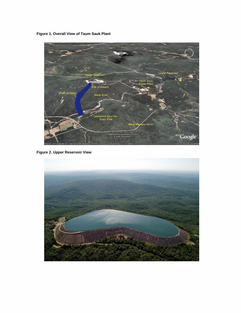
Figure 1. Overall View of Taum Sauk Plant
Figure 2. Upper Reservoir View

The Taum Sauk Plant is a peaking and emergency reserve facility. A typical daily summer cycle is to generate in the mid-morning by releasing water from the Upper Reservoir through the turbines to the Lower Reservoir, pump from the Lower Reservoir to the Upper Reservoir in the afternoon, generate in the evening and pump from the Lower Reservoir to the Upper Reservoir in the early morning. In the fall, winter and spring, the plant typically generates once per day. The normal maximum level for the Upper Reservoir was El. 1596 feet. Typically, the Upper Reservoir was drawn down less than 30 feet. A 30 foot drawdown represents 6 hours of single unit generation or 3 hours of double unit generation. The Upper Reservoir could be drawn down to El. 1525 feet without vortex problems at the morning glory outlet and possibly to El. 1515 feet if only one turbine/generator unit is operating. The Project operates under the direction of the load dispatcher in St. Louis. Both units could be put on full load in a few minutes.
2 December 14th, 2005 – The Incident At 5:00 AM, on this date, the northwest corner of the Dike around the Upper Reservoir breached over a width of about 700 feet, causing an uncontrolled, rapid release of water down the west slope of Profitt Mountain and into the East Fork of the Black River. An overall aerial view of the flow path is shown on Figure 3. As shown on Figure 4, the release flooded Route N while truck traffic was underway, and produced significant property and environmental damage to the Johnson’s Shut-Ins Campground. Figure 3. Overall View of the Breached Dike

Figure 4. View of Flow Channel at Route N
3 Root Cause Analysis A root cause analysis was conducted by RIZZO to identify the failure mechanism and develop design parameters for a possible entire rebuild of the Upper Reservoir, as an alternative to remediating the remnant Dike. The root cause investigation consisted of the following two phases: Phase I - Data Collection: The information collected included conditions before, during, and after the failure occurrence; personnel involvement; and environmental factors.
Phase II - Assessment: This phase included the following tasks:
1. Identify the problem. 2. Determine the significance of the problem. 3. Identify the conditions and actions preceding and
surrounding the problem. 4. Identify why the conditions in the preceding step existed.
To conduct these tasks, RIZZO adopted the Barrier Analysis Methodology, which is a systematic process for identifying physical, administrative, and procedural barriers or controls that should have prevented the incident. A barrier is a physical component, an instrument, a management policy, an operations manual, etc., that prevents an event. Table 1 lists all barriers that existed at Taum Sauk prior to the failure, including their postulated failure modes. The Root Cause Analysis indicated that the failure of the Upper Reservoir of the Taum Sauk Plant involved the rapid release of a massive amount of water. The Barrier Analysis used by RIZZO confirmed that the Breach of the Rockfill Dike, the primary Barrier to the Event, is the root cause of the “rapid release of water from the Upper Reservoir”. The failure mechanism was a stability failure of the Dike in the northeast corner caused by a rapid rise in the phreatic surface and the
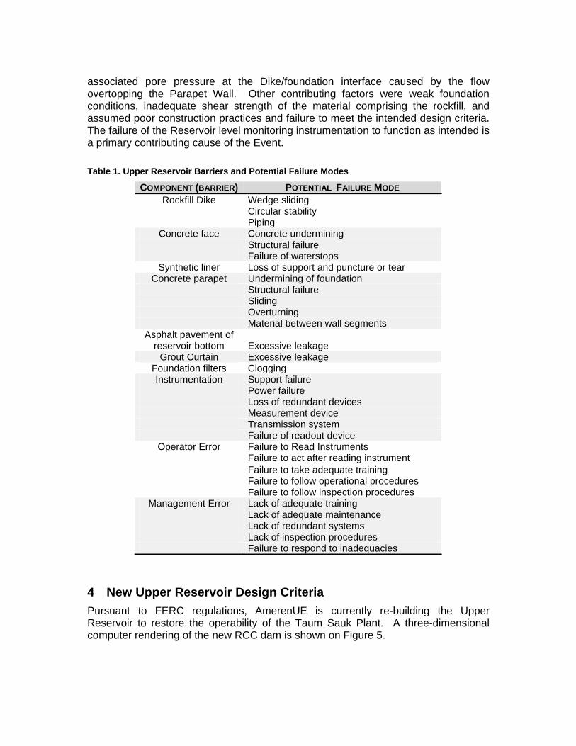
associated pore pressure at the Dike/foundation interface caused by the flow overtopping the Parapet Wall. Other contributing factors were weak foundation conditions, inadequate shear strength of the material comprising the rockfill, and assumed poor construction practices and failure to meet the intended design criteria. The failure of the Reservoir level monitoring instrumentation to function as intended is a primary contributing cause of the Event. Table 1. Upper Reservoir Barriers and Potential Failure Modes
COMPONENT (BARRIER) POTENTIAL FAILURE MODE Rockfill Dike Wedge sliding
Circular stability Piping
Concrete face Concrete undermining Structural failure Failure of waterstops
Synthetic liner Loss of support and puncture or tear Concrete parapet Undermining of foundation
Structural failure Sliding Overturning Material between wall segments
Asphalt pavement of reservoir bottom
Excessive leakage
Grout Curtain Excessive leakage Foundation filters Clogging Instrumentation Support failure
Power failure Loss of redundant devices Measurement device Transmission system Failure of readout device
Operator Error Failure to Read Instruments Failure to act after reading instrument Failure to take adequate training Failure to follow operational procedures Failure to follow inspection procedures
Management Error Lack of adequate training Lack of adequate maintenance Lack of redundant systems Lack of inspection procedures Failure to respond to inadequacies
4 New Upper Reservoir Design Criteria Pursuant to FERC regulations, AmerenUE is currently re-building the Upper Reservoir to restore the operability of the Taum Sauk Plant. A three-dimensional computer rendering of the new RCC dam is shown on Figure 5.

Figure 5. Computer Rendering of New RCC Dam Hydraulic Design Criteria The new RCC Dam will be constructed along the same alignment as the original Concrete faced Rockfill Dam constructed in the 1960s to impound the Upper Reservoir. Since the Upper Reservoir is founded on top of Taum Sauk Mountain, it has no watershed. The Probable Maximum Flood (PMF) for the new RCC Dam consists of the rainfall within the reservoir. Therefore, the Hydrology and Hydraulic Criteria are limited to two major factors, the elevation of the crest of the new RCC Dam, including freeboard, and the capacity of the proposed Overflow Release Structure (spillway). The overall design basis is to re-build the Upper Reservoir such that it will have the same electric generating capacity as the original Upper Reservoir with a normal pool and overall gross head as established in the FERC License for the Taum Sauk Plant. This leads to the following elevations for design:
Table 2. Design Elevations
LEVEL ELEVATION BASIS
Normal Operating Level 1597 Established in the FERC License
Crest of Dam 1601 4.0 feet of freeboard
Top of Parapet Wall 1604.5 Vehicle Guide Rail
Base of Dam Varies but generally in the range of EL 1500 and EL1460
Suitable rock foundation at or below foundation of original CFRD Dike
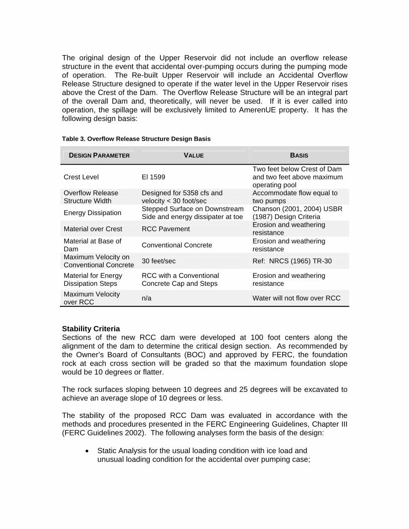
The original design of the Upper Reservoir did not include an overflow release structure in the event that accidental over-pumping occurs during the pumping mode of operation. The Re-built Upper Reservoir will include an Accidental Overflow Release Structure designed to operate if the water level in the Upper Reservoir rises above the Crest of the Dam. The Overflow Release Structure will be an integral part of the overall Dam and, theoretically, will never be used. If it is ever called into operation, the spillage will be exclusively limited to AmerenUE property. It has the following design basis: Table 3. Overflow Release Structure Design Basis
DESIGN PARAMETER VALUE BASIS
Crest Level El 1599 Two feet below Crest of Dam and two feet above maximum operating pool
Overflow Release Structure Width
Designed for 5358 cfs and velocity < 30 foot/sec
Accommodate flow equal to two pumps
Energy Dissipation Stepped Surface on Downstream Side and energy dissipater at toe
Chanson (2001, 2004) USBR (1987) Design Criteria
Material over Crest RCC Pavement Erosion and weathering resistance
Material at Base of Dam Conventional Concrete Erosion and weathering
resistance Maximum Velocity on Conventional Concrete 30 feet/sec Ref: NRCS (1965) TR-30
Material for Energy Dissipation Steps
RCC with a Conventional Concrete Cap and Steps
Erosion and weathering resistance
Maximum Velocity over RCC n/a Water will not flow over RCC
Stability Criteria Sections of the new RCC dam were developed at 100 foot centers along the alignment of the dam to determine the critical design section. As recommended by the Owner’s Board of Consultants (BOC) and approved by FERC, the foundation rock at each cross section will be graded so that the maximum foundation slope would be 10 degrees or flatter. The rock surfaces sloping between 10 degrees and 25 degrees will be excavated to achieve an average slope of 10 degrees or less. The stability of the proposed RCC Dam was evaluated in accordance with the methods and procedures presented in the FERC Engineering Guidelines, Chapter III (FERC Guidelines 2002). The following analyses form the basis of the design:
• Static Analysis for the usual loading condition with ice load and unusual loading condition for the accidental over pumping case;
• Seismic Analysis using Pseudo Dynamic Method developed by Chopra; and
• Finite Element Modeling and Analysis (FEM).
The RCC Dam is designed to meet criteria typically associated with a new Dam. The general design criteria and the overall design philosophy used to develop the rebuild design for Upper Reservoir are summarized as follows:
• RCC Dam is considered “wet” during Usual, Unusual, and Extreme loading conditions;
• RCC Dam is designed to achieve an acceptable post-seismic factor
of safety; • RCC Dam will be founded on slightly weathered to fresh rock; • Sliding stability is analyzed without cohesion; • Uplift pressure for stability analysis is calculated assuming that the
foundation drains will achieve a minimum drainage efficiency of 67 percent;
• Ice load of 5 kips at normal Operating Pool EL 1597; • The RCC/Rock Interface shear friction strength is assumed to be 45
degrees with zero cohesion for the yield acceleration calculation; and
• The shear strength of clay seams that might be encountered within
the foundation rock is assumed to be 25 degrees with zero cohesion (i.e., drained conditions).
Seismic Design Criteria This section presents the seismic design basis for the Upper Reservoir in terms of the rock outcrop ground motion spectra. The USGS provides seismic hazard assessments for the U.S. and areas around the world based on a comprehensive probabilistic analysis, for average return periods of 475 and 2475 years. Table 4 presents the spectral accelerations given by the USGS for Taum Sauk with Site Class B (shear wave velocity of approximately 2500 foot/sec). The shear wave velocity of the foundation rock at Taum Sauk corresponds to Site Class A, but no credit for this condition was taken in our analysis. A design spectrum was developed from this table. Additionally, a deterministic seismic hazard analysis was conducted considering the significant seismic sources for Taum Sauk presented in Table 5. The distance to the New Madrid and the Wabash Valley Seismic Source Areas represent the closest distance of the respective Seismic Sources to the Upper Reservoir. The analysis
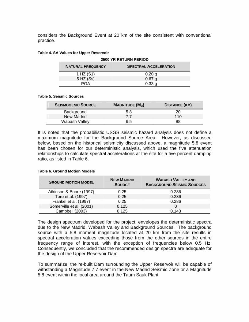
considers the Background Event at 20 km of the site consistent with conventional practice. Table 4. SA Values for Upper Reservoir
2500 YR RETURN PERIOD
NATURAL FREQUENCY SPECTRAL ACCELERATION
1 HZ (S1) 0.20 g 5 HZ (Ss) 0.67 g
PGA 0.33 g
Table 5. Seismic Sources
SEISMOGENIC SOURCE MAGNITUDE (MW) DISTANCE (KM) Background 5.8 20 New Madrid 7.7 110
Wabash Valley 6.5 88 It is noted that the probabilistic USGS seismic hazard analysis does not define a maximum magnitude for the Background Source Area. However, as discussed below, based on the historical seismicity discussed above, a magnitude 5.8 event has been chosen for our deterministic analysis, which used the five attenuation relationships to calculate spectral accelerations at the site for a five percent damping ratio, as listed in Table 6. Table 6. Ground Motion Models
GROUND MOTION MODEL NEW MADRID SOURCE
WABASH VALLEY AND BACKGROUND SEISMIC SOURCES
Atkinson & Boore (1997) 0.25 0.286 Toro et al. (1997) 0.25 0.286
Frankel et al. (1997) 0.25 0.286 Somerville et al. (2001) 0.125 0
Campbell (2003) 0.125 0.143 The design spectrum developed for the project, envelopes the deterministic spectra due to the New Madrid, Wabash Valley and Background Sources. The background source with a 5.8 moment magnitude located at 20 km from the site results in spectral acceleration values exceeding those from the other sources in the entire frequency range of interest, with the exception of frequencies below 0.5 Hz. Consequently, we concluded that the recommended design spectra are adequate for the design of the Upper Reservoir Dam. To summarize, the re-built Dam surrounding the Upper Reservoir will be capable of withstanding a Magnitude 7.7 event in the New Madrid Seismic Zone or a Magnitude 5.8 event within the local area around the Taum Sauk Plant.

5 Design Basis Foundation Shear Strength The subsurface information obtained during the original construction of the dam and additional borings drilled during the design of the new RCC dam indicated the prevalence of weak seams along low angle discontinuities with the foundation rock. At many locations, these weak seams consist of low plasticity clay. Therefore, we performed sliding stability analyses of the dam assuming the presence of the clay seams at various depths within the foundation rock. We also calculated the yield acceleration along these potential failure surfaces. The lowest factor of safety is postulated to occur when the clay seam is parallel to the Rock/Dam Interface at an angle of 10 degrees with the horizontal at a reasonable depth below the base of the Dam. For any other angle of the seams (either upward or downward), the factor of safety is higher than the factor of safety for clay seams parallel to the Rock/Dam Interface. The required friction angle with no cohesion was calculated for various depths to the clay seams. The results of these analyses indicate that a symmetrical RCC dam with 0.6H:1V upstream and downstream slopes constructed along a foundation sloping at 10 degrees or less will meet all FERC stability criteria even if a clay seam with a low friction angle is encountered within 20 feet of the base of the dam. A conventional RCC dam section would require RCC/Rock and rock shear strengths considerably higher than a clay seam. For this reason, the new RCC dam will consist of a symmetrical section similar in many ways to a hard fill dam. Foundation Preparation Requirements Due to the presence of clay seams within the foundation rock, additional foundation preparation requirements will be utilized during construction. These requirements consist of drilling holes within the foundation rock using air rotary drilling methods to a depth of 30 feet below the proposed foundation bottom. The locations of these holes are shown on Figure 6. Each hole is logged by a video camera to determine if continuous clay seams are present within the RCC foundation. A demonstration program conducted during the design phase of the dam indicated that a video camera can clearly identify clay seams within the foundation rock. Figure 6. Investigation Holes
If clay seams are encountered in all three holes, a three point analysis will be performed to estimate the dip of the continuous clay seam. The results of this investigation consisting of depth to clay seam, thickness of clay seam, dip of clay seam, and slope of the downstream rock, will be used to determine if the removal of the clay seam is necessary to meet stability criteria. RCC Mix Design Program The RCC mix for the proposed dam was developed considering the following factors:
• Re-use of the existing Rhyolite rockfill for the coarse and fine aggregate; • Use of non-commercial fly ash from AmerenUE facilities; • Relatively low required strengths due to the symmetrical cross section.
The development of the RCC mix began with performing a Phase I laboratory mix design program in the spring of 2006. This program consisted of 16 RCC mixes utilizing the existing rockfill as aggregate. This material was crushed to the proper gradation at a nearby rock quarry. Class F fly ash from a waste pond at AmerenUE’s Meramec facility was used in most of these mixes. The Phase I program also included Alkali Silica Reactivity (ASR) testing to determine if the Rhyolite aggregate is potentially expansive. The results of the Phase I program indicated that the non-commercial fly ash could be used to produce RCC, the Rhyolite was potentially expansive despite the presence of the Class F fly ash which mitigated some of the reactivity, and an RCC mix consisting of 200 pounds of cementitious content (cement and fly ash) and 3,600 pounds of aggregate will produce the required engineering properties (i.e., yield a compressive strength in excess of 1,500 psi after one year and a unit weight in excess of 146 pounds per cubic foot). The RCC Mix design program continued with a Phase II program consisting of the construction of an RCC test pad using the same materials with full scale construction equipment. The Phase II program was conducted in November 2006 and included saw cuts into the RCC test pad to determine the quality of the RCC. The results of this program indicated that the mix design recommended after the Phase I program was appropriate for the construction of the RCC dam. Seismic Analysis The RCC Dam will be constructed as monoliths connected by vertical planar joints, spaced about 90 feet horizontally. Each block will have a seismic response practically independent of the rest of the reservoir. A simplified 3-D analysis of the entire reservoir confirms that the 3-D analyses with lower frequencies correspond to segments of the reservoir vibrating in their “local” fundamental mode while the rest of the reservoir exhibits very small motions. Thus, the static and seismic analyses were conducted for a planar section representing the most critical segments of the reservoir using plane strain elements. The finite element mesh is depicted in Figure 7 for the critical section dimensions. The largest element dimension is about 7 feet.

Figure 7. Two-Dimensional First Mode of the Critical Section
The stiffness of the bedrock was represented by linear and rotational Soil-Structure Interaction (SSI) springs at the reservoir base. Best Estimate, Lower Bound and Upper Bound were estimated using the formulas by Gazetas (1990). The SSI springs were modeled by 35 sets of horizontal springs, vertical springs, and rotational spring-elements uniformly spaced at the reservoir-rock interface. In agreement with the SSI calculations, three finite element models were developed differing in the uniformly distributed spring to represent, respectively, the Best Estimate, Lower Bound and Upper Bound SSI conditions. A damping ratio of 5 percent of critical is considered for the reservoir material. When combined with the effects of soil structure interaction damping, a total damping ratio of 10 percent of critical was obtained, and was applied to all the vibration modes in all seismic analyses. A static analysis was conducted for self-weight of the reservoir. Water static forces were included in the analysis in accordance to the water pressures. All seismic loading cases consider the ground motion in the horizontal direction. Modal spectral analyses were conducted with the seismic input stipulated by the design spectrum. Altogether, the first 15 modes were included in the finite element analyses. The first three horizontal modes contain more than 95% of the mass participation, as presented in Table 7. The maximum stresses under seismic load are only 132 psi (both tension and compression). After adding the effects of dead weight and water pressures, the stress becomes all compression with a maximum of 192 psi, well below the capacity of the rolled compacted concrete. Table 7. Natural Periods and Horizontal Participation Factors
Mode Period (seconds) Mass participation (%) 1 0.168 69.6 2 0.095 0.10 3 0.084 22.7 4 0.045 1.9

Instrumentation Design The instrumentation for the new RCC dam will consist of both a Level Control System and a Level Protection System. The design of both systems is in general accordance with the Pumped Storage Technical Guidance document currently being drafted by an industry group working with the Pumped Storage User’s Group. In addition, the design is consistent with the Environmental Analysis issued to FERC by AmerenUE and the FERC’s forensic analysis of the Upper Reservoir breach. Considerable regulatory review from both state and federal agencies is incorporated into the design. The Level Control System will be used for normal plant operation and the Level Protection System will be a fail-safe backup system to the Level Control System. Multiple types of instrumentation equipment will be used for both systems. Redundancy will also be incorporated to mitigate the consequences of equipment failure. The Level Protection System will consist of two electrical sensing device type switches, which will be set a foot higher than the normal shutdown level of the pump cycle. If either switch is activated, a hard wired shutdown of the pump cycle will occur. Two mechanical float type switches will be included to back up the electrical switches. These mechanical switches will be set a half foot higher than the electrical switches. Two additional electrical switches will be located at the Overflow Release Structure (ORS). The elevation of the ORS is a foot higher than the electrical switches and a half foot higher than the mechanical switches. Actuation of either switch in the ORS will trip the pump cycle and provide an alarm. Cameras will be installed to allow plant operators to visually monitor the water level in the upper reservoir 24 hours per day. Redundant cameras will monitor a fixed staff gauge in a stilling well located in an Instrumentation Building cantilevered over the water. Additional cameras will provide a view of the reservoir.
6 Summary A new upper reservoir is currently under construction using rolled compacted concrete to construct the dam. The design of the dam included the evaluation of several design issues resulting from the foundation conditions, site characteristics and available materials. These issues resulted in a symmetrical dam section with relatively low strength RCC. These issues have been presented in this paper.

Authors Paul C. Rizzo is the President of Paul C. Rizzo Associates, Inc. an Engineering and Consulting firm. John P. Osterle is a Project Manager for Paul C. Rizzo Associates, Inc. in the Monroeville, Pennsylvania office. Thomas Hollenkamp is the Dam Safety Engineer for AmerenUE, the Project Owner, in their St. Louis, Missouri office. Craig Geismann is a Managing Supervisor of Hydro Engineering for AmerenUE, the Project owner. Please include also a short CV of the authors at this section. Dr. Rizzo began his professional career at D’Appolinia Consulting Engineers. There he rose from Project Engineer to President over an 18 year period. In 1984, Dr. Rizzo formed a new consulting firm that bears his name. In its 24-year history, RIZZO has grown to become an international firm specializing in dam design and remediation, water resources, geotechnical, power generation, and seismic projects. Today, the company employs about 200 people located in offices in Monroeville, PA; Columbia, SC; New York Region; St. Louis, Missouri, Oakland, California, Buenos Aires and Mendoza, Argentina; St. Petersburg, Russia; and Plzen, Czech Republic. The firm has been ranked as one of the “Top 100” firms by The P i t t s b u r g h B u s i n e s s T i m e s f o r t h e p a s t t h r e e y e a r s .
• During his 40+ year career, Dr. Rizzo’s achievements are evident across a broad range of civil engineering disciplines. • Dr. Rizzo’s broad experience includes his role as the Chairman of the Geotechnical Advisory Board for the new Second Avenue Subway Project in New York City - a $16 billion, decade-long project. This senior position among a very distinguished Board demonstrates his stature within the industry as a geotechnical expert. Additionally, this position demonstrates Dr. Rizzo’s ability to coalesce diplomatically with a panel of independent experts, a knowledgeable and experienced owner, and a large international engineering team.
• As a Seismic/Geotechnical Consultant to the Defense Nuclear Facilities Safety Board (DNFSB), Dr. Rizzo is involved in a review capacity at the Department of Energy’s nuclear facilities, including Hanford, Oak Ridge, Los Alamos, Pantex, and other sites. Dr. Rizzo has held this position for 18 continuous years, proving his technical competence and ability in regard to a wide range of seismic and geotechnical problems including seismically induced liquefaction, soil-structure interaction, and deformation analyses.

• Dr. Rizzo has led the analyses and design effort for the Saluda Dam Remediation project. State-of-the-Practice Dynamic Stability and Liquefaction Analyses (Seed and Harder Charts with finite element analyses) were completed for this semi-hydraulic fill embankment by or under the direction of Dr. Rizzo. He completed the required analyses and remediation design under the close scrutiny of an esteemed Board of Consultants, FERC Staff, and FERC Consultants. Technical issues were identified, discussed, and resolved. During this process, Dr. Rizzo’s respect and stature in the profession often led to quick resolution of many challenging issues surrounding this unique project. He is highly knowledgeable in the specialized areas of probabilistic seismic hazard analysis, dynamic soil properties, elastic & pseudo-non-linear deformational analysis (FLUSH, SASSI, SHAKE), permanent deformation analysis (Newmark, Hendron, FLAC) , dynamic pore pressure patterns for liquefiable and non-liquefiable soils, post-liquefaction strength degradation and strength recovery, effects of foundation fault movement on embankment performance, and the behavior of filters under seismic deformation and associated piping hazards. • Dr. Rizzo is a recognized expert in the field of safety evaluations and the seismic rehabilitation of dams. He has served on numerous panels, committees and consulting boards charged with the deliberation of seismic hazard evaluation, seismic design basis, soil-structure interaction, and other seismic issues related to geotechnical engineering for various types of projects. He is a Federal Energy Regulatory Commission (FERC) Part 12 Independent Consultant and has performed these inspections on dams throughout the United States. • Dr. Rizzo was recently named the 2005 recipient of the Metcalf Award presented by the Engineers’ Society of Western Pennsylvania (ESWP). Named for the ESWP’s first president, William Metcalf, this award is presented annually to an outstanding engineer whose lifetime achievements have extended the engineering community’s knowledge. This recognition from the oldest engineering society in the county is a result of a lifetime pursuit of professional excellence and proof positive of Dr. Rizzo’s competence and ability within his chosen field - namely as a Geotechnical and Seismic Expert and a leader within the engineering community.


![Time-varying jump tails - Duke Universitypublic.econ.duke.edu/~boller/Published_Papers/joe_14.pdf · varying± ± ± ± ± − (+ −]) ± (+ − ±, =,..., −] = −, −] = −,),](https://img.dokumen.tips/doc/110x75/5f9eb1e298e27c43de4b3c12/time-varying-jump-tails-duke-bollerpublishedpapersjoe14pdf-varying-.jpg)