Embed Size (px)
Citation preview
1 © Nokia 2017
The Evolution of R-PHYFrom Gen R-PHY to Gen FDX
SCTE Cable-Tec Expo: R-PHY Technical SessionDavid Eckard, CTO, Fixed NetworksOctober 17, 2017
Public

2 © Nokia 20172
What is next for DAA and R-PHY?R-PHY node trends result from two distinct areas of innovation
Let’s look at one innovation coming from each of these areas.
Virtualization
NFV
SDN
Virtualization
DAAWork flows
EPON
DPoE vCMTSService Chaining
vCCAP
• Virtual Network Functions• Work Flows• Service Chaining
Physical Node
• FDX• Silicon Advances• Flexibility
Public

3 © Nokia 2017
vCMTS on the R-PHY nodeVirtualization : Key Component of Node Evolution
Public
• Work flows automate deployment and configuration.
• Additional functionality easily added by adding new VNFs
• Operators demand vendor choice• vCMTS/service density challenges create
conversation around moving functions from headend to node (e.g., BPI+)
Remote-PHY+Onboard vCMTS
Service group
vCMTS
RPD
Remote-PHY
Service groupvCMTS
RPD
• Scale for power, size, space in the node and the cloud
• VNF-based vCMTS can be ANYWHERE, even on the R-PHY node itself
• Reduce the bandwidth requirements for aggregation (e.g. PON and cascaded Ethernet)
CCAP

4 © Nokia 2017
R-PHY Device in a Virtualized WorldIn the Node
RPD
Controller
OSP
Hub
Data
Cen
ter
Head
end
Routing
Switching
In the OSP
RPD
Controller
OSP
Hub
Data
Cen
ter
Head
end
Routing
Switching
In the Hub
RPD
Controller
OSP
Hub
Data
Cen
ter
Head
end
Routing
Switching
In the Headend
RPD
Controller
OSP
Hub
Data
Cen
ter
Head
end
Routing
Switching
In the Data Center
RPD
Controller
OSP
Hub
Data
Cen
ter
Head
end
Routing
Switching
Public

5 © Nokia 20175
What is next for DAA and R-PHY?R-PHY node trends result from two distinct areas of innovation
Virtualization
NFV
SDN
Virtualization
DAAWork flows
EPON
DPoE vCMTSService Chaining
vCCAP
• Virtual Network Functions• Work Flows• Service Chaining
Physical Node
• FDX• Silicon Advances• Flexibility
Public
6 © Nokia 2017
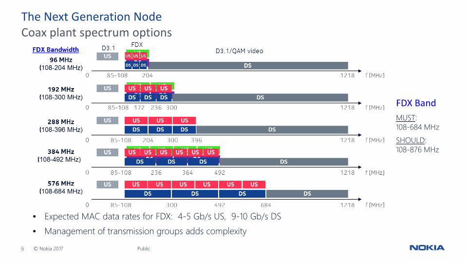
Coax plant spectrum optionsThe Next Generation Node
Public
• Expected MAC data rates for FDX: 4-5 Gb/s US, 9-10 Gb/s DS• Management of transmission groups adds complexity
FDX BandMUST:108-684 MHzSHOULD:108-876 MHz
7 © Nokia 2017
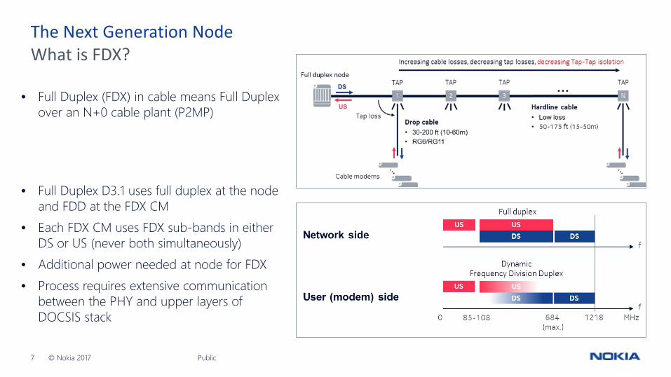
What is FDX?The Next Generation Node
Public
• Full Duplex D3.1 uses full duplex at the node and FDD at the FDX CM
• Each FDX CM uses FDX sub-bands in either DS or US (never both simultaneously)
• Additional power needed at node for FDX• Process requires extensive communication
between the PHY and upper layers of DOCSIS stack
• Full Duplex (FDX) in cable means Full Duplex over an N+0 cable plant (P2MP)
8 © Nokia 2017
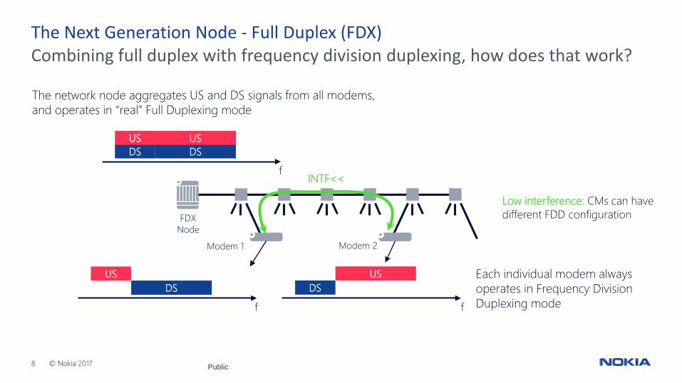
Combining full duplex with frequency division duplexing, how does that work?The Next Generation Node - Full Duplex (FDX)
The network node aggregates US and DS signals from all modems,and operates in “real” Full Duplexing mode
Each individual modem always operates in Frequency Division Duplexing mode
FDXNode
Modem 1 Modem 2
INTF<<
Low interference: CMs can have different FDD configuration
fDSUS
DSUS
f
USDS
fDS
US
Public
9 © Nokia 2017
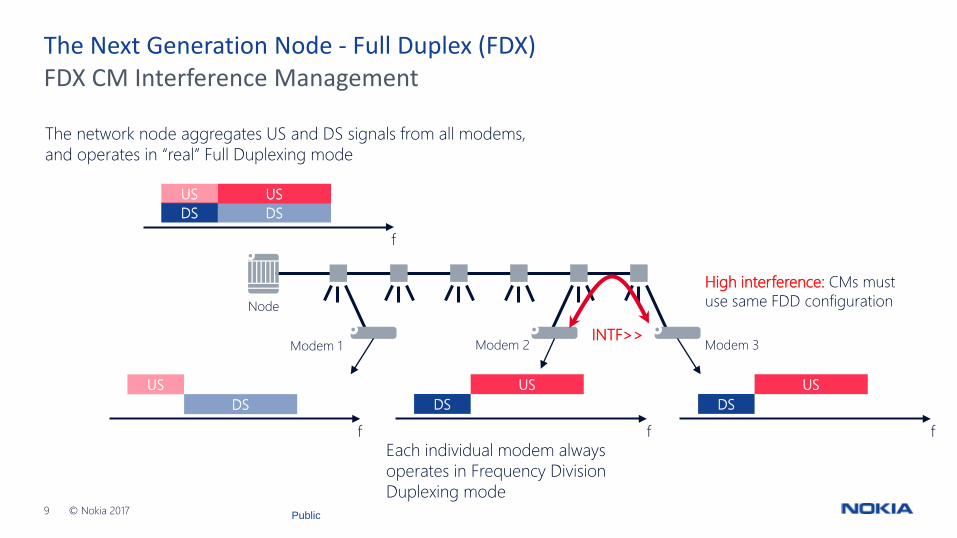
FDX CM Interference ManagementThe Next Generation Node - Full Duplex (FDX)
The network node aggregates US and DS signals from all modems,and operates in “real” Full Duplexing mode
Each individual modem always operates in Frequency Division Duplexing mode
Node
Modem 1 Modem 3Modem 2 INTF>>
High interference: CMs must use same FDD configuration
fDSUS
DSUS
f
USDS
fDS
US
fDS
US
Public

10 © Nokia 2017
Interference GroupsThe Next Generation Node - Full Duplex (FDX)
• Cable modems that heavily interfere are clustered in “interference groups”• All modems within one interference group have identical US and DS frequency bands• This avoids any US-to-DS full duplex interference for modems within the same interference group• Additional local functionality is needed in the scheduling process to take into account these interference groups.
fDSUS
DSUS
Node
INTF>>
f
USDS
fDS
US
INTF<<
Interference group 1 Interference group 2
Public

11 © Nokia 2017
10 GE
Fiber
FDX Design Considerations
Service group
Coax
Switch FDX R-PHY Node
Headend OSP
CCAP-core functionality
CPE
• Hardware upgrade (interface cards at a minimum) required for traditional CCAP.
• Software upgrade required for CCAP-core and vCMTS
• Requires N + 0 architecture• Requires new node (new RF and
electronics at a minimum)• FDX-Ready Nodes will likely be
deployed ahead of FDX CPE• Node must support FDX, all
versions of DOCSIS, and QAM video
• FDX CPE will likely follow FDX nodes by 12-18 months
• Network will have to support existing CPE
Public

12 © Nokia 2017
Virtualized Unified Architecture for Cable Access
With virtualization, MSOs can deploy the right technology for any situation.
Access Controller
Common controller Common routing and switching Any service, any medium
Edge Router
All-IP fiber R-PHY+Onboard vCMTSAccess node
vCMTS
PONAccess node
Public
R-PHYAccess node
vCMTSorCCAP-core
FDXAccess node
FDX vCMTS*

13 © Nokia 2017
The R-PHY DAA journey has only just begun.
• DAA extends useful life of HFC far beyond what was originally anticipated.• Virtualization eliminates difficult decisions and provides incredible flexibility.• Move complexity where is makes economical and operational sense.• Silicon advancements will greatly improve density and efficiency.• FDX opens dramatic capacity in the access network for new use cases.• A lot of exciting developments happening now. A lot more to come.
13 © Nokia 2017 Public

14 © Nokia 2017Public