Embed Size (px)
Citation preview

The EnviroMon System User Manual R5.06
General InformationChapter 1 Introduction - Essential reading for new usersChapter 2 Configuration planning - what to buy, what features to useChapter 3 Equipment - the modules that make up a systemChapter 4 Getting started - how to set up a starter kit
EnviroMon for Windows softwareChapter 5 Views - Displaying current and recorded dataChapter 6 Configuration dialogs - user input during configurationChapter 7 Normal dialogs - user input during normal operationChapter 8 How to... use all of those clever features
Software driversChapter 9 Drivers - for customers who want to write their own software
Technical informationChapter 10 Troubleshooting and maintenanceChapter 11 File formats - files used by EnviroMon for WindowsChapter 12 Communication protocols - driving the logger directlyChapter 13 Messages from the logger
Chapter 1: Introduction
IntroductionThe SystemThe EquipmentThe SoftwareOnline HelpContacting PicoLegal info

Introduction
This user manual contains nearly two hundred pages of online information, providing comprehensiveinformation about all aspects of the EnviroMon system.Please take a few minutes to read this introduction, as this will give you a brief overview of how thesystem works, and where to find additional information.
To continue reading the introduction, please press the button on the bar above each timeyou have finished reading a page.

The SystemThe EnviroMon system is designed for long-term recording of data from a number of locations.The system offers the following features:• permanent retention of recorded data on PC• wide range of data display and analysis options• easy-to-use software• telephone style connections for easy installation• modular system for easy upgrades• a wide range of options to report alarm conditions• support for remote data download (modem, GSM, IP, etc)
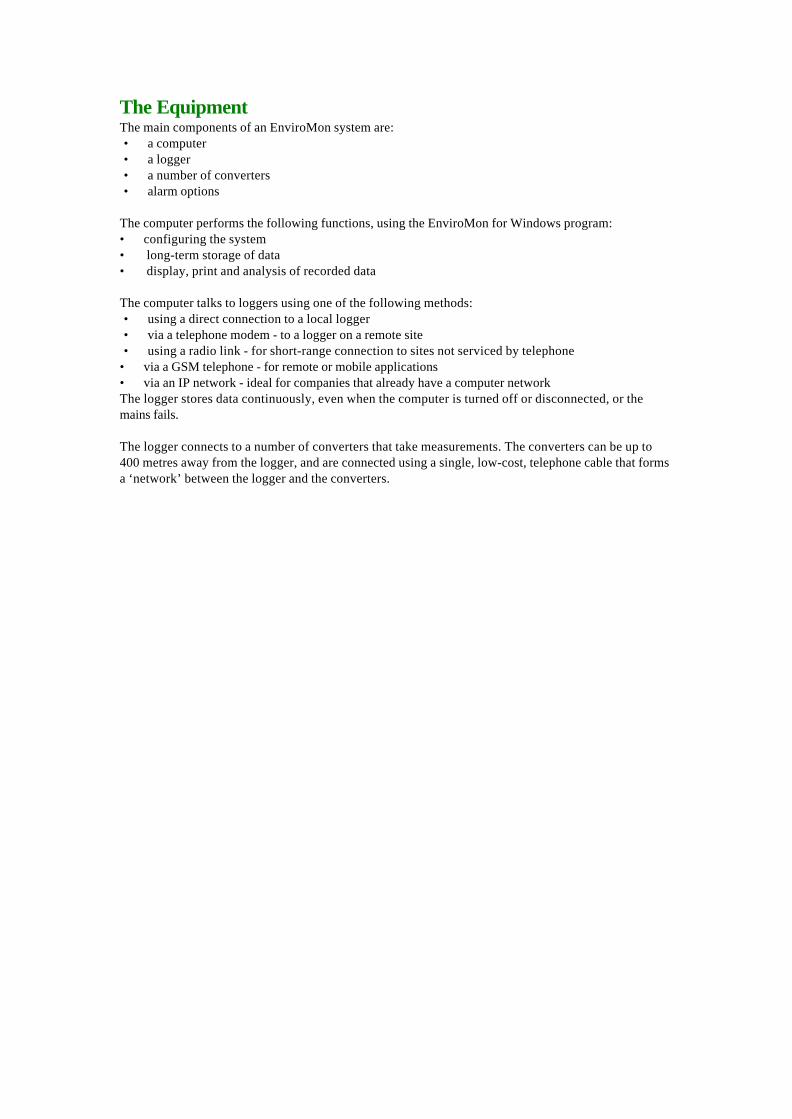
The EquipmentThe main components of an EnviroMon system are:• a computer• a logger• a number of converters• alarm options
The computer performs the following functions, using the EnviroMon for Windows program:• configuring the system• long-term storage of data• display, print and analysis of recorded data
The computer talks to loggers using one of the following methods:• using a direct connection to a local logger• via a telephone modem - to a logger on a remote site• using a radio link - for short-range connection to sites not serviced by telephone
• via a GSM telephone - for remote or mobile applications• via an IP network - ideal for companies that already have a computer networkThe logger stores data continuously, even when the computer is turned off or disconnected, or themains fails.
The logger connects to a number of converters that take measurements. The converters can be up to400 metres away from the logger, and are connected using a single, low-cost, telephone cable that formsa ‘network’ between the logger and the converters.

The Software
EnviroMon for Windows is used both to configure an EnviroMon system, and to extract and analysedata from the system.
To run EnviroMon for Windows under Windows 95:• Press the Start button• Select Programs• Select Pico Technology• Select EnviroMon for Windows
When you first start up the EnviroMon software, the system is not yet configured, so the computerdisplays the configuration panel.The top button on the configuration panel selects a guided tour: this will take you, step by step,through the process of setting up a simple system.The final stage of configuring a system is to press the Program button: this writes a configuration tothe logger.
When you start up the EnviroMon software after the system has been configured, the softwaretransfers the readings stored in the logger to a data file on your computer, and then displays theMonitor view which shows the current value of each measured parameter.From the monitor view, you can use the menu to get back to the configuration panel, or to any of thereporting views.

Online HelpEach dialog or view in EnviroMon for Windows has a link to the corresponding information in this helpfile.• to get help from a dialog, press the Help button
• to get help from a view, press the button
Once in this help file, you can find things in several ways:• press the Contents button for a full list of the items covered in this file• press Index and then specify a keyword that describes what you are looking for
• press the button to move on to the next topic• press an underlined area to link to a related topic

Legal info
LicensingBoth the demonstration and production versions of Enviromon for Windows may be copied and usedfreely on any number of computers.
LiabilityPico Technology Limited does not accept responsibility for any loss or injury caused by the use of PicoTechnology equipment or software. It is the user’s responsibility to ensure that the product is suitablefor the user’s application.
Trade marksWindows is a registered trademark of Microsoft Corporation.Pico Technology Limited and EnviroMon are internationally registered trade marks.

Chapter 2: Configuration
Configuration planning Who will be responsible for the system? What do you want to measure? What action is required on alarms? What should happen on power failure? Data storage and reporting Where should equipment be placed? How to validate the system Security

Configuration planning
EnviroMon is a very flexible system. It is made up of a number of separate modules: you simply choosethe modules that you need to do the job. In addition, there are several software options that can beconfigured so that the logger will do exactly what you want.
This section describes the points that you should consider when setting up an EnviroMon system.
• Who will be responsible for the system?• What do you want to measure?• What action is required on alarms?• What should happen on power failure?• Data storage and reporting• Where should equipment be placed?• How to validate the system• Security
Who will be responsible for the system?
For a small configuration, one person can easily install the system and operate it on a day-to-day basis.
Larger systems are often installed by external contractors, but it is essential to have someone within thecompany who will be responsible for maintaining thesystem once it is installed. This person should be involved at the earliest stages in the planning of thesystem, so that they understand how it works and can easily make small changes to the system asrequirements change.
What do you want to measure?
EnviroMon takes readings from a number of sensors distributed around a site. These sensors areconnected to converters that transform the analogue signals from the sensor into digital signals: thesedigital signals can then be transmitted reliably and accurately to the logger. The type of sensor andconverter depends on what you wish to measure.
Temperature
EnviroMon provides full support for three different temperature measuring techniques: it can also workwith other techniques if required.• Precision thermistors are relatively low cost and they are highly accurate (0.1°C) , but only over a
relatively limited temperature range, for example -40 to 30°C or 0 to 70°C. • Pt100 platinum resistance (PRT) sensors cover a wider temperature range- -200 to 650°C- and are
available in DIN standard (0.3°C), tenth-DIN (0.03°C) and even higher accuracies. • Type K thermocouples work over a range -270 to 1370°C: they are available in a wide variety of
probes from a large number of suppliers. There is a standard connector, so thermocouples fromdifferent suppliers are interchangeable. Typical accuracy is 0.5°C at ambient temperature, and errorincreases as the temperature goes away from ambient.
ThermistorsThe standard EL015 and EL039 EnviroMon temperature sensors are precision thermistors sealed in astainless steel cylinder. The sensor is fitted with a 5-metre cable and a connector which plugs straightinto an EL001 temperature converter. Each EL001 can accept three sensor inputs. The sensor cable canbe extended to a maximum of about 100 metres: this will introduce an error of less than 0.1C in thetemperature measurement.
At temperatures below 0C, the cable may become brittle, and must not be flexed. At temperatures over70C, the cable may become soft and easily damaged.
The EL015 and EL039 temperature sensors have an accuracy of 0.1C over 0 to 30C, and 0.2C over -20 to50C. Outside this range, we recommend the use of Pt100 or Type K sensors.
For localised temperature measurement- for example, measuring the temperature of a critical componentin a control system- Pico can also supply thermistor sensors as bare beads, approx 1mm diameter.
Type K thermocouplesThe CM004 Type K thermocouple conditioner supports the full temperature range for type K. It is fittedwith a standard miniature thermocouple connector.Pt100 platinum resistanceThe CM005 Pt100 conditioner covers the range -200 to 350C. It has four screw-terminal connectors, andcan be used with two, three or four-wire sensors.
HumidityEnviroMon can measure humidity using the EL031 temperature and humidity sensor and EL026converter. The converter contains calibration information for the sensor, so the units are supplied as apair. The EL031 contains both a temperature sensor and a humidity sensor. The humidity sensor has acalibrated accuracy of 2%.
LightThe EL031 light sensor is intended to provide a qualitative measure of light level. It connects to one ofthe channels of an EL001 converter. The sensor gives a log-scaled reading between 0 an 100%, where 0is complete darkness and 100 is full sunlight. For more accurate light measurement, see measurementmade easy.

Door open/closedThe EL029 door switch can be connected to one of the channels of an EL001 converter. The loggerreports whether the door is open or closed, and any statistics show the percentage of time the door wasopen during any period.
Other parameters
There are three general-purpose converters for use with the EnviroMon system.• EL016 8-channel voltage converter• EL036 2-channel signal conditioner converter• EL037 3-channel voltage/4-20mA converter
The EL016 has eight inputs that can measure signals between 0 and 2.5 volts. EnviroMon can beprogrammed to convert the voltages into some other units (for example, pressure) and display them inthose units.
The EL036 accepts two signal conditioner modules, for example the CM004 Pt100 conditioner describedabove. There is a wide range of signal conditioning modules that are tailored to work with specificsensors, and also general purpose conditioners to work with 4-20mA or 0-5V transmitters. SeeMeasurement made easy for more details of signal conditioners.
The EL037 has three inputs that can be configured to measure ±2.5Volts, ±10Volts and 4-20mA.EnviroMon can be programmed to convert the measurements into some other units (for example,pressure) and display them in those units.
Bear in mind when selecting sensors that EnviroMon is a low-power system, hence it can carry onrunning when mains fails. Where possible, select low-power sensors. If it is essential to use a sensorthat requires a lot of power (for example gas sensors), you should consider either providing a localpower supply for the EL036 that it is connected to, or using the El018 battery backup unit.
What action is required on alarms
EnviroMon can be configured to sound an alarm if a temperature goes out of range (high or low) or if asensor fails.
For many applications, it is not necessary to have alarms for all sensors, so the alarm function for anysensor can be disabled. It is also possible to enable the alarm only during certain time ranges, forexample during working hours (eg 9 to 5, Monday to Friday).
It may be desirable to have an alarm on sensor failure, but not on temperature out of range. This can bedone by leaving the alarm enabled and setting a wide temperature range.
If the temperature normally goes out of range for short periods, it is possible to hold off (delay) alarmsfor a specified period. For example, if a freezer periodically goes through a defrost cycle lasting 15minutes, an alarm holdoff of 20 minutes would prevent the defrost cycle from causing alarms.
The high and low threshold, disable and holdoff can be set individually for each sensor.
The logger contains a built-in audible alarm: if the area where the logger is mounted is continuouslymanned, the built-in alarm is sufficient.
If the logger area is not continuously manned, it may be necessary to use a remote audible alarm, eitherin the workarea or in a security control room. This can be linked to the logger using the network cable.
If it is necessary to respond to alarms when the site is unmanned, the alarm dialer module can maketelephone calls to several numbers and deliver a voice message.

What should happen on power failure
For some applications, it is not necessary to collect or store data if mains power fails.
If continuous operation during mains failure is required, there are two options:
• fit 4xAA batteries into the logger. This provides several hour’s backup, but the batteries must bechanged from time to time
• install an EL018 dialer/battery backup module: this contains a lead-acid battery that will give 24hours’ operation in the event of mains failure. It is continuously kept charged while mains power ispresent.
Data storage and Reporting
Data storage and reporting requirements vary enormously, depending on the application. There arethree main options:• monitor temperatures - use the logger only for immediate temperature monitoring and alarms• print out reports at regular intervals, directly from the logger• store the data on computer
The logger can be connected to either a tally roll printer or to an Epson A4-paper printer. It can print thecurrent temperatures, and can also print out a periodic summary which shows the minimum, maximumand average readings, together with the number of alarms and the total alarm duration. This approach isuseful if there is not space for a computer, or if staff are not familiar with computers. These reports canbe printed out either at regular intervals, or on request.
If a computer is used, data is transferred to the computer automatically each time the user runs theEnviroMon program on the computer. Storing data on the computer has a number of advantages:• data can easily be backed up for added security• if the computer already has access to a printer, it is not necessary to buy a separate printer for the
logger• the computer software offers a wider range of report formats• it is possible to transfer data to other applications for further analysis• the computer need not be on the same site as the logger (see remote data access)
Once data is stored on the computer, it can be processed in a number of ways:• a spreadsheet-style display, which can be transferred to a spreadsheet for further analysis• a graph of readings against time, over periods from hours to years• a period summary which shows the minimum, maximum and average reading for each sensor during
the period, together with the number of alarm events and the total alarm duration.• a list of alarm events: it is possible to add notes about action taken on alarm.
It is possible to specify a backup path for files: this can either be a diskette or a network drive. If youspecify a diskette, the backup should be done manually, using the backup option on the file menu. Ifyou specify a network drive, you can also request an automatic backup each time you exit from theprogram.
It is also possible to specify that old files should be deleted after a period of time: the options are• never• delete after a month• delete after a quarter• delete after a year
If you are collecting data every minute, this will require about 1.6Megabytes per year. Most computershave at least 1000 Megabytes of disk space, so it is not usually necessary to delete old data.

Remote data collection
It is possible to access logger data remotely using either a radio modem or a telephone modem.
Radio modemOne computer can maintain radio modem links to several remote loggers. Because EnviroMon requiresvery little power, the remote loggers can easily operate using a battery that is kept charged using a solarpanel. The logger has built-in power saving features to turn off the radio modem when it is not required.
Telephone modemThe EnviroMon software running on a PC can use a modem to make a telephone call to a remote logger,then extract data from the logger and terminate the connection.
The logger can be configured to permit the modem to answer telephone calls only during a narrow timerange. This means, for example, that the logger data can be downloaded at night using a telephone linethat is allocated for other uses during the day.
Where should equipment be placed?
Each EnviroMon converter turns sensor inputs into digital signals: these digital signals can betransmitted quite long distances through the network cable. Converters should be a maximum of 400metres from the logger.
The logger can therefore be placed wherever information is required, for example in an office area, andthe converters can be placed near where parameters are to be measured.
Thermistor sensors are supplied with a 5-metre cable that can be extended up to 100 metres.
Alarm relay and dialer modules are best placed close to the logger, to minimise the risk that a break inthe network could prevent the logger from operating the relay or dialer.
Security
It is not possible to change the logger configuration from the logger keypad: it is necessary to use acomputer.
The EnviroMon for Windows software normally allows full access to both the data display andconfiguration functions. If, however, you enter details of users, you can specify which users are allowedto access the configuration menu.
How to validate the system
It will be necessary to check that all parts of the system work- this is essential once the system isinstalled, and should be repeated at least yearly thereafter.
We recommend that you create a checklist of features to test, while you are deciding what theconfiguration will be, then you can use this checklist once the system is installed. See the sections onMaintenance and Calibration for some ideas on testing.
If possible, you should operate the system for a period of time to ensure that it is working correctly,before you start to rely on the results.
When deciding on tests, the test is as lifelike and as complete as possible. For example, if you are usinga dialer, you should simulate a fault, then verify that the logger activates that dialer, the dialer calls thecorrect telephone numbers, and the persons called understand how to acknowledge the call.

Chapter 3: Equipment
GeneralConnectorsNetworkScrew terminal network connections
SensorsThermistor temperature sensorsLight sensorDoor switch
ConvertersEL001 Triple temperature converterEL017 IP65 temperature converterPP046 Temperature/humidity converterEL016 Voltage converterEL036 Signal conditioner converterEL037 Voltage/ 4-20mA converter
LoggerEL008 Logger with displayEL005 Logger without display
Alarm devicesEL006 Remote alarmEL018 Dialer adapter/battery backupEL011 Alarm relay
Connectors
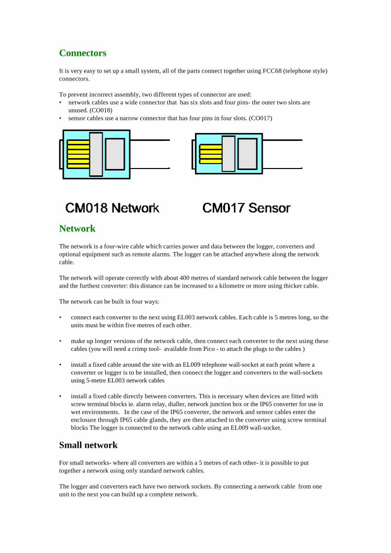
It is very easy to set up a small system, all of the parts connect together using FCC68 (telephone style)connectors.
To prevent incorrect assembly, two different types of connector are used:• network cables use a wide connector that has six slots and four pins- the outer two slots are
unused. (CO018)• sensor cables use a narrow connector that has four pins in four slots. (CO017)
Network
The network is a four-wire cable which carries power and data between the logger, converters andoptional equipment such as remote alarms. The logger can be attached anywhere along the networkcable.
The network will operate correctly with about 400 metres of standard network cable between the loggerand the furthest converter: this distance can be increased to a kilometre or more using thicker cable.
The network can be built in four ways:
• connect each converter to the next using EL003 network cables. Each cable is 5 metres long, so theunits must be within five metres of each other.
• make up longer versions of the network cable, then connect each converter to the next using thesecables (you will need a crimp tool- available from Pico - to attach the plugs to the cables )
• install a fixed cable around the site with an EL009 telephone wall-socket at each point where aconverter or logger is to be installed, then connect the logger and converters to the wall-socketsusing 5-metre EL003 network cables
• install a fixed cable directly between converters. This is necessary when devices are fitted withscrew terminal blocks ie. alarm relay, dialler, network junction box or the IP65 converter for use inwet environments. In the case of the IP65 converter, the network and sensor cables enter theenclosure through IP65 cable glands, they are then attached to the converter using screw terminalblocks The logger is connected to the network cable using an EL009 wall-socket.
Small network
For small networks- where all converters are within a 5 metres of each other- it is possible to puttogether a network using only standard network cables.
The logger and converters each have two network sockets. By connecting a network cable from oneunit to the next you can build up a complete network.
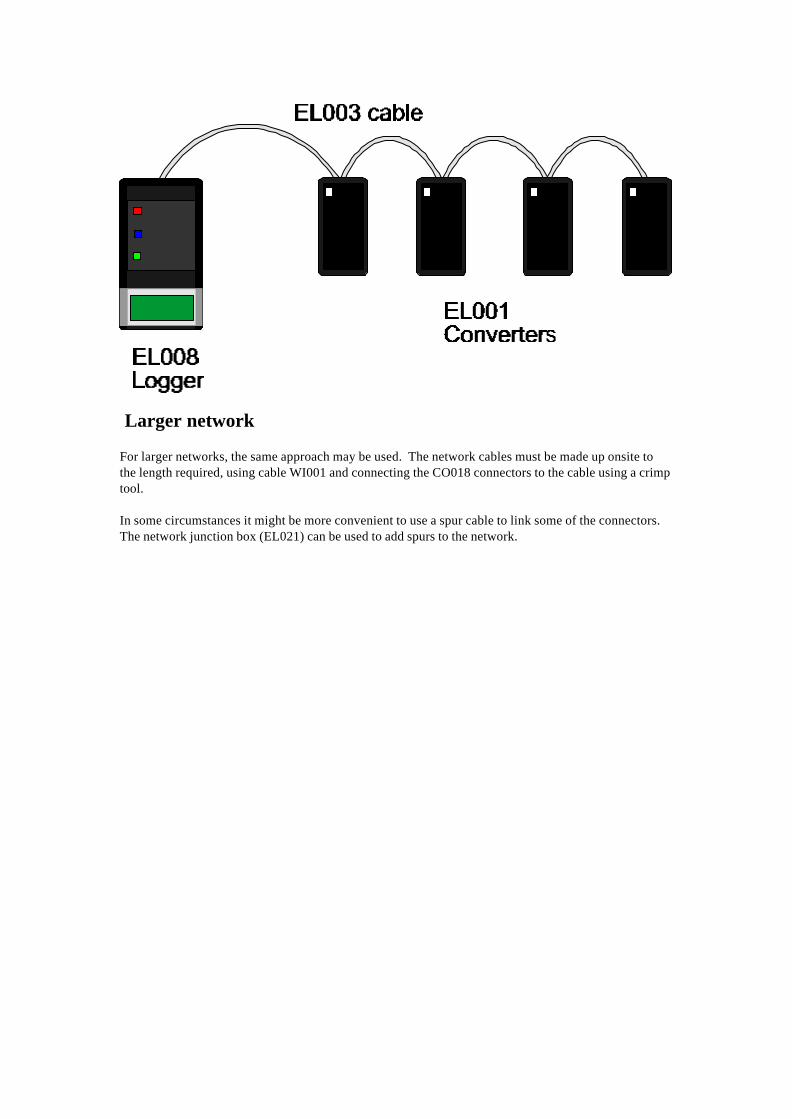
Larger network
For larger networks, the same approach may be used. The network cables must be made up onsite tothe length required, using cable WI001 and connecting the CO018 connectors to the cable using a crimptool.
In some circumstances it might be more convenient to use a spur cable to link some of the connectors.The network junction box (EL021) can be used to add spurs to the network.

Fixed network
For the largest networks, ie a large number of converters or converters which are widely spaced, themost satisfactory installation is a fixed network. Place an EL009 wall-socket or EL021 network junctionbox at each location where a converter or logger is required and use a standard 5-metre cable to connectthe socket to the logger or converter.


Screw terminal connections
The following EnviroMon devices are fitted with screw terminal blocks:
EL011 Alarm Relay EL017 IP65 Converter EL018 Dialer/Battery Backup Unit EL021 Network Junction Box
The screw terminal block connects the device to the network instead of using the telephone sockets.The following diagram shows the connections linking the device to an EL009 wall socket:
You should connect adjacent units using four core cable, eg Pico WI003. Connect terminal 1 to terminal1, terminal 2 to terminal 2, et cetera. The following table shows the signals associated with eachconnection:
Connection Signal1 Data A2 Data B3 Power (12-18V)4 Ground

Temperature Sensors
A sensor is required at each location where you wish to measure temperatures.
EL015/EL029 Temperature Sensors
The sensor is a steel tube about 5cm long. It has a 5-metre cable and there is a sensor connector at theother end of the cable. The sensor should be located where you wish to measure the temperature, eg ina refrigerator, tank or room. The connector fits into one of the three sensor sockets on a converter.
The sensors can be attached either directly to the converter, or using an extension cable up to 100metres long. The sensor adapter EL020 provides an easy way of extending sensor cables. The standardsensor extension cable (EL032) is 5 metres long.
Standard sensor cables are not flexible at low temperatures: if it is necessary to move the cables, theyshould be warmed up before flexing.

EL031 Light Sensor
The EL031 Light Sensor connects to a standard temperature converter (EL001) using the suppliedsensor extension cable.
The EL031 is intended to give a qualitative measure of light intensity. It has a logarithmic response, so itis useful at a wide range of light levels. It responds both to visible and to infra-red light.
When the logger is configured for use with a light sensor, the display on the logger reports a valuebetween 0 and 100%. 0% means complete darkness: 100% means full sunlight. Repeatability betweenunits is ±5%. If you require accurate (rather than qualitative) measurements or a specified range ofwavelengths, and can identify a suitable voltage-output sensor, you can use it with the EL016 or EL036converters.
The EL031 is designed to work with logger version 13 and above. If, when you power on the logger, itreports a logger version of 12, please contact Pico Technology Ltd.
The light sensor module can be attached to a wall using either adhesive foam or by removing the coverand using two screws to attach the unit to the wall.

EL029 Door Switch
The EL029 door switch connects to a standard temperature converter (EL001) using the supplied sensorextension cable. When the logger is configured for use with a door switch, the display on the loggerreports either 'Open' or 'Closed'.
Graphs and summary reports show the percentage of each sampling period that the door is open: 0%means permanently closed, and 100% means permanently open.
The EL029 is designed to work with logger version 13 and above. If, when you power on the logger, itreports a logger version 12, please contact Pico Technology.
The door switch module contains a built-in reed switch which can be activated using a magnet attachedto the door. Alternatively, if it is not practical to mount the door switch for operation with a magnet, anexternal micro-switch can be wired to the screw terminals inside the door switch module.
The door switch module can be attached to the wall using either adhesive foam, or by removing thecover and using two screws to attach the unit to the wall.
The black bar labelled b is the ideal location to place a magnet to activate the internal reed switch.
To attach an external microswitch make a hole in the case, insert the cable through the hole and strapthe cable round the central pillar. Attach the wires to connectors marked a.
For additional security, use a Tyrap to attach the cable to the two holes marked c on the left of theconnector block.

Sensor connections
If you need to connect standard sensors directly to an IP65 converter, or flexible cable sensors tostandard converters proceed as follows:
To connect the standard sensor to the IP65converter:• hold the cable vertically with the plug upwards with the clip side toward you• cut off the sensor connector• remove the two right-hand side wires• use the two left hand side wires (normally red and blue)
To connect flexible cable sensors to standard converters you will need to attach a sensor connector to alength of 4 core flat cable then connect the two wires from the sensor to the left hand two wires on thelength of 4 core cable.


EL020 sensor adapter
The EL020 sensor adaptor has two sensor sockets, back to back. If it is necessary to extend a sensorcable, it is easy to do this by making up a cable of the required length with plugs at each end, then usingthe EL020 to attach one end of this cable to the sensor cable.

Converters
The converter is the means by which the sensor signal is converted to a number which is then sent tothe logger.
Each converter has an address, which identifies it to the logger. Most converters are supplied with theaddress set to 1: The Change converter Address program can be used to change the address.
You can have up to 10 converters for each system using a mix of standard, IP65, humidity or voltageconverters.

EL001 Temperature converter
The standard converter is a small black box. There are three narrow sockets at one end: these are forsensors. At the other end, there are two wide sockets for the network, and a red light (LED).
The red light flashes continuously immediately after the system is turned on. Once the system isrunning normally, the light goes out and, thereafter, flashes briefly each time the converter takes areading.
Each converter has an 'address'- a number between 1 and 15 - written on the top right hand corner. Eachconverter on the network must have a different address which relates to its position on the networkThe converter will already be programmed with an address but you can change this through theinstallation software. The three sockets are marked with channel numbers.
When you install the system, the logging software will ask you for the address number and where eachof the three sensors are which relate to that converter address. For large networks, it is best to make aplan of the layout before starting installation.
Standard converters are not waterproof: if you wish to place converters in an environment where theywill be exposed to moisture, you should use an IP65 converter.
EL017 IP65 Temperature converter
The IP65 converter is identical to the standard converter, but is housed in an IP65 case: the IP rating is ameasure of its resistance to water and dust.
The case is fitted with five cable glands: the cable glands are for two network cables (in and out) andthree sensor cables. The unit is supplied with stoppers in each cable gland: the stoppers can be left inplace to seal unused cable glands.
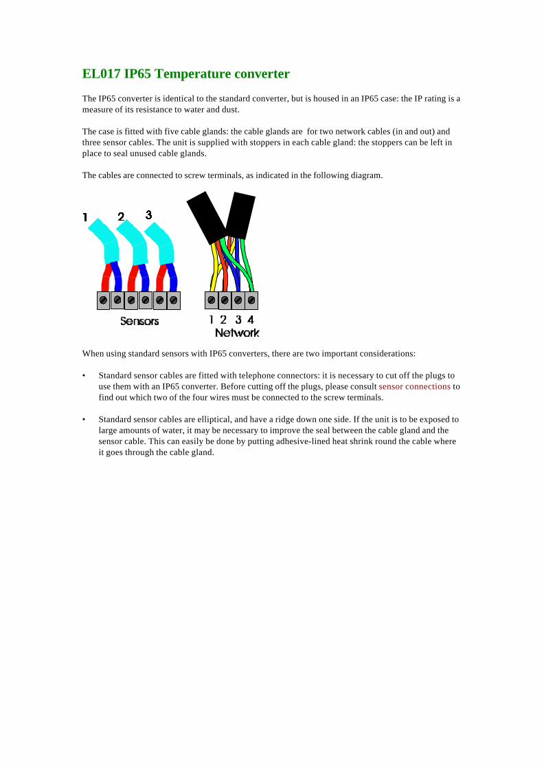
The cables are connected to screw terminals, as indicated in the following diagram.
When using standard sensors with IP65 converters, there are two important considerations:
• Standard sensor cables are fitted with telephone connectors: it is necessary to cut off the plugs touse them with an IP65 converter. Before cutting off the plugs, please consult sensor connections tofind out which two of the four wires must be connected to the screw terminals.
• Standard sensor cables are elliptical, and have a ridge down one side. If the unit is to be exposed tolarge amounts of water, it may be necessary to improve the seal between the cable gland and thesensor cable. This can easily be done by putting adhesive-lined heat shrink round the cable whereit goes through the cable gland.

EL026 Temperature/Humidity Converter
Specification
Temperature Range -40 to 85°CAccuracy ±0.2°C (0 to 70°C)
±0.3°C (rest of range)Humidity Range 0 to 100%
Accuracy ±2% (0 to 90%)
The EL026 converter contains calibration information specific to the EL030 humidity sensor. Pleaseensure that the sensor is used only with the converter that it was supplied with. Each unit in the pairhas a label on the base which shows the serial number of the sensor.
Each EL001 or EL026 converter has an address - a number between 1 and 15. If you wish to connectmore than one converter to your logger, each converter must have a different address. If you have twoconverters with the same address, install the software on your computer and then use the 'Changeconverter address'program to change the address of one of the converters.
The EL026 is designed to work with logger version 13 and above. If, when you power on the logger, itreports a logger version of 12, please contact Pico Technology.
The sensor must be situated away from direct contact with water and away from sunlight. Temporaryexposure to either is unlikely to damage the unit, but the unit will give incorrect readings while it remainsexposed.
The sensor can be attached to the wall either using adhesive foam, or by removing the cover and usingtwo screws to attach the unit to the wall.

EL016 Voltage converter
The EL016 voltage converter accepts eight voltage inputs. Each input can accept a voltage in the range0 to 2.5 volts.
The EnviroMon network allows a maximum of 3 values per converter, so the EL016 appears on thenetwork as three separate addresses. The following table shows the pin connections and channelnumbers for an EL016: Address A is the first address, B is the second address etc. An EL016 with astarting address of 4 would appear on the network as addresses A=4, B=5 and C=6.
Address Channel PinA 1 5A 2 9A 3 4B 1 8B 2 3B 3 7C 1 2C 2 6Ground 1
The EL016 is designed to work with logger version 15 and above. If, when you power on the logger, itreports a lower logger version, please contact Pico Technology.
It is possible to display the voltages as other parameters - see the PSC file section of the signalconditioner help file for more information.

EL036 Signal conditioner converter
The EL036 signal conditioner accepts two signal conditioners. Alternatively, it can be used for twovoltage inputs in the range ±2.5 volts.
The following signal conditioners may be used:ConditionerCM004 Pt100 platinum resistance TemperatureCM005 Type K Thermocouple TemperatureCM007 4-20mA (powered) VariousCM008 4-20mA (isolated) VariousCM015 10V bridge Pressure, LoadCM019 Current transformer AC current, power
The EL036 is fitted with a DC power connector. As long as the current used by all signal conditionerson the network is less than about 50mA, it is not necessary to attach a power supply. It will usually onlybe necessary to attach a power supply with CM007 conditioners (max 20mA per conditioner) and withCM015 if the bridge resistance is less than about 500 ohms.
The EL036 is designed to work with logger version 15 and above. If, when you power on the logger, itreports a lower logger version, please contact Pico Technology.
Click here for more information about signal conditioner modules.

EL037 Voltage/ 4-20mA converter
The EL037 has four inputs, however only three can be used with logger version 15 and earlier. It alsohas an external power input: this can be used to supply power (perhaps 12 or 24V, depending onrequirements) to the sensors.
Each input can be configured using jumpers to accept either ±2.5V,±10V or 4-20mA. It can be configuredfor other voltage ranges and for resistance measurement with minor component changes. The followingdiagram shows how to set a jumper to select the input type for a channel.
When measuring voltages, or for measuring 4-20mA with the transmitter supplying the loop current, theinput is connected between In and GND. The PWR connector can be used to supply power to thetransmitter:
When measuring 4-20mA with the EL037 supplying loop current, the transmitter should be connectedlike this:


EL008 Logger with Display
The logger can be used with a computer or as a stand-alone logger. If you use a stand-alone logger, youwill still need to connect it to a computer during the installation and set up process. However, once thesystem is operational, you can disconnect the computer and control the logger using the built inbuttons and display.

Connections
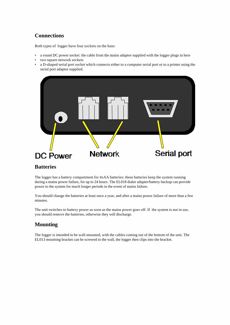
Both types of logger have four sockets on the base:
• a round DC power socket: the cable from the mains adaptor supplied with the logger plugs in here• two square network sockets• a D-shaped serial port socket which connects either to a computer serial port or to a printer using the
serial port adaptor supplied.
Batteries
The logger has a battery compartment for 4xAA batteries: these batteries keep the system runningduring a mains power failure, for up to 24 hours. The EL018 dialer adapter/battery backup can providepower to the system for much longer periods in the event of mains failure.
You should change the batteries at least once a year, and after a mains power failure of more than a fewminutes.
The unit switches to battery power as soon as the mains power goes off. If the system is not in use,you should remove the batteries, otherwise they will discharge.
Mounting
The logger is intended to be wall-mounted, with the cables coming out of the bottom of the unit. TheEL013 mounting bracket can be screwed to the wall, the logger then clips into the bracket.


Logger Display
The logger with display is a large, black box with an LCD display and three buttons - red, blue andgreen. Under normal operation these buttons have the following functions:
• red - Cancel Alarm• blue -Hold/Release• green -Menu Mode
When you power on the unit, the LCD displays some details about the software. If all is well, thesystem is then operational and will continuously cycle through each of the sensors, displaying thename and reading for two seconds followed by the date and time for two seconds.
By pressing the blue button, you can hold the display on a particular sensor. The display will thenshow only the temperature for that location. Pressing the blue button a second time will release thesensor and the display will then go back to the normal cycle.
If a temperature goes out of range the alarm will sound. Once you have checked the display to find outwhich sensor is out of range and how long it has been out of range, you can then press the red buttonto turn off the audible alarm. The audible alarm will remain off for the duration of the current out-of-range but will sound again if the temperature goes back into range and then goes out of range again, orif a different sensor goes out of range.
The green menu button provides you with options for• Setting the date• Printing Reports
Setting the date.....
The logger needs to know the correct date so that it can put the right date on the reports.
To set the date:
• press green Menu mode button• press the Increase button until the display shows 'set date'• press the green button to accept• press the increase/decrease buttons to obtain the correct year• press the green button to accept• repeat this process for the month, day, hour and minute.
Printing Reports.....
To print out reports you will need to connect the logger to either an Epson dot matrix printer or a tally-roll printer via the serial cable and adaptor.
To print a report:
• press the Menu mode button to display a menu option• press the red button until the report you require is displayed• press the green button to accept
For a midnight to midnight report you can select what day you want to print a report for.... you canusually go back two or three days.
If your logger is connected to a computer, there are many more facilities available to you. See section 5Software Features.
The Display
Under normal operation when all is well, the display will show sequentially the name of each sensor andthe temperature for that sensor. The information for each sensor will be displayed for about 2 seconds.
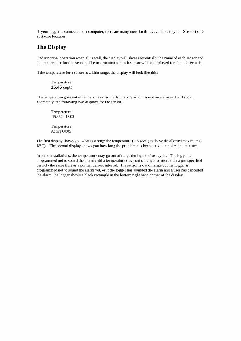
If the temperature for a sensor is within range, the display will look like this:
Temperature15.45 degC
If a temperature goes out of range, or a sensor fails, the logger will sound an alarm and will show,alternately, the following two displays for the sensor.
Temperature-15.45 > -18.00
TemperatureActive 00:05
The first display shows you what is wrong: the temperature (-15.45°C) is above the allowed maximum (-18°C). The second display shows you how long the problem has been active, in hours and minutes.
In some installations, the temperature may go out of range during a defrost cycle. The logger isprogrammed not to sound the alarm until a temperature stays out of range for more than a pre-specifiedperiod - the same time as a normal defrost interval. If a sensor is out of range but the logger isprogrammed not to sound the alarm yet, or if the logger has sounded the alarm and a user has cancelledthe alarm, the logger shows a black rectangle in the bottom right hand corner of the display.

EL005 Logger without display
The EL005 logger has no display or buttons, and so it can only be used with a computer.
The EL005 does not have an internal alarm: if you need an audible alarm, connect an EL006 audible alarmunit to the network.
Connections
The logger has four sockets on one end:
• a round DC power socket: the cable from the mains adapter supplied with the logger plugs in here.• two square network sockets
• a D-shaped serial port socket which connects either to a computer serial port or to a printer usingthe serial port adapter supplied.
The logger also has a red light (LED) next to the serial port.
Batteries
The EL005 logger has internal re-chargeable batteries. These batteries are kept topped up whilst mainspower is available, and will keep the system running for up to 24 hours during a mains power failure. TheEL018 dialer adapter/battery backup can provide power to the system for much longer periods in theevent of mains failure.
You should check the batteries at least once a year, and replace them if they cannot keep the loggergoing on standby for a satisfactory period.
The unit switches to battery power as soon as the mains power is disconnected, so it will take some timefor the batteries to recharge after a long period without mains power.
LEDWhen the unit is first powered on, the red light comes on continuously while it carries out a selftest.
If the unit is not configured, the light flashes at a uniform rate, once per second.
If the unit is configured, the light shows traffic on the EnviroMon network: this normally shows as asequence of very short pulses every three to five seconds.

EL006 Remote alarm
The remote alarm is useful when the room where the logger is located is not often occupied. One or moreremote alarms can be connected at any place along the network where staff will hear the audible alarm
The remote alarm looks like a standard converter, but has only the network sockets. It is connected tothe system using two networkextension cables.

EL011 Alarm relay
The alarm relay can be used to turn on or off an electrical circuit when an alarm occurs. This could, forexample, be used to control a warning lamp or siren. The relay contacts are rated at 250V at 1A: the unitcan therefore be used to control mains equipment.
The unit is supplied in an IP65 enclosure. It is fitted with five cable glands: network in and out, mains inand two mains out. The unit is supplied with a stopper in each cable gland: for unused cable glands, thestopper can be left in place.
The alarm relay can be connected to the network using either telephone connectors or screw terminals:if you wish to use telephone connectors, the cable glands should be removed.
The relay has two sets of contacts. Each set of contacts has one normally-closed contact and onenormally-open contact. There are two spare pairs of screw-terminals which are unconnected: these canbe used to connect neutral and earth wires.
Safety note: If you are using the alarm relay to control mains electricity, the unit should be installed bya qualified electrician.
The following diagram shows how to connect a single mains device (for example a siren) so that it isturned on when an alarm occurs.
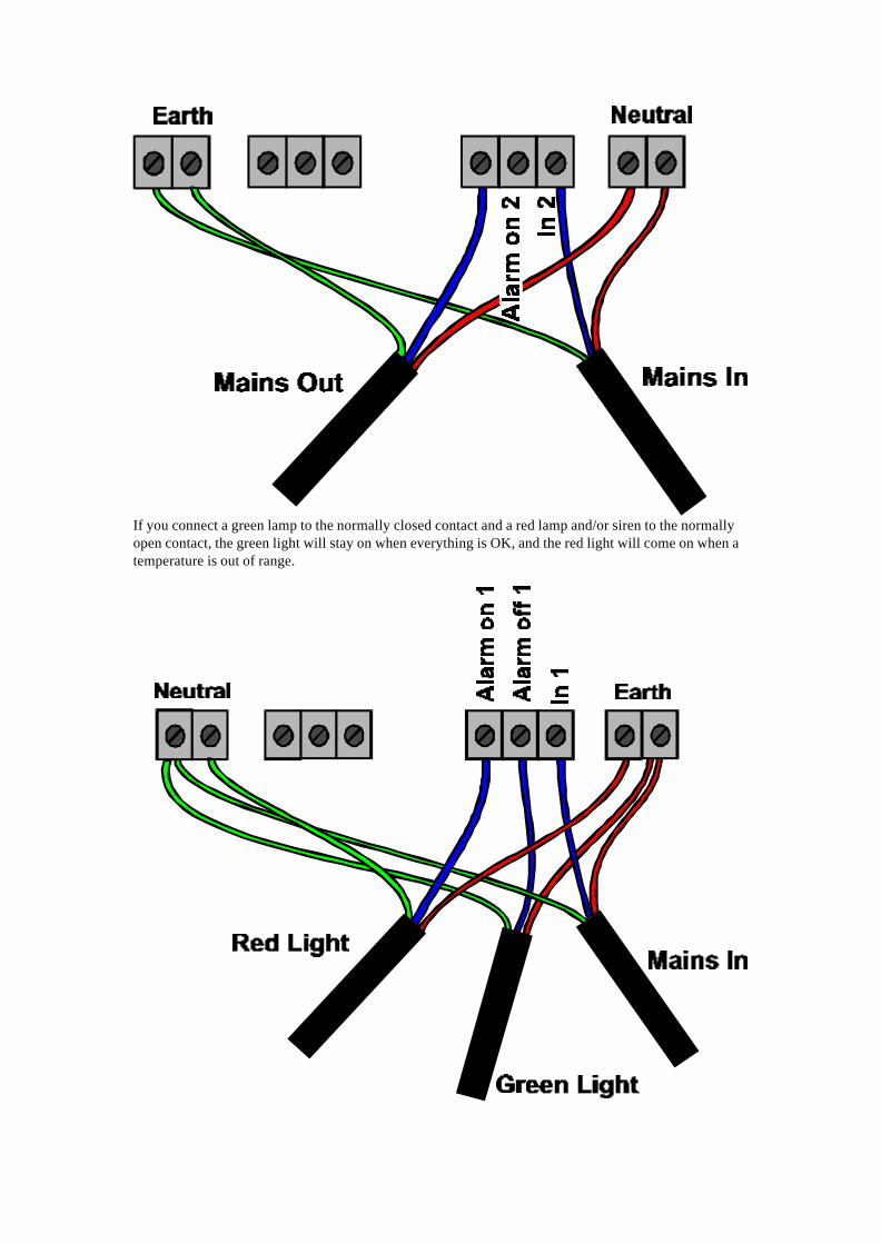
If you connect a green lamp to the normally closed contact and a red lamp and/or siren to the normallyopen contact, the green light will stay on when everything is OK, and the red light will come on when atemperature is out of range.

EL018 Dialer adapter/battery backup
The EnviroMon system is designed to operate with the Gardiner Technology Gardtec dialer or theMenvier Security SD1 Speech dialer. The system can also work with other dialers by connecting themvia the EL011 alarm relay unit.
The dialer can be programmed with a list of emergency telephone numbers. When there is a problem, thedialer calls each of the telephone numbers in turn until someone answers, then it gives a messagesaying that there is a problem.
The dialler behaves in the same way as any normal extension and does not affect the normal operationof the telephone.The dialer adapter serves three purposes:
• it controls the dialer• it provides power for the dialer and for the system• it can provide battery backup for much longer periods than the logger's internal backup
The dialer adapter is supplied in a grey plastic box with a clear lid. The box has a large hole each side forcables. There is space for a 1.2AH battery inside the box: this will provide backup for 12 to 24 hours,depending on the configuration. Alternatively the unit can be connected to a car battery outside thebox: this could provide backup for many days.
Safety note: When using an 1.2AH battery inside the box, do not attempt to seal the cable holes, asthis may cause an explosive build-up of gases inside the box.
The Speech Dialer can give three messages for different types of problem as follows:
• A - temperature out of range or sensor fail• B - mains fail for more than 5 minutes• C - network fail for more than five minutes.
There is a separate wire between the adapter and the dialer for each problem: if you do not wish to havecalls made about a problem, leave the wire unconnected.
There is a red light for each problem: the light is turned on when the problem is detected. There are twogreen lights- one for mains power and one for battery power. When the mains is on the battery is keptcharged up continuously and both the mains and the battery lights remain on.
There are three groups of screw terminals on the EL018: these serve the following purpose:
• backup battery• speech dialer• network (you can use the phone connector sockets if you prefer).
When using the EL018, the mains adapter plugs into the EL018 and not the logger: the logger ispowered from the EL018 via the network cable.
The connectors and lights on the EL018 are laid out as follows:

When it is wired into the system, it will look like this:

Chapter 4: Getting started
Identifying the equipmentInstalling the softwareSetting converter addressesCalibrating humidity convertersConnecting the equipmentConfiguring the systemLooking at current readingsDisplaying a graph

Identifying the equipment
You will need the following equipment in order to set up a simple test system:
ComputerThe computer must be running Windows 3.1, 95,98,ME,NT or 2000. It must have at least one spare serialport
Serial portThis is a D-shaped male (with pins sticking out) socket on the back of your computer. The socket canhave either 9 or 25 pins: if the socket has 25 pins, you will need to use a D9-to-D25 adapter. Mostcomputers have only two serial ports- these are called COM1 and COM2. The ports are not normallylabelled, but it is usually safe to experiment to find out which is which.
D9-to-D25 adapterThis is supplied with the EnviroMon system: it is only needed if your computer has a 25-pin serial port.
Serial cableThis is a cream-coloured round cable about 2 metres long with D-shaped 9-pin connector at each end.The male end (the one with pins sticking out) connects to the logger: the female end attaches to theserial port on the computer.
Mains adapterThis is a black plastic block with a built-in mains plug. It has a black two-core cable that goes to a roundDC connector, which plugs into the power socket on the logger.
LoggerThe logger collects data and stores it until the PC is ready to receive it. There are two types of logger-the EL005 (grey box) and the EL008 (black box with a display). The logger has the following connectors:• round DC connector to mains adapter• D9 female connector to computer• two square telephone-style connectors for networkThe two network connectors are joined internally, so you can use either socket, or both.When you connect power to the EL008, it shows some version information on the display. When youconnect power to the EL005, the red light comes on for a few seconds and then starts flashing.
Network cableThis is a white oval cable about five metres long with telephone-style connectors at both ends. Notethat network connectors are slightly larger than sensor connectors. Network connectors have six slotsin the end, although only the middle four slots are fitted with gold contacts.
ConverterThe converter changes the electrical signal from a sensor into a digital message that is transmitted to thelogger. There are several types of converter: the most common is the EL001 temperature converter. TheEL001 is a black plastic ‘soap box’ with two square network sockets at one end and three sensorsockets at the other end.Each converter has an ‘address’- a number between 1 and 15, which is used to identify the converter.The address appears on the top left hand corner of the converter.
Temperature sensorPico supplies several different types of temperature sensor: the most common are the EL015 and theEL039. The EL015 or EL039 temperature sensor is a stainless steel tube, 6mm diameter and 50mm long. Itis fitted with a white, oval cable about five metres long, with a telephone style connector on the otherend.The sensor connector is slightly smaller than the network connector: it has four small slots, eachcontaining a gold contact- unlike the network connector, which has an empty slot at each end.

There is a clear plastic label on the cable next to the connector: this specifies the type of sensor (egEL015), the batch number and the sensor number. The batch number and serial number are unique foreach sensor, and can be used as a reference number for calibration information.
See also: Connecting the equipment
Installing the software
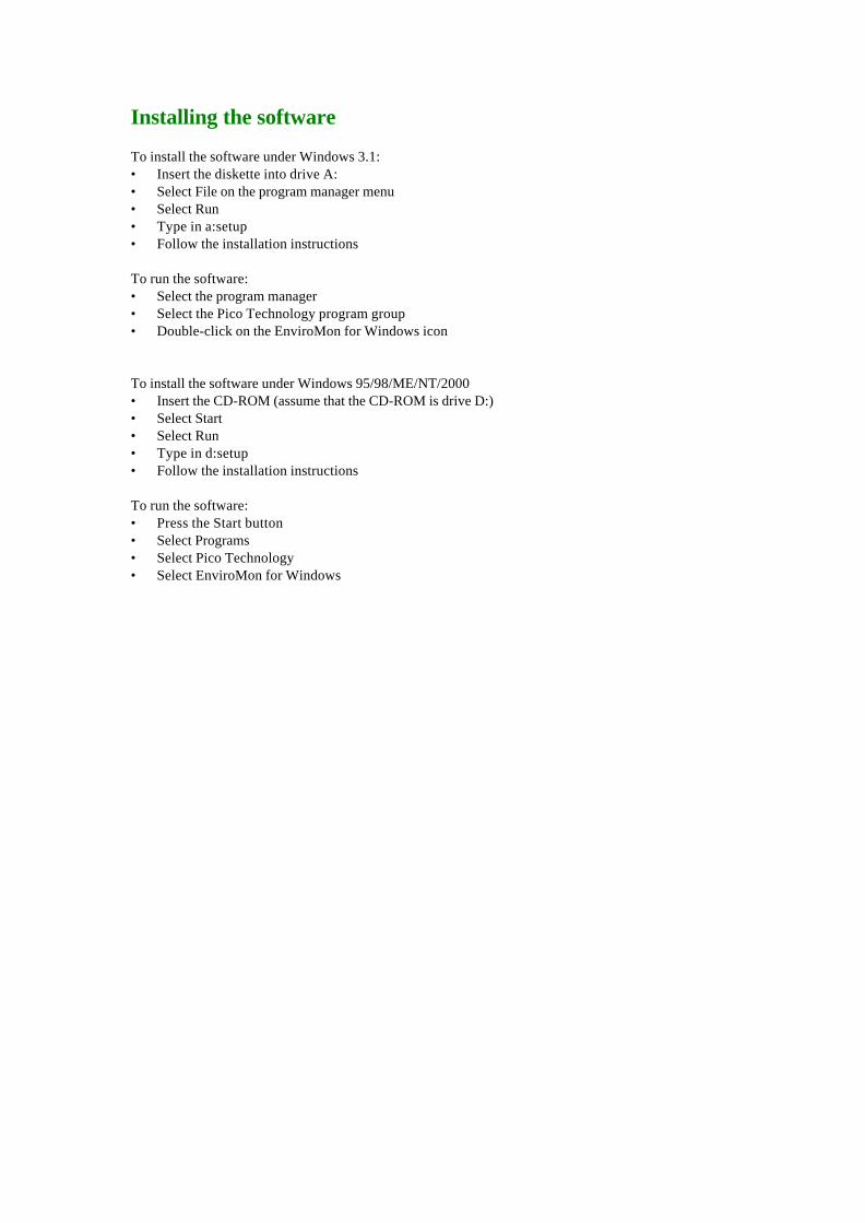
To install the software under Windows 3.1:• Insert the diskette into drive A:• Select File on the program manager menu• Select Run• Type in a:setup• Follow the installation instructions
To run the software:• Select the program manager• Select the Pico Technology program group• Double-click on the EnviroMon for Windows icon
To install the software under Windows 95/98/ME/NT/2000• Insert the CD-ROM (assume that the CD-ROM is drive D:)• Select Start• Select Run• Type in d:setup• Follow the installation instructions
To run the software:• Press the Start button• Select Programs• Select Pico Technology• Select EnviroMon for Windows

Setting Converter Addresses
Note: you can skip this section if you have only one converter- for example, if you are using a starter kit.If you are planning to use more than one converter, each converter must have a different address.Most converters has the address written on the top right hand corner. If you have two converters withthe same address, you must change the converter addresses so that each converter has a uniqueaddress BEFORE you connect up the complete network. To do this:
• Install the software on your computer • Connect the logger to a serial port on the computer using the cable provided• Plug the power supply into the mains and connect it to the logger• connect the first converter to the logger using the network cable • Press the Start button (Win95 and above)
• Select Programs• Select Pico Technology• Select Set Converter Address
• Select the serial port (eg COM2) that you connected the logger to• Select the address that you wish to use for this converter• Press the Program button• Wait until the computer reports that the converter has been programmed• For EL026 humidity converters, see Calibrating humidity Converters• Unplug the converter• Repeat this procedure for each converter
See also:Identifying the equipmentConnecting up the equipment

Calibrating humidity Converters
If you are not using humidity converters, you can skip this section.The EnviroMon humidity measuring system is made up of two parts- the EL026 converter and the EL030sensor. These can be connected together using a cable up to 25 metres long.The EL030 sensor has some calibration information written on the base: before you use an EL026 andEL030 together, you should use the Converter Address program to write this calibration information intothe EL026.
To do this, you should connect up the equipment and run the Change Converter Address program asper the instructions for setting the converter address, then you should proceed as follows:
• Select the serial port (eg COM2) that you connected the logger to• Select the address that you wish to use for this converter• Press the Program button• Wait until the computer reports that the converter has been programmed• The computer will turn on the Calibration button: press this button now• Enter the lowest figure (normally about 0%) into the first box• Enter the highest figure (normally about 100%) into the second box• Press the Program button• Wait until the computer reports that the converter has been programmed• Unplug the converter
See also:Setting converter addresses

Connecting up the equipment
To gain experience with the system, we recommend connecting up a small system, with just a singleconverter, next to the computer. Once you are confident that you understand how it works, you caninstall the complete system in the correct place.
Logger to PCConnect the logger to a serial port on the computer using the serial cable. It may be necessary to use theD9 to D25 adapter as well.
PowerPlug the mains adapter into a mains socket and then plug the DC connector into the logger
NetworkPlug one end of the network cable into the logger, then plug the other end into one of the networksockets (labelled Net) on the converter
SensorPlug the temperature sensor into the first sensor socket (labelled Ch1) on the converter
You are now ready to start the software and then configure the system.
See also:Identifying equipmentConfiguring the system

Configuring the system
To run the software:• Press the Start button• Select Programs• Select Pico Technology• Select EnviroMon for Windows
The first time you start up the software, it will offer you three choices:• a look at the overview section of the help file• a guided tour of the configuration• start the configuration
If you select the guided tour, the computer will take you through the basics of setting up the system,explaining what each step involves. Alternatively, you can follow the instructions below.If you are not in the configuration control panel already:• select Settings from the Main menu• select Configuration from the Settings menu
You should now be at the configuration control panel. If you have already configured the system, andwish to start again:• click on Reset• when the computer asks you to confirm, Click on Clear
Once you are back at the configuration control panel, it is time to set the sampling rate:• Click on General• Click on Sampling• set the Minutes per Reading field to the required value• Press OK• Press OK
Now we find out what equipment is connected.• Click on Equipment• Set the serial port field to the one that the logger is connected to (eg COM2)• Click on Converters• Click on Auto-configure• a box will appear and will show you the status of the auto-configure process. After a few seconds,
this will disappear and the computer should display the details of your converter in the large box.• Click on OK• Click on OK
Now we need to specify where the sensors are to be located, by giving names to them.• Click on Locations• Click on Add• Type in a name for your sensor into the Name field• Select the channel that you wish to use (channel 1 on your converter)• Select the type of sensor, for example EL015.• Click on OK
Now we need to program the calibration information into the logger.• Click on Program• a box will appear and will show you the status of the auto-configure process. After a few seconds,
this will disappear if the programming completed successfully.
The configuration is complete: we must exit from the program now so that the changes will take effect.• Click on Exit• Click on OK

If you have an EL008 logger, the readings should appear on the display after 20-30 seconds. If you havean EL005, you will need to restart the software to display the readings.

Looking at current readings
To look at the current readings, you should start the EnviroMon for Windows program:• Press the Start button• Select Programs• Select Pico Technology• Select EnviroMon for WindowsIf it is more than a few minutes since you last ran the software, the computer will display a box to showyou how many readings it has transferred from the logger.The computer next displays the monitor view - a list of temperatures for each sensor.From the monitor view, you may find the following features useful:
• Select Settings then Configuration to make changes to the configuration• Select View... then another option to view stored data• Select Help then Contents to get the help file contents page• Select Help then Index to get an index for the help file
• Select Help then Guided tour for a guided tour of the functions used in day-to-day operation.
See also:Monitor viewDisplaying graphs
Displaying a graph
To look at the graph, you first need to display the monitor view.Next you should take the following steps:• Select View from the main menu• Select Graph from the View menuThe computer will display a graph showing all data recorded so far.
See also:Graph view
EL014/ EL019 Printer
If you do not wish to connect a computer to the logger, you can connect it directly to a printer. Theprinter connects to the serial port on the logger, using the adapter provided. EnviroMon has beentested with the following types of printer:
Printer part number Adapter part number Printer Paper formatEL014 EL023 Datac 1100 40 column tally rollEL019 EL024 Epson LX100 80 column A4 paper


![L7 SERIES SYSTEM - A2V · L7 SERIES SYSTEM Servo Drive Designation PEGA PEGASUS Series-A R5 Flange Size A : 40 Flange B : 60 Flange A Motor Capacity R5 : 50[W] 01 : 100[W] 02 : 200[W]](https://img.dokumen.tips/doc/110x75/5fbf5c9f70a7e12f161eb292/l7-series-system-a2v-l7-series-system-servo-drive-designation-pega-pegasus-series-a.jpg)