Embed Size (px)
Citation preview

The Enerjetik RJ2 Gasifier
Do we finally have the right gasifyingsystem for the Ceramic Industry?
National Brick Research Center & ACerS Structural Clay Division Meeting
May 13-14, 2013
Christophe Aubertot - Direxa Engineering, LLC 1 ACerS SCPD / NBRC joint meeting May 2013

Index
2
Introduction to gasification Description of system Performance rangeWhat’s next
May 2013

Introduction to Gasification
3
Basic Principle:Conversion of any carbonaceous fuel into a gaseous product with a usable heating value (excluding combustion)
C + H2O → CO + H2 (syngas)This syngas can be sent to a spark ignition internal combustion engine or power a turbine to produce electricity or it can be burned like we burn Natural Gas in our industry.We will limit the subject in this presentation to burning of syngas in a burner for ceramic firing application.
May 2013
Introduction to Gasification
4
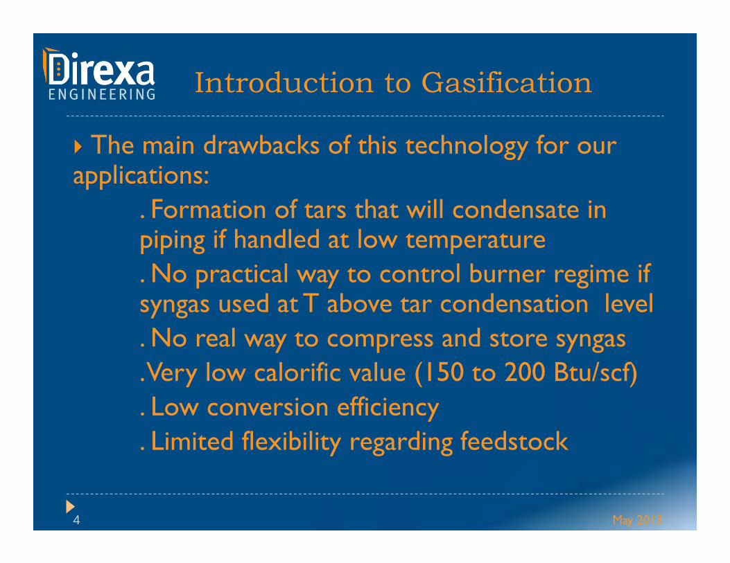
The main drawbacks of this technology for our applications:
. Formation of tars that will condensate in piping if handled at low temperature. No practical way to control burner regime if syngas used at T above tar condensation level. No real way to compress and store syngas. Very low calorific value (150 to 200 Btu/scf) . Low conversion efficiency. Limited flexibility regarding feedstock
May 2013

Introduction to Gasification
5
Why then be interested in this technology? Because the RJ2 system solves all the problems above, and some…..
Because it can help take advantage of the Environment Protection Agencies incentives of certain countries
Because in most of these countries the price of natural gas makes syngas very attractive economically. Who knows, one day it might even happen in the USA…
May 2013

Description - System Principle
6 May 2013
• Feedstock is introduced into machine• Feedstock is gradually heated in oxygen
free environment (pyrolysis phase) to drive off volatiles and create uniform Carbon Char
• Burner is designed to use fuel and steam with small amount of O2 (or air) to create Heat and produce Syngas
• Carbon char is reacted in the heat to create more product Syngas and Ash
• Ash / Syngas are separated in a cyclone• The Syngas exits the top of the cyclone
to be used for energy• Ash settles out of the cyclone, is augured
out, and collected for recycling

Description - advantages
7
The feed stock is heated to bellow 800 deg C in the Pyrolyser (typically 300-400 deg C). At temperatures above 800 deg C exotic corrosion occurs, especially in a reducing environment.
Water driven off in the Pyrolysing stage is used in the flash pyrolysis stage, reducing the need to generate steam for the water gas reaction.
The Flash Pyrolyser can utilise oxygen and so reduces the amount of nitrogen in the Syn Gas, giving the gas a higher CV and reducing the opportunity of NOxformation when the producer gas is used.
May 2013
Description - advantages
8
The flash pyrolysis system stops the formation of tars, the producer gas is clean and tar free so it does not need down stream cleaning.
The combination of flash pyrolysis and the water gas reaction in the reactor is very energy efficient and stops the need for oxidation to occur to provide the temperature for the gasification reaction to occur, this reduces the amount of CO2 in the produced gas to 20%.
As the system is a pressure vessel system and not a fluidised bed gasifier down draft system, slagging or softening of the ash does not occur.
May 2013

Description - advantages
9
The Cyclone post reactor is a positive pressure cyclone, which means all particulates are forced out the bottom, rather than using gravity to drop out of the gas stream.This removes the risk of slagging on the gas take off route.
The water/gas reaction continues to occur in the cyclone, cooling the ash so that it is safe to remove.
The lack of nitrogen and the fast cooling of the gas and the ash stops the formation of dioxins.
May 2013

Description - advantages
10
The producer gas thus has a high CV and is clean, and can be used in gas engines.
The residence time required for the pathogen “kill” occurs in the cyclone, this is very easy to model and prove, removing one of the major obstacles in consenting.
Utilises pressure to move fuel and gas and so has a small amount of moving parts and is very interesting for kiln syngas distribution / storage
Producer gas does not require clean up and so reduces capital cost and foot print.
May 2013

Description - advantages
11
Small thermal mass of plant, it is estimated that the 100 tons / day plant can go from cold to running in around 30 to 45 minutes.
Can accept all kinds of feedstock, as we will see further one.
Ash contains Carbon that can be mixed with the brick body at extrusion
May 2013

1st pilot plant / 2nd Generation
12 ACCSCD / NBRC joint meeting May 2013

2nd Pilot - Description of system
13 May 2013

Feed Stock Weighing
14 ACCSCD / NBRC joint meeting May 2013

Feeding the Beast
15 ACCSCD / NBRC joint meeting May 2013

Conditioning the Feed Stock
16 ACCSCD / NBRC joint meeting May 2013

Air Lock
17 ACCSCD / NBRC joint meeting May 2013

Into the pyrolizer
18 ACCSCD / NBRC joint meeting May 2013
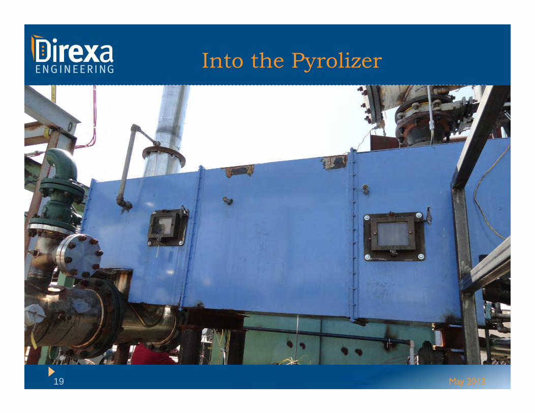
Into the Pyrolizer
19 May 2013

Into the Flash Reactor
20 ACerS SCPD / NBRC joint meeting May 2013

Into the Cyclone
21 May 2013

Ash Recovery
22 ACCSCD / NBRC joint meeting May 2013

Heat exchanger
23 ACCSCD / NBRC joint meeting May 2013

Flare
24 May 2013

Performance – Ex #1
25 May 2013
Shredded Tire Feedstock
Hydrogen 42%Carbon Monoxide 25%Methane 16.5%Carbon Dioxide 11%Ethylene 4%Nitrogen 1.5%
Specific Gravity .5827 BTU / cu ft 445

Performance – Ex #2
26 May 2013
Shredded Wood Feedstock
Hydrogen 42%Carbon Monoxide 26%Methane 6.5%Carbon Dioxide 19.7%Ethylene 1.9%Nitrogen 1.5%
Btu / cu ft 440

Performance – Diagram
27 May 2013
Efficiency: 72 to 88% + Carboneous ash
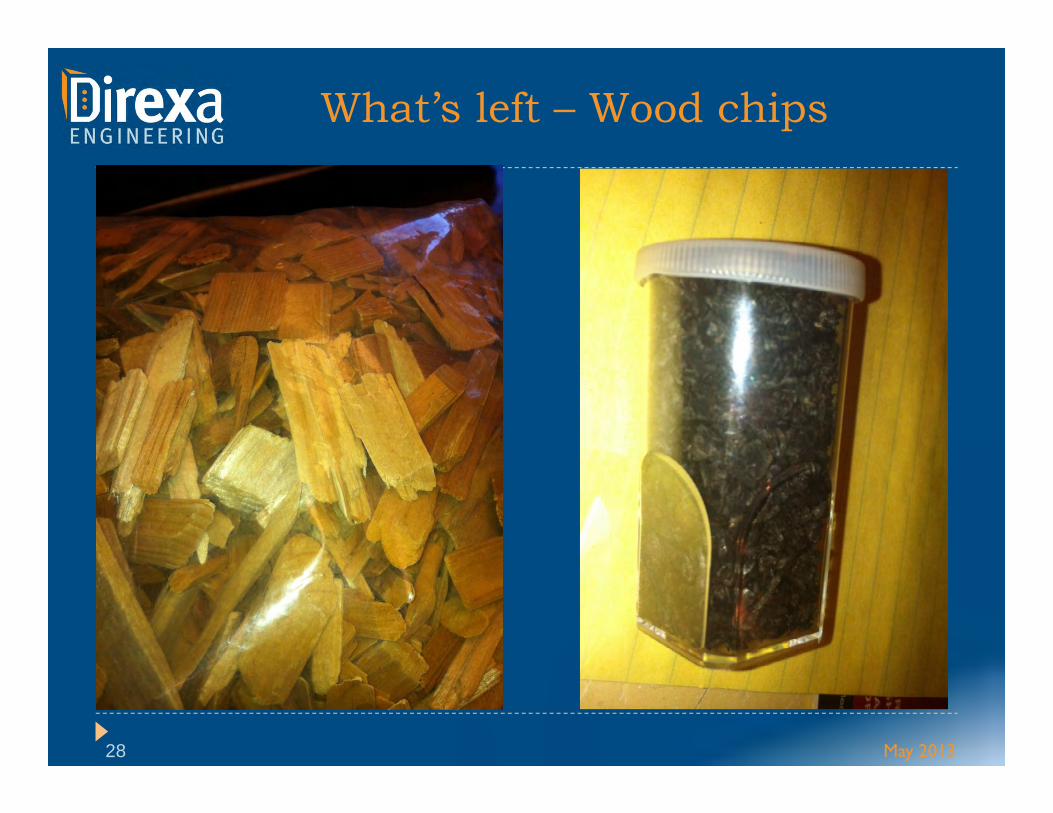
What’s left – Wood chips
28 May 2013

What’s left - tires
29 May 2013

What’s next?
30
72 hrs continuous test of two feed stocks: Municipal Waste – English project for production of electricity.
Construction Waste Timber – Overseas Brick Kiln application.
Sewer sludge was also envisioned (absolutely possible but won’t happen this time)
Scheduled to happen within a month.
May 2013


![FLEX FUEL GASIFIER SIMULATION MODEL [FFGSM]mypages.iit.edu/~abbasian/documents/ffgsm_user_manual.pdf · 6) Gasifier Tab: This tab opens the Gasifier Panel where the gasifier input](https://img.dokumen.tips/doc/110x75/5eb664fad746ec31aa42c957/flex-fuel-gasifier-simulation-model-ffgsm-abbasiandocumentsffgsmusermanualpdf.jpg)