Embed Size (px)
Citation preview

design machine groupUniversity of Washington
Seattle WA USA 98195-5720http://depts.washington.edu/dmachine
The Electronic Cocktail Napkin - computer support for working withdiagrams
Gross, M. D
Design Studies. 17(1), 53-70z
1996
Electronic Cocktail Napkin 1
The Electronic Cocktail Napkin -
A computational environment for working with design diagrams
Abstract
The Electronic Cocktail Napkin is an experimental computer-based environment for
sketching and diagramming in conceptual design. The project's goal is to develop a
computational drawing environment to support conceptual designing in a way that leads
smoothly from diagrams to more formal and structured representations of schematic
design. With computational representations for conceptual designs, computer supported
editing, critiquing, analysis, and simulation can be employed earlier in the design process,
where it can have a greater impact on outcomes. The paper describes the Electronic
Cocktail Napkin program -- its recognition and parsing of diagrams and management of
spatial constraints, its drawing environment, and two experimental query by diagram
schemes for retrieving information from architectural databases.
Introduction
Incremental formalization from diagrams to drawings
During conceptual design a wide range of alternatives are quickly considered and
compared. The designer works abstractly and without commitment, employing diagrams
and sketches to represent the design situation and to explore alternative solutions. Because
diagrams are abstract, the designer can avoid thinking prematurely about details. Because
diagrams are quick and easy to make, the designer can rapidly explore a variety of solution
types without the effort and commitment of making more careful drawings.
Electronic Cocktail Napkin 2
Designers proceed from a conceptual diagram to develop more specific, detailed, and
committed schematic drawings. Information in these drawings is richer and more complex,
yet the schematic drawing will typically contain many of the same elements and relations
present in the original diagram. As designing proceeds the schematic drawing is developed
further, becoming more specific, detailed, and committed. The final drawings that specify
the designed artifact for construction or manufacture are characterized by full commitment
and there is little room for ambiguity or abstraction.
Working from abstractions to specific details with increasing commitment and precision,
design is a process of incremental formalization. The space of design alternatives is
defined and circumscribed by constraints that specify design qualities, quantities, and
spatial relationships. Thus, we can think of designing as a process of adding constraints
and exploring the design space they bound. At the outset, a design space can be described
by a few elements and relations, which can be illustrated in a simple diagram. For example
in a floor plan the set of functional spaces, and their size and adjacency requirements
constitute constraints that can be expressed in a bubble diagram. As designing progresses
to the schematic phase these same constraints still obtain while other more detail level
constraints are added. For example, relationships between sizes and positions of doors and
windows, the thickness of walls, and three dimensional considerations are added to the
design constraints. The crude bubble diagram is no longer a sufficient representation for
the design, and it must be developed or replaced by a schematic drawing that can illustrate
these new properties and relationships.
Computer support for diagrams
Computer-aided design (CAD) representations have for the most part ignored this
progression from abstract and low-commitment diagrams to detailed, specific, and higher-
Electronic Cocktail Napkin 3
commitment drawings. CAD tools support only the later phases of designing, that is,
making schematic and working drawings. They require the designer to identify design
elements and relationships specifically and precisely, rather than at the level of abstraction
used in conceptual design. Therefore many good designers stick with pencil and paper to
make early explorations, and bring their designing to the computer only after the work
reaches a stage appropriate to the effort, commitment, and precision that CAD demands.
Two obstacles work against thinking quickly and abstractly with today's CAD software:
precise and structured internal CAD representations and tedious mouse-based human-
computer interfaces. First, the internal representations of most CAD programs are not
amenable to abstraction or ambiguity. Elements must be identified precisely, and
positioned, sized, and related to other design elements in specific ways, so it is difficult for
a designer to postpone making precise and particular decisions. Second, most human-
computer interfaces in CAD programs employ menus or tool palettes, which demand more
effort than is appropriate for expressing an idea that the designer may hardly be committed
to. For example, in a typical CAD program, drawing a circle takes three steps: select the
circle tool, point out a center, and identify a radius. The resulting circle is highly precise
with a specific position, size, and shape, as well as line weight and color; however the
designer may not particularly intend these properties. The CAD program's interface makes
the designer work too hard and its precise representation for designs pushes the designer
into specific commitments before she is ready to make them.
These two obstacles suggest the approach to computer supported conceptual design
followed in the Cocktail Napkin project. First, adopt a paper-like, or pen-based, interface
that allows designers to draw directly what they have in mind, with varying degrees of
precision, ambiguity, and abstraction. Second, provide internal representations that can
tolerate ambiguity and incompleteness, yet which can be made more formal and structured

Electronic Cocktail Napkin 4
as designing proceeds. The Cocktail Napkin's pen-based interface provides an
unstructured and direct drawing environment that enables designers to begin working with
a computer at an early stage of thinking. By providing facilities for recognition, parsing,
and constraint management, the Cocktail Napkin enables the designer to move gradually
from unstructured diagrams toward more formal and structured CAD representations.
The remainder of the paper is organized as follows. Section 2 describes the Cocktail
Napkin's facilities for recognizing and parsing diagrams as visual language expressions.
Section 3 gives an overview of the Cocktail Napkin drawing environment, including its
features for simulated tracing paper and a shared drawing surface for collaborative work.
Section 4 describes two prototype systems of diagram-based query and retrieval, which
suggest how a drawing environment can be linked to knowledge-based tools. Section 5
reviews related work in diagrams and design, and Section 6 concludes with a brief
summary, a discussion of issues raised, and directions for further work.
2. Recognition & parsing
Drawing programs that emulate pen and ink, pastel, and watercolor are an alternative to
highly structured CAD programs. These programs, which often employ pen-tablet
technology, offer designers highly realistic computational surrogates but they do not
significantly enhance design. Although these programs offer exquisite visual
representations, they do not convey information about the structure -- the elements and
relations -- of the design. Without a representation of the design's structure the computer
can do little more than paper and pencil. Therefore a program that supports hand-drawn
drawing for design must have capabilities for recognition and parsing.

Electronic Cocktail Napkin 5
The Cocktail Napkin program supports recognition and parsing in a three-step process.
First, the program recognizes hand-drawn multi-stroke symbols, or glyphs, drawn on a
tablet. Second, it analyzes spatial relations among diagram elements. Third, it matches
elements and relations it finds against previously defined configurations, thereby parsing
the diagram. At each level the recognition and parsing process tolerates ambiguity and
incompleteness, allowing the designer to work initially with unidentified forms and
configurations and gradually identify them as design progresses toward the schematic
phase.
Recognizing Diagram Elements
The Cocktail Napkin reads hand drawn symbols, or glyphs from a Wacom digitizing tablet
at 1200 baud. A raw glyph read from the tablet consists of a sequence of x,y, and pressure
values, terminated when the designer lifts the pen from the tablet for longer than a
(variable) time-out period. This permits the designer to make multi-stroke glyphs. A
typical glyph contains 20-40 points, depending on its size and speed at which it was
drawn. The first processing step counts strokes, identifies the glyph's bounding box, its
size relative to the drawing surface, aspect ratio, corners, and pen path. The pen path is
represented as a sequence of integers 1-9 that describe the pen's movement through a 3x3
grid inscribed in the bounding box. The program identifies x,y points that are close
together as corners, where the pen slowed to start, stop, or round a corner, or where two
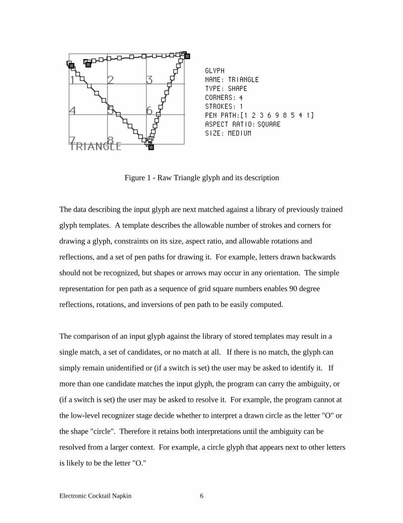
strokes crossed. Figure 1 shows a triangle glyph and its raw data.
Electronic Cocktail Napkin 6
Figure 1 - Raw Triangle glyph and its description
The data describing the input glyph are next matched against a library of previously trained
glyph templates. A template describes the allowable number of strokes and corners for
drawing a glyph, constraints on its size, aspect ratio, and allowable rotations and
reflections, and a set of pen paths for drawing it. For example, letters drawn backwards
should not be recognized, but shapes or arrows may occur in any orientation. The simple
representation for pen path as a sequence of grid square numbers enables 90 degree
reflections, rotations, and inversions of pen path to be easily computed.
The comparison of an input glyph against the library of stored templates may result in a
single match, a set of candidates, or no match at all. If there is no match, the glyph can
simply remain unidentified or (if a switch is set) the user may be asked to identify it. If
more than one candidate matches the input glyph, the program can carry the ambiguity, or
(if a switch is set) the user may be asked to resolve it. For example, the program cannot at
the low-level recognizer stage decide whether to interpret a drawn circle as the letter "O" or
the shape "circle". Therefore it retains both interpretations until the ambiguity can be
resolved from a larger context. For example, a circle glyph that appears next to other letters
is likely to be the letter "O."
Electronic Cocktail Napkin 7
Analyzing spatial relations
A diagram consists not only of a collection of recognizable elements; they are also arranged
in certain spatial relations. The next recognition stage identifies spatial relations in the
diagram. The Cocktail Napkin's analyzer applies a stored set of binary predicates to
identify spatial relations such as containment, above, below, right and left-of, line
intersections, crossings, and tees. Because diagrams are by nature imprecise, a small
number of qualitative spatial relations suffice.
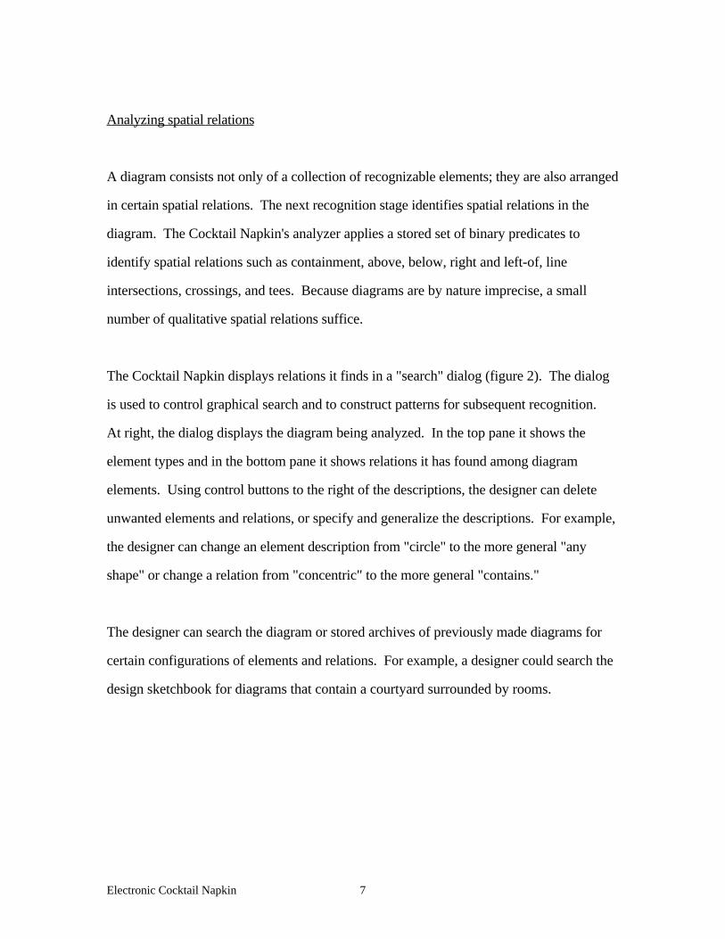
The Cocktail Napkin displays relations it finds in a "search" dialog (figure 2). The dialog
is used to control graphical search and to construct patterns for subsequent recognition.
At right, the dialog displays the diagram being analyzed. In the top pane it shows the
element types and in the bottom pane it shows relations it has found among diagram
elements. Using control buttons to the right of the descriptions, the designer can delete
unwanted elements and relations, or specify and generalize the descriptions. For example,
the designer can change an element description from "circle" to the more general "any
shape" or change a relation from "concentric" to the more general "contains."
The designer can search the diagram or stored archives of previously made diagrams for
certain configurations of elements and relations. For example, a designer could search the
design sketchbook for diagrams that contain a courtyard surrounded by rooms.
Electronic Cocktail Napkin 8
Figure 2. Search dialog displays spatial relations identified in the diagram
The Cocktail Napkin's analyzer applies relation predicates to pairs of elements in the
diagram. The number of true statements that could be made about any collection of
elements is infinite so the challenge is to identify a small set of relevant relations that can
characterize a diagram. The relation predicates are ordered and restricted in several ways to
limit the program from testing and reporting huge numbers of true, but uninteresting
relationships among elements. For example to limit fruitless testing, predicates lines-
intersect, and lines-tee examine only elements that have been identified as lines. Relations
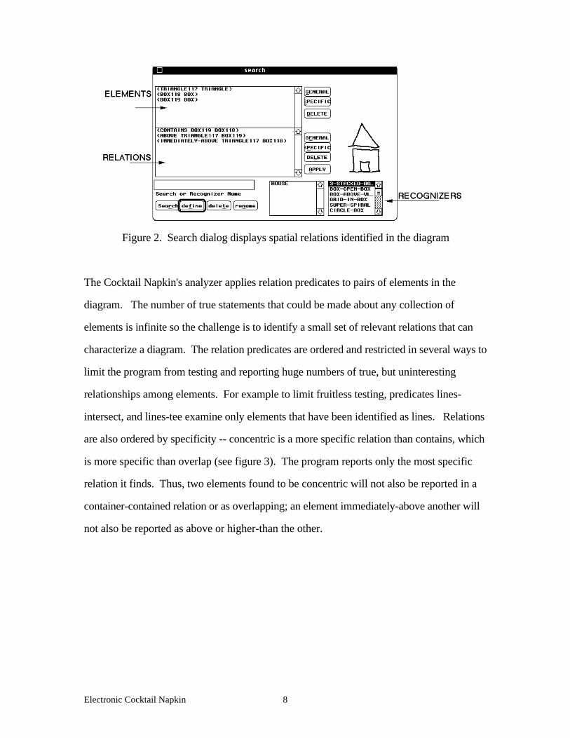
are also ordered by specificity -- concentric is a more specific relation than contains, which
is more specific than overlap (see figure 3). The program reports only the most specific
relation it finds. Thus, two elements found to be concentric will not also be reported in a
container-contained relation or as overlapping; an element immediately-above another will
not also be reported as above or higher-than the other.
Electronic Cocktail Napkin 9
IMMEDIATELY-ABOVE ABOVE HIGHER-THAN
CONCENTRIC CONTAINS OVERLAPPING
more specific less specific
Figure 3 - relations ordered by specificity
In addition the program employs a table of commutative and transitive properties of
relations to restrict the relations it reports. For example, if element A is found above
element B, there is no need to also report that B is below A. Similarly, the transitive
property of relations is used to reduce relation reporting-- if A is left of B, and B is left of
C, then there is no need to also report that A is left of C.
Configurations
After the designer adjusts the description in the search dialog the configuration can be
named and stored for future recognition. (The list of designer defined configuration
recognizers are displayed in the lower right pane of the search dialog.) Whenever the
Cocktail Napkin finds that particular combination of elements and relations, it replaces them
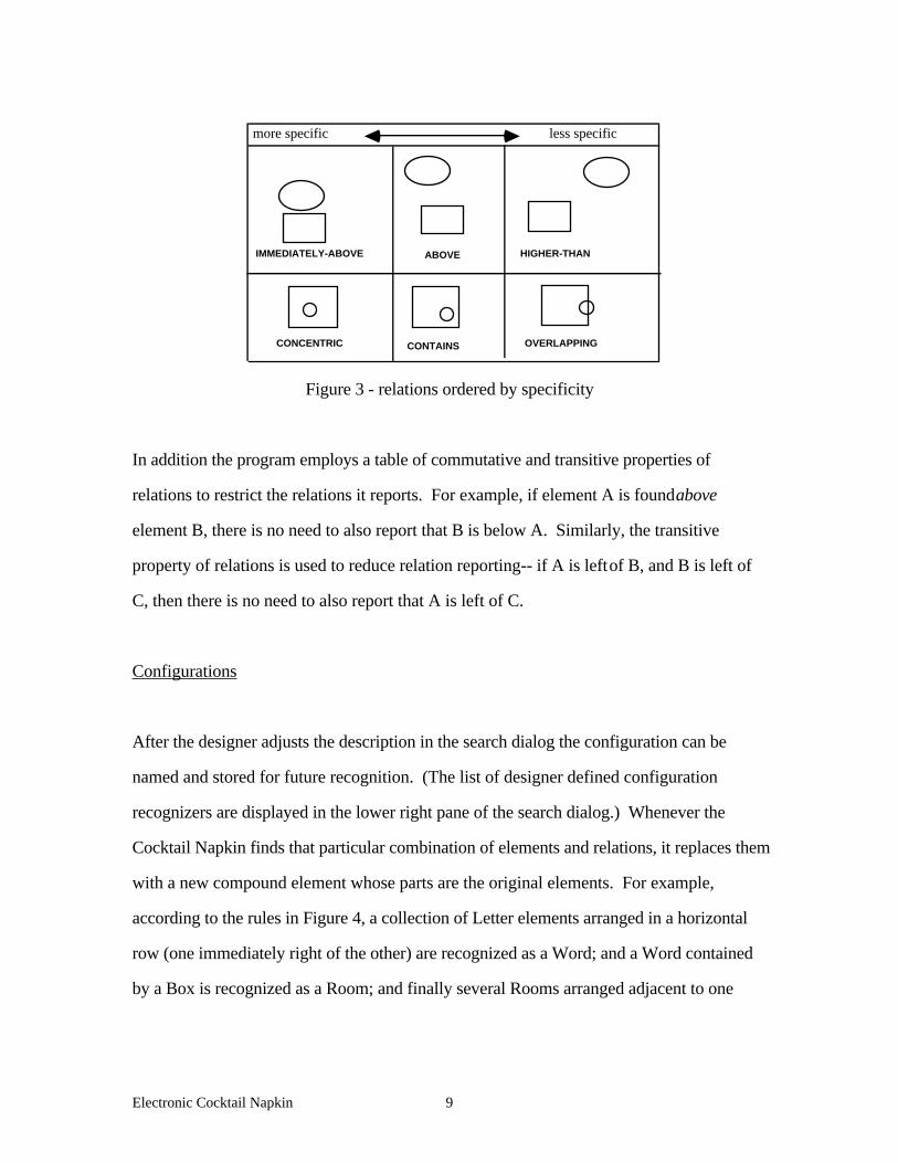
with a new compound element whose parts are the original elements. For example,
according to the rules in Figure 4, a collection of Letter elements arranged in a horizontal
row (one immediately right of the other) are recognized as a Word; and a Word contained
by a Box is recognized as a Room; and finally several Rooms arranged adjacent to one
Electronic Cocktail Napkin 10
another are recognized as a Floor plan. In this way, the designer can build up a set of
replacement rules for recognizing a particular type of diagram.
Floor plan <--- (adjacent Room Room) | (adjacent Room Floor plan)Room <--- (contains Box Word)Word <--- (right-of Letter Letter) | (immediately-right-of Letter Word)
Figure 4. Steps to recognizing a set of adjacent rooms as a 'floor plan'.
The search dialog provides a way to construct a grammar for recognizing diagrams from
basic shapes and relations. However, in contrast to most work on shape grammars (Stiny
1980; Mitchell 1990; Woodbury, Radford et al. 1992), the Cocktail Napkin takes a less
formal, bottom-up approach, and the replacement rules are used for parsing rather than
generating.
3. The Cocktail Napkin Drawing Environment
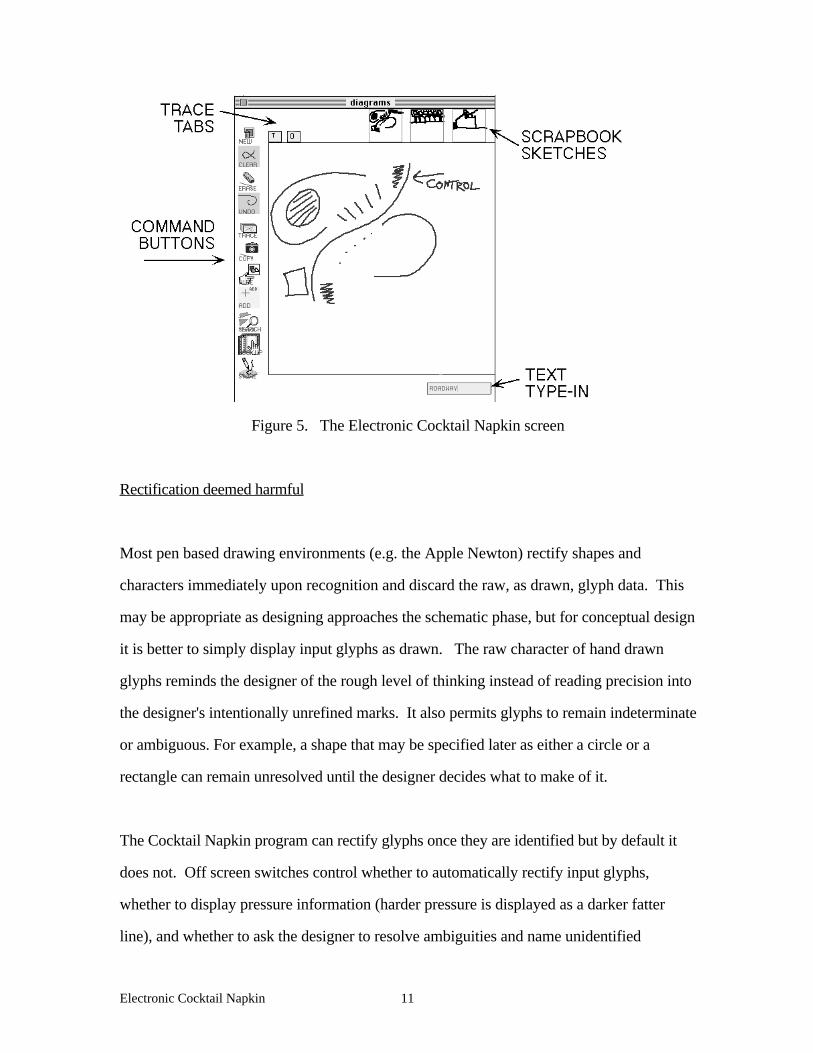
Figure 5 shows the Cocktail Napkin working screen. The designer's drawing appears in
the work area; a text interaction area at the screen bottom displays messages and allows the
designer to type names for new elements; an array of icons at the top show the pages of a
sketchbook of previously made diagrams; trace tabs at the top left enable selection of
various layers of simulated tracing paper, and buttons at screen left provide commands to
clear the screen, hide and remove layers, etc. In addition, commonly used operations
(pick, erase, clear screen, trace overlay, copy) are provided as gestural commands.
Electronic Cocktail Napkin 11
Figure 5. The Electronic Cocktail Napkin screen
Rectification deemed harmful
Most pen based drawing environments (e.g. the Apple Newton) rectify shapes and
characters immediately upon recognition and discard the raw, as drawn, glyph data. This
may be appropriate as designing approaches the schematic phase, but for conceptual design
it is better to simply display input glyphs as drawn. The raw character of hand drawn
glyphs reminds the designer of the rough level of thinking instead of reading precision into
the designer's intentionally unrefined marks. It also permits glyphs to remain indeterminate
or ambiguous. For example, a shape that may be specified later as either a circle or a
rectangle can remain unresolved until the designer decides what to make of it.
The Cocktail Napkin program can rectify glyphs once they are identified but by default it
does not. Off screen switches control whether to automatically rectify input glyphs,
whether to display pressure information (harder pressure is displayed as a darker fatter
line), and whether to ask the designer to resolve ambiguities and name unidentified

Electronic Cocktail Napkin 12
elements as soon as they are drawn. In any case, the designer can rectify (and unrectify)
glyphs on an individual basis.
Maintaining Relations as Constraints
Key elements and relations often carry over as designing moves from the conceptual
representation of diagrams to the more precise and detailed representation of schematic
drawings. The same elements and relationships, though represented more precisely and in
greater detail, are found in later, more developed, drawings. To support this incremental
formalization the Cocktail Napkin enables the designer to establish relations found in the
diagram as constraints on elements of the schematic drawing.
Management of spatial constraints is an old idea in computer aided design, originating in
Sutherland’s Sketchpad program (Sutherland 1963), and it has recently been an area of
interest in CAD. In earlier work I developed a drawing environment for design, called
CoDraw, based on constraints (Gross 1990; Gross 1992). In CoDraw, the designer
explicitly identified spatial relations such as alignments, offsets, and dimensional relations
among drawing elements; then the program maintains the relations during editing. The
Cocktail Napkin automatically identifies constraints on dimensions and positions of
elements from spatial relations found in the input diagram. Then as the designer edits the
drawing the Cocktail Napkin's constraint manager enforces and maintains spatial relations
among elements.
Electronic Cocktail Napkin 13
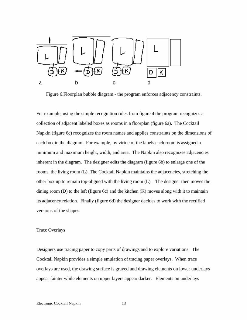
Figure 6.Floorplan bubble diagram - the program enforces adjacency constraints.
For example, using the simple recognition rules from figure 4 the program recognizes a
collection of adjacent labeled boxes as rooms in a floorplan (figure 6a). The Cocktail
Napkin (figure 6c) recognizes the room names and applies constraints on the dimensions of
each box in the diagram. For example, by virtue of the labels each room is assigned a
minimum and maximum height, width, and area. The Napkin also recognizes adjacencies
inherent in the diagram. The designer edits the diagram (figure 6b) to enlarge one of the
rooms, the living room (L). The Cocktail Napkin maintains the adjacencies, stretching the
other box up to remain top-aligned with the living room (L). The designer then moves the
dining room (D) to the left (figure 6c) and the kitchen (K) moves along with it to maintain
its adjacency relation. Finally (figure 6d) the designer decides to work with the rectified
versions of the shapes.
Trace Overlays
Designers use tracing paper to copy parts of drawings and to explore variations. The
Cocktail Napkin provides a simple emulation of tracing paper overlays. When trace
overlays are used, the drawing surface is grayed and drawing elements on lower underlays
appear fainter while elements on upper layers appear darker. Elements on underlays

Electronic Cocktail Napkin 14
cannot be erased or edited, but the designer can select elements on lower trace layers and
copy them to the top layer.
Trace tabs at the top left of the drawing area (see figure 5) enable the designer to select a
particular layer. After selecting a trace tab, the designer can shift the entire trace layer or
remove it from the drawing and put it aside for later consideration. Trace layers removed
from the drawing appear as icons in a scrapbook area along the top of the window.
Drawings in the scrapbook can later be reinserted as trace layers, or copied onto the top
drawing layer.
Collaborative Drawing
Drawing is seldom a solo, often a social, act. The diagram is a medium in a conversation,
or an argument, about design. Therefore, it is important that the electronic version allow at
least two designers to work together sharing the drawing surface. Two experimental
versions were built. In the first version (figure 7 a), two tablets are connected to two serial
i/o ports of the same computer; in the second version (figure 7 b) designers share a single
tablet. (For the single tablet version, the designers use pens with different electronic
signatures. In one experiment we modified Wacom's pen hardware; in another we used
two different off the shelf components: a pressure and a standard stylus.) In both versions
designers share a single drawing work area on the screen and their respective marks appear
in two different colors. The two tablet version is a prototype for two designers working
together over a network. The single tablet version represents the more familiar situation of
designers working together in the same place.

Electronic Cocktail Napkin 15
Figure 7. a - Two designers share a tablet; b - each designer has a tablet.
In both the one and the two tablet version, the Cocktail Napkin stores the author's identity
with each drawn glyph and the designers can replay construction of the drawing step by
step. This simple approximation of a design history can reveal how a diagram was made,
and it provides design researchers a way to study drawing protocols. To enhance the
design history, we use the computer's audio input capability to record the designers'
conversation as the diagram is made, tagging each drawing element with a pointer into the
sound track file. Thus the conversation can be replayed along with the drawing. A
designer can point to a drawing element and hear the related conversation fragment, that is,
what was said when the element was drawn. This feature could be used to record rationale
during designing and later store it more formally, for example in an issue based information
system such as McCall's PHIDIAS program (McCall and Johnson 1994).
4. Diagram based query & retrieval
Two small prototypes were built that illustrate how diagrams might be used to index
databases of architectural information. In the first prototype, the Cocktail Napkin is used
to query a visual database of images of famous buildings (Gross 1994). In the second, the
Cocktail Napkin is used to index post-occupancy evaluations of libraries and courthouses.
Both schemes explore how design information databases can be integrated into a drawing

Electronic Cocktail Napkin 16
environment, enabling designers to obtain task-relevant information in a more natural way
than keyword queries.
Image retrieval by diagram
The first prototype finds images in a small database of ten famous buildings, It was built
with the assistance of an undergraduate student, Kristin Mayfield Anderson. We first
asked 20 architects, design instructors, and students to make diagrams of the buildings
from memory. Perhaps because designers know these buildings well, the diagrams they
made were quite consistent. For example, diagrams of Wright's Guggenheim museum fell
into three main classes: 3 or 4 stacked boxes, a 2-dimensional spiral, and a corkscrew
representation of a helix (figure 8).
STACKEDBOXES
STACKEDBOXES(cont’d)
SPIRAL
CORKSCREW
Figure 8. Designer's diagrams of Wright's Guggenheim museum (from memory).
Electronic Cocktail Napkin 17
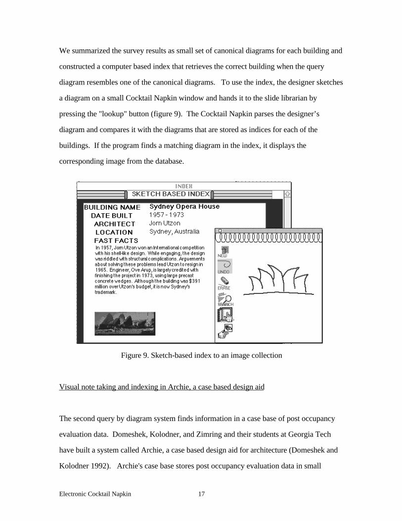
We summarized the survey results as small set of canonical diagrams for each building and
constructed a computer based index that retrieves the correct building when the query
diagram resembles one of the canonical diagrams. To use the index, the designer sketches
a diagram on a small Cocktail Napkin window and hands it to the slide librarian by
pressing the "lookup" button (figure 9). The Cocktail Napkin parses the designer’s
diagram and compares it with the diagrams that are stored as indices for each of the
buildings. If the program finds a matching diagram in the index, it displays the
corresponding image from the database.
Figure 9. Sketch-based index to an image collection
Visual note taking and indexing in Archie, a case based design aid
The second query by diagram system finds information in a case base of post occupancy
evaluation data. Domeshek, Kolodner, and Zimring and their students at Georgia Tech
have built a system called Archie, a case based design aid for architecture (Domeshek and
Kolodner 1992). Archie's case base stores post occupancy evaluation data in small
Electronic Cocktail Napkin 18
chunks of text and graphics classified as stories, problems, and responses. The case data
are linked by related concepts -- for example, the designer can browse from one lighting
problem to the next. The data are also indexed by features expressed as key words. For
example, the designer can use the feature index to search Archie’s cases for stories about
circulation systems and ambient noise.
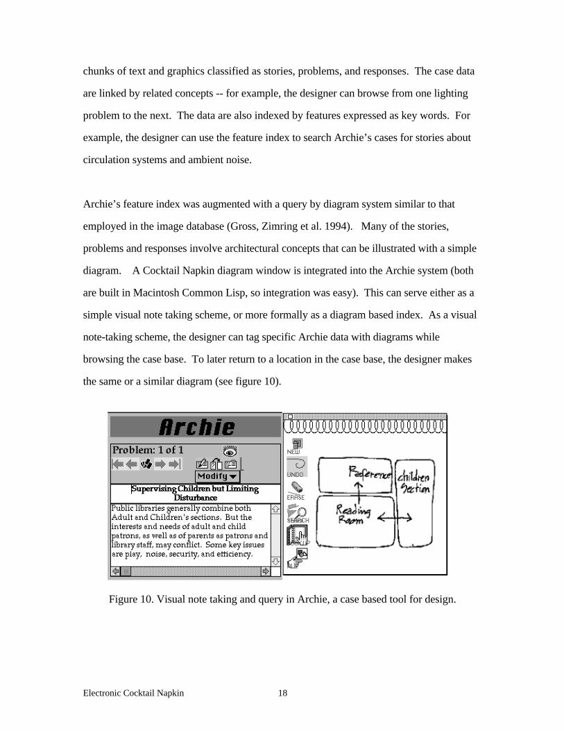
Archie’s feature index was augmented with a query by diagram system similar to that
employed in the image database (Gross, Zimring et al. 1994). Many of the stories,
problems and responses involve architectural concepts that can be illustrated with a simple
diagram. A Cocktail Napkin diagram window is integrated into the Archie system (both
are built in Macintosh Common Lisp, so integration was easy). This can serve either as a
simple visual note taking scheme, or more formally as a diagram based index. As a visual
note-taking scheme, the designer can tag specific Archie data with diagrams while
browsing the case base. To later return to a location in the case base, the designer makes
the same or a similar diagram (see figure 10).
Figure 10. Visual note taking and query in Archie, a case based tool for design.

Electronic Cocktail Napkin 19
We used this scheme to construct a small diagram index into the Archie case base. We
made diagrams of the entries to be indexed, using mostly bubble diagrams, lines and
arrows, text labels, and a few special symbols.
5. Related work
The Electronic Cocktail Napkin project lies at the intersection of several areas of research:
artificial intelligence and cognitive science, visual computing languages and human
computer interaction, and design and CAD.
Workers in artificial intelligence and cognitive science are studying the use of visual
representations in reasoning. There is ample evidence that people find diagrams and
drawings extremely helpful in understanding problems. In his book on method, "How to
solve it," mathematician George Polya exhorts, "draw a figure!" Physicist Richard
Feynman invented a system of diagrams to think more easily about the behavior of atomic
particles. In a landmark paper, "Why a diagram is (sometimes) worth 10,000 words,"
(Larkin and Simon 1987), Larkin and Simon argue that features of visual representations,
for example spatial grouping of diagram elements, implicitly provides information and can
support certain inferences. A recent symposium on visual representations and reasoning
brought together AI researchers working in this area (Chandrasekaran, Narayanan et al.
1993).
Several studies have looked at the role of drawing in design cognition. Goldschmidt has
looked at alternation and linking of visual and verbal thinking in design using protocol
studies of designers at work (Goldschmidt 1991). Goel, challenging a widely accepted
computational model of mind that depends on well-structured problem representations,
argues that designers use ill-structured representations to match the ill-structured nature of
Electronic Cocktail Napkin 20
design problems (Goel 1992). Schön (Schön 1992) viewed the drawing as an external
medium that can "talk back to" the designer. Much work has appeared recently on the
process and media of drawing and its role in design, focusing for example, on engineering
design (Ullman, Wood et al. 1989; Ferguson 1992), architectural study drawings (Herbert
1993) categories of drawings and their uses (Herbert 1993), and the sociology of design
drawing (Robbins 1994). In the realm of art, Fish and Scrivener argue that artists sketch
both to clarify existing ideas and to develop new ones (Fish and Scrivener 1990).
In the visual computing languages community, work has proceeded in two areas directly
related to the Cocktail Napkin project: recognition and parsing of visual language and
schemes for query by diagram. Lakin (Lakin, Wambaugh et al. 1989) along the lines
followed here articulates the need for incremental formalization in design, and proposes an
approach to parsing visual expressions. Parsing visual language is a central topic in the
visual language community (Golin 1991), (Marriott 1994) (Wittenburg and Weitzman
1990) but typically for more formally structured visual expressions than one finds in
working diagrams. Kimura and others have built pen-based drawing environments that
include facilities for recognition, parsing, and editing (Kimura, Sengupta et al. 1994).
However, these environments do not aim to support design. Visual query schemes for
databases has been an active, if offbeat, area of research and lately there has been a surge of
interest in this area. Although much work on query by diagram deals with diagrams of non
visual data (e.g. entity-relationship diagrams used to construct database queries), at least
some work deals with diagram query for visual data (Kato, Kurita et al. 1991; Tabuchi,
Yagawa et al. 1991; DelBimbo, Campanai et al. 1992).
Curiously, in computer aided design, work on diagrams and hand drawn representations
has been scant. In the early 1970's, Negroponte's Architecture Machine Group at MIT
worked on recognizing and interpreting hand drawn sketches (Negroponte 1973), but they

Electronic Cocktail Napkin 21
abandoned this line of research in the mid '70's. Some of that work -- on latching,
straightening, and curve drawing -- has become standard in computer graphics, but other
problems identified in sketch recognition -- recognizing floor plans, interpreting three-
dimensional sketches -- remain largely unresolved twenty years later.
Little work in CAD has been done on generating diagrams; even less on parsing and
interpreting them. Ervin wrote a program that produces diagrams given a textual
description of design elements and relations (Ervin 1990) and another diagram layout tool
was built by Dave (Dave 1993). Foundational work has been done on requirements for
computer supported sketching (Kolli and Hennessey 1993), but little has been published on
sketch recognition and diagram interpretation. The most active area of research in pen-
based interfaces has been collaborative work and shared drawing spaces (Bly 1988; Ishii
and Miyake 1991; Minneman and Bly 1991; Harrison 1993). However, this work
concentrates on the mechanics of shared editing and is not concerned with interpreting
drawings or more generally, with design.
6. Discussion and Further Work
Summary
The Electronic Cocktail Napkin is a prototype diagramming environment for conceptual
designing based on the premise that tools for early stage designing must not demand great
effort, commitment, or precision. The Cocktail Napkin's pen-based interface enables a
designer to directly make and work with drawings that can be ambiguous and imprecise.
Yet eventually the crude diagram must be made more precise, committed and detailed.
Therefore the computer must provide a means to identify design elements and relations and

Electronic Cocktail Napkin 22
to edit the diagram in light of this information. Although initially the Cocktail Napkin does
not structure or even necessarily recognize diagram elements, the designer can make the
initial diagrams into more structured drawings in a process of incremental formalization.
The Cocktail Napkin has three major components: facilities for recognition and parsing,
constraint management routines, and more general support for drawing management.
To support the gradual transition from diagram to schematic drawing, the Cocktail Napkin
provides facilities for recognition and parsing . Both the low level recognizer for glyphs
and the higher-level recognizer for configurations can be trained or programmed
interactively by the designer. The parsing mechanisms can also be employed to search a
sketchbook or other database for similar diagrams. The scheme of recognition by a series
of graphical replacement rules recalls the shape grammars of Stiny, Mitchell, and others.
However, the Cocktail Napkin's replacement rules are used to parse diagrams, rather than
to generate them, and parsing is carried out from the bottom up.
Many elements and relations carry over from low-commitment diagrams to more structured
schematic drawings. The Cocktail Napkin's constraint management routines can maintain
and enforce these relations, providing the schematic drawing with interactive edit behavior
inferred from the diagram. For example, after recognizing a floor plan bubble diagram, the
Cocktail Napkin can apply size constraints to rooms and relative position constraints
between them. In addition to recognizing elements and relations, and maintaining
constraints among diagram elements, computer based drawing environments should also
support simple but valuable features of paper. Therefore the Cocktail Napkin also provides
trace overlays, supports multiple users and can replay a drawing history, and can search
and manage a sketchbook of previously made drawings.

Electronic Cocktail Napkin 23
Future Work
Further work would develop the Cocktail Napkin beyond the prototype stage so that it
could be employed in real design settings and tested by real designers. The goal of the
Cocktail Napkin project is to bring the power of computing to early stage design, before
key decisions have been made, and when feedback from critiques and simulation, and
access to design information can have the greatest impact on the design. Important
decisions are made in the early stages that affect a design's performance. Most
computational support for editing, critiquing, simulation, and analysis requires a design to
be represented in a highly structured format, e.g. a STEP or DXF model. Therefore
feedback from knowledge based tools is unavailable until the design can be represented in a
more structured fashion. Providing computational representations for early stage design
suggest how these tools might be employed sooner rather than later.
The two experiments in query by diagram illustrate how one might connect or embed a
designing environment with databases of design information, such as an image collection
or a case based design aid. It is unclear how these pilot experiments will scale up; we plan
to expand the size of the databases to explore scaling strategies. In future, we plan to link
the Cocktail Napkin environment with other knowledge rich tools like Archie, such as the
critics and design rationale database in PHIDIAS and Janus (McCall and Johnson 1994).
Another avenue of exploration would extend the Cocktail Napkin program to support less
directly symbolic forms of drawing, for example sketches, that are nevertheless important
precursors to formal and structured design representations. The Cocktail Napkin project
has focused on diagrams, sketches are arguably different in their character and role in
design. Sketches are less directly symbolic than diagrams, and more focused on shape
properties. For example, the Cocktail Napkin reads and stores pressure data from the pen
but this information, though meaningful, remains unused. We plan to add support for both
Electronic Cocktail Napkin 24
the lower level graphical acts of sketching such as overtracing and bearing down as well as
the higher level intentions of representing shape, texture, and other relevant architectural
information. Finally, we plan to add simple interpretation of three-dimensional sketches
(thumbnail isometric diagrams, for example) using standard computer vision algorithms.
Acknowledgements
Kristin Mayfield Anderson, an undergraduate at Colorado built and debugged the sketch
based slide index. Ellen Do, a PhD student at Georgia Tech worked on the diagram index
to Archie and contributed valuable ideas throughout. Discussions with Aaron Fleisher,
Kyle Kuczun, Ray McCall, and Craig Zimring were illuminating. The support of grant
#DMI 93-13186 from the National Science Foundation is gratefully acknowledged.
References
Bly, S. (1988). A Use of Drawing Surfaces in Different Collaborative Settings.
Conference on Computer-Supported Cooperative Work, Portland, Oregon, ACM.
Chandrasekaran, B., N. H. Narayanan, et al. (1993). “Reasoning with Diagrammatic
Representations.” AI Magazine 14(2): 49-56.
Dave, B. (1993). CDT: A Computer Assisted Diagramming Tool. CAAD Futures ‘93 -
Proceedings of the Fifth International Conference on Computer-Aided Architectural Design
Futures. Amsterdam, North-Holland. 91-109.
DelBimbo, A., M. Campanai, et al. (1992). Using 3D Spatial Relationships for Image
Retrieval. IEEE Workshop on Visual Languages, Seattle, WA, IEEE. 184-190.
Electronic Cocktail Napkin 25
Domeshek, E. and J. Kolodner (1992). A case-based design aid for architecture. Artificial
Intelligence in Design. J.S. Gero (ed) Netherlands, Kluwer.
Ervin, S. M. (1990). Designing with Diagrams. The Electronic Design Studio:
Architectural Knowledge and Media in the Computer Age. Cambridge, MA, MIT Press.
107-122.
Ferguson, E. (1992). Engineering and the Mind’s Eye. Cambridge, MA, MIT Press.
Fish, J. and S. Scrivener (1990). “Amplifying the Mind’s Eye: Sketching and Visual
Cognition.” Leonardo 23(1): 117-126.
Goel, V. (1992). “Ill-structured representations” for ill-structured problems. Fourteenth
Annual Conference of the Cognitive Science Society, Bloomington, IN, Hillsdale, NJ:
Erlbaum. 844-849.
Goldschmidt, G. (1991). “The dialectics of sketching.” Creativity Research Journal 4(2):
122-143.
Golin, E. (1991). A Method for the Specification and Parsing of Visual Languages. PhD
dissertation. Brown University.
Gross, M. (1990). Relational Modeling. The Electronic Design Studio. Cambridge, MA,
MIT Press. 123-136.
Gross, M. D. (1992). Graphical Constraints in CoDraw. IEEE Workshop on Visual
Languages, Seattle, IEEE Press. 81-87.
Electronic Cocktail Napkin 26
Gross, M. D. (forthcoming). Indexing visual databases of designs with diagrams, in
Visual Databases in Architecture, Koutamanis, Timmermans, & Vermeulen, (ed) Avebury
Press.
Gross, M. D., C. Zimring, et al. (1994). Using Diagrams to Access a Case Base of
Architectural Designs. in Artificial Intelligence in Design ‘94. J.S. Gero (ed) Lausanne,
Kluwer.
Harrison, S. (1993). “Computing and the Social Nature of Design.” ACADIA Quarterly
12(1): 10-18.
Herbert, D. (1993). Architectural Study Drawings. New York, Van Nostrand Reinhold.
Ishii, H. and N. Miyake (1991). “Toward an Open Shared Workspace: Computer and
Video Fusion Approach of Team Workstation.” Communications of the ACM 34(12): 37-
50.
Kato, T., T. Kurita, et al. (1991). A Cognitive Approach to Visual Interaction.
International Conference on Multimedia Information Systems, Singapore,
Kimura, T. D., S. Sengupta, et al. (1994). “A Graphic Diagram Editor for Pen
Computers.” Software - Concepts and Tools (82-95): 82-95.
Kolli, R. and J. Hennessey (1993). Deriving the Functional Requirements for a Concept
Sketching Device: A Case Study. Human Computer Interaction: Vienna Conference
VCHCI ‘93, Fin de Siècle. Springer-Verlag. 184-195.

Electronic Cocktail Napkin 27
Lakin, F., J. Wambaugh, et al. (1989). “The electronic notebook: performing medium and
processing medium.” Visual Computer 5: 214-226.
Larkin, J. and H. Simon (1987). “Why a diagram is (sometimes) worth 10,000 words.”
Cognitive Science 11: 65-99.
Marriott, K. (1994). Constraint Multiset Grammars. IEEE Symposium on Visual
Languages, St. Louis, IEEE. 118-125.
McCall, R., P. Bennett, and E. Johnson (1994). An overview of the Phidias II
HyperCAD System, Proceedings of ACADIA (Association for Computer Aided Design in
Architecture), St Louis, MO. 63-77.
Minneman, S. L. and S. A. Bly (1991). Managing à trois: a study of a multi-user drawing
tool in distributed design work. Conference on Human Factors in Computing Systems
(CHI ‘91), New Orleans, LA, ACM Press / Addison Wesley.
Mitchell, W. J. (1990). Logic of Architecture. Cambridge, MA, MIT Press.
Negroponte, N. (1973). Recent advances in sketch recognition. AFIPS (American
Federation of Information Processing) National Computer Conference, Boston, MA.
Robbins, E. (1994). Why Architects Draw. Cambridge, MA, MIT Press.
Schön, D. (1992). “Designing as Reflective Conversation with the Materials of a Design
Situation.” Knowledge Based Systems 5(3)
Electronic Cocktail Napkin 28
Stiny, G. (1980). “Introduction to Shape and Shape Grammars.” Environment and
Planning B 7: 343-351.
Sutherland, I. (1963). Sketchpad - a Graphical Man-Machine Interface. PhD dissertation,
M.I.T.
Tabuchi, M., Y. Yagawa, et al. (1991). Hyperbook: A Multimedia Information System that
Permits Incomplete Queries. Proc. of International Conference on Multimedia Information
Systems, Singapore.
Ullman, D., S. Wood, et al. (1989). The Importance of Drawing in the Mechanical Design
Process. NSF Engineering Design Research Conference, Amherst MA.
Wittenburg, K. and L. Weitzman (1990). Visual Grammars and Incremental Parsing. IEEE
Workshop on Visual Languages, Skokie, IL, IEEE Press.
Woodbury, R., A. Radford, et al. (1992). Tartan Worlds: A Generative Symbol Grammar
System. ACADIA ‘92, Charleston SC, ACADIA.


![Napkin Rings2[2]](https://img.dokumen.tips/doc/110x75/5571faae497959916992d3ca/napkin-rings22.jpg)


