Embed Size (px)
Citation preview

1
The effects of shear on delamination in layered materials
S. Li1, J. Wang1 and M. D. Thouless1,2
1Department of Mechanical Engineering2Department of Materials Science & Engineering
University of MichiganAnn Arbor, MI 48109, U.S.A.
Keywords: adhesion and adhesive (A), delamination (A), energy-release rate (A),
fracture (A), elastic material (B)
Abstract
The effect of transverse shear on delamination in layered, isotropic, linear-
elastic materials has been determined. In contrast to the effects of an axial load
or a bending moment on the energy-release rate for delamination, the effects of
shear depend on the details of the deformation in the crack-tip region. It
therefore does not appear to be possible to deduce rigorous expressions for the
shear component of the energy-release rate based on steady-state energy
arguments or on any type of modified beam theory. The expressions for the
shear component of the energy-release rate presented in this work have been
obtained using finite-element approaches. By combining these results with
earlier expressions for the bending-moment and axial-force components of the
energy-release rates, the framework for analyzing delamination in this type of
geometry has been extended to the completely general case of any arbitrary
loading. The relationship between the effects of shear and other fracture
phenomena such as crack-tip rotations, elastic foundations and cohesive zones
are discussed in the final sections of this paper.
(March 2003)

2
1. Introduction
Linear-elastic fracture mechanics expressions for the delamination of
layered materials subjected to bending and axial loading (Fig. 1) were derived by
Suo and Hutchinson (Suo and Hutchinson, 1990; Hutchinson and Suo, 1992).
The magnitude of the energy-release rate, GM, and the complex stress-intensity
factor, KM, associated with a bending moment, M, are given by (Suo and
Hutchinson, 1990)
E f H Mh KM M M1 13 2 21 1G = ( ) = −( ) −( )−α β α, // (1a)
where E E= −( )/ 1 2ν in plane strain or E E= in plane stress, E is Young’s
modulus, ν is Poisson’s ratio, and the subscripts 1 and 2 denote arms 1 and 2
(Fig. 1). The first Dundurs parameter, α, is given by α = (Σ-1)/(Σ+1), where
Σ = E E1 2/ . The second Dundurs parameter, β, is given by
βν ν
= ( ) − ( )+
ΣΣ
f f2 1
1
and f ν ν( ) = −12
in plane stress
or f ν νν
( ) = −−( )
1 22 1
in plane strain.
h is the depth of the arms, H = h1/h2, and the constant fM(α, H) is given by
f H HM α αα
,/
( ) = + +−
6 111
3
1 2
. (1b)
The magnitude of the energy-release rate, GP, and the complex stress-intensity
factor, KP, associated with an axial load, P, (when the bending moment, M, is
equal to zero) is given by (Suo and Hutchinson, 1990)

3
E f H Ph KP P P1 1
1 2 21 1G = ( ) = −( ) −( )−α β α, // (2a)
where,
f H H H HP α αα
, . ./
( ) = + +−
+ +( )
0 511
1 5 3 23 21 2
. (2b)
Energy-release rates for arbitrary combinations of bending moments and
axial loads can be determined by adding the individual components of the stress-
intensity factors in a vectorial fashion, provided the appropriate phase angles for
pure bending, ψM, and axial loading, ψP, are known (Fig. 2). These phase angles
are generally defined so that they are zero when the imaginary part of the
quantity Khi1ε is zero (Suo and Hutchinson, 1990), where
επ
ββ
= −+
12
11
ln , (3)
From Fig. 2 it can be seen that the energy-release rate for combined loading is
given by
G G G G G= + + ( )P M P M PM21 2/
cosγ , (4a)
or,
E f H
Ph
f HMh
f H f HPMhP M P M PM1
22
1
22
13
122G = ( ) + ( ) + ( ) ( )α α α α γ, , , , cos , (4b)
where fM(α, Η) and fP(α, Η) are given by Eqn. (1) and (2), and
γPM = ψ ψP M−
= cos, ,
− +( )−( ) ( ) ( )
121
13α
α α αH
f H f HM P
. (5)
If the phase angle for one of the two loading conditions is known, the other can
be immediately calculated from Eqn. 5. The two phase angles are functions of α,
4
β and H. They were calculated by Suo and Hutchinson (1990), and the full
results can be found in that reference. Examples of ψM(α, 0, H) for the special
case of β = 0 are reproduced in Table 11, since they are used in the present paper.
These results of Suo and Hutchinson (1990) allow the interfacial fracture
mechanics of any general bi-layer geometry to be calculated when only bending
moments and axial loads act at the crack tip. However, in general, there will be a
transverse shear force, V, at the crack tip in addition to a bending moment and
an axial force (Fig. 3). The contribution of this transverse shear force to the
energy-release rate needs to be incorporated in a full analysis of the interfacial
fracture mechanics of bi-layers. One well-known example where this transverse
shear force is significant is the double-cantilever beam (D.C.B.) geometry in
which the moment is supplied to the crack tip by the action of a remote load.
Indeed, it has been noted by a large number of authors that there is an additional
contribution to the energy-release rate (Gillis and Gilman, 1964,; Mostovoy et al.,
1967; Wiederhorn et al., 1968; Kanninen, 1973, 1974; Suo et al., 1991; Bao et al.,
1992; Sun and Pandey, 1994; Williams, 1987, 1989, 1995), or to the stress-intensity
factor (Fichter, 1983), beyond that expected only from pure bending. Previous
explanations for this correction have included both the effects of shear, and
“root-rotation” or other manifestations of elastic deformation ahead of the crack
tip. It will be shown in this paper that while the correction can be completely
and accurately accounted for in terms of the shear component of the energy-
1 The values presented in Table 1 have been recalculated by the present authors using finite-element techniques. These represent some additional values of H, and some of the values appearto be slightly more accurate than the original values given in Suo and Hutchinson (1990).

5
release rate, crack-tip deformation does affects this component in a way that it
does not affect the other two components.
The major thrust of this paper is to determine the effects of transverse
shear on the energy-release rate and phase angle for delamination. When
combined with the results of Suo and Hutchinson (1990), this analysis completes
the general solution for plane, linear-elastic, interfacial fracture mechanics of
layered materials. By incorporating crack-tip shear, bending and axial loading,
these results can be used to calculate energy-release rates and phase angles for
any beam-like geometry subjected to arbitrary loading. As particular examples,
it is shown that this approach provides complete descriptions for the mechanics
of various double-cantilever beam geometries that are in excellent agreement
with finite-element calculations. Furthermore, the results also allow an
understanding to be developed for the relative roles of shear, cohesive zones,
root-rotation, and elastic foundations on the fracture behavior of layered
materials.
2. Calculations and results
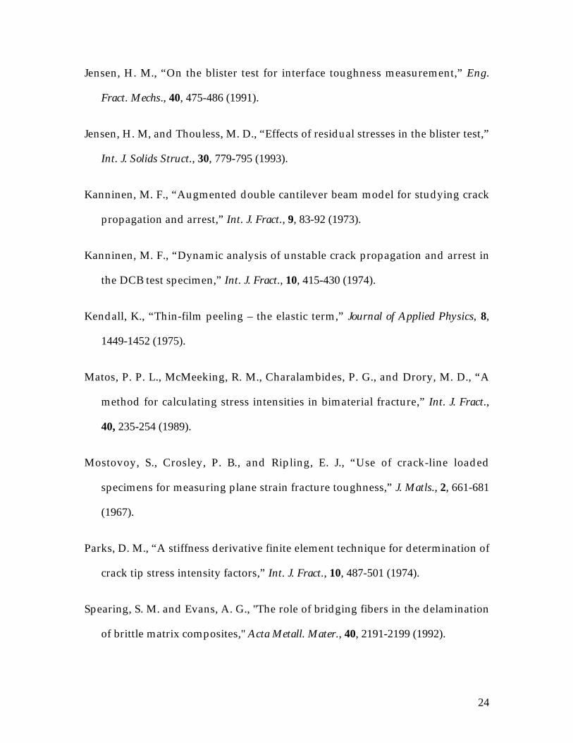
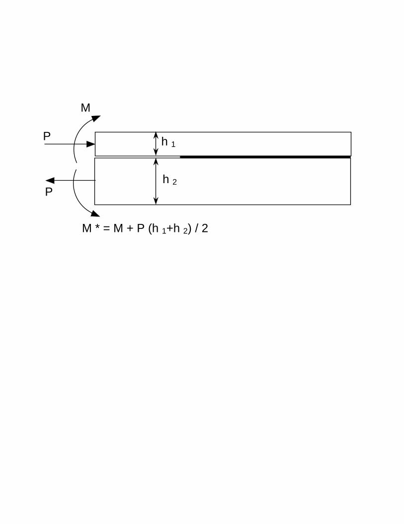
The energy-release rate associated with a moment, M, at the crack tip can
be computed from a geometry in which the arms are subjected to a pure bending
moment (Fig. 1), while the energy-release rate associated with an axial load, P, at
the crack tip can be computed from a geometry in which the arms are subjected
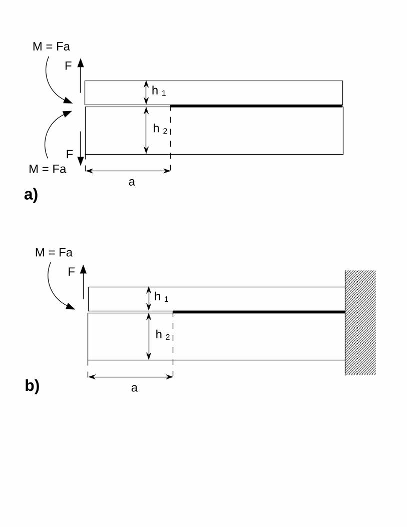
to a uniform load plus the required compensating moment (Fig. 1). The effect of
a transverse shear force, V , acting at the crack tip can be determined by
examining a geometry in which the moment at the crack tip resulting from an
applied shear force is exactly cancelled by a pure moment of equal and opposite

6
magnitude (Fig. 4a). It should be noted that while a crack parallel to the axis of a
beam does not affect the stress distribution caused by an axial load or a bending
moment (Suo and Hutchinson, 1990), it does affect the stress distribution caused
by a shear force. Therefore, for completeness, the results presented in this paper
include the effects of a single transverse shear force acting on only one arm
(Fig. 4b), in addition to the effects of equal forces acting on both arms (Fig. 4a).
The analysis was performed numerically using the ABAQUS (version 5.8)
finite-element code. The crack tip was surrounded by a square mesh of 30 rings
each of which contained 160 eight-noded, isoparametric, plain-strain elements.
The two modes of energy-release rate were determined using the virtual-crack
extension method (Parks, 1974; Haber and Koh, 1985; Matos et al., 1989). To
ensure an acceptable level of accuracy, the mesh sensitivity and effects of remote
boundary conditions were explored, and estimates of the levels of uncertainty
are included in the tables of results presented in this paper. The shear forces
were applied as point loads at the centroidal axes of the beams.
A series of systematic, parametric calculations showed that, provided the
crack is long enough, the phase angles and energy-release rates are independent
of the crack length, a. Generally, these crack-length independent results are
realized when the distance to the end of either beam is greater than its thickness.
The magnitudes of the energy-release rates, GV and GV1, and the complex stress-
intensity factors, KV and KV1, associated with pure shear forces acting at the crack
tip are given by
E f H Vh KV V V1 11 2 21 1G = ( ) = −( ) −( )−α β β α, , // , (6a)

7
for a double-shear force (Fig. 4a), and
E f H Vh KV V V1 1
1 2 21 1 1
1 1G = ( ) = −( ) −( )−α β β α, , // , (6b)
for a single shear force (Fig. 4b). The phase angles are of the form ψ α βV H, ,( )
and ψ α βV H1
, ,( )._ While these equations are very similar in form to Eqns. 1 and 2,
analytical results do not exist for fV(α, β, H) and f HV1α β, ,( ) ; they have to be
found numerically. These numerical solutions indicate that the second Dundurs
parameter, β, not only affects the phase angle, but also has a very small influence
on the magnitude of the energy-release rate. This is in contrast to the solutions
for an axial load or bending moment where β affects only the phase angle. Sets
of values for fV(α, 0, H), f HV1α β, ,( ) , ψV(α, 0, H), and ψ α βV H
1, ,( ) are given in
Tables 2 and 3 for a full range of H, and for different values of the modulus
mismatch (with β = 0).
3. Discussion
3.1 General beam-like geometries
The energy-release rate and phase angle for a layered material subjected
to an arbitrary combination of axial load, P, transverse load, V and bending
moment, M at the crack tip (Fig. 3) can now be calculated. The energy-release
rate is given by
E f HPh
f H
f HMPh
f H
f HVP
f HMh
f
PM
PPM
V
PPV
MV
12
2
1 1
22
13
1 2 2
1
G = ( ) + ( )( )
+ ( )
( )
+ ( ) +
ααα
γαα
γ
αα β
,,
,cos
,
,cos
,, ,,
,
, ,
,cos
H
f HVhM
f H
f HVhMM
V
MMV
( )( )
+ ( )( )
α
α βα
γ2
1
2
12
(7)

8
where, γ ψ α β ψ α βPM P MH H= ( ) − ( ), , , ,
γ ψ α β ψ α βPV P VH H= ( ) − ( ), , , ,
γ ψ α β ψ α βMV M VH H= ( ) − ( ), , , , .
The phase angle is given by
ψα ψ α ψ α β ψα ψ α ψ α β ψ
=( ) + ( ){ } + ( ){ }( ) + ( ){ } + ( ){ }
−tan, sin , / sin , , / sin
, cos , / cos , , / cos1 1 1
1 1
f H f H Ph M f H Vh M
f H f H Ph M f H Vh MM M P P V V
M M P P V V
(8)
As an example, consider a double-cantilever beam with a crack length a that is
loaded remotely by applied loads, F. The crack tip is subjected to transverse
shear forces, V = F, bending moments, M = Fa, and no axial loads. Therefore, the
energy-release rate can be obtained from Eqn. 7:
E f HFa
h
f H
f Hha
f H
f HhaM
V
M
V
MMV1
2
2
13
2
1
2
110
20
G = ( ) ( ) + ( )( )
+ ( )( )
α
αα
αα
γ,, ,
,
, ,
,cos , (9)
and the phase angle can be obtained from Eqn. 8:
ψα ψ α ψα ψ α ψ
={ } ( ) + ( ){ } ( ) + ( )
−tan
/ , sin , , sin
/ , cos , , cos1 1
1
0
0
a h f H f H
a h f H f HM M V V
M M V V
, (10)
where fM(α, H) is given by Eqn. 1(b), and ψ M (α, 0, H), fV(α, 0, H) and
ψV(α, 0, H) are given in Tables 1 and 2. In particular, if α = 0 and the geometry is
symmetrical so that H = 1 and ψ Μ = ψV = γM V = 0, then fM(0, 1) = 12 and
fV(0, 0, 1) = 2.335. Equation (9) then reduces to the simple form of
G =12
1 0 6742
3
2Fa
Eh
h
a( ) +
. . (11)
Apart from a minor correction in the third significant figure, this is
indistinguishable from the empirical fit to finite-element calculations given by
9
Bao et al. (1992).2 Further examples of comparisons between Eqns. 9 and 10 and
the results of finite-element calculations for different values of α and H are given
in Figs. 5 and 6. It will be seen that the concept of separating the energy-release
rate into a moment component and a shear component provides an excellent
method of analyzing these geometries. In particular, these results now allow the
effect of modulus mismatch on the phase angle and energy-release rate to be
determined for asymmetrical double-cantilever beams.
The concept of splitting the applied loads into a moment, an axial force
and a shear force acting at the crack tip can be applied to many other geometries,
even those exhibiting non-linear deformations.3 For example, consider a
symmetrical double-cantilever beam (D.C.B.) undergoing large-scale
deformations, so that the lever arm between the applied load and the crack tip
gets smaller as deformation proceeds. Eventually, the geometry changes from a
D.C.B. configuration to a symmetrical 90º T-peel configuration. Therefore, the
energy-release rate must vary between one limit given by Eqn. 11 that is valid for
small deformations, and a second limit given by the T-peel result (Kendall, 1975)
of G / / /Eh P Eh P Eh= ( ) +( )1 that is valid for large deformations (provided the
strains remain linear). Using a non-linear finite-element analysis to compute the
lever arm and, hence, the crack-tip bending moment, Eqn. 9 was used to
2 It should be noted that the ASTM standard (D3433-93) for tests using double-cantilever beams
is based on the equation G = +4 32 2 2 3F a h Eh( ) / , which comes from an approximate analyticalresult for the effects of shear as described by Mostovoy et al. (1967). This equation has anincorrect crack-length dependence and gives an error in G that can be as large as 52% for a/h = 1.The error is still as large as 12% for a/h = 10. These errors are only slightly less than thoseassociated with not correcting for shear at all.3 It should be noted that warping of the beam occurs owing to the shear force and to the non-uniformity of the stresses at the crack tip region. This limits the accuracy of the analytical

10
calculate the energy-release rate. Finite-element methods were also used to
calculate a numerical value for the energy-release rate. The excellent agreement
between these two sets of results, and the transition between the two limiting
solutions can be seen in Fig. 7. A final comment on calculating energy-release
rates for geometries undergoing large deformations or rotations by means of the
approach presented in this paper is to note that if the geometry of interest
includes a crack-tip region that is subjected to a rigid-body rotation (such as
would occur in a bending beam), and the direction of the applied load is fixed,
care has to be taken to resolve the applied load into the appropriate shear and
axial components acting at the crack tip before using Eqns. 7 and 8.
3.2 Comment on analytical approaches
The results of Eqns. 1 and 2 for the bending-moment and axial-load
components of the energy-release rate can readily be obtained from simple beam
theory. The similarity in form between these two equations and Eqn. 6 may
suggest the possibility of developing a similar approach for the shear component
using higher-order beam theories that incorporate shear. Unfortunately, this
does not seem to be possible. A hint of the problem is provided by comparing
the details of Eqns. 1(a) and 1(b), which can be obtained by beam theory, to
Eqn. 6, which that cannot. The numerical constants in the first two equations
depend only on the geometry and one Dundurs parameter, α. The numerical
constant in Eqn. 6 has an additional dependence on the second Dundurs
parameter, β. This difference indicates that while the bending-moment and
axial-load components of the energy-release rate are unaffected by details of the
approach to problems involving relatively small strains (although large deformations can be

11
deformation in the crack tip region, the shear component is fundamentally
affected by this local deformation.
The fact that the bending-moment and axial-load components of the
energy-release rate are unaffected by details of the deformation in the crack-tip
region manifests itself by the existence of solutions that can be obtained by
steady-state energy-balance arguments. A similar steady-state argument cannot
be developed for shear because a state of uniform shear cannot act over the
length of a beam in the absence of an associated gradient in bending moment.
Therefore, while Eqn. 6 correctly implies that a crack tip can be acted on by pure
shear (any bending moment component from the applied shear load being
eliminated by the application of an equal and opposite pure bending moment), it
would be misleading to consider this equation to be a steady-state solution in the
same way that Eqn. 2(a) can be considered to be a steady-state solution for
loading by a pure bending moment. It can readily be shown that a steady-state
energy balance based only on the parabolic shear-stress distribution that exists
well away from the crack tip and the point of load application does not result in
the correct result for the shear component of the energy-release rate. This is
because such an approach neglects the contribution of the crack tip deformation
on the energy-release rate.
The deformation in the crack-tip region has been described in terms of
“root-rotation” effects, where planes rotate in response to the applied loading
(Williams, 1987; 1989), and “elastic-foundation” effects, where there are strains
perpendicular to the crack plane (Kanninen, 1973, 1974). These effects are
accommodated).

12
discussed in more detail in subsequent sections. This deformation in the crack-
tip region occurs to various degrees when any shear force, bending moment or
axial load is applied to a beam-like geometry. However, it only affects the shear
component of the energy-release rate. When calculating the moment and axial-
load components of the energy-release rate, it doesn’t matter what assumption is
made about the boundary conditions where the beam is attached to the substrate
at the crack tip; any assumption results in rigorously correct solutions because
the crack-tip deformation doesn’t contribute to the solution. Conversely, since
the crack tip region does affect the shear component of the energy-release rate,
the results of beam-based analyses are dependent on the nature of the
assumptions made about the boundary conditions at the crack tip. Rigorous
solutions for the shear component of the energy-release rate can only be obtained
by an analysis of the full elastic problem including a correct description of the
interface between the two arms. This is the analysis that has been performed in
the present paper by means of a finite-element method.
3.3 Root rotations
Consider a section just behind the crack tip that is initially normal to the
centroidal axis of an arm in a beam-like geometry. After loading, this section
may rotate as shown in Fig. 8. Two types of rotation can occur. The angle
between the section and the centroidal axis can change – this is the shear strain at
the crack tip. The other type of rotation occurs when the centroidal axis and the
section rotate together – this is “root rotation.” In general, the magnitude of root
rotation will not be uniform across the section, but the average value is

13
considered to be the “root rotation angle” in this paper. If the crack length is
long enough to avoid boundary effects, the root rotation angle is given by
θo M P VcM
E hc
P
E hc
V
E h= + +
1 12
1 1 1 1
, (12)
where cM, cP, cV are functions of the elastic constants and geometry. The first two
coefficients, cM and cP, appear to be functions of α and β, whereas cV appears to be
a function of all three non-dimensional elastic constants. Values for all three
coefficients are given in Fig. 9 as a function of α (with β = 0).4
Root rotation is sometimes invoked as a reason for the difference between
the expressions for the energy-release rate of a layered material loaded by a
moment and the same geometry loaded by an applied force. However, it can be
seen from Eqn. 12 that root rotation is a very general effect, and is not associated
just with the application of a shear force. Furthermore, the general expressions
of Eqns. 1, 2 and 7 for the components of the energy-release rate are always valid
and completely incorporate any possible effects of root rotation. Therefore, root
rotation should not be considered as an independent contributor to the energy-
release rate. Energy-release rates can be calculated with reference only to the
crack-tip axial load, moment and shear force; root rotation does not provide an
independent contribution. However, root rotation can play a very important role
in the fracture mechanics of beam-like geometries if it causes a large enough
change in geometry to affect significantly the calculation of the crack-tip forces
and moments for a particular geometry. For example, the original calculations
(Hutchinson and Suo, 1992) for the energy-release rate of buckling-driven

14
delaminations under compressively-stressed thin films were based on the
assumption of “clamped boundary conditions.” It was assumed that the critical
stress required to buckle a film with a given size of delamination is identical to
that of a plate of the same size, but clamped around the perimeter. The energy-
release rate was then calculated from Eqns. 1 and 2 by determining the bending
moment and axial force that act at the clamped boundaries of a buckled plate. A
clamped boundary is tantamount to assuming no root rotation at the crack tip.
However, as shown by Cotterell and Chen (2000), and Yu and Hutchinson (2002),
this assumption of a clamped boundary (no root rotation) may cause significant
errors in calculating the crack-tip moment and force if the substrate is compliant.
Under these conditions, accurate calculations of the moment and force need to
incorporate the root rotation. Once these have been calculated, Eqns. 1 and 2
then provide rigorous solutions for the energy-release rate.
Shear does not contribute to the energy-release rate in these buckling-
driven delamination problems. However, it does contribute to other significant
thin-film geometries such as the blister test and the peel test. Existing analyses of
the blister test are based on the assumption of a clamped boundary at the crack
tip, and they neglect the effects of shear (Jensen, 1991; Jensen and Thouless,
1993). While the energy-release rate for an elastic peel test can be obtained
directly from a steady-state energy-balance argument (Kendall, 1975), existing
calculations of the phase angle also ignore the effects of shear (Thouless and
Jensen, 1992). Shear effects in a peel test exhibiting plastic deformation have
4 Note that in the results presented in Fig. 9, the root rotation is defined as the average rotation ofthe plane at the crack tip. This is a different definition from that used by Yu and Hutchinson(2002) and is responsible for the slight discrepancy between the two sets of results.

15
been identified (Yang et al., 2001), as have shear effects in wedge tests with
plastic deformation (Yang et al., 1999).
3.4 Cohesive zones
Cohesive zones and elastic foundations are two inter-related concepts that
also appear in the literature in connection with the effects of shear. The final two
sections of the discussion will attempt to clarify the role of these two phenomena
in the elastic fracture mechanics of layered materials. The discussion so far has
been limited to problems with uniform linear-elastic constitutive properties
throughout both portions of a bi-material beam. If the cohesive tractions at the
interface contribute negligibly to the overall compliance of the system, this
discussion is valid, and linear-elastic fracture mechanics is appropriate.
However, additional complications arise if the cohesive tractions between the
two materials contribute significantly to the compliance of the system.
It has been demonstrated (Tvergaard and Hutchinson, 1992) that there are
two important cohesive parameters that dominate mode-I fracture: the cohesive
strength, )σ , and the toughness, Γ Io. Details of the shape of the traction-
separation law for the cohesive tractions have a minor influence on the
mechanics. Using a cohesive-zone model described elsewhere (with a
trapezoidal traction-separation law) (Yang et al., 1999; Cavalli and Thouless,
2001), the effects of these two dominant parameters can be explored using a
symmetrical, linear-elastic, double-cantilever beam as a model. The resultant
load-displacement curves are shown in Fig. 10, and compared to the results of
linear-elastic calculations. These curves show that if E hIoΓ /)σ 2 is less than about
0.4, the cohesive strength has a negligible effect on the deformation and fracture

16
of the beam, and the toughness is the only interfacial parameter that affects
fracture. The linear-elastic result of Eqn. 11, which incorporates shear, then
provides an accurate description of the fracture mechanics, and the interfacial
toughness can be obtained from a double-cantilever geometry by substituting the
maximum load obtained experimentally into Eqn. 11 and equating the energy-
release rate to the toughness.5 The toughness of the interface is then the only
interfacial parameter that affects fracture. If E hIoΓ /)σ 2 is greater than about 0.4,
the peak load is significantly reduced from what would be predicted by L.E.F.M.,
and this approach would not be valid. Both the strength and compliance of the
joint would then be required to find the fracture parameters (Suo et al., 1992;
Spearing and Evans, 1992).
Inspection of Fig. 10 suggests a simple, elegant and very practical way of
deducing the interfacial toughness from a double-cantilever beam experiment
when E hIoΓ /)σ 2 is unknown. It will be noted that the cohesive zone is fully
developed at the peak load and, subsequently, the crack grows maintaining a
cohesive zone of constant size ahead of its tip. In this regime the load-
displacement plot does not depend on the cohesive strength. In other words, the
LEFM results provide a master curve for crack propagation. (The results for
different cohesive strengths are simply translated to different effective crack
lengths.) It can be shown that this master curve relating the cracking load, Fc, to
the crack-mouth opening displacement, δ, is given by
5 It is noted that the standard formulation for the validity of linear-elastic fracture mechanics
(L.E.F.M.) is that h Kc Y> ( )2 52
. /σ , where σY is the yield strength, and Kc is the fracture toughness
of the interface. Recognizing that K Ec Io= Γ , it can be seen that this standard formulation is
17
F
Eh Eh hc Io
=
−2 3 2 11
3 3Γ / δ
. (13)
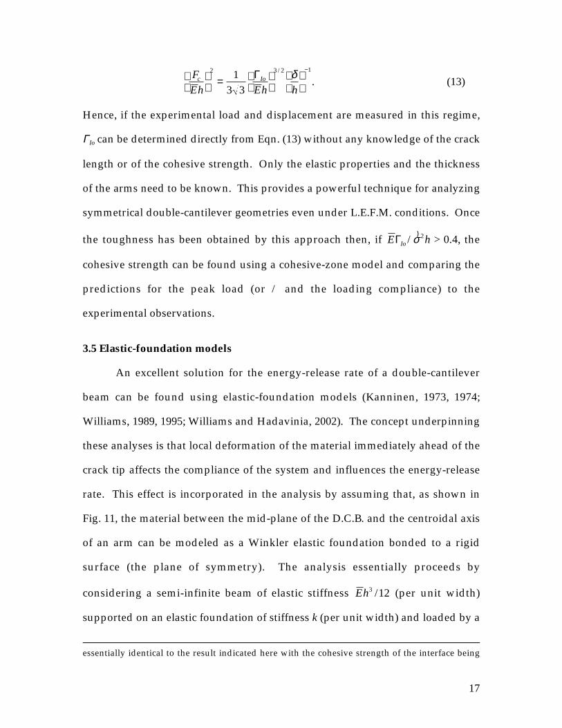
Hence, if the experimental load and displacement are measured in this regime,
ΓIo can be determined directly from Eqn. (13) without any knowledge of the crack
length or of the cohesive strength. Only the elastic properties and the thickness
of the arms need to be known. This provides a powerful technique for analyzing
symmetrical double-cantilever geometries even under L.E.F.M. conditions. Once
the toughness has been obtained by this approach then, if E hIoΓ /)σ 2 > 0.4, the
cohesive strength can be found using a cohesive-zone model and comparing the
predictions for the peak load (or / and the loading compliance) to the
experimental observations.
3.5 Elastic-foundation models
An excellent solution for the energy-release rate of a double-cantilever
beam can be found using elastic-foundation models (Kanninen, 1973, 1974;
Williams, 1989, 1995; Williams and Hadavinia, 2002). The concept underpinning
these analyses is that local deformation of the material immediately ahead of the
crack tip affects the compliance of the system and influences the energy-release
rate. This effect is incorporated in the analysis by assuming that, as shown in
Fig. 11, the material between the mid-plane of the D.C.B. and the centroidal axis
of an arm can be modeled as a Winkler elastic foundation bonded to a rigid
surface (the plane of symmetry). The analysis essentially proceeds by
considering a semi-infinite beam of elastic stiffness Eh3 12/ (per unit width)
supported on an elastic foundation of stiffness k (per unit width) and loaded by a
essentially identical to the result indicated here with the cohesive strength of the interface being

18
moment M (per unit width) and a shear force V (per unit width) at one end. The
displacement at the edge of the elastic foundation is given by (Barber, 2001)
uk
Vk
Mo = +2 2 2λ λ , (14)
where λ = ( )3 3 1 4k Eh/
/. Recognizing that there two halves to this mode-I
geometry, the energy-release rate for the crack can be written as
G = kuo2 . (15)
Hence, from Eqn. 14 it can be seen that
EE
hk
V
h
M
hG = 2 632 12
1 4
1 2 3 2
2
./
/ /
+
. (16)
It is noted that the stiffness of the foundation has no effect on the moment
component of the energy-release rate, and Eqn. 16 reduces to Eqn. 1 for H = 1 and
α = 0 if there is no shear force. However, the shear component of the energy-
release rate is sensitive to assumptions about the stiffness of the foundation. This
further emphasizes the point made in Section 3.2 that, while the moment
component of the energy-release rate does not depend on the deformation in the
crack-tip region, the shear component does.
A physical argument was made in Kanninen (1973) that k ≈ 2 E /h. This
results in a very good agreement with numerical results for the double-cantilever
beam. However, it is interesting to note that if one chooses k = 1.615 E /h, Eqn. 16
becomes
E Vh MhG = 2 335 121 2 3 2 2. / /− −+[ ] , (17)
represented by the yield stress.
19
which is identical to Eqn. 11. This exact match to the rigorous solution for the
shear component of the energy-release rate only works for the perfectly
symmetrical case when the phase angle is zero. However, the approach (with
the same value for k) can be used to obtain an approximate analytical result for
fv(α, 0, H). If the analysis is repeated for a asymmetrical double-cantilever beam
(assuming again that the foundation can be split into two portions corresponding
to each arm), the following result is obtained:
f H Hv ( , , ) .α α α0 1 65 1 1 11
≈ + +( ) −( )−. (18)
It will be observed from Table 2(a) that this result generally provides quite a
good fit to the values given in Table 2(a). An elastic foundation approach can
also be used to provide a good approximation to the solution for the energy-
release rate associated with a combined shear and bending moment (Williams,
1995). While this approach can correctly reproduce the first two terms of Eqn. 9,
it does not accurately describe the interaction between the two components (the
last term in Eqn. 9); nor does it provide any information about the phase angle.
An approximate analytical result for a cohesive zone in a double-
cantilever beam geometry can be developed using the elastic-foundation model.
It should be noted that the springs for such a model need to include two
elements in series. The first element represents the deformation of the arms, and
can be modeled by springs that have a spring constant of kd = 1.615 E /h. The
second element represents the cohesive zone. As noted by Williams and
Hadavinia (2002), analytical models can be developed for cohesive-zone
elements with different types of constitutive properties. Here, the cohesive zone
is represented by linear-elastic elements, so that the spring constant is given by

20
kc Io= )σ 2 / Γ (19)
(since there are two halves to the D.C.B. geometry). The effective spring constant
is then given by
kk k
k k
E h
E hd c
d c
Io
Io
=+
=( )
+ ( )1 615
1 1 615
2
2 2
. /
. /
ΓΓ
)
)σσ
, (20)
and, from Eqn. 16, the expression for the energy-release rate of a point-loaded
double-cantilever beam with a crack of length a becomes
G = + +
121 0 674 1 1 62
2 2
3 2
1 4 2
F a
Eh
h
a
E
hIo. .
/Γ)σ
. (21)
An expression for the load at which crack growth occurs, Fc, is then given by
equating G to ΓIo:
F
Eh Eh
a
h
E
hc Io Io=
+ +
−Γ Γ
120 674 1 1 62
1 2
2
1 4 1/ /
. . )σ(22)
This result is in moderately good agreement with the predicted fracture loads
shown in the numerical data of Fig. 10. However, there is some discrepancy
associated with the different choices of the cohesive law used in the two
calculations.6
4. Conclusions
The forces and moments acting on the tip of a crack in a layered material
under any general plane loading can be described in terms of an axial
compressive load, a bending moment and a transverse shear load. It is possible
to express the energy-release rate and the phase angle in terms of three separate

21
components associated with each of the three types of loading. In this paper, the
results for the shear component have been presented. In contrast to the results
for the moment and axial-force components, the shear component of the energy-
release rate cannot be derived from either a steady-state energy argument or
from a beam analysis (even a higher-order theory that incorporates shear). This
is because the details of the crack-tip deformation play a crucial role in the case
of shear. The effect of shear is not merely a second-order correction to a simple
Euler-Bernoulli beam-theory approach to the mechanics of layered materials.
Shear loading at the crack tip is an important and independent phenomenon that
completes the triad of possible crack-tip loading configurations for a layered
material. For example, in a short double-cantilever beam, the shear component
can contribute as much as two thirds of the total energy-release rate. It is
theoretically possible for the shear component to be even more dominant if, for
example, a gradient of internal residual stresses in a thin film counteracts any
moment associated with an applied load (as in Fig. 4).
The results presented in this paper for the shear component of the energy-
release rate can be combined with the results previously derived by Suo and
Hutchinson (1990) for the axial-load and bending-moment components to
analyze any general loading of layered materials and other beam-like geometries.
For example, it is possible to use Eqns. 10 and 11 to calculate the energy-release
rate and phase angle of any double-cantilever beam geometry with a modulus
mismatch and different thicknesses of arms. It has been shown that predictions
6 The nature of the relationship between the fracture load and the cohesive strength (Eqn. 22)indicates how estimates of Fc for given values of
)σ are not be very sensitive to the assumedcohesive law, but estimates of
)σ obtained from observations of Fc are much more sensitive.

22
from this type of analysis provide excellent agreement with numerical
calculations. A particular illustration of this analysis is the fracture mechanics of
a symmetrical double-cantilever beam. It has been shown that the analysis
results in the commonly accepted equation for the energy-release rate of a D.C.B.
that includes a “correction factor” to the equation that is derived from
considerations of pure bending. This “correction factor” arises from the shear
component to the energy-release rate, it does not arise from factors such as root
rotation, cohesive zones or elastic foundations. The significance of these
phenomena and models in the mechanics of layered materials have been
discussed in the last section of this paper.
Acknowledgements
This work was partially supported by NSF Grant No. CMS9624452, and
by the Department of Mechanical Engineering, University of Michigan.

23
References
ASTM D3433-93 “Standard test method for fracture strength in cleavage of
adhesives in bonded joints,” American Society for Testing and Materials (1993).
Bao, G., Ho, S., Suo Z., and Fan, B., “The role of material orthotropy in fracture
specimens for composites,” Int. J. Solids Structures, 29, 1105-1116 (1992).
Barber, J. R., chapter 7 in Intermediate Mechanics of Materials, McGraw Hill, NY,
(2001).
Cavalli, M. N., and Thouless, M. D., “The effect of damage nucleation on the
toughness of an adhesive joint,” J. Adhesion, 76, 75-92 (2001).
Cotterell B., and Chen, Z., “Buckling and cracking of thin films on compliant
substrate under compression,” Int. J. Fract., 104, 169-179 (2000).
Fichter, W.B., “Stress intensity factor for the double cantilever beam,” Int. J.
Fract., 22, 133-143 (1983).
Gillis, P. P., and Gilman, J. J., “Double-cantilever cleavage mode of crack
propagation,” J. Appl. Phys., 35, 647-658 (1964).
Haber, R. B., and Koh, H. M., “Explicit expressions for energy release rates using
virtual crack extensions,” Int. J. For Numerical Methods in Engineering, 21, 301-
315 (1985).
Hutchinson, J. W., and Suo, Z., “Mixed-mode cracking in layered materials,”
Advances in Applied Mechanics, 29, 64-187 (1992).
24
Jensen, H. M., “On the blister test for interface toughness measurement,” Eng.
Fract. Mechs., 40, 475-486 (1991).
Jensen, H. M, and Thouless, M. D., “Effects of residual stresses in the blister test,”
Int. J. Solids Struct., 30, 779-795 (1993).
Kanninen, M. F., “Augmented double cantilever beam model for studying crack
propagation and arrest,” Int. J. Fract., 9, 83-92 (1973).
Kanninen, M. F., “Dynamic analysis of unstable crack propagation and arrest in
the DCB test specimen,” Int. J. Fract., 10, 415-430 (1974).
Kendall, K., “Thin-film peeling – the elastic term,” Journal of Applied Physics, 8,
1449-1452 (1975).
Matos, P. P. L., McMeeking, R. M., Charalambides, P. G., and Drory, M. D., “A
method for calculating stress intensities in bimaterial fracture,” Int. J. Fract.,
40, 235-254 (1989).
Mostovoy, S., Crosley, P. B., and Ripling, E. J., “Use of crack-line loaded
specimens for measuring plane strain fracture toughness,” J. Matls., 2, 661-681
(1967).
Parks, D. M., “A stiffness derivative finite element technique for determination of
crack tip stress intensity factors,” Int. J. Fract., 10, 487-501 (1974).
Spearing, S. M. and Evans, A. G., "The role of bridging fibers in the delamination
of brittle matrix composites," Acta Metall. Mater., 40, 2191-2199 (1992).

25
Sun, C. T., and Pandey, R. K., “Improved method for calculating strain energy
release rate based on beam theory,” AIAA Journal, 32, 184-189 (1994).
Suo, Z., and Hutchinson, J. W., “Interface crack between two elastic layers.,” Int.
J. Fract., 43, 1-18 (1990).
Suo, Z., Bao, G., Fan, B., and Wang, T. C., “Orthotropy rescaling and implications
for fracture in composites,” Int. J. Solids and Structures, 28, 235-248 (1991).
Suo, Z., Bao, G., and Fan, B., “Delamination R-curve phenomena due to
damage,” J. Mech. Phys. Solids, 40, 1-16 (1992).
Thouless, M. D., and Jensen, H. M., “Elastic fracture mechanics of the peel-test
geometry,” J. Adhesion, 38, 185-197 (1992).
Tvergaard, V., and Hutchinson, J. W., “The relationship between crack growth
resistance and fracture process parameters in elastic plastic solids,” J. Mech.
and Phys. Solids, 40, 1377-1397 (1992).
Wiederhorn, S. M., Shorb, A. M. and Moses, R. L., “Critical analysis of the theory
of the double cantilever method of measuring fracture-surface energies,” J.
Applied Phys., 39, 1569-1572 (1968).
Williams, J. G., “Large displacement and end block effects in the ‘DCB’
interlaminar test in modes I and II,” Journal of Composite Materials, 21, 330-347
(1987).
Williams, J. G., “End corrections for orthotropic DCB specimens,” Composites
Science and Technology, 35, 367-376 (1989).

26
Williams, J. G., “Fracture in adhesive joints-the beam on elastic foundation
model” Proceedings of ASME International Mechanical Congress & Expositions,
1112-1117 (1995).
Williams, J. G., and Hadavinia, H., “Analytical solutions for cohesive zone
models,” J. Mechs. Phys. Solids, 809-825 (2002).
Yang, Q. D., Thouless, M. D., and Ward, S. M. “Analysis of the symmetrical 900-
peel test with extensive plastic deformation,” J. Adhesion, 72, 115-132 (2000).
Yang, Q. D, Thouless, M. D., and Ward, S. M., “Numerical Simulations of
Adhesively-Bonded Beams Failing with Extensive Plastic Deformation,” J.
Mech. Phys. Solids, 47, 1337-1353 (1999).
Yu, H. H. and Hutchinson, J. W., “Influence of substrate compliance on buckling
delamination of thin films,” Int. J. Fract., 113, 39-55 (2002).

27
Table 1 The phase angle, ψ α βM H, ,( ), for delamination of a bilayer subjected
to a pure bending moment and β = 0. The uncertainty of these
results is better than ± 0.1°.
αααα -0.8 -0.6 -0.4 -0.2 0 0.2 0.4 0.6 0.8H0.0 -43.3° -42.3° -41.0° -39.6° -37.9° -35.9° -33.4° -30.1° -24.9°
0.2 -43.0° -41.3° -39.4° -37.3° -34.8° -31.8° -28.1° -22.9° -14.3°
0.4 -41.5° -38.4° -35.1° -31.6° -27.5° -22.8° -16.9° -8.9° +4.0°
0.6 -39.2° -34.1° -29.1° -23.8° -18.1° -11.8° -4.3° +5.2° +18.5°
0.8 -36.0° -28.8° -22.1° -15.4° -8.6° -1.3° +6.6° +15.8° +27.3°
1.0 -32.4° -23.0° -14.9° -7.3° 0.0° +7.3° +14.9° +23.0° +32.4°

28
Table 2(a) The coefficient f HV α β, ,( ) for delamination of a bilayer subjected to a
double transverse shear loads and β = 0. The uncertainties are ± 0.007
for H ≥ 0.2.
αααα -0.8 -0.6 -0.4 -0.2 0 0.2 0.4 0.6 0.8H0.0 see Table 3(a)
0.2 1.635 1.687 1.753 1.833 1.940 2.089 2.300 2.654 3.412
0.4 1.645 1.708 1.784 1.881 2.009 2.186 2.439 2.865 3.800
0.6 1.663 1.739 1.836 1.954 2.106 2.314 2.619 3.125 4.250
0.8 1.684 1.781 1.898 2.037 2.217 2.460 2.809 3.394 4.704
1.0 1.711 1.829 1.968 2.127 2.335 2.605 3.003 3.665 5.127
Table 2(b) The phase angle, ψ α βV H, ,( ) , for delamination of a bilayer subjected
to double transverse shear loads and β = 0 . The uncertainties are
± 0.2° for H ≥ 0.2.
αααα -0.8 -0.6 -0.4 -0.2 0 0.2 0.4 0.6 0.8H0.0 see Table 3(b)
0.2 +4.6° +3.4° +2.1° +0.7° -0.6° -2.1° -3.6° -5.1° -6.6°
0.4 +4.5° +3.3° +1.9° +0.6° -0.8° -2.1° -3.5° -4.8° -5.9°
0.6 +4.5° +3.3° +2.1° +0.8° -0.5° -1.8° -3.1° -4.3° -5.3°
0.8 +4.7° +3.5° +2.3° +1.0° -0.3° -1.5° -2.7° -3.9° -5.0°
1.0 +4.8° +3.7° +2.5° +1.3° 0.0° -1.3° -2.4° -3.6° -4.9°

29
Table 3(a) The coefficient f HV1α β, ,( ) (with β = 0) for delamination of a bilayer
subjected to a single transverse shear load on the arm 1. The
uncertainties are ± 0.007 for H ≥ 0.2 and ± 0.03 for H = 0.
αααα -0.8 -0.6 -0.4 -0.2 0 0.2 0.4 0.6 0.8H0.0 1.64 1.69 1.76 1.84 1.94 2.09 2.29 2.61 3.28
0.2 1.607 1.628 1.662 1.715 1.791 1.902 2.075 2.380 3.055
0.4 1.531 1.507 1.510 1.545 1.618 1.729 1.908 2.214 2.851
0.6 1.413 1.354 1.351 1.386 1.458 1.573 1.746 2.023 2.518
0.8 1.282 1.206 1.206 1.247 1.323 1.434 1.590 1.812 2.137
1.0 1.150 1.077 1.088 1.133 1.207 1.306 1.438 1.607 1.787
Table 3(b) The phase angle, ψ α βV H1
, ,( ) (with β = 0) for delamination of a
bilayer subjected to single transverse shear load on arm 1. The
uncertainties are ± 0.1° for H ≥ 0.2 and ± 0.5° for H =0.
αααα -0.8 -0.6 -0.4 -0.2 0 0.2 0.4 0.6 0.8H0.0 +5.0° +4.0° +3.0° +2.0° +0.7° -0.5° -1.7° -3.1° -4.8°
0.2 +4.3° +2.6° +0.8° -1.2° -3.5° -6.0° -8.7° -11.7° -15.1°
0.4 +3.2° +0.6° -2.0° -4.6° -7.4° -10.0° -12.6° -15.2° -17.9°
0.6 +1.6° -1.9° -4.9° -7.6° -10.5° -12.8° -15.0° -17.1° -19.1°
0.8 -0.5° -4.6° -7.7° -10.2° -13.0° -14.9° -16.7° -18.3° -19.8°
1.0 -3.0° -7.5° -10.5° -12.7° -15.1° -16.3° -17.7° -19.0° -20.2°

30
Figure captions
Figure 1 The general beam-like geometry subjected to axial loads and
bending moments for which the interfacial fracture mechanics have
been determined by Suo and Hutchinson (1990).
Figure 2 A schematic illustration of vectorial addition of stress-intensity
factors (and square roots of energy-release rates).
Figure 3 The general geometry of a layered material subjected to axial loads,
bending moments and transverse shear loads.
Figure 4 (a) A beam-like geometry subjected to double transverse shear
loads and double opposing bending moments. (b) A beam-like
geometry subjected to a single transverse shear load and an
opposing bending moment.
Figure 5 Comparison between the analytical results (curves) and finite-
element results (data points) for a double-cantilever beam with
H = 1 and different values of α. Plots are shown for (a) non-
dimensional energy-release rate, and (b) phase angle.
Figure 6 Comparison between the analytical results (curves) and finite-
element results (data points) for a thin film (H = 0) loaded by a
transverse shear force on a thick substrate, for different values of α.
Plots are shown for (a) the non-dimensional energy-release rate,
and (b) the phase angle.
Figure 7 A comparison of the energy-release rate for a symmetrical double-
cantilever beam undergoing large-scale deformation calculated

31
from finite-element results (closed circle) and from the analytical
approach presented in this paper (closed diamond). The bending
moments used in the analytical results were calculated from the
deformations predicted by finite-element calculations.
Figure 8 Root rotation and shear on a section at the crack tip.
Figure 9 Plots of the coefficients for the root rotation angle as a function of α
for H = 1 (open symbols) and H= 0 (closed symbols), and for β = 0.
Figure 10 A plot of the load versus displacement for a symmetrical double-
cantilever beam calculated using a cohesive-zone model, for an
initial crack length ao = 2h.
Figure 11 An elastic foundation model for a double-cantilever beam used to
analyze the effects of deformation between the centroidal axis of
the arms and the mid-plane of the geometry, as proposed by
Kanninen (1973, 1974).
h 1
h 2P
P
M
M * = M + P (h 1+h 2) / 2

ψP
ψM
ψPM
Imaginary component of complexstress intensity factor = 0
Rea
l com
pone
nt o
f com
plex
str
ess
inte
nsity
fact
or =
0
K EM M=
−( )−( )
1
1 2 1
αβ
G
K EP P=
−( )−( )
1
1 2 1
αβ
G K E=
−( )−( )
1
1 2 1
αβ
G

h 1
h 2P
P
M
M * = M + P (h 1+h 2) / 2
V
V
a)
h 1
h 2
M = Fa
F
F
aM = Fa
h 1
h 2
M = Fa
F
ab)

0
20
40
60
80
100
0 5 10 15 20 25 30
α = 0.8
α = 0.0
α = -0.8
Nom
aliz
ed e
nerg
y-re
leas
e ra
te,
Normalized crack length, a / h1
Gh 13 a
2/
E1
h 1
F
h 2 = h 1F
a

-40
-30
-20
-10
0
10
20
30
40
0 5 10 15 20 25 30
Pha
se a
ngle
, ψ
(de
gree
s)
Normalized crack length, a / h1
α = -0.8
α = 0.0
α = 0.8
h 1
F
h 2 = h 1
Fa

0
2
4
6
8
10
12
14
16
18
0 5 10 15 20 25 30
Normalized crack length, a / h1
Nom
aliz
ed e
nerg
y-re
leas
e ra
te,
Gh 13 a
2/
E1
α = 0.0
α = 0.8
α = -0.8
h 1
F
1 /h 2 = 0a

-45
-40
-35
-30
-25
-20
-15
-10
-5
0 5 10 15 20 25 30
Pha
se a
ngle
, ψ
(de
gree
s)
Normalized crack length, a / h1
α = 0.8
α = 0.0
α = -0.8
h 1F
h 1 /h 2 = 0a

0
1
2
3
4
5
6
7
0 1 2 3
Nor
mal
ized
ene
rgy-
rele
ase
rate
, G
/ Eh
(10-3
)
Normalized load, (10-3)F / Eh
1 0.9 0.8 0.7 0.65
T-peel asymptote
DCB asymptote
Normalized crack length, ( )a/ao
ao / h = 10
ao
a
F
F
h
h

θo + shear strainθo

0
5
10
15
20
-1 -0.5 0 0.5 1
Coe
ffici
ent
for
root
rot
atio
n ( β
= 0
)
α
cM
c'V
cP
H = 0
H = 1
θ = cM M/Eh
1 2 + c
P P/Eh
1 + (c'
V-ν
1 )V/Eh
1

/ ΓIo
= 1000Eh
ao h/ = 2
0 1 2
Nor
mal
ized
loa
d,
F /
Eh
Normalized crack mouth opening displacement, δ / h
E ΓIo
/ σ 2h^ = 0.1
E ΓIo
/ σ 2h^ = 0.5
E ΓIo
/ σ 2h^ = 10
E ΓIo
/ σ 2h^ = 50
LEFM result
0.002
0.001
0.003
0.004
0
h
F
h F
ao

M
M
V
V
h
h
A B
C D
M
VC D
A B


![Numerical Example - Contact Study A two layered [0 0 /90 0 ] laminate with a pre-existing delamination at the ply interface is considered. The plate is](https://img.dokumen.tips/doc/110x75/551813da550346a2318b458a/numerical-example-contact-study-a-two-layered-0-0-90-0-laminate-with-a-pre-existing-delamination-at-the-ply-interface-is-considered-the-plate-is.jpg)


![The effects of shear on Mode II delamination: a critical review · 2018. 12. 12. · delamination length according to the Irwin–Kies formula [72]: 2 2 PdC G Bda (2) Depending on](https://img.dokumen.tips/doc/110x75/61201f051f393242aa74bcab/the-effects-of-shear-on-mode-ii-delamination-a-critical-review-2018-12-12.jpg)