Embed Size (px)
Citation preview
‘The effects of hydrogen injection in natural gas networks for the Dutch underground storages’
Final ReportCommissioned by the ministry of Economic Affairs

I 5
Contents
List of tables ............................................................................................................................ IV
List of abbreviations and formulas ......................................................................................... V
Management Summary ....................................................................................................... 1
Introduction ......................................................................................................................... 4
Underground gas storages in the Netherlands ................................................................. 6
3.1 General remarks ........................................................................................................... 6
3.2 Subsurface ................................................................................................................... 7
3.3 Pore reservoirs ........................................................................................................... 13
General remarks ............................................................................................... 13
Grijpskerk .......................................................................................................... 13
Norg (Langelo) .................................................................................................. 15
Bergermeer ....................................................................................................... 17
Alkmaar ............................................................................................................. 19
3.4 Salt caverns ............................................................................................................... 21
Zuidwending & Heiligerlee – Winschoten .......................................................... 21
General description of potential effects and damages in UGS facilities caused by
hydrogen ............................................................................................................................ 23
4.1 General remarks ......................................................................................................... 23
4.2 Tightness and hydraulic integrity of the cap rock ........................................................ 23
4.3 Geochemical reactions ............................................................................................... 24
4.4 Changes in transport mechanisms in the reservoir ..................................................... 25
4.5 Microbiological reactions ............................................................................................ 25
4.6 Technical integrity / reliability of material .................................................................... 26
Introduction ....................................................................................................... 26
Integrity of steel alloys ....................................................................................... 27
Integrity of cementation in UGS wells ................................................................ 28
Integrity of elastomers and seals ....................................................................... 28
4.7 Operational effects ..................................................................................................... 29
4.8 Experience with town gas storage in Europe .............................................................. 29
Hydrogen content up to 0.5 % .......................................................................................... 31
5.1 General remarks ......................................................................................................... 31
5.2 Tightness and hydraulic integrity of the cap rock ........................................................ 31
Clay ................................................................................................................... 31
Faults ................................................................................................................ 32
Salt .................................................................................................................... 33
5.3 Geochemical reactions ............................................................................................... 34
Dissolution......................................................................................................... 34

II 5
Changes of the reservoir brine due to dissolution .............................................. 35
Hydrogen impact on dissolved ions ................................................................... 36
Dissolution and precipitation of reservoir rocks .................................................. 37
5.4 Changes in transport mechanisms in the reservoir ..................................................... 37
5.5 Microbiological reactions ............................................................................................ 37
5.6 Technical integrity/reliability of materials..................................................................... 39
Integrity of steel alloys ....................................................................................... 39
Integrity of cementation of UGS wells ................................................................ 40
Integrity of elastomers and seals ....................................................................... 40
Implications for safety measures based on Netherlands state of the art well
completion ......................................................................................................... 40
5.7 Additional considerations upon salt caverns ............................................................... 40
Hydrogen content up to 10 % ........................................................................................... 41
6.1 General remarks ......................................................................................................... 41
6.2 Tightness and hydraulic integrity ................................................................................ 41
Clay ................................................................................................................... 41
Faults ................................................................................................................ 41
Salt .................................................................................................................... 41
6.3 Geochemical reactions ............................................................................................... 41
Dissolution......................................................................................................... 41
Changes of the reservoir brine due to dissolution .............................................. 42
Hydrogen impact on dissolved ions ................................................................... 42
Dissolution and precipitation of reservoir rocks .................................................. 43
6.4 Changes in transport mechanisms in the reservoir ..................................................... 43
6.5 Microbiological reactions ............................................................................................ 44
6.6 Technical integrity/reliability of materials..................................................................... 45
Integrity of steel alloys ....................................................................................... 45
Integrity of cementation of UGS wells ................................................................ 45
Integrity of elastomers and seals ....................................................................... 45
Implication for safety measures based on Netherlands state of the art well
completion ......................................................................................................... 45
6.7 Additional considerations upon salt caverns ............................................................... 45
Hydrogen content up to 100 % ......................................................................................... 46
7.1 General remarks ......................................................................................................... 46
7.2 Tightness and hydraulic integrity ................................................................................ 46
Clay ................................................................................................................... 46
Faults ................................................................................................................ 46
Salt .................................................................................................................... 46
7.3 Geochemical reactions ............................................................................................... 47
Dissolution......................................................................................................... 47
III 5
Changes of the reservoir brine due to dissolution .............................................. 47
Hydrogen impact on dissolved ions ................................................................... 47
Dissolution and precipitation of reservoir rocks .................................................. 47
7.4 Changes in transport mechanisms in the reservoir ..................................................... 47
7.5 Microbiological reactions ............................................................................................ 47
7.6 Technical integrity / reliability of materials ................................................................... 47
Integrity of steel alloys ....................................................................................... 47
Integrity of cementation of UGS wells ................................................................ 47
Integrity of elastomers and seals ....................................................................... 48
Implication for safety measures based on Netherlands state of the art well
completion ......................................................................................................... 48
7.7 Additional considerations upon salt caverns ............................................................... 48
Hydrogen Injection into the natural gas network in neighbouring countries ............... 51
8.1 General remarks ......................................................................................................... 51
8.2 Hydrogen injection into the natural gas grid ................................................................ 52
Denmark ........................................................................................................... 53
Germany ........................................................................................................... 53
Belgium ............................................................................................................. 55
United Kingdom ................................................................................................. 55
8.3 Underground gas storage strategies in neighbouring countries .................................. 55
8.4 Safety regulations for hydrogen injection .................................................................... 59
International and European standards or rules .................................................. 60
Denmark ........................................................................................................... 62
Germany ........................................................................................................... 62
Belgium ............................................................................................................. 63
United Kingdom ................................................................................................. 63
Summary ............................................................................................................................ 65

IV 5
List of tables
Table 1: Geological parameters porous reservoirs in the Netherlands ...................................... 13
Table 2: Reservoir mechanical parameters porous reservoirs in the Netherlands ..................... 13
Table 3: Geological and reservoir mechanical parameters of salt cavern storages in the Netherlands ........................................................................................................ 22
Table 4: Dissolved species from the Well KBB-02 in the Kommerzijl field near Grijpskerk ........ 36
Table 5: Parameters of hydrogen caverns in USA and United Kingdom .................................... 49
Table 6: Power-to-Gas facilities with connection to the natural gas network; March 2017 (source: DENA with additions DBI)) ................................................................................. 54
Table 7: Technical working gas volume (TWh) of underground gas storage facilities per country57
Table 8: Technical working gas volume (TWh) and number of underground gas storage facilities per type70 ........................................................................................................... 57
Table 9: Underground storage of hydrogen worldwide, ............................................................. 58
Table 10: Overview of national limitations for hydrogen in natural gas systems; March 2017. ... 61
Table 11: Summary of the feasibility of hydrogen injection into underground gas storages of the Netherlands ........................................................................................................ 65

V 5
List of abbreviations and formulas
Abbreviations
AB working sheet (Arbeitsblatt)
a per annum/ per year
BMU German Federal Ministry of Environment
CBP common business practice
CCS Carbon dioxide capture and storage
CEN European Committee for Standardisation
CH4 methane
CNG compressed natural gas
CO carbon monoxide
CO2 carbon dioxide
DIN German Standardisation Institute (Deutsches Institut für Normung)
DVGW German Association for Gas and Water
EOR Enhanced oil recovery
EU European Union
FCEVs fuel cell electric vehicles
GS(M)R British Gas Safety (Management) Regulations
H2 hydrogen
H2O water
H2S hydrogen sulphide
LNG Liquefied Natural Gas
OFGEM British Office for Gas and Electricity Markets
P2G Power-to-Gas
p pressure
pini initial pressure
pwork working pressure
T temperature
TVD true vertical depth
Φ porosity
Formulas
p bar
T °C
Capacity bm3 (billion cubic meters)
Flow rate m3/h
Concentration mg/l
1
Management Summary
The permitted hydrogen content within the Dutch gas distribution system varies in respective parts
of the country between 0.02 % and 0.5 %. In order to standardise the hydrogen admixture to a value
of 0.5 % the consequences of hydrogen injection into the natural gas distribution system for
underground gas storage (UGS) facilities in the Netherlands were analysed. In addition the
subsequent consequences of higher hydrogen contents (10 % and 100 %) were considered.
Furthermore an overview of the regulations of hydrogen in the gas distribution system of the
neighbouring countries is given.
Overview of UGS facilities in the Netherlands
The Netherlands are currently hosting six UGS facilities, four porous reservoirs in Norg (Langelo),
Grijpskerk, Bergermeer and Alkmaar (depleted gas fields) and two cavern storages in
Zuidwendingen and Winschoten. In the porous reservoirs, the gas is stored in the intergranular space
between sand-grains, whereas in the cavern storages artificial cavities are made within salt
formations, where the gas is stored. Except for one cavern storage, which is storing nitrogen
(0.45 bm3 working gas), all Dutch UGS facilities are storing natural gas of different qualities and
compositions (13.9 bm3 working gas). The underground gas storages in the Netherlands are located
in the Upper Rotliegend or Zechstein geological formations. The porous UGS are located at a depth
of 2-3 km and the cavern UGS are built at a depth of about 1 km. The average temperatures of the
UGS range from 70 to 115°C. The formation waters of the oil and gas reservoirs in the Dutch
subsurface are usually quite saline (average around >120,000 ppm with SO4 concentrations of
around 80 ppm and a pH of around 6).
Consequences of hydrogen admixture on UGS facilities in the Netherlands
Except for pure hydrogen caverns, there are no experiences for hydrogen storage in natural gas
UGS, e.g. hydrogen-natural gas mixtures. Further results of hydrogen storage in depleted gas fields
will be released in the end of 2017 (Underground sun storage). The feasibility of hydrogen UGS
facilities is proven, but adaption and research has to be done in order to fulfil nowadays standards
and safety regulations.
Tightness and hydraulic integrity
In case of porous reservoirs used as UGS, an important factor is the tightness of the reservoir and
its seal preventing gas from migrating into adjacent layers and overlying formations. Referring to the
storages of the Netherlands, theses seals are usually salt or clay/salt layers. These layers are
generally several hundred meters thick and have proven their tightness over millions of years, by
effectively trapping the original natural gas. Undisturbed clay and salt rock formations are usually
considered to be gas-tight, because of their very low permeability and small pores. Permeability tests
with different gases (methane, carbon dioxide and nitrogen) have shown that the permeability of rock
salt formations is very low, within the range of 10-17 to 10-21 m2, it was also shown that gas is able to
enter the salt matrix along the grain boundaries. If the percolation is too strong, it can lead to loss of
tightness and hydraulic integrity of the rock salt formations, which has to be considered for

2
geomechanical suitability evaluation. Experience from the storage of town gas and pure hydrogen
in salt caverns has proven that the underground storage up to 100 vol.-% hydrogen is possible. A
further mechanism, which allows gas, in particular hydrogen, to travel through the seal (clay), is via
diffusion. The diffusion speed depends strongly on the solubility of gas. Although the solubility of
hydrogen in water is lower than that of methane in water, the cap rock is not saturated with hydrogen,
which will start diffusing into the sealing cap rock. It can be summarized that the tightness of clay
against hydrogen migration and intrusion is at least as high as that of methane and therefore there
is no integrity issue for hydrogen admixtures up to 0.5 %. For higher amounts of hydrogen (10 %
and 100 %) further investigations are recommended.
Geochemical reactions
In porous reservoirs shares of the gaseous hydrogen will dissolve into the reservoir liquids (oil, water,
gas) until equilibrium is reached. It can be expected that some of the injected hydrogen dissolves
into the liquid reservoir fluids, as is also known from natural gas. These amounts have to be taken
into account when planning an injection of hydrogen into natural gas storages. It will affect the capital
expenditure as this gas will be a onetime loss during the first storage cycle until the liquid reservoir
fluids are saturated with hydrogen. In addition to that, it is known that below 130°C dissolved
hydrogen slightly increases the pH-value of the reservoir fluid. The higher the amount of hydrogen
in the gas mix the more hydrogen dissolves into the reservoir formation fluids and, the higher the
impact is on the reservoir brines pH-value and reaction potential with other dissolved ions.
Changes in transport mechanisms in the reservoir
At a level of 0.5 % hydrogen admixture, no significant or measureable changes in transport
mechanisms in the reservoir are expected. Furthermore, 10 % hydrogen admixture is also expected
to have low influence on the transport mechanisms within the UGS. At a hydrogen content of 100 %,
there are no longer any transport issues as we have only one component and one phase.
Microbiological reactions
It is common knowledge that subsurface formations contain microbes. They can be either
autochthonic or anthropogenic. For the Dutch storages this has to be taken into consideration when
thinking about the injection of hydrogen. Some of these microbes are able to metabolize hydrogen
and therefore reduce the hydrogen content of the gas, which would lead to energy losses. There are
three main reactions occurring with microbes, namely methanogeneses, acetogeneses and sulphur
reduction. The acetogeneses (pH-value decrease) and the sulphur reduction (hydrogen sulphide
production) are mainly found in UGS reservoirs. In an UGS the thermophilic and the halophilic
microorganisms are of special interest, as they are capable of surviving under high temperatures (up
to 90°C) and high salinity levels. From this perspective Grijpskerk, reservoir temperature around
115°C, should be safe from microbial influence and Norg (Langelo), reservoir temperature around
95°C, should also have no microbial issues as the microbes tend to be in a dormant state when
temperatures become too high. In the UGS facilities Alkmaar and Bergermeer the reservoir
temperature is around 80°C, where microbial activity could still be an issue.
Because of the high temperature and high salinity of the Dutch reservoirs, and the low hydrogen
content of 0.5 %, it can be concluded for this case that there is only a small risk of microbial activity.
Nevertheless, it is recommended to study the microbial status of the Dutch UGS facilities individually.
For the case of 10 % of hydrogen in the gas-mixture, there is sufficient potential for microbes to

3
consume hydrogen. It is expected that the initial consortium of microbes in the reservoir will over
time adapt to the changed conditions. This would mean that the conversion process should be faster
after a few storage cycles than it was in the beginning. We strongly recommend performing individual
investigations on possible microbial reactions before starting to inject hydrogen at that level. At a
100 % hydrogen storage facility the same issues as mentioned above will be present. Research and
laboratory tests are still recommended.
Technical integrity/reliability of materials
The borehole completion of porous and cavern UGS wells are similar, that is why the following
aspects can be used for either storage types Generally the completion design for typical natural gas
underground storages can be used for hydrogen storage, because the safety requirements are
independent of the type of stored media. However, the sealing effectiveness and corrosion
resistance of all materials used for completion (steal alloys, cement, elastomers and seals) have to
be guaranteed. The typically used API steal alloys in UGS facilities are not tested specifically for the
storage of hydrogen or hydrogen-enriched natural gas nowadays. Therefore, material analyses have
to be made.
For the given case of 0.5 % hydrogen, the well completion of the existing fields is sufficient and no
additional installations are recommended. At a hydrogen admixture of 10 %, the performance of steel
alloys in wet gas systems at that level has not been tested yet. We strongly recommend running
such tests with the relevant steel alloys in order to get information about potential embrittlement
issues. For the given case of 100 % hydrogen, the well completion components that are in direct
contact with hydrogen, e.g. inner casing, cement, subsurface safety valve, packer etc., have to be
hydrogen resistant. The current state of the art well completion materials for natural gas wells are
not hydrogen resistant. Recompletions and workovers have to be considered.
Hydrogen injection into the natural gas network in neighbouring countries
The scale and percentage of hydrogen injection in the natural gas grid is still comparably low
because the technology is still waiting for large-scale implementation. The four neighbouring
countries show different degrees of hydrogen admixture in the natural gas grid. In Denmark currently
2 vol.-% of hydrogen are injected. In Germany, the hydrogen content in the natural gas network is
allowed to be smaller than 5 % and reaches in exception 10 vol.-% within the scope of R&D and pilot
projects. Belgium and the United Kingdom are not injecting hydrogen in the natural gas grid.
Furthermore, hydrogen has successfully been stored in underground facilities in France, Germany
and Czech Republic, in the form of town gas: a gas mixture including a hydrogen content of 40-60 %,
carbon monoxide, methane and volatile hydrocarbons. The United Kingdom has three small
hydrogen caverns, which are storing hydrogen for the chemical industry.

4
Introduction
The various usage possibilities of hydrogen as an energy supplier, fuel or chemical feedstock
demonstrate the potential of hydrogen gas for numerous application options within the energy
transition and chemical industry. Nowadays, the energy economy is changing and through the
increasingly complex production of energy, varied resources are badly needed. Hydrogen, because
of its various usage possibilities, is an essential instrument for linking renewable energy
sectors/concepts and guarantee the future energy supply of a country. Therefore the consequences
of implementing hydrogen into the gas distribution system together with its large-volume
underground gas storages have to be analysed and studied. On the basis of measurement based
research and development, feasibility studies and safety regulations for the hydrogen usage as an
energy and chemical resource can be made.
The tolerance of hydrogen in gas transmission network, storage, measurement and control has been
analysed (Figure 1) in order to summarize the existing knowledge of hydrogen admixture in the
particular parts of the natural gas system as well as the influences in respective areas.
Figure 1: Hydrogen tolerance of gas transmission network, storage, measurement and control; March 2017
In the Netherlands the allowed percentage of hydrogen for low calorific gas is 0.5 % in the regional
gas grit (RNB) and 0.02 % in the regional and main transmission grit (RTL, HTL), which is also the

5
maximum of the high calorific grids. In order to raise the hydrogen amount up to 0.5 % in all parts of
the Netherlands, this subsequent study should assist in the decision-making process. The potential
consequences and risks that might appear during hydrogen admixture in the low gas distribution
system and the conductive effects on underground gas storages (UGS) will be shown within this
study.
Questions about reservoir processes such as possible gas quality changes and losses, technical
and geological integrity and safety aspects are reviewed for the different storage types of the
Netherlands.
The main aim of this study is on the one hand to get an overview survey of the consequences of
hydrogen injection into the Dutch gas distribution system and underground gas storage facilities, and
on the other hand to get information about the export process of hydrogen to and from the European
neighbouring countries (regulations, scale and locations of current and planned hydrogen injection).

6
Underground gas storages in the Netherlands
3.1 General remarks
Currently the Netherlands is host to six underground gas storage facilities (Figure 2) of which four
are porous reservoirs, which means that the gas is present within the intergranular space between
sand-grains or in the case of carbonates in both the inter- and intra-granular pore-space. The other
two facilities are located in constructed salt caverns of which one is a nitrogen facility. Except for this
cavernous storage facility all other five storages are host to natural gas of different qualities and
compositions. The main reason these storages were developed is to guarantee the supply of natural
gas when demand is high, for example during cold winters.
Figure 2: Location map of underground gas storages in the Netherlands1
1 http://www.nlog.nl/en/map-production, Stand 24.03.2017

7
3.2 Subsurface
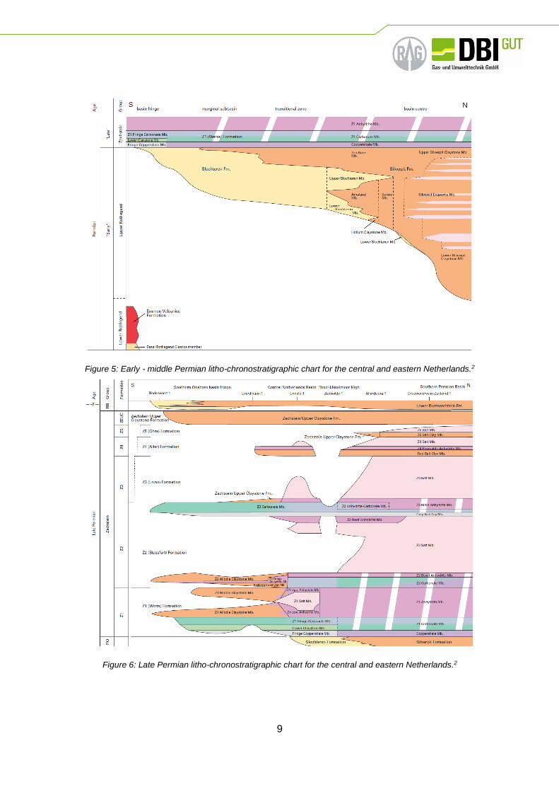
The underground gas storages in the Netherlands are located in the Upper Rotliegend or Zechstein
geological formations (see Figure 3), which were deposited in Permian times under warm and arid
climatic conditions over an area that is also known as the South-Permian Basin, which stretches
from England to Poland (Figure 4).
Figure 3: Schematic lithostratigraphy of the Dutch subsurface 2
The Upper Rotliegend Group (Figure 5), usually representing fluvial, eolian and playa-lake deposits3,
is a very prolific reservoir formation in the Netherlands and the rest of the South-Permian Basin. The
2 Van Adrichem Boogaert & Kouwe (1993-1997) Lithostratigraphy; https://www.dinoloket.nl/table; https://www.dinoloket.
nl/permian
3 Geluk, M.C. (2007) Permian In: Geology of the Netherlands, edited by Th.E. Wong, D.A.J. Batjes & J. de Jager, Royal
Netherlands Academy of Arts and Sciences, 2007: 63-83.

8
enormous Groningen gas field for example is located in these Permian sandstones of the Upper
Rotliegend Group as are the Grijpskerk, Norg and Bergermeer fields.
Figure 4: Permian Rotliegend Subcrio map of the Southern Permian Basin 4
The Zechstein geological formation on top of the Rotliegend comprises five evaporates cycles3
(Figure 6) of alternating carbonates, dolomites, anhydrites and salts. The massive salt layers form
an effective seal for the reservoirs in the Rotliegend and also act as a host to two of the cavernous
storages. Some of the carbonates and dolomites within the Zechstein have been known to be natural
gas reservoirs as is the Alkmaar UGS.
All these reservoir rocks are mainly sourced from a thick Upper Carboniferous, Westphalian
succession underneath, which comprises abundant coals and carbonaceous shales5 within the
Limburg Group.
4 Van Uijen, W.M. (2013) Rotliegend geology in the Southern Permian Basin: the development of synrift sediments and its
relation to seismic imaging.Utrecht University
5 De Jager, J. & Geluk, M.C. (2007) Petroleum Geology In: Geology of the Netherlands, edited by Th.E. Wong, D.A.J.
Batjes & J. de Jager, Royal Netherlands Academy of Arts and Sciences, 2007: 241-264.
9
Figure 5: Early - middle Permian litho-chronostratigraphic chart for the central and eastern Netherlands.2
Figure 6: Late Permian litho-chronostratigraphic chart for the central and eastern Netherlands.2

10
Figure 7: Depth of the base of the Zechstein Group (ZE) 6
The UGS of the Netherlands are all depleted gas fields found at a depth between 2 and 3 km below
the surface (Figure 7). The average temperature of the gas storages are therefore somewhat higher
than for example the underground gas storages in Austria, and can range from 70 to 115°C (Figure
8). The formation waters of the oil and gas reservoirs in the Dutch subsurface are usually quite saline
(average around >120,000 ppm with SO4 concentrations of around 80 ppm and a pH of around 6
6 TNO (2014) Diepte van de basis Zechstein Groep (ZE), DGM-diep V4 onshore.

11
(Figure 9) because of the depth, specific reservoir fluids and the presence of the Zechstein Salt).
The most important geological parameters of the porous storages are given in Figure 9.
Figure 8: Temperature at the base of the Zechstein (°C) 7
7 Bonté, D., Van Wees, J.-D. & Verweij, J.M. (2012) Subsurface temperature of the onshore Netherlands: new temperature
dataset and modelling, Netherlands Journal of Geosciences – Geologie en Mijnbouw, 91 (4), p. 491-515.

12
Figure 9: Statistical characteristics of the groundwater composition (mgl-1, with alkalinity as mg HCO3 l-1) of the Dutch subsurface 8
8 Griffoen, J., Verweij, J. & Stuurman, R. (2016) The composition of groundwater in Palaeogene and older formations in
the Netherlands. A Synthesis, Netherlands Journal of Geosciences – Geologie en Mijnbouw 95 (3) p. 349-372.

13
3.3 Pore reservoirs
General remarks
In the following tables (Table 1/Table 2) the geological and reservoir mechanical parameters of the
Dutch porous underground storages are shown:
Table 1: Geological parameters porous reservoirs in the Netherlands
Table 2: Reservoir mechanical parameters porous reservoirs in the Netherlands
Grijpskerk
This UGS, operated by NAM, with good reservoir properties is located in the Slochteren Formation
of the Rotliegend Group and is used to store high-calorific gas in the Dutch sub-surface. It is a classic
Storage Formation
short Formation long Main lithology Seal
Grijpskerk ROSL Slochteren Formation (Upper Rotliegend)
Sandstones Zechstein
formation (salt, clays)
Norg (Langelo)
ROCLT Lower Ten Boer
Member - Silverpit Fm - (Upper Rotliegend)
Sandstones Conglomerates
Zechstein formation (salt,
clays)
ROSL Slochteren Formation (Upper Rotliegend)
Sandstones Zechstein
formation (salt, clays)
Alkmaar ZEZ3B Zechstein Carbonate Member (Zechstein)
Dolomite/Limestone Zechstein
formation (salt, clays)
Bergermeer
ROSL Slochteren Formation - Weissliegendes (Upper
Rotliegend) Sandstones
Zechstein formation (salt,
clays)
Slochteren Formation - Rotliegendes (Upper
Rotliegend) Sandstones
Zechstein formation (salt,
clays)
Storage Woking
gas (bm3)
Net
(m)
Φ
(%)
Permeability
(mD)
Depth
(TVD NAP)
pini
(bar)
pwork
(bar)
Grijpskerk 2 220 19.5
average 50 mD
average -3300 392 257-384
Norg (Langelo) 7 140 18,5 ~550 mD -2670 328 225-347
Alkmaar 0.5 40 Up to 20 <10mD -2025 196 196
Bergermeer 4.1 200 12-20 20-80
-2200 238 75-135 20-30 100-5000

14
fault-bounded three-way dip closure (Figure 10). The main working storage area, which comprises
only about 10 % of the total gas initially in place, is located at the crest of the structure (Figure 11).
Temperature measurements from various wells indicate a rather high temperature regime in the field
of up to 115°C. The Grijpkskerk field is also the deepest UGS in the Netherlands.
Figure 10: Structural map top Slochteren Formation Grijpskerk 9
9 NAM B.V. (2010a) Update opslagplan UGS Grijpskerk

15
Figure 11: SW-NE geological cross-section from Grijpskerk 9
Norg (Langelo)
The UGS in the Norg field (Figure 12), also operated by NAM, is located in the Upper Rotliegend
Formation, in both the Lower Ten Boer Member, which has moderate reservoir properties as well as
the Slochteren Formation, which has the usual good reservoir properties. The compartmentalized
field is quite elongated, but as is the case for the Grijpskerk field, the main part of the storage is
located at the well-explored crest (Figure 13). As it is the second deepest UGS in the Netherlands
the temperature is also quite high (~95°C).

16
Figure 12: Structural map top Rotliegend Norg 10
10 NAM B.V. (2010b) Update opslagplan UGS Norg

17
Figure 13: Seismic line over the Norg gas field 5
Bergermeer
Operated by TAQA Energy BV, Bergermeer has the capacity of more than 4 bm3 (working gas
against a total GIIP of approximately 17 bm3) and its capacity will likely be increased considerably in
the future. It is located in the Upper Rotliegend and comprises both the Weisliegend, which has
moderate reservoir properties, as well as the Rotliegend, which has very good reservoir properties.
The field consists of two main fault blocks, located on a NW-SE trending horst block (Figure 15). The
original reservoir pressure was approximately 228 bar, but the storage is now operating between 77
and 133 bar as the original gas-production of the field had lowered the pressure considerably. The
formation fluids tend to be quite saline but as it is generally the case for the Rotliegend and Zechstein
reservoirs, they tend not to have a water drive. As the reservoir lies approximately at a depth of
2100 m below NAP temperatures remain generally below 85°C.

18
Figure 14: Geological cross section of the Bergermeer Field 11
Figure 15: 3D View of the Bergermeer field showing top Slochteren surface 12
11 TAQA Energy B.V. (2015) Gas Storage Bergermeer – Nout den Boer.
12 TNO (2008) Bergermeer Seismicity Study

19
Alkmaar
The Alkmaar UGS (also known as the Alkmaar Piekgasinstallatie - PGI -, operated by TAQA Energy
BV) is the only one of the porous underground gas storages located in the Z3 Carbonate Member of
the Zechstein Group (ZEZ3C). Generally, this member is a brownish, slightly argillaceous, dolomitic
limestone or coarse-crystalline dolomite, also known as the Plattendolomit. It is not as thick as the
Rotliegend storages (~50 m) and lies at a moderate depth between 1900 and 2100 m (Figure 16).
The porosity can get up to 20 % but as these pores are not very well connected, the permeability is
less than 10 mD. Fractures and stylolites in the reservoir rocks contribute to the overall porosity and
permeability. The seal is formed by overlying Zechstein salt and anhydrites.13. (Figure 17) The
reservoir is a three-way dip closure bounded by faults on three sides. The field has a working
capacity of approximately 0.5 bm3 (against a total GIIP of approximately 3.6 bm3) and is mainly used
for low calorific gas.
Formation water analysis of a neighbouring well (SRM-02, not in the field itself) collected from a Drill
Stem Test revealed that the salinity is quite high (~250,000 ppm) with a pH of ~5.7. Sulphate content
is around 220 ppm.14
13 BP Nederland Energie B.V. (2003) Verzoek om instemming voor opslagplan, opslagvergunning Alkmaar.
14 Pan American Petroleum Corporation (1965) Water Analysis DST No.1 – Bottom Schermer 2

20
Figure 16: Depth Map Top Platten Dolomite Alkmaar Field 13

21
Figure 17: Geological cross-section of the Alkmaar Field 13
3.4 Salt caverns
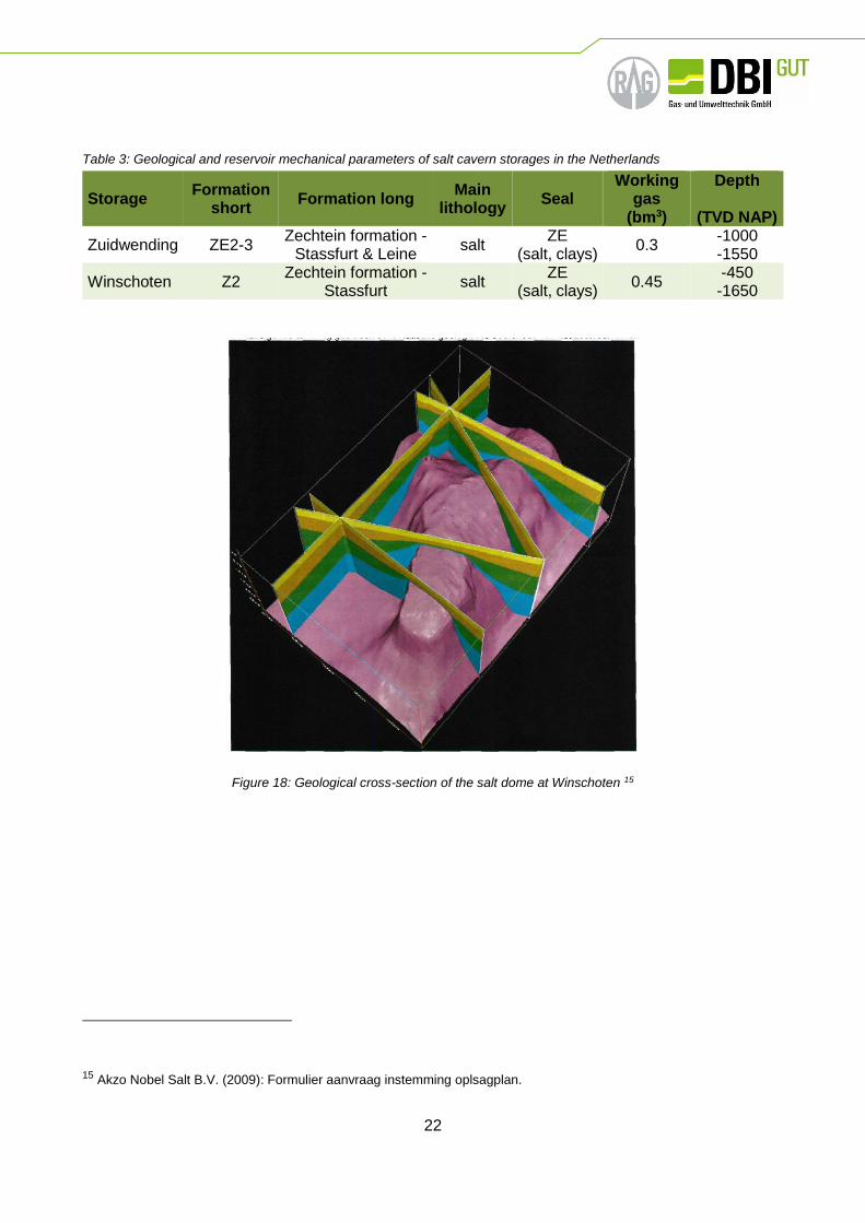
Zuidwending & Heiligerlee – Winschoten
These two UGS facilities, operated by EnergyStock BV and Akzo Nobel Salt BV (see Figure 18 for
some geological parameters), are man-made leached salt caverns at around 1000 m depth within a
salt dome of Zechstein Salt (Figure 18). The several caverns were specifically made for buffering
natural gas or nitrogen. The salt makes for a very effective seal all around and as no hydrocarbons
were present (only leached NaCl brine) it could be an ideal environment for storing different types of
gases or liquids. The total volume of a single cavern is quite small (~0.5-1.0 Mio m3) compared to
the pore reservoirs, which are used for UGS in the Netherlands.
22
Table 3: Geological and reservoir mechanical parameters of salt cavern storages in the Netherlands
Figure 18: Geological cross-section of the salt dome at Winschoten 15
15 Akzo Nobel Salt B.V. (2009): Formulier aanvraag instemming oplsagplan.
Storage Formation
short Formation long
Main lithology
Seal Working
gas (bm3)
Depth
(TVD NAP)
Zuidwending ZE2-3 Zechtein formation -
Stassfurt & Leine salt
ZE (salt, clays)
0.3 -1000 -1550
Winschoten Z2 Zechtein formation -
Stassfurt salt
ZE (salt, clays)
0.45 -450 -1650

23
General description of potential effects and damages in UGS facilities caused by hydrogen
4.1 General remarks
The following chapters 4.1 to 0 are more or less translated from the planned DVGW final report G 2-
02-13 “Wasserstoffverträglichkeit in Porenspeichern” which is in preparation by Bauer et al.16 A
comprehensive description of possible impacts and damages on underground gas storage (UGS)
facilities caused by hydrogen was conducted in two DGMK literature studies. The DGMK research
report 752, was prepared by the institute of petroleum and natural gas technology (“Institut für Erdöl-
und Erdgastechnik”) of TU Clausthal. It deals with the influence of hydrogen on UGS facilities.17
DGMK research report 756 deals with the influence of biogas and hydrogen on microbiology in UGS
and was prepared by MicroPro GmbH, Gommern.18 The statements in chapter 4.3 and 0 are mainly
based on these two publications.
Except for pure hydrogen caverns, there are no known examples of hydrogen storage in natural gas
UGS, e.g. hydrogen-natural gas mixtures. Here, however, the influence of other gas components
like carbon monoxide and oxygen must be considered, too. Further sources are other technical
applications, dealing with hydrogen in the underground or surface facilities. Conclusions from town
gas or other applications always must consider all boundary conditions like pressure, partial
pressure, temperature, water or condensate content, geo-chemical context, etc.
4.2 Tightness and hydraulic integrity of the cap rock
Natural gas reservoirs normally do not contain hydrogen, but hydrogenous town gas was indeed
stored in porous formations. No problems regarding tightness and hydraulically integrity of the cap
rock were reported at that time.19 None the less, hydrogen storage under the planned operational
conditions is a novelty due to its specific properties like molecular size and -weight. The geological
tightness of a porous formation cap rock against hydrogenous gas depends on the cap rock’s ability
to withstand gas infiltration mechanically and hydraulically.17
16 DVGW (2017). Abschlissbericht DVGW-Projekt G2-02-13; Wasserstoffverträglichkeit in Porenspeichern. Bonn: DVGW–
in preparation
17 Reitenbach, V., Albrecht, D., & Ganzer, L. (2014). Einfluss von Wasserstoff auf Untertagegasspeicher; DGMK Research
Report 752. Hamburg: DGMK
18 Wagner, M., & Ballerstedt, H. (2013). Einfluss von Biogas und Wasserstoff auf Mikrobiologie in Untertagegasspeichern.
Hamburg: DGMK
19 DVGW. (2013). Abschlussbericht DVGW-Projekt G1-07-10; Entwicklung von modularen Konzepten zur Erzeugung,
Speicherung und Einspeisung von Wasserstoff und Methan ins Erdgasnetz. Bonn: DVGW

24
Permeability needs to be considered as well as diffusion and solution processes. A decisive factor
is also the water saturation of the cap rock, differing from reservoir to reservoir.17
Hydrogen must dissolve into the formation water of the cap rock, when diffusing through the cap
rock. The diffusion is dependent on the concentration gradient, where the maximum concentration
of a gas component is dependent on its solubility in water. The solubility of hydrogen in water is
lower than in methane, but the diffusion ability is four times higher. No directly comparable diffusion
coefficients of hydrogen and methane are reported in the literature, it is however assumed that both
are of similar range. Large-scale methane losses by diffusion are not expected in former natural gas
reservoirs (which are now used for storage), because the formation water in the cap rock was
saturated with methane over geological periods and due to that, there is only a very small gradient.
For storage of hydrogen, this gradient exists in the beginning and its value depends on the hydrogen
content in natural gas. Despite the fact that diffusion is a slow process, small initial losses need to
be considered at the beginning of hydrogen storage. Those losses appear until the formation water
in the adjacent cap rock is saturated with hydrogen. Hydrogen losses in the range of 2 % over the
life cycle of a UGS have been reported.17
A physically different process is the permeability of the cap rock. Here it has to be considered that
the pore volume of the cap rock is saturated with water and the sealing is caused by capillary
pressure, which should not be exceeded. The influence of hydrogen on capillary pressure has not
been reported yet – it is assumed it depends on the interfacial tension between water and
hydrogen17, which is similar methane and water systems.20
4.3 Geochemical reactions
During storage of hydrogen, there is the risk to trigger geo-chemical reactions with rock minerals and
reservoir fluids. Those reactions could on the one hand lead to energy losses, and on the other hand
to further undesirable effects: reactions with rock minerals could lead to damage in the rock and
mineral structure, resulting in the alteration of crucial reservoir properties like pore volume and
permeability.
For example, the reaction of hydrogen with carbonates is possible, and further reactants are
sulphates, sulphides and oxygens.17 In general, geo-chemical reactions with minerals are considered
to be slow and less relevant for gas storage operations,21 respectively reservoir temperatures are
not high enough to activate these reactions17. Microorganisms might act as a catalyst for such
operations and are described in chapter 0.
20 Wiegand.(1994). Interfacialtension between water and non-polar fluids up to 473 K and 2800 bar. US:
Ber.Bunsenges.Phys.Chem.98, 809-817 (1994) No6.
21 Pichler, M.(2013). Assessment of Hydrogen Rock Interaction During geological Storage of CH4-H2 Mixtures
(Bd.MasterThesis). Leoben: Montanuniversität Leoben

25
4.4 Changes in transport mechanisms in the reservoir
The physical properties of hydrogen and methane (natural gas) are fundamentally different.
Therefore, they need to be investigated, whether there are alterations in dispersion and distribution
of the gas in porous formations. Possible interactions with the cushion gas need to be considered.
4.5 Microbiological reactions
Under anaerobic conditions, hydrogen is an easy to utilize source of energy, which can be used by
numerous microorganisms. It must be assumed that porous natural gas UGS are not sterile, with
very few exceptions. Microorganisms either exist naturally in the reservoir or were introduced during
drilling and workovers.
Under sterile conditions, numerous different microorganisms can cause several anaerobic metabolic
processes. Sulphate reducing, methanogenic and acid-forming prokaryotes are identified as major
participants18. Here, hydrogen serves as electron-donator, and the availability of a respective
electron-acceptor is the precondition for the reaction. Popular reaction equations are as follows:
4𝐻2 + 𝐶𝑂2 → 𝐶𝐻4 + 𝐻2𝑂
4𝐻2 + 2𝐶𝑂2 → 𝐶𝐻3𝐶𝑂𝑂𝐻 + 2𝐻2𝑂
4𝐻2 + 𝑆𝑂42− + 2𝐻+ → 𝐻2𝑆 + 4𝐻2𝑂
Depending on the predominant type of metabolism, the microbiological utilization of hydrogen can
lead to significant pressure losses and economical relevant loss in heat value, as well as to several
negative impacts on operation regime and safety of UGS. Following risks are identified for porous
UGS18:
Corrosion and acidification of the reservoir fluids through accumulation of hydrogen sulphide
(H2S) and organic acids
Decrease of permeability through iron sulphide (FeS) precipitation, biofilms and extra-cellular
substances
Reduction of gas quality through hydrogen consumption and hydrogen sulphide (H2S)
formation
Microbial induced corrosion
Stimulation of microbial processes through additional hydrogen energy potential
Precipitation respectively solving of matrix-components (carbonates)
Sedimentation of sulphur / biofilms in surface facilities through increased hydrogen sulphide
(H2S) share in the withdrawn gas

26
From above statements, it can be easily concluded that the availability of sulphur has a decisive
negative impact on the possibility of hydrogen gas admixture to natural gas. Energy losses and
undesired concomitant phenomena seem to be unavoidable. On the other hand, VNG reports from
gas storage operations of town gas in former porous gas reservoirs that have a certain buffer
potential for hydrogen sulphide (H2S), which was not fully exploited during the town gas storage and
the operational impacts were limited.19
If carbon dioxide (CO2) is available, it can lead to methane generation., This goes hand in hand with
a loss of gas volume, reservoir pressure as well as heating value. However, the metabolite methane
is applicable in the existing infrastructure and consumer structure. There are various activities in
Europe aiming to utilize these processes.
4.6 Technical integrity / reliability of material
Introduction
In the case of natural gas underground storage the secure injection- and production cycle has to be
guaranteed at all times. The main aspect therefore is that the occurrence of uncontrolled gas
leakages in all parts of the borehole completion and surface facilities has to be avoided during all
parts of the operation phases. This process, also known as borehole integrity, is the total of all
procedures that are ventured during planning, drilling and usage of an underground storage well, to
guarantee the injection and production of fluids as well as the leak tightness. Therefore, a lot of
technical, operational and organizational procedures and solutions are needed.17 The introduction
of certain amounts of hydrogen in the low gas distribution system implicates more engineering work
to warrant the borehole integrity. Hydrogen gas consists of small atoms and molecules. This allows
hydrogen to diffuse through almost any material. Because of this specific property, the technical
installation in UGS, consisting of steal alloys, cements and elastomer packers, has to be able to
withstand damage caused by hydrogen.
There has already been research on hydrogen resistance of materials used in the gas grid which
seem to have no issues with hydrogen. A question which is still open is the materials and operational
states of UGS facilities. They are dealing with wet gas during their production cycle which puts
additional strain on the materials. That is the reason why the materials used in the underground
storage industry are specific and not presented in other parts of the gas infrastructure. The borehole
completion of porous reservoirs and cavern storages is equal in most of their components, but they
deal with different corrosion issues during injection and production. In case of porous reservoirs, the
gas is stored in depleted gas fields or aquifer formations. The stored gas is in contact with other
substances like reservoir fluids, water, bacteria and trace gases. The chemical and microbiological
reaction potential is higher than in caverns, which means the materials of the borehole completion
in porous UGS have to be resistant against products of reactions within the storage (e.g. hydrogen
sulphide), as well as hydrogen itself. These phenomena are not so important in cavern storages,
because the gas is stored in artificially produced cavities within salt deposits. The chemical and
microbiological reaction rates are lower than in porous UGS, because of less contact with water, less
microbiological activity and higher salinity of the water within caverns. However, cavern storages
operate at higher pressures and higher changes in operation modes, which has an additional impact
on stresses within the borehole completion.

27
Besides the theoretical integrity losses caused by pure hydrogen, which has been discussed above,
it also has to be considered that hydrogen is able to react chemically and biologically with sulphurous
minerals within the underground storage. The product of these reactions is the hydrogen sulphide
(H2S) that forms a weak acid when dissolved in water and is a source of hydrogen ions and highly
corrosive. The hydrogen sulphide resistance of existing borehole completions is well known in the
oil and gas industry. The materials used for oil and gas facilities with parts of hydrogen sulphide are
represented in the API specification 5CT, 5L and 6A.22,23,24
In general, it can be said that materials with hydrogen resistant properties exist and can be used to
secure the technical integrity of UGS wells. What is not known is the hydrogen resistance of existing
borehole completions that have been used for natural gas underground storages in the past years.
The hydrogen resistance of material in borehole completions of underground storages can be divided
in three groups:
Integrity of steel alloys
Integrity of cementation in UGS wells
Integrity of elastomers and seals
Integrity of steel alloys
The investigation of all materials used in UGS wells is needed to evaluate the technical integrity.
One of the main components mentioned above are the steel alloys that are in contact with hydrogen
gas during injection- and production. An UGS well contains steel alloys that are in direct contact with
the storage medium, e.g. inner casing, tubing, subsurface safety valve, packers and so on. All these
elements have to be resistant against hydrogen influenced impairments in a wide temperature and
pressure range. The influence of hydrogen to the properties of steel alloys was analysed in several
research papers before. The often-recognized influences, that have an impact on the properties of
steel alloys, are hydrogen blistering, hydrogen induced cracking (HIC) and hydrogen embrittlement.
Beside the main properties of steel, also temperature, pressure, hydrogen concentration and stress
fields are able to influence the above phenomena.17 The metal-based materials that are used in the
natural gas distribution system are tested and investigated in several research projects. The results
were that hydrogen blending of up to 10 % has no critical impact.25 In the area of borehole completion
of UGS wells steel with a high tensile strength is used, which is susceptible for hydrogen
embrittlement. During the completion work the tubing is pre-loaded so that the integrity loss by
compressive stresses is avoided. Additionally stress changes in the borehole completion, especially
22 API Specification 5CT ISO 11960:2004: Petroleum and natural gas industries—Steel pipes for use as casing or tubing
for wells
23 API Specification 5L ISO 3183:2007: Specification for Line Pipe
24 API Specification 6A ISO 10423:2001: MOD, Petroleum and natural gas industries—Drilling and production equipment—
Wellhead and christmas tree equipment
25 DVGW report (2014). Anschlussbericht DVGW Projekt G1-02-12; Wasserstofftoleranz der Erdgasinfrastruktur aller
assozierten Anlagen. Bonn: DVWG

28
thermal and pressure changes during operation can accelerate hydrogen embrittlement within the
tubing. Furthermore higher encroachment obtain within underground gas storages, because of the
wet conditions and the salinity of reservoir fluids. Under these specific circumstances there are no
results or statements about the influence of hydrogen on steel alloys published yet.17
Integrity of cementation in UGS wells
The cementation of UGS wells is the connection between casing (steel) and formation (rock). The
main challenges are the anchorage of the casing with the formation, the prevention of gas leakage
through the cement bond into the formation and the stabilization of the borehole completion. This
cement bond has to be resistant against storage gas as well as tight enough that gas cannot diffuse
through it into other formations or even worse, to the surface. Because hydrogen molecules are
smaller than the methane molecules, which are nowadays stored in underground storages, leaking
paths through the cement and along the cement-bond need to be avoided.
This means that the proper cement settling measures have to be applied in order to prevent leakage
paths between cement and casing, casing and formation as well as the generation of paths within
the cement itself. Like for every other gas two transport mechanisms can be identified for hydrogen.
One is the permeable mass flow because of pressure differences throughout the pores and the other
is diffusion which happens because of saturation gradients. Due to the fact that the pores of the
cement are mostly filled with water, the only viable transport mechanism in this case is, like in the
cap rock, the diffusion. The diffusion as was already mentioned is dependent on the solubility of the
diffusing source (hydrogen) and should therefore not be considered as overly critical. Generally
speaking it can be said, that the diffusivity of hydrogen decreases with increasing water saturation
in the cement.17
Furthermore it needs to be investigated whether the cement changes chemically due to the contact
with hydrogen. However research has already been done on this issue ant the risk of chemical
alteration is considered as low.17
Integrity of elastomers and seals
In the underground gas storage industry elastomers are used in the field of packers and fittings, in
order to seal off the annulus between tubing and casing. Generally, there are sealing elements that
are resistant against hydrogen and are already used in the hydrogen industry. It still has to be
investigated whether the commonly used elastomers in UGS wells are able to resist the diffusion of
hydrogen. If hydrogen penetrates these elements a possibly integrity loss as a result of a quick
decompression may happen. In this case, an inner blister fracture can lead to loss of integrity,
because the hydrogen quickly expands within the material.17 This effect is dependent on the partial
pressure and can also happen in the storage facilities of other gases, but the difference regarding
hydrogen is the its higher diffusivity. Usually sudden decompression does not happen in gas storage
facilities. It is only a viable scenario in case of severe accidents.

29
4.7 Operational effects
Besides the questions of technical, chemical and microbiological integrity of UGS there are further
operational effects and regulatory framework that need to be analysed in order to blend hydrogen
into the natural gas distribution system.
In case of the regulatory framework it has to be questioned whether any contracts or permissions
regulate the underground storage of hydrogen or natural gas-hydrogen mixture? Otherwise, if
necessary, adaptations need to be made
Hydrogen has a lower energy content than natural gas, which means the more hydrogen is blended
to the storage fluid, the less energy can be stored, compared to natural gas storages. Another point
is that hydrogen increases the expenditure for turbines and compressors, because of its different
thermodynamic properties compared to methane.
The above-mentioned microbial conversion of hydrogen into other gases leads to energy losses,
which can be used (in case of methanation) or lead to more technical problems that need to be
calculated (in case of hydrogen sulphide production). The loss of energy has to be considered for
commercial and operational deliberations. Beyond that, it can come to pressure losses, water cuts
and possible temperature changes within the UGS.
4.8 Experience with town gas storage in Europe
Hydrogen storage was done in terms of town gas storage in countries like Germany, France,
Belgium, Czechoslovakia and Poland, in order to guarantee the supply, until 1990. At that time 8 of
the 13 aquifer reservoir storages, 3 of the 15 depleted gas field storages and 2 of the 19 cavern
storages in Germany were operating with town gas. Nowadays all of them are either operating with
natural gas or are closed. Thereby town gas with a hydrogen content of up to 55 vol.-% was stored
in different UGS locations. The storage conditions (pressure and temperature) were comparable to
today´s underground natural gas storages. The storage process was possible, although it caused
problems in some of the aquifer reservoir storages, e.g.:
gas volume losses,
corrosion,
reservoir temperature increase
and gas quality changes
These operational problems were not only caused by hydrogen. The gas volume losses in aquifer
reservoirs are not clarified until today. Furthermore, the gas composition of town gas is more complex
than hydrogen enriched natural gas. Besides hydrogen, also gases like carbon dioxide (15 vol.-%)
and oxygen (0.5 vol.-%) caused chemical and microbiological reactions within the aquifer reservoirs,
which consequently caused corrosion within the borehole completion. Hydrogen sulphide, as a
product of the reaction between sulphate-reducing bacteria and hydrogen, was one of the corrosion
substances. Additionally, hydrogen sulphide can precipitate as insoluble sulphide, which has an

30
impact on permeability within the near borehole region. The underground storage of town gas in
depleted gas fields and caverns caused less technical problems. In caverns, the potential of chemical
and microbiological reactions were not as high as in porous reservoirs.
The experience with town gas storage in Germany, has proven that the storage of hydrogen-enriched
natural gas is possible and viable, but the following aspects need to be considered:26
As a result of different reactive components within the composition of town gas the
transformation of the results to the storage of hydrogen enriched natural gas is limited
The population of sulphate-reducing bacteria is different within every UGS. The production
of hydrogen sulphide depends on the concentration of these sulphate-reducing bacteria and
hydrogen can cause the growth of these bacteria,
Both the underground storage of hydrogen-enriched natural gas and surface equipment (gas
turbines, gas quality measurements) has to be monitored and expansions for hydrogen
sulphide separation may have to be adapted.
The operation costs for underground hydrogen storages can be higher, because of increased
arrangements to avoid hydrogen embrittlement within the technical equipment of the
borehole completion.
Furthermore, gas losses through migration and bacteria growth have to be considered.
The energy storage capacity of the storage decreases when the amount of hydrogen in the
system increases.
The literature of town gas storages contains no specific information about safety and technical
regulations of materials that can be used for future hydrogen enriched natural gas storage.27
26 DVGW report (2013): Entwicklung von modularen Konzepten zur Erzeugung, Speicherung und Einspeisung von
Wasserstoff und Methan ins Erdgasnetz
27 Final report (2014). Integration von Wind-Wasserstoff-Systemen in das Energiesystem, Nationales
Innovationsprogramm Wasserstoff- und Brennstoffzellentechnologie

31
Hydrogen content up to 0.5 %
5.1 General remarks
According to the general description of potential effects and damages in UGS facilities caused by
hydrogen in chapter 4 in this chapter the potential effects of hydrogen admixtures of 0.5 % are
discussed in detail. All issues are handled referring mainly to UGS in depleted gas field and caverns
which are the storage formations used in the Netherlands.
The admixture of up to 0.5 % of hydrogen to natural gas leads to a maximum partial pressure of
hydrogen of 2 bar at UGS Grijpskerk, which is the storage with the highest maximum reservoir
pressure. The partial pressure is relevant for all the following issues as it is most of the times the
governing factor of whether or not hydrogen has an effect on mechanisms like diffusion or
embrittlement of steel grades. All other effects like temperature or salinity are given with general
thresholds and can be referred to the geological introduction in order to determine its relevance for
a given storage facility.
5.2 Tightness and hydraulic integrity of the cap rock
For the porous reservoirs used as UGS an important fact is the tightness of its seal preventing gas
from escaping into adjacent layers. For the storages of the Netherlands, theses seals are usually
made up of overlying salt or clay/salt layers. They are several hundred meters thick and have proven
their tightness over millions of years by containing the gas that was initially found in the gas reservoirs
below. There is a third kind of seal known which are sealing faults. As far as we know none of the
Dutch UGS have this kind of seal. The aim of this chapter is to elaborate on the tightness of the seal
against hydrogen intrusion as well as the stability of the seal against hydrogen induced changes.
Clay
The overlying Zechstein formations of Netherlands gas storages consist of water saturated clay and
salt stones. Generally, the water-saturation in the cap rock can always be considered to be 100 %.
This is important to know and should eventually be checked when developing new gas storages as
the diffusion speed of gas is directly dependent on the water saturation. Clay and salt rocks are
generally considered to be gastight against gas flow, because of their low permeability and small
pores. The governing factor is the capillary pressure, which as long as it is not exceeded prevents
gas from flowing through the seal. As a general rule of thumb it can be said, that as long as the initial
reservoir pressure is not exceeded, the capillary pressure will also not be exceeded. Therefore, the
only mechanism, which allows gas, in this special case hydrogen, to travel through the seal, is
diffusion. The diffusion speed depends strongly on the solubility of gas. In chapter 5.3.1 it will be
shown, that the solubility of hydrogen is lower than that of methane. However, the water in the
reservoir seal is not yet saturated with hydrogen, which means that there is a saturation gradient and
hydrogen will start diffusing into the sealing cap rock. Here the capillary pressure is also interesting,
as it influences the surface tension of the water droplets contained in the seal. The higher the surface
tension, the more problematic it is for a gas molecule to enter a water droplet. In dry porous media

32
the diffusion speed of gas into gas is about 0.05 cm/min. However, for 100 % water-saturated porous
media, this is decreased by a factor 1000 for sandstone, and up to a factor of 108 for clay. This
means that one hydrogen molecule could travel about 2.6-4 cm/year through water-saturated clay 28.
This is also proven by the nuclear waste repository research, where the use of clay barriers to
prevent migration of hydrogen, which is generated by the degradation of nuclear waste, was
investigated. Those water saturated barriers are designed to prevent hydrogen from traveling
through them for up to 100.000 years 29,30
Also keeping in mind that the partial pressure of hydrogen in this case is very low, it can be said, that
the risk of hydrogen diffusing into and through the cap rock is very small. Technical gas tightness is
given.
The influence of hydrogen on the geochemical behaviour of clay rocks has also been extensively
investigated in the nuclear waste repository research. There is the issue of change in pH-value that
has been monitored. However, this is even a positive thing for the overburden clay, as the clay
minerals tend to swell if salinity or pH-values are changing, which might lead to a further decrease
of permeability.
As the solubility of hydrogen is lower than the solubility of methane, it can be summarized that the
tightness of clay against hydrogen migration and intrusion is at least as high as that of methane and
therefore there is no integrity issue for hydrogen admixtures up to 0.5 %. There is a certain economic
risk of one-time losses, which will occur due to some of the hydrogen dissolving into the water of the
cap rock. However, this risk can be estimated if the area of the cap rock, the composition of the
reservoir water and the capillary pressure of the cap rock is known.
Faults
There are reservoirs, which are sealed off by faults that have formed over geological time and are
linked to the formation of the reservoirs. These faults are usually also filled with clay or very fine rock
residues and are gastight. Most of the issues discussed for a clay seal can also be applied to sealing
faults. If the fault however is not perfectly tight, gas might start to migrate through such faults.
However, this would be an issue for the whole storage and not only for hydrogen, which could be
proven in the Underground Sunstorage project that will be published in 2017. The Underground
Sunstorage project as well as other papers about the storage of hydrogen natural gas mixtures also
confirmed that the travel speed of hydrogen and methane in a porous media is roughly the same.
28 Chen, & al, e. (1977). Binary Gas Diffusion of Methane-Nitrogen Through Porous Solids. Michigan, US: AlChE Journal
(Vol. 23, No. 3).
29 Galle, T. (1998). Evaluation of Gas Transport Properties of Backfill Materials for Waste Disposal: H2 Migration
Experiments in Compacted Fo-Ca Clay. Japan, France: Clays and Clay Minerals. Vol. 46, No. 5, 498-508.
30 Lassin, & al, e. (2011). Hydrogen solubility in pore water of partially saturated argillites: Application to Callovo-Oxfordian
clayrock in the context of a nuclear waste geological disposal. Fontenay-aux-Roses, France: Physics and
Chemistry of the Earth 36 (2011) 1721–1728.
33
This means that such a failure would be a general issue for UGS of all kinds and is not only limited
to hydrogen.
Salt
Rock salt has elastic-plastic properties and the ability to creep under pressure. The gas tightness of
salt has been proven over millions of years by the existence of natural gas reservoir under the
Zechstein formation (rock salt formations that are fluid- and gastight).31 The depleted gas field
storages of the Netherlands are all sealed off by this formation. Without the gas tightness of salt
these reservoirs would not have existed nowadays. Additionally all cavern storage projects use the
abilities of rock salt formations to create artificial cavities, which are gastight and can be used for
UGS.
Permeability tests with different gases (methane, carbon dioxide and nitrogen) have shown that the
tightness of salt formations can be used for storing several gases. The permeability of rock salt
formations is very low, within the range of 10-17 to 10-21 m2.33 Results are published in several
research papers.31,32,33 Current research projects for permeability measurements of rock salt in
hydrogen environment are running and first results will be published in 2018.
The low permeability doesn´t imply that no gas is entering the salt matrix. Several research projects
have proven that gas is able to enter the salt matrix along the grain boundaries of salt. This process
is known as percolation.34 The percolation can lead to losses in tightness and hydraulic integrity of
rock salt formations. In case of cavern storages this phenomenon infects the cavern nearest region.
Therefore geo-mechanical investigations and simulations are done to prevent hydraulic integrity
losses within the cavern storage. The amount of gas percolation into the salt matrix varies with the
depth, temperature and location of the storage cavern. In order to guaranty the hydraulic integrity
and tightness of caverns, this process has to be considered during planning and operation in order
to guarantee the save operation of cavern storages. Experience from the storage of town gas in salt
caverns has proven that up to 50 vol.-% of hydrogen is possible. Furthermore, no measurable gas
losses could be determined. (chapter 0).
31 Schmitz, Steffen; Lubenau, Udo; Kretzschmar, Hans-Jürgen;Rockmann, Rico; Kleinickel, Cindy; Bock, Peter; Rafiee,
Mohsen (2012): Long-term and safe sealing / -abandonment of wells in CO2 storage using CO2 resistant deep
drilling cements and natural materials; Project: Sealing of wells of a CO2 storage facility for long-term
abandonment CODICHT) – GEOTECHNOLOGIEN,
32 Lubenau, Udo Schmitz, Steffen (2012): Joint project CLEAN : Research Focus Well Integrity and Geo Modeling,
33 Wei Liu, Nawaz Muhammad, Jie Chen., C.J. Spiers, C.J. Peach, Jiang Deyi, Yinping Li. (2016): Investigation on the
permeability characteristics of bedded salt rocks and the tightness of natural gas caverns in such formations
34 Pierre Bérest, Mehdi Ghoreychi, Faouzi Hadj-Hassen, Michel Tijani (2012): Mechanical Behavior of Salt VII, Proceedings
of the 7th conference on the mechanical behaviour of salt, Paris, France,

34
5.3 Geochemical reactions
Dissolution
When injecting gas mixtures containing hydrogen into subsurface formations, shares of the gaseous
hydrogen will dissolve into the reservoir liquids (oil, water, gas) until reaching physical equilibrium.
However, it should be noted that the solubility function is depending on pressure and temperature.
For UGS, temperature variations can be an issue as it also varies throughout the different storages.
Fortunately, the solubility of hydrogen has a minimum at around 100°C which means that for the
comparably warmer reservoirs of the Netherlands only minor issues are expected.35 There are also
wide pressure variations through the different storages. Additionally for the given case of 0.5 % of
hydrogen in the mixture, the partial pressure, which is the governing factor in this calculation, has a
maximum of 2 bar in the Grijpskerk field. For higher shares of hydrogen this would increase
accordingly.35
This means that especially when starting a hydrogen operation in a field, one time losses will occur.
This would be an issue for aquifer storages or depleted gas storages with a strong water drive (e.g.
Norg Langelo), where the water saturation is high at the beginning of the operations, but does also
affect volumetric depleted oil and gas reservoirs. There is experimental data on dissolution of
hydrogen into tap water in the literature as well as some equations of state (e.g. GERG 2008), which
properly model hydrogen and hydrogen containing gas blends for various p-T-conditions.
Earlier studies36,35 found that the dissolution of hydrogen into tap water is the same order of
magnitude than for methane in molar unit. For example at 100 bar and 50°C, 0.079 mol35 of
hydrogen would dissolve into one kilogram of water where else for methane it would be
0.0807 mol/kg water.36 In mass units, the solubility of hydrogen is one order of magnitude lower
than for methane. The dissolved hydrogen is 0,16 gH2/kgH2O and the dissolved methane is
1,3 gCH4/kgH2O. It has to be noted, that this is only true if 100 % of hydrogen is presented. For any
lower concentration of hydrogen the amount of dissolved hydrogen decreases. This happens
because the solubility of gases correlates with their partial pressure in the gaseous phase.
For brines, Lassin et al30 proposed quite similar results when doing research on the Callovo-
Oxfordian clay rock. Recently the H2Store project published new insights on this topic and presented
preliminary results on the dissolution issue37. It indicates that the molar solubility of hydrogen in
brines might be higher than the solubility of methane. This would further increase the issue of one
35 Pray, & al, e. (1951). Solubility of Hydrogen, Oxygen, Nitrogen, and Helium in Waterat elevated temperatures. Columbus,
Ohio: Atomic Energy Comission.
36 Duan, & al, e. (1992). The prediction of methane solubility in natural waters to high ionic strength from 0 to 250°C and
from 0 to 1600 bar. US: Geochimica et Cosmochimica Acta Vol. 56.
37 DeLucia, & al, e. (2015). Measurements of H2 solubility in saline solutions under reservoir. GFZ Potsdam, Geochemistry.
Potsdam: Energy Procedia 76.

35
time losses in the first place and should be considered when injecting hydrogen for the first time into
a reservoir.
For gas storages, which are located in depleted oil reservoirs, there is also the issue of solubility of
hydrogen into the oil. Torres et al38 predicts the solubility to be around 1.5 mol.-% at 100°C and
150 bar. These values are taken form the chemical industry, but similar experience from CCS and
EOR is already available for subsurface reservoirs.39
Finally, parts of the hydrogen will mix with the cushion gas. From the literature, values from 1-3 % of
the injected gas are known to “dissolve” into the cushion gas.40. This was investigated in some gas
storages, where it was tried to replace parts of the cushion gas with inert gas. There are also
examples from town gas aquifer storages in France (Beynes), where low value town gas was kept
as cushion gas and natural gas was injected as working gas.41. After several injection and withdrawal
cycles only 1 % of the cushion gas was produced with the working gas, which clearly indicates that
mixture of both gases will only have a minor effect. In the end this does not really influence the safety
or the economics of the gas storage as the cushion gas in most storages is recoverable.
Summing up, it can be expected that some parts of the injected hydrogen will dissolve into the liquid
reservoir fluids. These amounts have to be taken into account when planning an injection of
hydrogen into natural gas storages. It will affect the capital expenditure as this gas will be a onetime
loss during the first storage cycle until the liquid reservoir fluids are saturated with hydrogen. This
holds true for any kind of amount of hydrogen, which would be injected into a reservoir so in later
chapters it will be just referenced.
Changes of the reservoir brine due to dissolution
The share of hydrogen which will dissolve into the reservoir brine can alter the composition of the
brine. From the literature it is known that below 130°C dissolved hydrogen slightly increases the pH-
value of the reservoir fluid.21 Other effects as significant changes in density or viscosity are not
known.
38 Torres, & al, e. (2013). Improving the Modeling of Hydrogen Solubility in Heavy Oil Cuts Using an Augmented Grayson
Streed Approach. Institut Francais du Petrol. France: Revue d'IFP Energies nouvelles.
39 Mori, & al, e. (2011). Evaluation of the potential of microbial restoration of natural gas deposites with CO2 Sequestration
by investigating indigenous bacteria in a high CO2 content oilfield. Jakarta: SPE 145898.
40 Srinivasan, B. S. (2006). The impact of reservoir properties on mixing of inert cushion and natural gas in storage
reservoirs. Morgantown, West Virginia, US: Department of Petroleum & Natural Gas Engineering, College of
Engineering and Mineral Resources, West Virginia University.
41 Foh, & al, e. (1979). Underground Hydrogen Storage Final Report. US: DOE.

36
Hydrogen impact on dissolved ions
Reservoir brines are quite heterogeneous and contain many different dissolved ions (Table 4).
Usually chemical reactions only happen in the liquid phase as the solid and the gaseous phase tend
consist of stable compounds. Therefore, the knowledge of the ions in the reservoir brine is quite
important as there are some which can potentially react with hydrogen. The potentially harmful ions
are dissolved iron and dissolved sulphur. Iron ions (Fe3+) can react to iron-hydroxide, which would
precipitate and could potentially plug pores. Sulphur could react to hydrogen sulphide (H2S), which
is a potentially harmful gas that can also cause corrosion. Nevertheless, it is found in the literature
that these reactions would only happen very slowly at the given temperatures in the reservoir.42.
Additionally a high share of carbonates will buffer these reactions.21 In the discussed case of 0.5 %
of hydrogen, the volume potential of hydrogen should be too low to have any measurable effects on
the reservoir brine.
Table 4: Dissolved species from the Well KBB-02 in the Kommerzijl field near Grijpskerk
42 Truche. (2009). Experimental reduction of aqueous sulphate by hydrogen under hydrothermal conditions: Implication
for the nuclear waste storage. Geochimica et Cosmochimica Acta 73 (2009) 4824–4835: Elsevier.
pH 5.8
Boron 280 mg/l
Borate 150 mg/l
Bromide 200 mg/l
Chloride 91000 mg/l
Sulphate 170 mg/l
Calcium 9900 mg/l
Iron 150 mg/l
Potassium 1600 mg/l
Magnesium 1300 mg/l
Sodium 44000 mg/l
Silicon 20 mg/l
Barium 16 mg/l
Manganese 29 mg/l
Nickel 4.7 mg/l
Lead 22 mg/l
Strontium 360 mg/l
Zinc 83 mg/l
Total fixed CO3 1400 mg/l
Carbon Dioxide 790 mg/l
Bicarbonate 290 mg/l
Silicate 1.5 mg/l
37
Dissolution and precipitation of reservoir rocks
As for the dissolved ions the reservoir rock as well as the sealing clay rocks can be a source for
elements which could possibly react with hydrogen in the aqueous phase. When hydrogen reacts
with the ions in the water, the geochemical equilibrium as well as the pH value is changed resulting
in the dissolution or precipitation of minerals depending on the reaction product. However, for a
concentration of 0.5 % of hydrogen the potential for reactions is rather low.
5.4 Changes in transport mechanisms in the reservoir
At a level of 0.5 % hydrogen admixture no significant or measureable changes in transport
mechanisms in the reservoir are expected. In the course of the Underground SunStorage research
campaign laboratory test upon possible differences in travel speed or even gravimetric segregation
have been performed. Results should be published in 2017.
This holds also true for the sealing clay or salt rock. Here several experiments have been done which
identified the permeability of dry clay for hydrogen and natural gas. It was assumed, that the
hydrogen due to its smaller molecule size would travel faster through the formation than natural gas.
However, the important factor in this case is not the molecule size, but the difference in viscosity.
This difference was found to be insignificant and therefore it can be assumed that both gases travel
at the same speed through the porous reservoir. Still there should be a scientific investigation as the
viscosity changes with pressure and might change stronger for natural gas than for hydrogen due to
its unique physical properties (negative Z factor).
5.5 Microbiological reactions
It is common knowledge that subsurface formations contain microbes. They can either be
autochthonic or anthropogenic. The first kind was buried in the reservoir millions of years ago when
the sediments forming the reservoir were deposited. The second kind was brought into the reservoir
by artificial means. This can either be during drilling when drilling mud is contaminating the reservoir
or during workover operations in the borehole. There are extreme examples from the North Sea
where the injection of seawater lead to the generation of massive amounts of hydrogen sulphide
(H2S).
For the Dutch storages this has to be taken into consideration when thinking about the injection of
hydrogen. Some of these microbes are able to metabolize hydrogen and therefore reduce the
hydrogen content of the gas, which would lead to energy losses. Generally speaking, microbes
present in the subsurface can be often characterised as thermophilic, anaerobic, barophilic (-
tolerant) and halophilic (-tolerant).17,18 For the given storages the thermophilic and the halophilic
microorganisms are of special interest, as they are capable of surviving under high temperatures (up
to 90°C) and high salinity levels. From this perspective, Grijpskerk should be safe from microbial
influence (~115°C reservoir Temperature) and Norg (Langelo) (~95°C reservoir Temperature)
should also have no microbial issues as the microbes tend to be in a dormant state when
temperatures become too high.

38
However, Alkmaar and Bergermeer are in a temperature range (around 80°C) where microbial
activity could still be an issue. Hydrogen is for some bacteria an easily available and digestible
energy source and can support their growth. The German H2Store project did laboratory
experiments on microbes in high saline reservoirs. They found three possible reactions occurring
with microbes, namely methanogeneses, acetogeneses and sulphur reduction. Methanogeneses is
the reaction of hydrogen (H2) und carbon dioxide (CO2) to methane (CH4) and water (H2O). It is not
common in high salinity reservoirs as the methanogenic bacteria need sweeter conditions to work.
The acetogeneses and the sulphur reduction have been found to happen in these reservoirs.
Acetogeneses can be an issue as it decreases the pH-value of a solution. However due to the fact
that the bacteria generating acid are also prone to live in more basic environments, this process
would end itself when the reservoir brine becomes to sour.
Sulphur reduction on the other hand is an issue as it might lead to the generation of huge amounts
of hydrogen sulphide (H2S). This gas can lead to several problems in the reservoir like acidification
and embrittlement of cements and steel alloys. Additionally, it is highly toxic and needs to be cleaned
from the produced gas in order to make the gas usable. For the given case of 0.5 % of hydrogen the
potential for the generation of hydrogen sulphide (H2S) is rather low. Theoretically, there is free
sulphur in the reservoir brine that could be converted to a certain amount of hydrogen sulphide (H2S).
However, due to the fact that there is also carbonate in the reservoir this would imminently be
buffered and no free hydrogen sulphide (H2S) will occur.
As for geochemical reactions, biochemical reactions can only happen in the liquid phase. Therefore,
the reaction potential as well as the reaction speed depends on the already dissolved species as
well as on the solubility of the reactants. In the H2Store project gas mixtures with up to 8 % of
hydrogen where used. In a first run where only reservoir water and the gases where tested, no
changes in the gas composition could be measured. Additionally, Würdemann et al.43 stated that
they used lower pressures (40 bar instead of 200 bar) and temperatures (35°C instead of 130°C)
because the higher p-T-conditions would hamper the growth of the bacteria. This was also confirmed
by IFA Tulln, which investigated microbes in low saline low temperature reservoirs. She also found
only minor growth rates for microbes. Finally Würdemann et al43 also injected carbon dioxide (CO2)
and different nutrients into the autoclaves in order to get some growth from the bacteria. Only under
these circumstances, digestion of some parts of the hydrogen as well as the accumulation of a thin
biofilm could be monitored. Therefore, it can be concluded for this case that there is only a small risk
from microbial activity. Nevertheless, it is recommended to study the microbial status of the Dutch
UGS facilities.
43 Würdemann. (2016). Verbund-Forschungsvorhaben H2STORE: Untersuchung der geohydraulischen, mineralogischen,
geochemischen und biogenen Wechselwirkungen bei der Untertage-Speicherung von H2 in konvertierten
Gaslagerstätten Teilprojekt 4 Mikrobiologie. Potsdam: Bundesministerium für Bildung und Forschung.

39
5.6 Technical integrity/reliability of materials
Integrity of steel alloys
The borehole completion of porous and cavern UGS wells are similar, that is why the following
mentioned aspects are valid for both reservoir types. In the UGS of natural gas with small amounts
(0.5 %) of hydrogen as a carrier gas, it is possible that the lighter gas, hydrogen, diffuses through
seal units, packers or cement bonds in the borehole near region, annulus or other formations. The
borehole completion needs to be designed for the purpose to restrict this diffusion of hydrogen to a
minimum. The maximum leak rate of underground gas storage wells is 150 kg/d.44 The norm ISO
13678 recommends a leak rate of 0.1 l/d for seals and thread compounds for use with casing, tubing,
line pipe and drill stem elements.45 Specific leak rates for natural gas with hydrogen as a carrier gas
are not regulated in any norms for borehole completions so far, as there are no current gas storage
examples of this type of gas mixture. In the future, measurements and tests are needed to describe
threshold values for the storage of natural gas and hydrogen mixtures.17
Potential negative effects on steel alloys caused by hydrogen largely depend on operational
environment conditions. High Pressures, high temperatures, high salinity and the actual partial
pressure of hydrogen are the key factors to be considered. Steel alloys in well completions often
have high tensile strengths, a fact that tends to increase the vulnerability towards hydrogen
embrittlement. In the Underground SunStorage project low alloyed steels qualities for casing and
tubings were tested up to a partial pressure of hydrogen of 10 bar. No negative effects arose.46 Due
to the high salinity in Dutch UGS these results are not transferrable. There is also the assumption
that well completions are made of different steel alloys, where there is no data available on the
behaviour at 2 bar partial pressure under the given environmental conditions.
Generally, the completion pattern of typical natural gas underground storages can be used for
hydrogen storage, because the safety requirements are independent for the type of storage media.
However, the tightness and corrosion resistance of all materials used for completion have to be
guaranteed. The typically used API steal alloys in underground storage facilities are not tested
specifically for the storage of hydrogen nowadays. Therefore, material analyses have to be done. If
the hydrogen resistance of these materials are critical, then maybe the use of austenitic steel alloys
is warranted.27
44 Crotogino F.: SMRI reference for external well mechanical integrity testing/performance, Data Evaluation and
Assessment. In Proceedings von SMRI Spring Meeting, Short Class, 1996.
45 ISO 13678:2010: Petroleum and natural gas industries - Evaluation and testing of thread compounds for use with casing,
tubing, line pipe and drill stem elements
46 Vidic. (2015). Untersuchung von ausgewählten Stählen auf die Empfindlichkeit gegenüber der Versprödung durch
gasförmigen Wasserstoff, Diplomarbeit, Montanuniversität Leoben.
40
Integrity of cementation of UGS wells
Cementation shouldn’t be an issue as the pH-value doesn’t change that much and hydrogen
permeability is not affected. In the course of the Underground SunStorage project plugs of standard
cement were tested under hydrogen atmosphere. Results should be published in 2017.
Integrity of elastomers and seals
Looking at specification tables of elastomers and seal materials most of those materials are suitable
for hydrogen applications. At a level of 0.5 % hydrogen equalling to a partial pressure of 2 bar at the
maximum it can be assumed that there shouldn´t be any harmful damage during operation.
Implications for safety measures based on Netherlands state of the art well completion
For the given case of 0.5 % hydrogen, the well completion of the existing fields is sufficient and no
additional installations are recommended.
5.7 Additional considerations upon salt caverns
In salt caverns the gas is stored in a cavity in contrast to porous underground storages (depleted
gas fields and aquifer reservoirs). Because of that, caverns are able to operate at higher pressure
ranges and are able to interact more flexible than the other UGS facilities. This causes additional
problems in areas of borehole completion. The flexible operation mode of salt caverns causes higher
stresses and stress changes during injection and production within the borehole completion. The
impact of hydrogen on the technical integrity and reliability of materials has to be considered in more
detail than in porous reservoirs where the operating pressure changes are lower than in cavern
storages (chapter 0/0).
It is expected that the chemical and microbiological reactions in caverns storages are less important
than in porous reservoirs (e.g. depleted gas fields). These above-mentioned reactions (chapter
4.3/0) happen at the bottom of the cavern, in the sump, or within other areas where water is located
within the cavern, e.g. at the cavern walls. Because of the high salinity of the water within the cavern,
the possibility for these reactions is rather low. Additionally, the areas of reaction are essentially
smaller than in porous gas storages.
Experiences of town gas storages in Europe (chapter 0) let us assume that the storage of hydrogen
enriched natural gas in caverns is possible. The experiences of the borehole completion effects of
town gas storages, which were made out of different steel alloys under different standard then the
current API standard borehole completions, are of limited suitability. Further information is not
available, because there are currently no cavern storages, which are operating with hydrogen
enriched natural gas.

41
Hydrogen content up to 10 %
6.1 General remarks
With an increasing share of hydrogen, the physical properties of the gas mixture do also change.
Most relevant here is, that the compressibility of hydrogen is not as high as the compressibility of
natural gas. Therefore, the storable volume decreases with the increase of hydrogen. For 10 % of
hydrogen this would mean 0.6 % less volume can be stored in the storage (calculated with GERG
2008) at UGS Grijpskerk. The lower compressibility also influences compressors and surface
facilities.
As already mentioned the partial pressure is a relevant number in some calibrations and
considerations. With now 10 % hydrogen in the mixture this would increase to 38.5 bar for the gas
storage facility of Grijpskerk. For this given chapter if no changes occur, the reader is referred to
chapter 0.
6.2 Tightness and hydraulic integrity
The changes that are interesting to remark here concern the dissolution, which is pressure
dependent. As mentioned in the previous chapter 0, the seals of a depleted gas or oil reservoir are
normally water saturated. There are no other considerations for a higher share of hydrogen as
relative permeability and threshold pressures stay the same.
Clay
The considerations from chapter 0 are also valid here.
Faults
The considerations from chapter 0 are also valid here.
Salt
The considerations from chapter 0 are also valid here.
6.3 Geochemical reactions
Dissolution
The higher the share of hydrogen in the gas mix, the higher the share of hydrogen that dissolves
into the reservoir water. It can be assumed that the one time loses when starting such storage will
therefore be higher.

42
Changes of the reservoir brine due to dissolution
As more hydrogen can dissolve into the reservoir brine the impact on the pH-value will increase.
Therefore, it can be assumed that a bigger positive pH-shift will occur for this case. What is important
to mention is that Pichler47 also observed a decrease of the pH-value in his geochemical simulations
at higher temperatures. However, he also mentions that there seems to be no direct relationship
between the hydrogen and the decrease in pH-values. He further states that the acidification of the
simulated system could also be related to the increase in temperature as he used a geochemical
equilibrium for his simulations that was calibrated on 40°C.
Hydrogen impact on dissolved ions
With the higher share of hydrogen in the mixture the reactivity will start to increase as there is a
higher reaction potential. Especially the dissolved iron, sulphur and carbon dioxide ions will be prone
to react with hydrogen. Most of these geochemical reactions can also be biologically induced, with
the latter having the faster reaction speed. The following reactions might possibly happen in the
reservoir.
Methanogenesis
𝐶𝑂2 + 4𝐻2 → 𝐶𝐻4 + 2𝐻2𝑂
Sulphate Reduction
𝑆𝑂42− + 5𝐻2 → 𝐻2𝑆 + 4𝐻2𝑂
Iron Reduction
2𝐹𝑒𝑂3 + 3𝐻2 → 2𝐹𝑒𝑂𝑂𝐻 + 2𝐻2𝑂
Calcification (only geochemical)
5𝐻2 + 𝑀𝑔𝐶𝑎(𝐶𝑂3)2 ↔ 𝐶𝐻4 + 𝑀𝑔2+ + 3𝐻2𝑂 + 𝐶𝑎𝐶𝑂3
The first would only mean a loss in volume and a transformation of energy, but would otherwise not
be harmful. There are activities going on to promote and utilize this process in order to get a
completely system compatible gas (www.underground-sun-conversion.at). However, the sulphate
reduction could already generate hydrogen sulphite (H2S) in harmful concentrations. The latter two
relations would lead to precipitation, which might lead to the plugging of pores and in the worst case,
the loss of the total permeability in the reservoir.
47 Pichler (2013): Assessment of Hydrogen Rock Interaction During geological Storage of CH4-H2 Mixtures; Austria;
Leoben

43
Geochemical reactions generally tend to be rather slow and are further buffered by carbonates
(Calcite, Dolomite) in the reservoir. With higher temperatures present in the deeper UGS (e.g.
Grijpskerk) the system’s energy could be high enough to allow for an increased in reaction speed,
which could influence the storage behaviour. The H2Store project tested the influence of 100 % of
hydrogen on the Zechstein formation under pressures of up to 100 bar and temperatures above
100°C. They found some dissolution and precipitation events, but could not relate them to
hydrogen.48 However, this issue should clearly be looked at when considering hydrogen storage.
Dissolution and precipitation of reservoir rocks
With 10% of hydrogen in the gas mix the potential for changes in the brine composition is high
enough to consider for reactions with the reservoir rock as is mentioned above. For porous
sandstone and carbonates the same possible reactions hold true as mentioned in 6.3.3.
The clay rock of the seal is a big unknown, because it can contain certain elements that can react
with hydrogen. The dissolution of hydrogen into the reservoir brine changes its pH and redox
potential and therefore the geochemical equilibrium. Clay usually tends to react to such changes by
swelling which further reduces its permeability as was also monitored by Lassin et al [49]. As clay rock
is an amalgam of many different species and has a very complex structure it is not so easy to predict
its reactions with hydrogen. However Lassin et al also found that most processes are buffered in
clay because of this big number of species. Additionally the Underground Sunstorage Project as well
as the H2Store project did research on this issue they found that no changes happen to the
permeability of the clay rock. Still this should be further investigated before considering hydrogen
storage in a depleted oil or gas field.
6.4 Changes in transport mechanisms in the reservoir
As was already mentioned under chapter 5.4 the Underground SunStorage project did research on
the assumed different travel speeds of hydrogen and natural gas in porous media and found no
evidence of different travel speeds. Another input to this topic comes from Paterson49, who states
that the horizontal travel speed of hydrogen in a reservoir could be higher compared to natural gas,
which could lead to de-mixing of hydrogen and natural gas. However, even if hydrogen would travel
faster in the reservoir than methane it would re-mix again because of its diffusivity.
Another issue mentioned in the literature48 is a possible gravimetric segregation due to the weight
difference of hydrogen and methane molecules. However, this is not expected for a gas storage.
First, a gas storage usually has no downtimes, which are long enough to allow segregation to
happen. During injection and production there is always movement in the reservoir so no de-mixing
48 Pudlo et al (2015): Sedimentologisch- fazielle und mineralogisch - geochemische Untersuchungen an Reservoir und
Deckgesteinen; Jena
49 Paterson (1982): THE IMPLICATIONS OF FINGERING IN UNDERGROUND HYDROGEN STORAGE; Int. J. Hydrogen
Energy, Vol. 8, No. 1, pp. 53-59; Great Britain

44
can happen. Even if there is a longer downtime, there will still be movement in the reservoir due to
convection. All of Netherlands’ gas storages are quite large in thickness, which means that the
temperature changes over the formation. Therefore, it will be warmer at the bottom of the formation
than at the top, which will lead to convection. Lastly, there is diffusion, which is dependent on the
concentration gradient. It will prevent the hydrogen from accumulating, as the gas mixture will always
tend towards saturation equilibrium.
6.5 Microbiological reactions
For the case of 10 % of hydrogen in the gas mixture there is now sufficient potential for microbes to
consume hydrogen. In the consumption process hydrogen takes the part of electron donator, where
else another electron acceptor is needed. As mentioned above, this could be for example iron,
sulphur or carbon dioxide. If none of these elements are available in the reservoir, no reactions would
happen. One example which is very often referenced in this context is the town gas storage, which
was quite popular throughout Europe until the late 60’s48, where gas from coal gasification was stored
in underground formations. The town gas mixture consists of methane (10-20 %), hydrogen (50-
60 %) and carbon di- and monoxide (10-20 %) as well as nitrogen and higher hydrocarbons50. It was
found to be highly reactive as the mixture lost significant amounts of hydrogen and carbon monoxide
during storage. After initially mistaking it for gas leakage Buzek et al51 found that in fact microbes,
which are already present in subsurface formations, fed on the hydrogen and converted it to methane
and acetate. Panfilov et al stated that these microbes would quickly adapt to the easily available
source of nutrient and devour the hydrogen52. However, other sources found, that the hydrogen
would stay constant in the reservoir as soon as the carbon dioxide was converted. Therefore it can
be assumed, that in a “clean” natural gas without any non-hydrocarbon impurities, the hydrogen
would not get devoured by microbes.
Apart from the gas there is another source of carbon dioxide (CO2) for microbial conversion namely
from the reservoir brine. It can be seen from Table 4 that it also contains iron and sulphur, which
might also be converted. This process will however be very slow for several reasons. First, the
relatively high temperatures of the storage reservoir will slow down the conversion rate as it puts
additional stress on the microbes to work under such unfavourable conditions. Second, the
replenishment of carbon dioxide (CO2), iron and sulphur would only come from the dissolution of the
reservoir rock which is also rather slow. Therefore, it can be assumed that the loss of hydrogen
should be comparably slow.
50 Panfilov et al (2006): Underground Storage of H2 and H2-CO2-CH4 mixtures; 10th European Conference on the
Mathematics of Oil Recovery; Netherlands
51 Buzek et al (1993): Carbon Isotope study of methane production in a town gas storage reservoir¸ Czech Republic
Charles University Prag
52 Panfilov (2010): Underground Storage of Hydrogen: In-Situ Self Organization and Methane Generation

45
It is expected that the initial consortium of microbes in the reservoir will over time adapt to the
changed conditions. This would mean that the conversion process should be faster after a few
storage cycles than it was in the beginning.
We strongly recommend to perform laboratory tests on possible microbial reactions before starting
to inject hydrogen at that level.
6.6 Technical integrity/reliability of materials
Integrity of steel alloys
At 10 % Hydrogen admixture the potential partial pressure of hydrogen in the system is around
38.5 bar for the storage facility of Grijpskerk. The performance of steel alloys in wet gas systems at
that level has not been tested yet. We strongly recommend to run such tests with the relevant steel
alloys in order to get information about potential embrittlement issues.
Integrity of cementation of UGS wells
The considerations from chapter 0 are also valid here.
Integrity of elastomers and seals
The considerations from chapter 0 are also valid here.
Implication for safety measures based on Netherlands state of the art well completion
The considerations from chapter 0 are also valid here. Additionally, to be 100 % certain an
assessment of installed equipment would be necessary.
6.7 Additional considerations upon salt caverns
The considerations from chapter 5.7 are also valid here.

46
Hydrogen content up to 100 %
7.1 General remarks
With an increasing share of hydrogen, the physical properties of the gas mixture do also change.
Most relevant here is, that the compressibility of hydrogen is not as high as the compressibility of
natural gas. Therefore, the storable volume decreases with the increase of hydrogen. For 100 % of
hydrogen this would mean that 5.4 % less volume can be stored in the storage (calculated with
GERG 2008) in the gas storage of Grijpskerk.
An aspect, which should not be forgotten in this case is the conversion of a depleted gas or oil field
into pure hydrogen storage. The whole system is still saturated by natural gas, which means that
there will still be some methane coming out of the storage until all the methane is displaced. This
has to be considered as some processes (e.g. burners) do need a specific calorific value to work
properly. It could be necessary to install membranes on the storage site in order to inject a uniform
gas mixture into the gas grid. There is no literature for such a conversion case. However considering
that solubility and the ability for adsorption is very bad for hydrogen this process will take quite some
time.
7.2 Tightness and hydraulic integrity
The considerations from chapter 0 are also valid here.
Clay
The considerations from chapter 0 are also valid here.
Faults
The considerations from chapter 0 are also valid here.
Salt
In order to store a hydrogen share above 50 % of the mixture into cavern storages the integrity and
tightness of rock salt has to be analysed and researched.26 Current research projects are running
and first results will be published in 2018. Additionally, current cavern projects in the chemical
industry, in the USA and United Kingdom, prove the ability of rock salt for underground hydrogen
gas storage (chapter 7.7). The considerations about percolation and the influence of hydrogen on
the hydraulic integrity and geo-mechanical behaviour of rock salt formations is planned to be
investigated in future projects of the DBI-GUT.

47
7.3 Geochemical reactions
Dissolution
The considerations from chapter 6.3 are also valid here.
Changes of the reservoir brine due to dissolution
The considerations from chapter 6.3 are also valid here.
Hydrogen impact on dissolved ions
The considerations from chapter 6.3 are also valid here.
Dissolution and precipitation of reservoir rocks
The considerations from chapter 5.3.4 and 6.3.4 are also valid here.
7.4 Changes in transport mechanisms in the reservoir
There are no longer any transport issues here as we have only one component and one phase in
this case.
7.5 Microbiological reactions
As there is no longer any free sulphur or carbon dioxide (CO2) easily available, a conversion could
only happen due to the dissolution of the reservoir rock. As was mentioned in chapter 0 this process
is rather slow, but should still be investigated.
7.6 Technical integrity / reliability of materials
Integrity of steel alloys
The considerations from chapter 0 are also valid here.
Integrity of cementation of UGS wells
The considerations from chapter 0 are also valid here.
48
Integrity of elastomers and seals
The considerations from chapter 0 are also valid here.
Implication for safety measures based on Netherlands state of the art well completion
The completion components that are in direct contact with hydrogen, e.g. inner casing, cement,
subsurface safety valve, packer etc., have to be hydrogen resistant. The current state of the art well
completion materials for natural gas wells are not hydrogen resistant. Workovers and assessment
of installed equipment is necessary (for hydrogen resistance read chapter 0/0).
7.7 Additional considerations upon salt caverns
The underground storage of pure hydrogen (100 %) in salt caverns is in contrast to depleted gas
fields and aquifer reservoirs done today (Figure 19). Current projects are located in Texas (USA),
where hydrogen is stored in single caverns in Clemens Dome, Moss Bluff and Spindletop for security
of supply for the chemical industry. The size and shape of these hydrogen caverns are comparable
to state of the art natural gas caverns, but the technical installations are not comparable to the safety
regulations in Europe (e.g. missing additional production tubing and subsurface safety valve). In
order to build these types of caverns in Europe several specifications, known from natural gas
caverns, are needed to receive permission. Therefore, maybe information about the technical
integrity of typical deployed materials has to be researched and proven. However, the scientific
findings of these caverns can be used for future projects in Europe. For example practical experience
from gas tightness tests at the borehole completion of Clemens Dome, where the test was done with
hydrogen instead of the standard testing gas nitrogen, in order to save investments on the gas
preparation afterwards. Additionally, the leak off is monitored by acoustic sensors. The theoretical
leak off rate at the cavern in Clemens Dome is 1.5 g/d which is equal to 0.02 % hydrogen loss per
year (low value).27 In Europe there are three small hydrogen caverns existing, located in Teesside
(United Kingdom), which are also used for the the chemical industry. Unlike the usual operation of
caverns, where the storage gas is compressed for injection and decompressed for production, the
operating pressure of the caverns in Teesside is a constant 45 bar. In order to produce the stored
hydrogen, brine is used to displace the gas in the caverns for production.27 The borehole completion
of these caverns have production tubing similar to the state of the art ones used at natural gas
caverns, but have no subsurface safety valve.53 In this case the caverns are smaller than the
comparable natural gas caverns and the technical installation is also different. Additionally, the
borehole completion has lower resulting stresses and strains during injection and production,
because the cavern is operating at a constant pressure. So, increasing hydrogen embrittlement,
because of higher stresses within the borehole completion during operation, is negligible.
Nevertheless, awareness about deployed materials (steal alloys, cement and elastomers) can still
be used for future hydrogen cavern storage programs.

49
Figure 19: Locations of hydrogen caverns in the USA and United Kingdom27
An overview of these current hydrogen cavern projects is given in Table 5. Further hydrogen cavern
storages do not exist nowadays.
Table 5: Parameters of hydrogen caverns in USA and United Kingdom53
53 Travor M. Letcher (2016): Storing Energy – with Special Reference to Renewable Energy Sources, Elsevier, ISBN: 978-
0-12-803440-8, p. 426
Parameter Clemens Dome
(USA) Moss Bluff
(USA) Spindletop
(USA) Teesside
(United Kingdom)
Geology Salt dome Salt dome Salt dome Bedded salt
Opperator ConocoPhillips Praxair Air Liquide Sabic
Petrochemicals
Implementing 1983 2007 Information not
available 1972
Geom. Volume [m3]
580.000 566.000 906.000 3 * 70.000
Mean cavern depth [m]
1.000 1.200 1.340 365
Pressure range 70-137 55-152 68-202 45
H2-capacity [GWh] 81 123 274 27 Amount of H2 [t] 2.400 3.690 8.230 810 Net volume [Sm3] 27.3E06 41.5E06 92.6E06 9.12E06

50
All current cavern projects are used by the chemical industry, which has high quality standards for
the purity of hydrogen gas. Based on these current hydrogen storage facilities, the storage of pure
hydrogen in caverns is technically feasible.
In case of future hydrogen cavern projects in Europe the experience of construction and production
phases of the existing facilities in the USA and United Kingdom can be used. Additionally, safety and
technical regulations as well as research in fields of the salt tightness and borehole integrity are
necessary.
51
Hydrogen Injection into the natural gas network in neighbouring countries
8.1 General remarks
The natural gas transported today via pipeline in the EU has differing quality parameters. The
composition varies due to its origin from different gas fields. In addition to the known gas qualities
supplied in the past via pipeline, LNG and bio-methane quality parameters cause further changes.54
Even without adding hydrogen to the gas network, suppliers from one country risk having their gas
rejected by transmission system operators in another because it is not the right quality.55
Feeding hydrogen in the natural gas infrastructure affects gas quality parameters. The gas mixture
can reach neighbouring countries via the gas transmission system (cross-border transport). In this
case, it is important to comply with the gas quality regulations of neighbouring countries. Do they
allow hydrogen admixture? What are their thresholds for hydrogen injection? Will they deliver natural
gas/ hydrogen blends to the Netherlands in the future, due to hydrogen injection in foreign
transmission systems?
Hydrogen injection has been launched in demonstration projects in various sites in Europe, but large-
scale implementation of the technology is still ahead of us (see Figure 20).
54 For Germany this aspect has already been considered in the study “Main Study to Analyse the Overall Economic Impact
of Gas Quality Fluctuations on the Different Sectors of Gas Utilization and their Compensation (Phase I)” DVGW
Grant No.: G1/01/15.
55 After European Commission DG ENERGY, Gas quality harmonisation https://ec.europa.eu/energy/en/topics/markets-
and-consumers/wholesale-market/gas-quality-harmonisation, 23.02.2017.

52
Explanation DBI: green – in planning
red – running
blue – shut down
Figure 20: left side: hydrogen injection to gas grid in Germany56 right side: power-to-gas facilities in Europe57
The report addresses in this chapter the situation in the neighbouring countries of the Netherlands.
It gives an overview about the scale and percentage of hydrogen injection in Denmark, Germany,
Belgium, and United Kingdom, followed by the future hydrogen underground storage strategies
within these countries and summarizes in the third part the national regulations for hydrogen
injection.
8.2 Hydrogen injection into the natural gas grid
The scale and percentage of hydrogen injection in the natural gas grid is still comparably low
because the technology is still waiting for large-scale implementation. We are summarizing the
information of the currently installed demonstration plants. Some, but not all of them feed-in
56 http://www.powertogas.info/power-to-gas/pilotprojekte-im-ueberblick/?no_cache=1&tx_projektkarte_pi1%5Baction
%5D=list&tx_projektkarte_pi1%5Bcontroller%5D=PrProjek&cHash=a1e608db0762ff23665a8e46dcc9ade8,
23.02.2017
57 HIPS-NET, secured area for members only; http://www.dbi-gruppe.de/hips-net.html, 08.03.2017.

53
hydrogen to the natural gas network. Even though, some technical questions of the admissible
hydrogen tolerance of the gas grid are still open, some field test results of 2014 upfront:
The HYGRID project58 demonstrated the technical feasibility of hydrogen injection up to ten percent
by volume into an existing gas grid. The heterogeneous variety of installed appliances of the mainly
domestic gas customers did not show any malfunctions caused by hydrogen.
The four neighbouring countries show different degrees of Power-to-Gas activities.
Denmark
The current hydrogen injection in Denmark does not exceed two percent by volume. The BioCat
project59 feeds in hydrogen, which is leftover hydrogen from methanation of carbon dioxide, in the
distribution grid. Future developments of hydrogen injection cannot be anticipated at the moment.
One project goal is to find out how much hydrogen the system can handle without costly
modifications and to establish a kind of cost-function for different levels hydrogen.60
Germany
Germany has more than 20 research and demonstration facilities for power-to-gas systems. Five
facilities have a gas grid connection and inject hydrogen directly. Two further facilities are planning
to inject hydrogen soon. The actual operation of the facilities depends on various conditions, of
technical or economic nature, such as electricity prices, natural gas volume flow, testing programs
etc. The installed electrolysis capacity of the facilities with gas grid connection varies from 150 to
6,000 kWel. Some follow a business model with different target markets and therefore inject the
hydrogen production only partly.
58 Nitschke-Kowsky et al. (2017) „Experience with the Injection of Hydrogen into a Historically Grown Natural Gas
Distribution Grid“, presentation at IGRC Copenhagen 2014; http://members.igu.org/old/IGU%20Events/igrc/igrc-
2014/presentations/to5-1_nitschke-kowsky.pdf, 8.3.17
59 http://biocat-project.com/about-the-project/facts-figures/, 14.03.2017
60 Expert information of energinet.dk, 13.03.2017
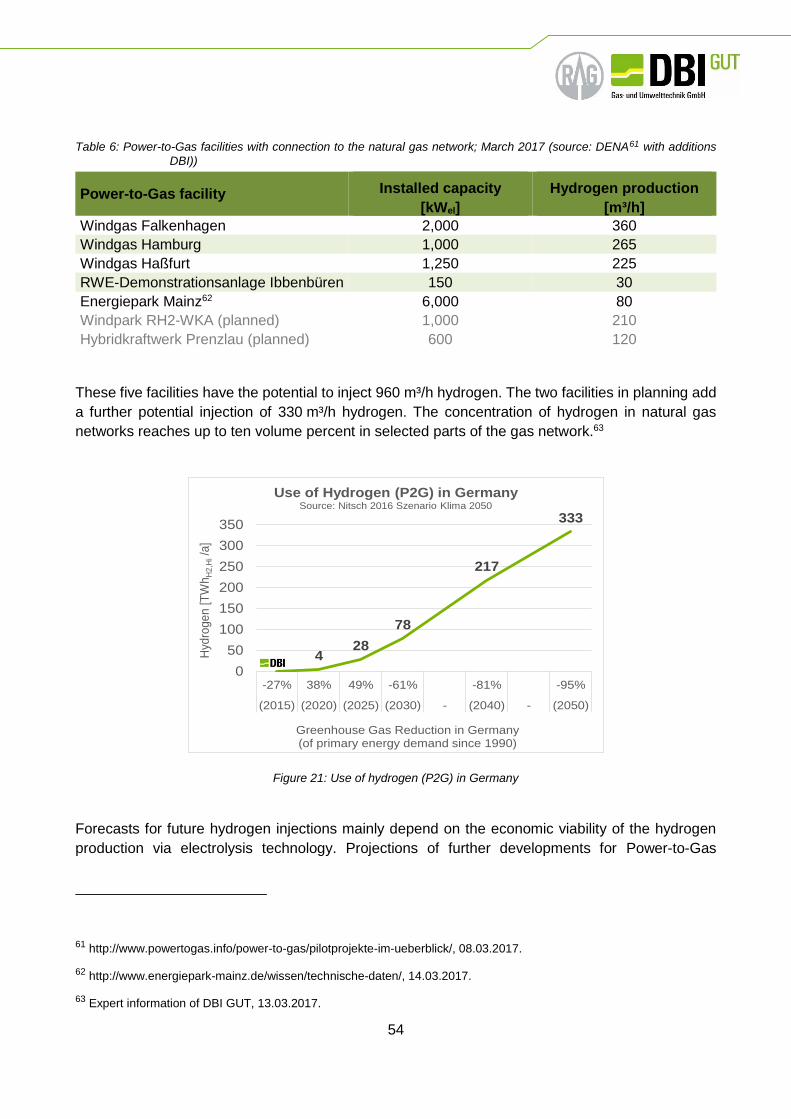
54
Table 6: Power-to-Gas facilities with connection to the natural gas network; March 2017 (source: DENA61 with additions
DBI))
Power-to-Gas facility Installed capacity
[kWel]
Hydrogen production
[m³/h]
Windgas Falkenhagen 2,000 360
Windgas Hamburg 1,000 265
Windgas Haßfurt 1,250 225
RWE-Demonstrationsanlage Ibbenbüren 150 30
Energiepark Mainz62 6,000 80
Windpark RH2-WKA (planned) 1,000 210
Hybridkraftwerk Prenzlau (planned) 600 120
These five facilities have the potential to inject 960 m³/h hydrogen. The two facilities in planning add
a further potential injection of 330 m³/h hydrogen. The concentration of hydrogen in natural gas
networks reaches up to ten volume percent in selected parts of the gas network.63
Figure 21: Use of hydrogen (P2G) in Germany
Forecasts for future hydrogen injections mainly depend on the economic viability of the hydrogen
production via electrolysis technology. Projections of further developments for Power-to-Gas
61 http://www.powertogas.info/power-to-gas/pilotprojekte-im-ueberblick/, 08.03.2017.
62 http://www.energiepark-mainz.de/wissen/technische-daten/, 14.03.2017.
63 Expert information of DBI GUT, 13.03.2017.
0 428
78
217
333
0
50
100
150
200
250
300
350
-27% 38% 49% -61% -81% -95%
(2015) (2020) (2025) (2030) - (2040) - (2050)
Hyd
roge
n [
TW
hH
2,H
i/a
]
Greenhouse Gas Reduction in Germany(of primary energy demand since 1990)
Use of Hydrogen (P2G) in GermanySource: Nitsch 2016 Szenario Klima 2050

55
installed capacity in 2050 amount to 40 GWel (110 TWhH2/a) according to the BMU Leitstudie.64 More
recent studies65 forecast up to 333 TWh/a renewable hydrogen (and methane) in 2050 (see Figure
21). The network development plan (NEP) for the electricity network predicts storage capacity needs
of 1-2 GWel in 2030.66 The NEP predictions only addresses electricity storage needs and do not
include the demand for renewable hydrogen to decarbonize further sectors, such as heating,
mobility, industrial material use.
Belgium
Hydrogen is currently not injected into the natural gas network. The Flemish power to gas cluster
analyses a possible demonstration project for the near future.67
United Kingdom
The United Kingdom has production sites for hydrogen via electrolysis, but none of them injects
hydrogen at present in the United Kingdom gas grid. Future developments will depend on the results
of the HyDeploy project and its influence on the gas safety regulations. For further information,
please see below 8.4.5.
Other application paths for hydrogen are already pursued: In 2030, a roadmap shows that the
national annual demand for hydrogen for fuel cell electric vehicles (FCEVs) will be 129,540 tons
produced by water electrolysis.68 These quantities will presumably not be transported in the gas grid,
since the FCEVs are running on pure hydrogen.
8.3 Underground gas storage strategies in neighbouring countries
Originally, UGS were built as a gas accumulation element covering imbalances in gas consumption
markets. Today UGS have developed into a complex gas infrastructure providing physical flexibility
to gas markets to deliver gas at a short notice according to market needs.
64 Szenario 2011A in BMU Leitstudie, Nitsch et al. „Langfristszenarien und Strategien für den Ausbau der erneuerbaren
Energien in Deutschland bei Berücksichtigung der Entwicklung in Europa und global“, 29.03.2012, S. 11,
http://www.fvee.de/fileadmin/publikationen/Politische_Papiere_anderer/12.03.29.BMU_Leitstudie2011/BMU_Lei
tstudie2011.pdf, 8.3.17.
65 Nitsch “Energiewende nach COP 21 – Aktuelle Szenarien der deutschen Energieversorgung“, 17.02.2016, page 62;
https://www.bee-ev.de/fileadmin/Publikationen/Studien/Joachim_Nitsch_Energiewende_nach_COP21_Langver
sion.pdf, 8.3.17. Own presumption, that 20% of biofuels are hydrogen.
66 Netzentwicklungsplan Strom 2030, Version 2017, 1st draft, page 5, https://www.netzentwicklungsplan.de/sites/
default/files/paragraphs-files/NEP_2030_1_Entwurf_Zahlen-Daten-Fakten_online.pdf, 14.03.2017.
67 Expert information of Synergrid/Eandis 09.03.2017 and WaterstofNet 10.03.2017.
68 http://www.ukh2mobility.co.uk/the-project/production-and-distribution/, 08.03.2017

56
Figure 22: UGS distribution in Europe69
At present, the European Union has a total working gas capacity of 98.7 bm3. The recently reported
plan foresees to add a working gas volume of 64.7 bm3 mainly in salt caverns (Germany, UK) and
additional extensions of existing sites69. An overview about the UGS distribution in Europe and the
technical working gas volume of UGS facilities of the neighbouring countries of Netherlands is shown
in Figure 22, Table 7 and
Table 8.
69 IGU (2015): Natural Gas Facts & Figures http://www.igu.org/sites/default/files/node-page-field_file/FactsFigures_4.pdf,
24.03.2017
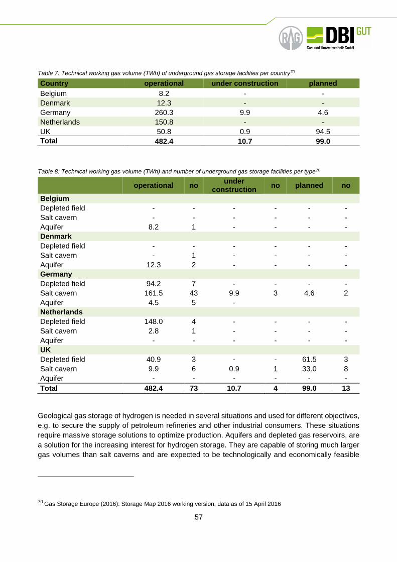
57
Table 7: Technical working gas volume (TWh) of underground gas storage facilities per country70
Table 8: Technical working gas volume (TWh) and number of underground gas storage facilities per type70
operational no under
construction no planned no
Belgium
Depleted field - - - - - -
Salt cavern - - - - - -
Aquifer 8.2 1 - - - -
Denmark
Depleted field - - - - - -
Salt cavern - 1 - - - -
Aquifer 12.3 2 - - - -
Germany
Depleted field 94.2 7 - - - -
Salt cavern 161.5 43 9.9 3 4.6 2
Aquifer 4.5 5 -
Netherlands
Depleted field 148.0 4 - - - -
Salt cavern 2.8 1 - - - -
Aquifer - - - - - -
UK
Depleted field 40.9 3 - - 61.5 3
Salt cavern 9.9 6 0.9 1 33.0 8
Aquifer - - - - - -
Total 482.4 73 10.7 4 99.0 13
Geological gas storage of hydrogen is needed in several situations and used for different objectives,
e.g. to secure the supply of petroleum refineries and other industrial consumers. These situations
require massive storage solutions to optimize production. Aquifers and depleted gas reservoirs, are
a solution for the increasing interest for hydrogen storage. They are capable of storing much larger
gas volumes than salt caverns and are expected to be technologically and economically feasible
70 Gas Storage Europe (2016): Storage Map 2016 working version, data as of 15 April 2016
Country operational under construction planned
Belgium 8.2 - -
Denmark 12.3 - -
Germany 260.3 9.9 4.6
Netherlands 150.8 - -
UK 50.8 0.9 94.5
Total 482.4 10.7 99.0

58
because of the long history of storing gases in porous media. However, the physico-chemical
behaviour of underground hydrogen storage is significantly different from traditional types of gas
storages in surface facilities. Salt caverns are frequently used to store natural gas. The two biggest
advantages of salt caverns are an extremely high gas tightness of the salt rock and the ability of fast
changes in operation mode (injection/production). In the United States, United Kingdom and
Germany (town gas), cavern storages are also used for storing hydrogen. An Overview of hydrogen
mixtures and pure hydrogen underground storage facilities are given in Table 9:
Table 9: Underground storage of hydrogen worldwide71,72
Type Gas (%)
p/T Volume
(m³) Capacity
(sm³) Depth
(m) Start-up Status
Germany
Ketzin Aquifer CO2
62 % H2 - - - 200-250 - closed
Kiel Salt
cavern 62 % H2 80-100 bar 32,000 - - -
operating with
natural gas
United Kingdom
Teesside Salt
cavern 95 % H2
3-4 % CO2 50 bar - 1.000.000 400 1959 operating
USA
Spindletop Salt
cavern 95 % H2 - - - - - operating
Clemens Dome
Salt cavern
95 % H2 70-135 bar 580,000 30.000.000 850 1980s operating
Moss Bluff Salt
cavern - - - - - - operating
France
Beynes Aquifer 50 % H2 - - 385.000.000 430 1956 - 1972
operating with
natural gas
Czech Republic
Lobodice Aquifer 50 % H2
25 % CH4
90 bar / 34°C
- - 430 1965 operating
Argentina
Diadema (Hychico)
Depleted gas
reservoir 10 % H2
10 bar / 50°C
- - 600 2009 -
Austria
Underground Sun Storage
Depleted gas
reservoir 10% H2
78 bar / 40 °C
1.150.000 1000 2015 - 2017 operating
71 Panfilov, M. (2016): Underground and pipeline hydrogen storage in Compendium of Hydrogen Energy, Volume 2:
hydrogen Storage, Transportation and Infrastructure, p. 91-115
72 Praxair: The application of Praxair, Inc., For a permit to create, operate and maintain an underground gas storage facility,
Praxair hydrogen storage lease, well No. 1, Moss Bluff field, Liberty County, Texas
59
Today, a number of industrial hydrogen underground storage applications are in operation. The
chemical industry is operating hydrogen salt caverns in Clemens and Moss Bluff in the U.S., as well
as in Teesside in the United Kingdom (for further information see chapter 7.7). In these particular
cases, the stored hydrogen is used as a product in the chemical industry and not as an energy
vector. Furthermore, hydrogen has successfully been stored in underground facilities in France,
Germany and Czech Republic, in the form of town gas: a gas mixture including a hydrogen content
of 40-60 %, carbon monoxide, methane and volatile hydrocarbons (for further information see
chapter 0).
The Hychico hydrogen plant, in Argentina, started operating in January 2009. It is located in the
outskirts of the city of Comodoro Rivadavia, Province of Chubut and is the first “Large scale clean
hydrogen production in Patagonia Argentina” pilot project. The plant has two hydrogen-producing
electrolysers. This hydrogen is mixed with natural gas and used as fuel. In addition, there is a high
pressure oxygen dispatch plant (220 bar) which supplies the local market73. Hychico took part in the
European Union program HyUnder with a hydrogen production plant of 120 Nm3/h (99,998 % purity),
a wind farm (6.3 MW), and an average annual capacity factor of 50 %. This constituted the first stage
of the Hychico program74.
Since 2016, Hychico started a pilot project to produce methane from hydrogen and carbon dioxide
by underground controlled methanogenesis. The efforts include the site biological characterization,
identification and optimization of operational and reservoir parameters.
In 2013 an Austrian consortium, initiated and managed by RAG, started the Underground Sun
Storage research campaign. In 2016 an in-situ field experiment with 10 % hydrogen admixture to
natural gas was done. From an integrity point of view no curtailment was observed. Further results
are to be published in 2017.
In 2017 RAG together with several partners started the Underground Sun Conversion research
campaign. The focus of this project is to enhance methanogenesis in depleted gas reservoirs by
injecting hydrogen and carbon dioxide. Field experiments are again the centrepiece of that project.
Further details under: www.underground-sun-conversion.at.
8.4 Safety regulations for hydrogen injection
This chapter gives an overview about (safety) regulations for hydrogen injection. On one hand, this
relates to the admissible hydrogen concentration in natural gas networks and on the other hand to
the design and operation of hydrogen injection facilities. Both questions are subject to national
regulations, since neither international nor European standards set definite rules. We will describe
73 S. Raballo, J. Llera, A. PÈrez, J. C. Bolcich (2010): Clean Hydrogen Production in Patagonia Argentina, 18th World
Hydrogen Energy Conference 2010 - WHEC 2010
74 A. Pérez1, E. Pérez, S. Dupraz, J. Bolcich (2016): Patagonia Wind - Hydrogen Project: Underground Storage and
Methanation, 21st World Hydrogen Energy Conference 2016. Zaragoza, Spain. 13-16th June, 2016

60
applicable standards and regulations on international level first, before addressing the national
situations in Belgium, Denmark, Germany, and United Kingdom.
International and European standards or rules
The gas quality for usage in the natural gas grid is standardised in Europe. The European Committee
for Standardization (CEN) developed a standard “Gas infrastructure - Quality of gas - Group H” (EN
16726:2015) which was published in 2015.75 Admissible hydrogen concentrations in natural gas
systems is covered separately in Annex E (informative). The CEN standard summarises “At present
it is not possible to specify a limiting hydrogen value which would generally be valid for all parts of
the European gas infrastructure and, as a consequence, it is recommended a case by case analysis.”
The standard EN 16723-1 (November 2016) for bio-methane injection also refers to the informative
Annex E of the above mentioned standard EN 16726:2015. The question of the admissible hydrogen
concentration therefore remains.
In addition to the CEN standard from 2015, a further document - a Common Business Practice -
touches the gas quality for cross-border transmission. EASEE-gas (European Association for the
Streamlining of Energy Exchange-gas) released in 2005 the Common Business Practice (CBP)
2005-001/02 “Harmonisation of Gas Qualities”.76 The CBP recommends natural gas quality
specifications, parameters and parameter ranges to streamline interoperability at cross border points
in Europe. Hydrogen concentration limits are not mentioned in concrete figures but “insignificant
levels of hydrogen” are tolerated.77 As the CBP has not been issued by an authorized body or
organisation, it is not legally binding for the transportation of natural gas, unless agreed upon under
private law agreements.
Neither CEN standards nor the CBP set definite limits for admissible hydrogen concentrations in
natural gas systems.
The ISO 13686 “Natural gas – quality designation” contains rather a general description of different
parameters than concrete parameters in the sense of thresholds, limits, or ranges. The ISO 13686
standard refers for gas quality parameters on an informal basis to the above-mentioned Common
Business Practice (CBP 2005-001/02).
75 https://standards.cen.eu/dyn/www/f?p=204:110:0::::FSP_PROJECT:38695&cs=1D1987DCC78FF8BF1 67938CA854
1ECA5, 08.03.2017.
76 CBP Common Business Practice 2005-01/02, 08.02.2005: Harmonisation of Natural Gas Quality. http://easee-
gas.eu/media/4085/cbp%202005-001-02%20_3.pdf, 07.03.2017.
77 CBP 2005-001/02 Harmonisation of Natural Gas Quality, p. 6. https://easee-gas.eu/download_file/DownloadFile/4/cbp-
2005-001-02-harmonisation-of-natural-gas-quality, 23.02.2017.

61
Further developments cannot be retrieved on European or international level.78 International or
European standardization has not yet determined thresholds for hydrogen concentration when
injected into the natural gas grid.
One exemption applies when a CNG fuelling station is directly connected to the gas grid. The
UN/ECE regulation No 110 requires “hydrogen shall be limited to two percent by volume when
cylinders are manufactured from a steel with an ultimate tensile strength exceeding 950 MPa.”79 This
limitation applies to CNG80 type 1 cylinders and implies that CNG fuelling stations, as well as the
supplying gas network are affected by the two percent hydrogen limitation.
Since the admissible hydrogen concentration cannot be determined by international or European
regulation, we need to focus on national regulations of Denmark, Germany, Belgium and the United
Kingdom. The restrictions are derived by literature review and expert interviews. We asked two
questions to experts who are familiar with the gas infrastructure and hydrogen admixture in the
respective countries:
1. Do you have regulations in Belgium for the admissible hydrogen concentration?
2. Do you have further regulations for operating hydrogen injection facilities in the natural gas
network?
Depending on the answers, we continued questioning in more detail. Please note, that the
concentration may be limited by gas quality parameters, e.g. Wobbe index, methane number. The
parameters vary between natural gas qualities from different origin (e.g. Russia, Norway, and
Netherlands) and can be determined by calculation. These restrictions are however not subject to
the following explanations. We concentrate here on explicit regulations of hydrogen and natural gas
blends. The Table 10 summarizes research results on thresholds for hydrogen concentrations in the
gas grid.
Table 10: Overview of national limitations for hydrogen in natural gas systems; March 2017.
78 See for EU https://ec.europa.eu/energy/en/topics/markets-and-consumers/wholesale-market/gas-quality-harmonisation
6.3.17.
79 Official Journal of the European Union L 120, 7.5.2011, page 37; http://eur-lex.europa.eu/LexUriServ/LexUriServ.do?
uri=OJ:L:2011:120:0001:0108:EN:PDF, 6.3.17.
80 CNG – compressed natural gas.
Country Limits of hydrogen concentration
Belgium <0.1 mol.-%; exemptions on case by case analysis possible.
Denmark Hydrogen admixture not allowed; exemptions on case by case analysis
possible.
Germany <10 vol.-% (2 vol.-% for CNG fuelling stations); higher concentrations
United Kingdom 0.1 vol.-%; exemptions on case by case analysis possible.

62
Denmark
An investigation on new acceptable EU limits for gas quality, performed in 2010, gives an overview
about the gas quality parameters of natural gas in Denmark. The Danish gas transmission operator
energinet.dk has gas quality specifications in addition to national gas quality requirements.
Admixture of hydrogen is currently not allowed in the Danish gas system. Exemptions from this
general rule are possible upon request. The Danish Safety Technology Authority (www.sik.dk) can
permit injecting hydrogen up to a certain percentage into specific distribution grid. Work is underway
to determine the technical limit of the Danish gas system.81
There are further regulations in place for operating hydrogen injection facilities in the natural gas
network. An operator would need to apply the Danish gas legislation (www.sik.dk), legislation from
the Danish working environment authority (www.at.dk) and the Danish emergency management
agency (www.brs.dk) regarding these kinds of facilities. The latter is probably only relevant if the
facility includes hydrogen production of hydrogen storage.82
Germany
National legislation does not limit the hydrogen concentration in the gas network in Germany. The
German Association of Gas and Water (DVGW) addresses technical questions around the gas
infrastructure and acts as regulatory body for regulations to ensure the safety of the gas network.
The standardization work of the DVGW is an industry driven initiative (self-regulation). The injection
of hydrogen is foreseen as long as the concentration remains below ten volume percent of the
transmission grit.83 The technical standards however acknowledge infrastructure elements and
appliances with lower tolerances, such as porous rock underground gas storages, turbines, vehicle
CNG cylinders type 1. The applicable threshold may therefore drop down to two or even one percent
hydrogen admixture if there are sensitive elements connected to the respective part of the gas grid.
The gas network operator sets the hydrogen limit for injection depending on the actual existing
downstream applications on a case-by-case analysis.
The DIN (German Institute for Standardization) established a threshold of up to two volume percent
hydrogen for the vehicle fuel CNG (compressed natural gas) in the standard DIN 51624. The DVGW
regulation and the DIN standard are not of rival nature, they supplement each other. If there is a
CNG fuelling stations connected to the respective part of the gas grid, the admissible hydrogen
concentration will not exceed two volume percent.
In addition to the aforementioned regulations of the DVGW and DIN regarding the gas quality, the
DVGW developed a technical standard for the injection of hydrogen in the gas network. This
81 The permit was given in the past. One project in Denmark exists where up to 2 % hydrogen is allowed in a distribution
grid. The hydrogen is leftover hydrogen from methanation of CO2. Expert information from energinet.dk,
10.03.2017.
82 Expert information from energinet.dk, 10.03.2017.
83 DVGW G 2060 page 25; DVGW G 262 page 17.
63
standard (DVGW G 265-3) applies to the designing, construction, testing, commissioning, and
operation of hydrogen injection facilities in gas networks. Its focus are security related requirements.
Belgium
The regulatory framework of the national gas association Synergrid for bio-methane injection limits
the hydrogen concentration in the transmission and distribution network to below 0.1 mol.-%.84 Any
request for higher hydrogen concentrations will be analysed case by case in accordance with EN
16726:2015 Annex E. This standard supersedes the national limit and opens the door for exemptions
(see 8.4.1).
According to the study ‘Power-go-Gas Roadmap for Flanders’, two percent by volume is currently
the maximum concentration to be allowed in gas grids.85 This cautious approach is derived from the
above-mentioned UN/ECE R110 limit of two percent by volume. These hydrogen values are not
official limits and represent neither the official view nor policies of the Belgium DSOs, TSOs nor of
the government.86
United Kingdom
The official regulatory authority - the Office for Gas and Electricity Markets (OFGEM) - issued Gas
Safety (Management) Regulations. The regulations currently limit the share of hydrogen to
0.1 mol.-%.87 This cautious approach was taken to protect the health and safety of domestic
customers and is due to insufficient knowledge about the influence of hydrogen admixture.
OFGEM is currently funding a large project (with GBP 6.8 m) to advance the knowledge about the
hydrogen tolerance of the gas network. The results of the HyDeploy project are expected by 2020.
This project, conducted by National Grid Gas Distribution Ltd. in cooperation with several other
partners, represents the first practical deployment of hydrogen into a live gas network in the United
Kingdom since 1977 (when the United Kingdom gas network was converted from town gas to natural
gas). The goal of the project is to demonstrate that natural gas containing levels of hydrogen beyond
those in the GS(M)R specification (General Safety (Management) Regulations) can be distributed
and utilized safely and efficiently in a representative section of the United Kingdom distribution
network.88 The work via HyDeploy intends to take a private network up to a maximum of 20 % by
84 Synergrid G5/42 „Technisch voorschrift Biomethaan“, March 2016, page 10f, http://www.synergrid.be/download.cf
m?fileId=G5_42_NL_v201603_VoorschriftInjectieBiomethaan.pdf, 10.03.17.
85 Thomas et al. „Power-go-Gas Roadmap for Flanders“, Final Report, October 2016, page 74, http://www.power-to-
gas.be/final-report, 6.3.17.
86 Expert information of Synergrid, 13.03.2017.
87 Health and Safety Executive „A guide to the Gas Safety (Management) Regulations 1996“, 2nd edition, 2007, page 49,
http://www.hse.gov.uk/pubns/priced/l80.pdf, 10.03.2017.
88 Project submission HyDeploy; https://www.ofgem.gov.uk/system/files/docs/2016/04/ng_ngn_hydeploy_isp.pdf, 7.3.17.

64
volume dependent on the exemption the consortium can achieve and the testing feedback. After this
project completes the consortium would look to extend the threshold onto the public gas network
based on the information gained during the project.89
89 Expert information of National Grid, 10.03.17.

65
Summary
Hydrogen storage within caverns or porous reservoirs is exercised in specific locations within Europe
and the US. But the large scale injection of hydrogen into the natural gas grid and as well as a higher
amount of hydrogen storage causes further challenges. In order to secure the save operation of UGS
the potential effects and damages caused by hydrogen within the cap rock, reservoir, borehole
completion and surface facilities have to be analysed. Summing up the collected knowledge of the
current report, the following Table 11 shows the feasibility issues of hydrogen injection into the
underground gas storages of the Netherlands.
Table 11: Summary of the feasibility of hydrogen injection into underground gas storages of the Netherlands
feasible
feasible but specific investigations recommended
insufficient knowledge further research needed
not feasible
0.5 % H2 10 % H2 100 % H2
Pore Cavern Pore Cavern Pore Cavern
Tightness and hydraulic integrity of the cap rock
Geochemical and microbiological reactions
be aware for energy
losses
Changes in transport mechanisms
dissolution
cushion gas
Technical integrity / steel alloys
Technical integrity / cementation
Technical integrity / elastomers
Surface equipment and operational effects
existing
facilities
existing
facilities
The injection of a hydrogen amount of up to 0.5 % into the Dutch underground gas storages is too
our knowledge, feasible for caverns as well as porous reservoirs, except for technical integrity of

66
steel alloys. For the borehole completion used in the Dutch underground gas storages specific
investigations need to be made in order to make sure integrity losses or damage caused by hydrogen
does not occur.
For a hydrogen content of up to 10 % specific investigations in areas of tightness and hydraulic
integrity of the cap rocks as well as changes in transport mechanisms are needed. Also research of
technical integrity of elastomers is recommended for both porous reservoirs, and cavern storages. It
should be kept in mind that the high maximum pressures of Dutch underground gas storages also
lead to a high partial hydrogen pressure. Furthermore research for the borehole completion and
surface facilities need to be done to guarantee the technical integrity and the save operation of the
specific UGS facility’s. Additionally, the chemical and microbiological potential of the Dutch porous
UGS formations has to be investigated.
For the adjustment of the natural gas storages into pure hydrogen cavern and porous UGS the
surface equipment has to be replaced and redesigned for the use of hydrogen. Similar to the
hydrogen content of 10 % the steel alloys of the existing borehole completions and the geochemical
and microbiological reactions need to be investigated. For the tightness and hydraulic integrity of the
cap rock, the changes in transport mechanisms, the technical integrity of the cementation and
elastomers, specific investigations for every Dutch underground gas storage are recommended.

This is a publication of
Netherlands Enterprise Agency
Prinses Beatrixlaan 2 | 2595 AL Den Haag
Postbus 93144 | 2509 AC Den Haag
T +31 (0) 88 042 42 42
www.rvo.nl
This publication was commissioned by the ministry of Economic Affairs.
© Netherlands Enterprise Agency | July 2017
Publication number: RVO-079-1701/RP-DUZA
NL Enterprise Agency is a department of the Dutch ministry of Economic Affairs that
implements government policy for Agricultural, sustainability, innovation, and
international business and cooperation. NL Enterprise Agency is the contact point
for businesses, educational institutions and government bodies for information and
advice, financing, networking and regulatory matters.
Netherlands Enterprise Agency is part of the Ministry of Economic Affairs.


