Embed Size (px)
Citation preview

The Effects of Crosswind Flight on Rotor Harmonic Noise Radiation
Eric Greenwood⇤Aeroacoustics Branch
NASA Langley Research CenterHampton, VA
Ben W. Sim†
US Army Aviation Development Directorate – AFDDAviation & Missile Research, Development & Engineering Center
Research, Development and Engineering CommandMoffett Field, CA
ABSTRACTIn order to develop recommendations for procedures for helicopter source noise characterization, the effects ofcrosswinds on main rotor harmonic noise radiation are assessed using a model of the Bell 430 helicopter. Crosswindsare found to have a significant effect on Blade-Vortex Interaction (BVI) noise radiation when the helicopter is trimmedwith the fuselage oriented along the inertial flight path. However, the magnitude of BVI noise remains unchanged whenthe pilot orients the fuselage along the aerodynamic velocity vector, “crabbing” for zero aerodynamic sideslip. Theeffects of wind gradients on BVI noise are also investigated and found to be smaller in the crosswind direction than inthe headwind direction. The effects of crosswinds on lower harmonic noise sources at higher flight speeds are alsoassessed. In all cases, the directivity of radiated noise is somewhat changed by the crosswind. The model predictionsagree well with flight test data for the Bell 430 helicopter captured under various wind conditions. The results of thisinvestigation would suggest that flight paths for future acoustic flight testing are best aligned across the prevailing winddirection to minimize the effects of winds on noise measurements when wind cannot otherwise be avoided.
NOTATION
DF Fuselage parasite drag.fe Effective flat plate drag area of the fuselage.g Gravitational acceleration.h Altitude above ground.H Rotor “hub” force.R Rotor radius.t Time.V Rotor free stream velocity.VGND Helicopter ground-track (inertial) velocity.VIAS Helicopter indicated airspeed.w Wind velocity.W Helicopter weight.
aF Fuselage angle of attack.aT PP Rotor tip-path-plane angle of attack.bF Fuselage sideslip angle.bI Angle between free stream and inertial velocities.g Flight path angle.r Air density.µ Main rotor advance ratio.q Elevation angle relative to the horizon.y Azimuth angle relative to flight path.x Linear wind gradient magnitude.W Rotor rotational speed.
⇤Research Aerospace Engineer, [email protected]†Research Scientist, [email protected]
Presented at the American Helicopter Society 69th Annual Forum, Phoenix, AZ, May
21-23, 2013. This is a work of the U.S. Government and is not subject to copyright
protection in the U.S.
INTRODUCTIONAcoustic mission planning tools, such as the Rotorcraft NoiseModel (RNM), (Refs. 1–3) develop and apply empirical modelsof helicopter external noise radiation to assess the annoyanceor detectability of helicopter flight operations. Empirical noisemodels are used because they are able to provide accuratenoise estimates quickly and at a relatively low computationalcost. However, the process of collecting the acoustic data fromwhich these models are constructed is complex. Typically,a specific model of helicopter is characterized by repeatedflights of the helicopter over a ground-based linear array ofmicrophones. During each flight, the helicopter remains in asteady flight condition following a straight-line flight path overthe microphone array, shown in Figure 1.
As the helicopter passes over the microphone array, acousticmeasurements are captured across a range of directivity angleswith respect to single point on the helicopter, typically locatedat the main rotor hub. The method assumes that the helicopter’snoise radiation characteristics can be represented in the far-field as a compact source and that this acoustic source doesnot vary over time because the helicopter’s flight conditionis nominally steady. Under these assumptions, ground-basednoise measurements are normalized to a fixed distance awayfrom the assumed compact source, accounting for sphericalspreading and atmospheric absorption losses. This processforms an acoustic hemisphere representing the noise radiationcharacteristics of the helicopter for a particular flight condition.These hemispheres are frequently represented using a Lambertprojection, shown in Figure 2 with coordinates aligned withthe flight path and affixed to the horizon plane. The Lambertprojection maps data from the surface of the hemisphere toa conic section which is unrolled for display in two dimen-
1
https://ntrs.nasa.gov/search.jsp?R=20130013862 2018-06-22T08:47:40+00:00Z

Fig. 1. Diagram of the process of building an empiricalsource noise hemisphere for a straight-line steady flightcondition. Red points represent ground-based micro-phone locations and blue points the corresponding loca-tions on the acoustic hemisphere surface.
sions. (Ref. 4) This projection is used because it minimizes thedistortion in area of features when they are displayed in two di-mensions, more accurately representing the relative importantof features to the overall noise radiation of the helicopter. Theacoustic hemisphere construction process is repeated for nu-merous flight conditions, typically varying airspeed and flightpath angle, in order to develop a database of the helicopternoise radiation characteristics as a function of the steady oper-ating condition. The result is a model of the helicopter noiseradiation characteristics which can be applied to assess theacoustic characteristics of a proposed mission or flight plan.
During flight testing, low wind conditions are sought out,but it is rare that zero wind conditions can be obtained. Flightpaths for source noise characterization measurements are typ-ically aligned along the prevailing headwind direction, as iscommon in vehicle performance testing. However, winds ori-ented along the direction of propagation are known to havea strong effect on the propagation of sound from the sourceto the observers. (Refs. 5–7) On the other hand, the effects ofwind normal to the propagation path are known to be relativelysmall, (Refs. 8, 9) inducing small shifts in the observed direc-tivity pattern. The relatively small effects of crosswinds areoften neglected in propagation codes.
In addition to the effects on propagation, headwinds areknown to affect the source noise characteristics of rotorcraft inflight. Near the ground, wind speeds tend to increase with alti-tude forming a wind gradient. Previous theoretical and experi-mental investigation has shown that during descending flightconditions, such as those where Blade-Vortex Interaction (BVI)noise occurs, the wind gradient induces a longitudinal accelera-tion on the helicopter as it flies at a constant airspeed. (Ref. 10)This longitudinal acceleration has the effect of changing thetrim state of the vehicle, and hence the tip-path-plane angleof attack. This change in the tip-path-plane angle of attack isequivalent to a change in the flight path angle of the vehicleand has a strong effect on the radiated BVI noise. The effects
RetreatingSide
AdvancingSide
Front
Rear
Flight Path
θUnder
= -90°
ψ θ= 0° = 0°
ψ θ= 180° = 0°
RetreatingSide
AdvancingSide
Under= -90°θ
Frontψ θ= 180° = 0°
ψ= 90°θ= 0°
ψ= 270°θ= 0°
Rearψ θ= 0° = 0°Rearψ θ= 0° = 0°
Flight Path
Fig. 2. Lambert projection of an acoustic hemisphere.of crosswinds on the source noise radiation characteristics havenot been thoroughly investigated.
It is the objective of this paper to assess the effects of cross-wind flight on the noise generation of helicopter main rotorsto first-order, using a semi-empirical model of the Bell 430helicopter. These results are compared to noise measurementsof the Bell 430 during no wind and crosswind flight conditions.Recommendations are then made for new flight testing proce-dures for routine source noise characterization with the aim ofreducing the impact of winds on the measurements.
THEORY
The model applied in this paper to assess the effects of cross-wind flight on main rotor harmonic noise radiation is an ex-tension of a previously developed semi-empirical model forestimating helicopter main rotor aerodynamics and acoustics.(Refs. 11,12) The model employs the Ffowcs Williams – Hawk-ings (FW–H) acoustic analogy method. (Ref. 13) Aerodynamicinputs are provided for each condition using a prescribed wakemodel combined with an incompressible indicial unsteady aero-dynamics model. The FW–H equation is solved numericallyusing Farassat Formulation 1A. (Ref. 14) Acoustic sources offthe blade surfaces, such as those causing High Speed Impul-sive (HSI) noise, are neglected for the moderate advancing tip
2

Mach number range examined in this paper. Thickness noise isdirectly computed from the blade geometry and rotor operatingcondition. Loading noise, both lower harmonic and BVI noise,is determined from an assumed aerodynamic model adaptedto measured data using the Fundamental Rotorcraft AcousticModeling from Experiments (FRAME) technique. (Ref. 15)Since FRAME is based on non-dimensional parameters, mea-sured data can come from multiple sources; in this paper datafrom the 1/7
th scale Operational Loads Survey rotor tested inthe DNW windtunnel (Ref. 16) is combined with flight test datafrom the Bell 430 helicopter collected during a NASA/BellHelicopter/US Army flight test at Eglin Air Force Base in June2011. (Ref. 17)
The wake model is based on the Beddoes prescribed wake,(Refs. 18, 19) but is modified to include additional dependentparameters adjusted by FRAME in order to adapt the modelto existing empirical data for a particular rotor configuration.These additional parameters describe the non-uniform longi-tudinal and lateral inflow variations across the rotor disk, theinitial vortex core size and its rate of growth (Ref. 20), the tipvortex rollup radius, the rate of wake contraction (Ref. 21), andthe harmonic variation of vortex circulation strength about therotor azimuth. The velocities induced by the wake onto therotor blades are then corrected using the Beddoes-Leishmanindicial aerodynamics model (Refs. 22, 23) to account for thedelayed response of the shed wake on the rapidly changingaerodynamic loading felt by the blade elements. This is sim-ilar to the analytical modeling used in previous theoreticalresearch into BVI noise, (Ref. 24) but with additional physi-cally meaningful wake distortion terms to allow the model tobe accurately fitted to the measured acoustic data. The cor-responding rotor flap response is solved numerically under arigid blade assumption.
This model is extended to crosswind flight conditions byincorporating a full six degree of freedom force and momentbalance to establish the free flight trim condition of the entirehelicopter during steady sideslipped flight. The mean mainrotor forces and moments are calculated from blade elementtheory using the FRAME prescribed wake to compute theinduced velocities; the tail rotor forces are computed under theassumption of uniform inflow with the tail rotor tip-path-planeangle of attack assumed equal to the fuselage sideslip angle.A non-linear least-squares numerical solver is used to find themain rotor cyclic and collective blade pitch, tail rotor collectiveblade pitch, and fuselage roll and pitch angles required tobalance all forces and moments for the entire helicopter insteady flight.
An important consideration in this model is the effect ofchanging wind direction on the fuselage aerodynamic char-acteristics. Empirical data describing the fuselage moment,drag, lift, and side forces as a function of angle of attack andangle of sideslip are used in this model. The fuselage of theBell 430 helicopter investigated in this paper was derived fromthat of the Bell 222 helicopter. Detailed aerodynamic data wascollected for a full scale Bell 222 fuselage, including empen-nage, in the NASA Ames 40’x80’ wind tunnel and is describedby Squires in Reference 25. Of particular importance is the
!25 !20 !15 !10 !5 0 5 10 15 20 2510
15
20
25
30
35
40
Sideslip Angle, deg.
Eff
ect
ive
Fla
t P
late
Dra
g A
rea
, ft2
Bell 430 (Scaled)
Bell 222
Fig. 3. Fuselage drag variation with sideslip angle for theBell 430 derived from full scale measurements of the Bell222 helicopter in the Ames 40’x80’ wind tunnel. (Ref. 25)
change in fuselage drag due to a change in fuselage sideslipangle, as this strongly influences the rotor’s tip-path-plane an-gle of attack with respect to the free stream velocity, and henceBVI noise. Following Schmitz, (Ref. 26) the angle of attack ofthe tip-path-plane resulting from an “X-force” balance in theaerodynamic axis system can be expressed to first order as:
aT PP ' �DF �HW
� g � 1g
����dVGND
dt
����x
(1)
where the fuselage drag is represented by:
DF =12
rV 2 fe(aF ,bF) (2)
The Bell 430 fuselage has a slightly higher drag than thatof the Bell 222 at zero sideslip, but extensive data are not avail-able; instead, the comprehensive Bell 222 fuselage aerodynam-ics data are uniformly scaled up to values more representativeof the Bell 430 for use in this paper. Figure 3 shows the scaled-up variation in the effective flat plate drag area as a functionof fuselage sideslip angle; as the sideslip angle of the fuselageincreases beyond 5�, a significant increase in the effective flatplate drag area of the fuselage is observed.
There are numerous trim solutions for steady flight in thepresence of a crosswind. In this paper, two distinct trim condi-tions are considered and are shown Figure 4. In one, the pilotflies the helicopter with the fuselage aligned in the inertial flightpath direction at the airspeed indicated by the non-swivelingpitot probe along the flight path direction. In this trim con-dition, the crosswind component of the wind velocity resultsin an aerodynamic sideslip angle of the fuselage, bF . Thefuselage produces a drag force, DF , in the same direction asthe free stream velocity, V . In addition, a fuselage side force,YF is generated normal to the free stream velocity vector, dueto the sideslip angle of the fuselage. The pilot compensatesfor this side force by tilting the helicopter at a slight roll angle.
3

β
Y
DF
F
F
V = VIASV
wβ=0
Y=0
DF
F
F
V = VIAS V
w
GNDGND
Fig. 4. Top view schematic of helicopter fuselage velocitiesand forces under crosswind conditions for a) sideslippedflight and b) “crabbed” flight.
Equation 3 describes the increase in main rotor advance ratioseen by the rotor caused by the introduction of the crosswindduring sideslipped flight. Main rotor BVI noise is a strongfunction of advance ratio; however, for realistic indicated air-speeds and wind velocities, the change in the advance ratiodue to the crosswind is slight. For example, the introductionof a 15 knot crosswind will cause an increase in the advanceratio by about 1.5% over the no wind condition when flying 80knots indicated airspeed in sideslipped flight.
Dµ =
qV 2
IND +w2 �VIND
WR(3)
In the second trim condition, the pilot flies with the heli-copter fuselage “crabbed” to align with the free stream velocityvector resulting in zero aerodynamic sideslip of the fuselage.The fixed pitot probe now indicates the free stream velocity ofthe aircraft, resulting in the same main rotor advance ratio asthe no wind condition. Because the fuselage is laterally sym-metric, the fuselage side force, YF , approaches zero in this trimcondition and the fuselage drag force reaches a minimum. Un-der both trim conditions, the crosswind skews the free streamvelocity relative to the initial flight path by an angle bI , suchthat:
sinbI =wV
(4)
Flying sideslipped in a crosswind could have a significantimpact on the rotor angle of attack, depending on the airspeedof the helicopter and the magnitude of the wind. Figure 5 plotsthe fuselage aerodynamic sideslip angle and the change in thedrag-to-weight ratio relative to flight in no wind conditions forthe Bell 430 helicopter in sideslipped flight at various airspeedsand crosswind magnitudes. From Equation 1, it is clear that thedrag-to-weight ratio, D f /W , has a strong effect on the angle of
40 60 80 100 120 1400
10
20
30
40
Sid
esl
ip A
ng
le !
F,
de
g.
40 60 80 100 120 1400
0.01
0.02
0.03
0.04
0.05
0.06
Indicated Airspeed, knots
Ch
an
ge
in D
f / W
du
e t
o C
ross
win
d
10 knots15 knots20 knots
Fig. 5. Change in sideslip angle, bF , and drag-to-weightratio, D f /W , as a function of airspeed, VIAS, due to cross-winds of different magnitudes during sideslipped flight.
attack of the main rotor tip-path-plane with respect to the freestream velocity, which could result in significant changes inthe magnitude of BVI noise. At low flight speeds, the fuselagesideslip angle will be high; however, because the free streamvelocity is low, fuselage drag forces are small. At high flightspeeds, the fuselage drag forces are high but the sideslip angleis low; at low sideslip angles, the fuselage drag characteristicsare relatively insensitive to small changes in the sideslip angle,as can be seen in Figure 3. However, at moderate airspeeds,the fuselage sideslip will result in a significant change in thedrag-to-weight ratio of the helicopter, resulting in a largerchange in the tip-path-plane angle of attack relative to no windconditions.
Wind Gradients In practice, the wind speed is not con-stant during a descending flight condition; the wind speedapproaches zero near the ground and increases with increasingaltitude. For a helicopter descending at a constant airspeedin a varying headwind, this results in an acceleration in theinertial frame, changing the trim of the helicopter. For exam-ple, assuming a linear wind gradient, w(h) = x ·h, the inertialacceleration of a descending helicopter is:
����dVGND
dt
����x=
dVGND
dt=V x sing (5)
To first order, this can be related to the change in the tip-path-plane angle of attack through Equation 1, i.e.
DaT PP '�V x
gsing (6)
4

The effect of a crosswind gradient on the trim of the heli-copter depends on the piloting technique. When the pilot flieswith the fuselage aligned with the inertial flight path direction,the indicated airspeed is not affected by the wind blowingacross the flight path. Consequently, the helicopter does notaccelerate in the inertial frame, although there is a gradualchange in the magnitude and direction of the wind seen bythe rotor. As the helicopter approaches the ground, the flightcondition becomes more like that of the zero wind case.
When the pilot “crabs” the fuselage such that the fuselageis aligned with the free stream velocity (i.e. zero sideslip), theindicated airspeed reflects the magnitude of the free streamvelocity and is somewhat affected by the crosswind. As thepilot maintains a constant indicated airspeed, the helicopterwill accelerate along the flight path direction due to the chang-ing crosswind magnitude. For a crosswinds less than the freestream velocity, the resulting acceleration along the flight pathdirection is:
dVGND
dt=� wp
V 2 �w2
dwdt
(7)
This acceleration may be resolved along the free streamvelocity direction, resulting in:
����dVGND
dt
����x=�w
Vdwdt
(8)
For a linear wind gradient, this results in a non-constantchange in the tip-path-plane angle of attack of:
DaT PP '�wV
V x
gsing =�wx
gsing (9)
Under realistic flight conditions, where the crosswind mag-nitude is much smaller than the free stream velocity, this indi-cates that the change in the longitudinal trim of the helicopterdue to a wind gradient will also be much less for the crosswindcase than for a headwind or tailwind.
EFFECTS OF CROSSWINDS ONMEASURED DATA
During the Bell 430 flight test at Eglin AFB, noise measure-ments were captured for several test points under a range ofwind conditions; these data were used to construct acoustichemispheres for use in acoustic mission planning tools such asRNM. Figure 6a shows the Lambert projection of the Blade-Vortex Interaction Sound Pressure Level (BVISPL) contoursfor the Bell 430 on the surface of a hemisphere set six ro-tor diameters away from hub during a steady 80 KIAS, -7.5�descent flight condition with near zero winds. In this paper,the BVISPL metric is defined as the unweighted sum of allnoise from the 6th to the 40th harmonics of the main rotorblade passing frequency. High levels of BVI noise are radiatedahead of and below the helicopter during this descending flightcondition.
During the test program, this flight condition was repeatedin the presence of a 11 knot crosswind coming from the ad-vancing side of the flight path. Figure 6b shows the measured
BVISPL hemisphere for the Bell 430 helicopter captured dur-ing an 80 KIAS, -7.5� flight path angle condition in the pres-ence of a steady crosswind of approximately 11 knots at flightaltitude blowing nearly orthogonal to the flight track fromthe advancing side. This results in a skew angle between theinertial flight path and the aerodynamic velocity seen by therotor, bI , of about 8�. Inflight instrumentation measured theaerodynamic sideslip of the fuselage throughout the run; formost of the descent, the pilot kept the fuselage “crabbed” withlow sideslip angles not exceeding 5�. However, as the vehicleapproached the ground near the end of the descent, the sideslipangle tended to increase as the pilot aligned the fuselage withthe flight path—by this time, the helicopter had passed themicrophone array and the rear portion of the hemisphere wasmeasured where lower levels of rotor harmonic noise are radi-ated. In comparison to the data collected for the same conditionin near-zero winds (Fig. 6a), there is little change in the BVInoise radiation except that the “directivity” has been yawedtowards the advancing side. Unfortunately, measured data wasnot collected for this flight condition at higher sideslip angles.
Data were also collected for higher speed level flight condi-tions, where no significant BVI noise occurs but higher levelsof lower harmonic noise are radiated. Figure 7a shows theOverAll Sound Pressure Level (OASPL) hemispheres capturedfor the helicopter in a 130 KIAS level flight condition in asteady 4 knot tailwind. Noise is radiated ahead of the heli-copter near the plane of the rotor and towards the advancingside.
The same condition was flown in a 11 knot crosswind fromthe advancing side of the flight path. The measured acoustichemisphere OASPL contours are shown in Figure 7b. Onceagain, the pilot flew with the fuselage oriented for low sideslip;the measured sideslip angle was generally below 3� throughoutthe run. However, the skew angle between the inertial flightpath and the aerodynamic velocity, bI , is only 6� because of thehigher flight speed of the helicopter. The change in noise radia-tion relative to the hemisphere for low wind conditions, Figure7a, is slight and well within normal measurement variability.
BELL 430 MODEL VALIDATION
The BVISPL contours predicted by the semi-empiricalFRAME model of the Bell 430 helicopter are shown for the80 KIAS, -7.5� flight path angle (FPA) condition with no windin Figure 8a. The levels and directivity of BVI noise com-pare well with the measured data for the same flight conditionshown previously in Figure 6a. The FRAME model is appli-cable over a range of flight conditions. Figure 9 compares themodel predicted results to BVI noise radiated directly aheadof the helicopter and 30� below the horizon across a range offlight path angles to the measured BVISPL values; the modelagrees well with the measured data during the steeper descentconditions where BVI dominates the BVISPL metric. At theshallower 0�and 3� flight path angles, the measured valuesexceed the prediction; note that the tail rotor noise is not mod-eled in the prediction but is included in the measured data.The tail rotor contributes significantly to noise in the BVISPL
5

50
55
60
65
70
75
80
85
90
95
100
0o
270 o
180
o 90
o
0 o
!90 o
!60 o
!30 o
0 o
(a) No wind.
50
55
60
65
70
75
80
85
90
95
100
0o
270 o
180
o
90o
0 o
!90 o
!60 o
!30 o
0 o
(b) 11 knot crosswind from the advancing side.
Fig. 6. Measured BVI noise hemispheres for 80 KIAS, -7.5� FPA flight condition, dB BVISPL
50
55
60
65
70
75
80
85
90
95
100
0o
270 o
180
o
90o
0 o
!90 o
!60 o
!30 o
0 o
(a) 4 knot tailwind.
50
55
60
65
70
75
80
85
90
95
100
0o
270 o
180
o 90
o
0 o
!90 o
!60 o
!30 o
0 o
(b) “Crabbed” in 11 knot crosswind from the advancing side.
Fig. 7. Measured noise hemispheres for 130 KIAS, level flight, dB OASPL.
frequency range because the tail rotor blade passing frequencyis about three times higher than that of the main rotor.
The model can be applied to look at the effects of cross-winds on noise radiation. Figure 8b shows the BVISPL con-tours for the helicopter in the same descending flight condi-tions, but with a steady 15 knot crosswind from the advancingside of the helicopter. The helicopter has been trimmed to“crab” the fuselage. The BVI noise radiation is unchanged inmagnitude, but now radiates more towards the advancing sideof the flight path, as was observed in the measured data for“crabbed” flight in crosswinds shown in Figure 6b.
In addition to BVI, the model can be applied to look atlower harmonic loading and thickness noise. Figure 10a shows
the OASPL contours predicted by the main rotor noise modeltrimmed for the Bell 430 in 130 KIAS level flight in no windconditions. The model output exhibits fairly good agreementwith the measured noise hemisphere shown in Figure 7a.
Figure 10b shows the same flight condition trimmed withthe fuselage “crabbed” for zero sideslip in the presence of asteady 15 knot wind from the advancing side of the flight path.Very little change in noise radiation is observed; there is aslight shift in the directivity 7� to towards the advancing side.This is similar to the effect of the crosswind on the measureddata for 130 KIAS flight that was shown in Figure 7b.
6

50
55
60
65
70
75
80
85
90
95
100
0o
270 o
180
o
90o
0 o
!90 o
!60 o
!30 o
0 o
(a) No wind.
50
55
60
65
70
75
80
85
90
95
100
0o
270 o
180
o
90o
0 o
!90 o
!60 o
!30 o
0 o
(b) “Crabbed” in 15 knot crosswind from the advancing side.
50
55
60
65
70
75
80
85
90
95
100
0o
270 o
180
o
90o
0 o
!90 o
!60 o
!30 o
0 o
(c) Sideslipped in 15 knot crosswind from the advancing side.
50
55
60
65
70
75
80
85
90
95
100
0o
270 o
180
o
90o
0 o
!90 o
!60 o
!30 o
0 o
(d) “Crabbed” in 15 knot crosswind from the retreating side.
50
55
60
65
70
75
80
85
90
95
100
0o
270 o
180
o
90o
0 o
!90 o
!60 o
!30 o
0 o
(e) Sideslipped in 15 knot crosswind from the retreating side.
Fig. 8. Predicted BVI noise hemispheres for 80 KIAS, -7.5� FPA flight, dB BVISPL.
7

RESULTS AND DISCUSSION
Effects of Piloting Technique and Wind Direction
In addition to estimating the noise radiation in low wind and“crabbed” crosswind flight, the model can be trimmed to asideslipped flight condition to examine the effect of pilotingtechnique on crosswind noise radiation. Figure 8c shows thehorizon-fixed noise hemisphere for the same 80 KIAS, -7.5�FPA flight condition (Fig. 8a) where the pilot has trimmedthe fuselage to align with the flight path in the presence ofa steady 15 knot crosswind coming from the advancing sideof the flight path. The presence of the crosswind causes thefuselage to operate in a 10� aerodynamic sideslip, increasingthe drag force by about 15% over the “crabbed” condition. Inaddition, a small lateral side force towards the advancing sideis generated. The change in fuselage drag forces causes therotor to tilt farther forward and towards the advancing sidethan in the no wind condition. The change in rotor trim resultsin a decrease in the tip-path-plane angle of attack by about2�. This causes in a decrease in BVI noise relative to no windconditions, with the peak BVISPL about 11 dB lower than thatof either the no wind (Fig. 8a) or “crabbed” (Fig. 8b) flightconditions. A reduction in noise levels is observed because thehighest BVI noise levels are observed in no wind conditions ata -7.5� flight path angle for the Bell 430 at 80 KIAS (Fig. 9).For a steeper descent, the decrease in tip-path-plane angle ofattack due to sideslipped flight could result in an increase inBVI noise.
In addition to a change in the tip-path-plane angle of attack,the increase in lateral side force causes the rotor tip-path-planeto roll 5� towards the advancing side along the aerodynamicfree stream velocity vector—this has little impact on the noisegeneration, but does cause the directivity of the radiated noiseto roll slightly towards the advancing side along with the tip-path-plane. Lastly, because the directivity of the radiated noiseis determined by the motion of the rotor with respect to themedium, irrespective of the inertial flight path of the vehicle,the noise radiation is yawed along with the free stream velocityvector towards the advancing side of the flight-path orientedhemisphere. This directivity shift is similar to that observedfor “crabbed” flight, shown previously in Figure 8b.
Figure 8d shows the acoustic hemisphere contours predictedby the model for the same flight condition where the pilot has“crabbed” the fuselage in response to a steady 15 knot cross-wind now coming from the retreating side. The aerodynamicflight condition is indistinguishable from the flight conditionin no wind conditions (Fig. 8a), but is now shifted towards theretreating side because of the change in the crosswind direction.Likewise, the effects of sideslipped flight in a crosswind fromthe retreating side, shown Figure 8e, are similar to those dueto sideslipped flight due to winds from the advancing side (Fig.8c). The sideslip caused by the wind from the retreating sidecauses a nearly identical decrease in the main rotor-tip-pathplane angle of attack as was caused by the wind from the ad-vancing side, however the rotor is now rolled further towardsthe retreating side. Of course, the noise radiation pattern is
0 1.5 3 4.5 6 7.5 975
80
85
90
95
100
Flight Path Angle, deg.
BV
ISP
L, dB
Predicted
Measured
Fig. 9. Comparison of measured and predicted BVISPL at180� azimuth, -30� elevation at 80 KIAS for various flightpath angles.
also yawed towards the retreating side, as was also observedfor “crabbed” flight in the same winds.
In all cases, the introduction of the crosswind causes a shiftin the directivity of radiated noise towards the incoming winddirection. During sideslipped flight, when the pilot keeps thefuselage aligned with the inertial flight path, the increase indrag results in significant changes in BVI noise. However,when the pilot “crabs” the fuselage for zero sideslip, the BVInoise state is unchanged. Therefore, it seems favorable to flythe helicopter in a “crabbed” trim condition to minimize theimpact of winds on the acoustic state of the vehicle duringnoise characterization measurements.
Effects of Crosswinds at Different Airspeeds
The effect of the crosswinds on the trim state of the rotor willbe strongly dependent on the flight speed of the vehicle. Atlower flight speeds, the same crosswind will cause a greaterdifference in orientation of aerodynamic and inertial velocityvectors of the rotor; conversely, at lower flight speeds thefuselage aerodynamic forces are smaller and their effects onthe trim of the helicopter generally reduced. Figure 11a showsan acoustic BVISPL hemisphere for a slower 50 KIAS -7.5�FPA flight condition without wind. As would be expected, theBVI noise levels are somewhat reduced from the higher speedflight condition. The change in rotor advance ratio has alsocause the predominate BVI to be radiated more towards theretreating side of the rotor than for the higher speed case.
Figure 11e shows the acoustic hemisphere for the corre-sponding flight condition in a 15 knot crosswind from theretreating side where the fuselage is oriented along the flightpath direction. This results in a fuselage sideslip angle of about15�. There is a small reduction of about 2 dB in the peak BVI
8

50
55
60
65
70
75
80
85
90
95
100
0o
270 o
180
o
90o
0 o
!90 o
!60 o
!30 o
0 o
(a) No wind.
50
55
60
65
70
75
80
85
90
95
100
0o
270 o
180
o
90o
0 o
!90 o
!60 o
!30 o
0 o
(b) “Crabbed” in 15 knot crosswind from the advancing side.
50
55
60
65
70
75
80
85
90
95
100
0o
270 o
180
o
90o
0 o
!90 o
!60 o
!30 o
0 o
(c) Sideslipped in 15 knot crosswind from the advancing side.
Fig. 10. Predicted overall noise hemispheres for 130 KIAS level flight, dB OASPL.
noise level relative to no wind conditions caused by a reductionin the tip-path-plane angle of attack by about 1�. Figure 11cshows the sideslipped condition with the crosswind approach-ing from the advancing side of the flight path, with a similarreduction in BVI noise levels. In both cases, the directivity isyawed with respect to the flight path due to the crosswind.
Figures 11d and 11b show the effects of the 15 knot cross-wind from the retreating and advance sides, respectively, forthe helicopter when the fuselage is “crabbed” for zero sideslip.As in the higher speed case, the only significant change in radi-ated noise is a shift in the directivity following the change inthe aerodynamic velocity direction with respect to the inertialflight path direction.
In higher speed level flight conditions, significant BVI doesnot occur and the lower harmonic noise sources are most sig-nificant. Figure 10c shows the OASPL contours for the 130KIAS level flight condition in a 15 knot crosswind blowingfrom the advancing side of the flight path, where the pilot has
aligned the fuselage in the flight path direction inducing a 4�aerodynamic sideslip of the fuselage. The small sideslip angleresults in a change of the tip-path plane angle of attack by about1.5� which does not have much effect on the lower harmonicloading noise sources. The primary result of the crosswindis a shift in the directivity of the radiated noise towards theadvancing side of the flight path by about 7�. This can becompared to the same condition where the pilot “crabs” thefuselage for zero sideslip (Fig. 10b) producing nearly identicalOASPL contours with no change in the rotor angle of attackrelative to no wind conditions.
In general, larger directivity changes are observed at lowerairspeeds than at higher airspeeds for the same crosswind. Thisis because the skew angle between the inertial and aerodynamicvelocities, bI , is greater when the helicopter is flying at a lowerspeed. However, during sideslipped flight the effect of fuselagesideslip on the rotor trim state, and hence BVI noise, is reducedat lower speed even though the aerodynamic sideslip angle of
9

50
55
60
65
70
75
80
85
90
95
100
0o
270 o
180
o
90o
0 o
!90 o
!60 o
!30 o
0 o
(a) No wind.
50
55
60
65
70
75
80
85
90
95
100
0o
270 o
180
o
90o
0 o
!90 o
!60 o
!30 o
0 o
(b) “Crabbed” in 15 knot crosswind from the advancing side.
50
55
60
65
70
75
80
85
90
95
100
0o
270 o
180
o
90o
0 o
!90 o
!60 o
!30 o
0 o
(c) Sideslipped in 15 knot crosswind from the advancing side.
50
55
60
65
70
75
80
85
90
95
100
0o
270 o
180
o
90o
0 o
!90 o
!60 o
!30 o
0 o
(d) “Crabbed” in 15 knot crosswind from the retreating side.
50
55
60
65
70
75
80
85
90
95
100
0o
270 o
180
o
90o
0 o
!90 o
!60 o
!30 o
0 o
(e) Sideslipped in 15 knot crosswind from the retreating side.
Fig. 11. Predicted BVI noise hemispheres for 50 KIAS, -7.5� FPA flight, dB BVISPL.
10
the fuselage has increased. This is because the fuselage dragincreases with the square of the aerodynamic velocity, andhas little effect on the rotor trim at low flight speeds. At highspeed, crosswinds have little impact on the dominant lowerharmonic noise sources because the skew angle bI is quitesmall. Likewise, there is little difference between the “crabbed”and sideslipped piloting techniques at high speed.
Effects of Wind Gradients
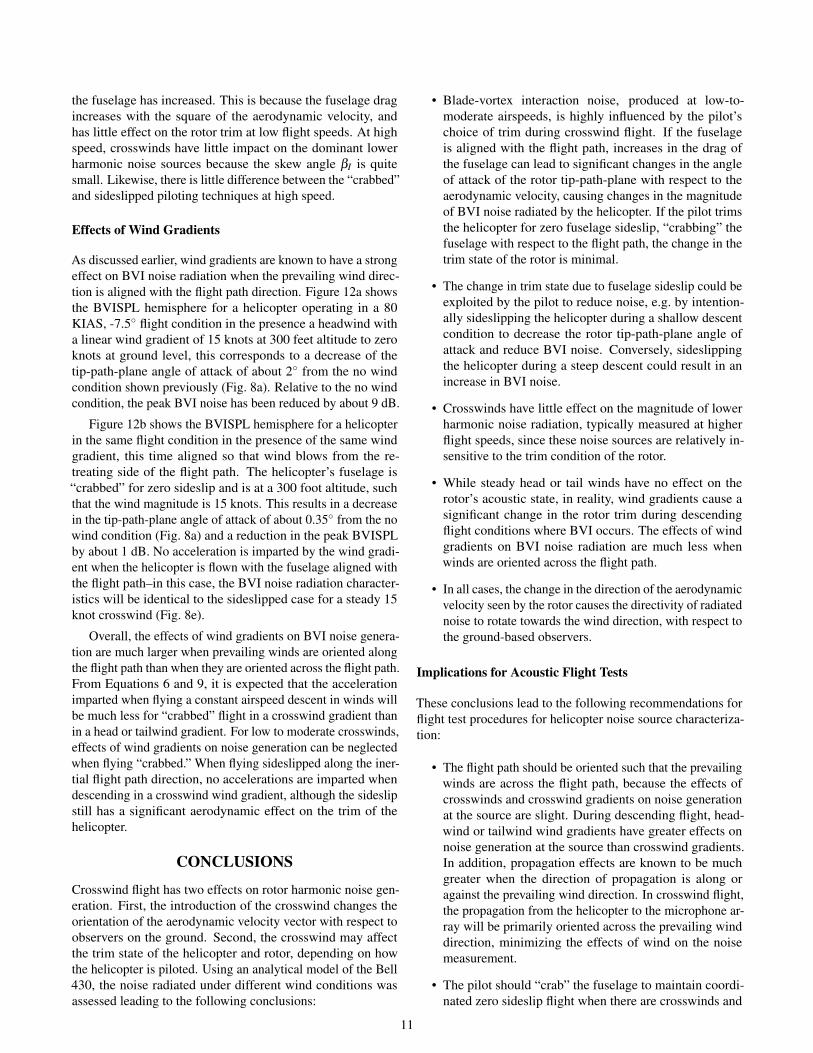
As discussed earlier, wind gradients are known to have a strongeffect on BVI noise radiation when the prevailing wind direc-tion is aligned with the flight path direction. Figure 12a showsthe BVISPL hemisphere for a helicopter operating in a 80KIAS, -7.5� flight condition in the presence a headwind witha linear wind gradient of 15 knots at 300 feet altitude to zeroknots at ground level, this corresponds to a decrease of thetip-path-plane angle of attack of about 2� from the no windcondition shown previously (Fig. 8a). Relative to the no windcondition, the peak BVI noise has been reduced by about 9 dB.
Figure 12b shows the BVISPL hemisphere for a helicopterin the same flight condition in the presence of the same windgradient, this time aligned so that wind blows from the re-treating side of the flight path. The helicopter’s fuselage is“crabbed” for zero sideslip and is at a 300 foot altitude, suchthat the wind magnitude is 15 knots. This results in a decreasein the tip-path-plane angle of attack of about 0.35� from the nowind condition (Fig. 8a) and a reduction in the peak BVISPLby about 1 dB. No acceleration is imparted by the wind gradi-ent when the helicopter is flown with the fuselage aligned withthe flight path–in this case, the BVI noise radiation character-istics will be identical to the sideslipped case for a steady 15knot crosswind (Fig. 8e).
Overall, the effects of wind gradients on BVI noise genera-tion are much larger when prevailing winds are oriented alongthe flight path than when they are oriented across the flight path.From Equations 6 and 9, it is expected that the accelerationimparted when flying a constant airspeed descent in winds willbe much less for “crabbed” flight in a crosswind gradient thanin a head or tailwind gradient. For low to moderate crosswinds,effects of wind gradients on noise generation can be neglectedwhen flying “crabbed.” When flying sideslipped along the iner-tial flight path direction, no accelerations are imparted whendescending in a crosswind wind gradient, although the sideslipstill has a significant aerodynamic effect on the trim of thehelicopter.
CONCLUSIONSCrosswind flight has two effects on rotor harmonic noise gen-eration. First, the introduction of the crosswind changes theorientation of the aerodynamic velocity vector with respect toobservers on the ground. Second, the crosswind may affectthe trim state of the helicopter and rotor, depending on howthe helicopter is piloted. Using an analytical model of the Bell430, the noise radiated under different wind conditions wasassessed leading to the following conclusions:
• Blade-vortex interaction noise, produced at low-to-moderate airspeeds, is highly influenced by the pilot’schoice of trim during crosswind flight. If the fuselageis aligned with the flight path, increases in the drag ofthe fuselage can lead to significant changes in the angleof attack of the rotor tip-path-plane with respect to theaerodynamic velocity, causing changes in the magnitudeof BVI noise radiated by the helicopter. If the pilot trimsthe helicopter for zero fuselage sideslip, “crabbing” thefuselage with respect to the flight path, the change in thetrim state of the rotor is minimal.
• The change in trim state due to fuselage sideslip could beexploited by the pilot to reduce noise, e.g. by intention-ally sideslipping the helicopter during a shallow descentcondition to decrease the rotor tip-path-plane angle ofattack and reduce BVI noise. Conversely, sideslippingthe helicopter during a steep descent could result in anincrease in BVI noise.
• Crosswinds have little effect on the magnitude of lowerharmonic noise radiation, typically measured at higherflight speeds, since these noise sources are relatively in-sensitive to the trim condition of the rotor.
• While steady head or tail winds have no effect on therotor’s acoustic state, in reality, wind gradients cause asignificant change in the rotor trim during descendingflight conditions where BVI occurs. The effects of windgradients on BVI noise radiation are much less whenwinds are oriented across the flight path.
• In all cases, the change in the direction of the aerodynamicvelocity seen by the rotor causes the directivity of radiatednoise to rotate towards the wind direction, with respect tothe ground-based observers.
Implications for Acoustic Flight Tests
These conclusions lead to the following recommendations forflight test procedures for helicopter noise source characteriza-tion:
• The flight path should be oriented such that the prevailingwinds are across the flight path, because the effects ofcrosswinds and crosswind gradients on noise generationat the source are slight. During descending flight, head-wind or tailwind wind gradients have greater effects onnoise generation at the source than crosswind gradients.In addition, propagation effects are known to be muchgreater when the direction of propagation is along oragainst the prevailing wind direction. In crosswind flight,the propagation from the helicopter to the microphone ar-ray will be primarily oriented across the prevailing winddirection, minimizing the effects of wind on the noisemeasurement.
• The pilot should “crab” the fuselage to maintain coordi-nated zero sideslip flight when there are crosswinds and
11

50
55
60
65
70
75
80
85
90
95
100
0o
270 o
180
o 90
o
0 o
!90 o
!60 o
!30 o
0 o
(a) Headwind gradient.
50
55
60
65
70
75
80
85
90
95
100
0o
270 o
180
o
90o
0 o
!90 o
!60 o
!30 o
0 o
(b) Crosswind gradient.
Fig. 12. Predicted BVI noise hemisphere for 80 KIAS, -7.5� FPA flight in a wind gradients, dB BVISPL.
avoid aligning the fuselage with the ground reference,especially as altitude decreases.
• Even when flying in crosswinds, descending “approach”conditions should be flown during low wind conditions.Higher speed level flight “cruise” conditions may be flownin higher wind speeds as they are less sensitive to changesin trim and because the same crosswind will result in asmaller shift in directivity at higher speeds.
ACKNOWLEDGEMENTS
The authors would like to thank Royce Snider of Bell Heli-copter, Michael Watts of NASA Langley Research Center, andCharles Smith of Analytical Mechanics Associates, for theirhelp in preparing this paper, as well as the other members ofthe 2011 NASA/Bell Helicopter/US Army flight test team. Inaddition, thanks to Michael Marcolini and Dr. Thomas Brooksfor helpful discussions during the preparation of this paper.
REFERENCES1Lucas, M. J. and Marcolini, M. A., “Rotorcraft Noise
Model,” AHS Technical Specialists’ Meeting for RotorcraftAcoustics and Aerodynamics, October 1997.
2Conner, D. A. and Page, J. A., “A Tool for Low NoiseProcedures Design and Community Noise Impact Assessment:The Rotorcraft Noise Model (RNM),” Heli Japan, 2002.
3Page, J. A., Wilmer, C., and Plotkin, K. J., “RotorcraftNoise Model Technical Reference and User Manual,” Techni-cal Report WR 08-04, Wyle, February 2008.
4Snyder, J. P., “Map Projections: A Working Manual,” Tech-nical Report PP1395, USGS, 1982.
5Pridmore-Brown, D. C., “Sound Propagation in aTemperature- and Wind-Stratified Medium,” The Journal of theAcoustical Society of America, Vol. 34, (4), 1962, pp. 438–443.doi: 10.1121/1.1918146
6Rasmussen, K., “Outdoor sound propagation under the in-fluence of wind and temperature gradients,” Journal of Soundand Vibration, Vol. 104, (2), 1986, pp. 321 – 335.doi: 10.1016/0022-460X(86)90271-3
7Wiener, F. M. and Keast, D. N., “Experimental Study ofthe Propagation of Sound over Ground,” The Journal of theAcoustical Society of America, Vol. 31, (6), 1959, pp. 724–733.doi: 10.1121/1.1907778
8Sprague, M., Raspet, R., and Ostashev, V. E., “Crosswindeffects on acoustic propagation,” The Journal of the AcousticalSociety of America, Vol. 94, (3), 1993, pp. 1872–1872.doi: 10.1121/1.407628
9Li, Y. L., White, M. J., and Franke, S. J., “New fast fieldprograms for anisotropic sound propagation through an at-mosphere with a wind velocity profile,” The Journal of theAcoustical Society of America, Vol. 95, (2), 1994, pp. 718–726.doi: 10.1121/1.408431
10Sim, B. W., Schmitz, F. H., and Beasman, T., “Blade-VortexInteraction (BVI) Noise of Helicopters Operating in HorizontalWind Shear,” American Helicopter Society 61st Annual Forum,May 2005.
11Greenwood, E. and Schmitz, F. H., “A Parameter Identi-fication Method for Helicopter Noise Source Identificationand Physics-Based Semi-Empirical Modeling,” American He-licopter Society 66th Annual Forum, May 2010.
12Greenwood, E. and Schmitz, F. H., “The Effects of Ambi-ent Conditions on Helicopter Rotor Source Noise Modeling,”American Helicopter Society 67th Annual Forum, May 2011.
12

13Ffowcs Williams, J. E. and Hawkings, D. L., “Sound gener-ation by turbulence and surfaces in arbitrary motion,” Philo-sophical Transactions of the Royal Society of London, Vol. 264,May 1969, pp. 321–342.
14Farassat, F., “Derivation of Formulations 1 and 1A of Faras-sat,” Technical Report TM-2007-214853, NASA, 2007.
15Greenwood, E., Fundamental Rotorcraft Acoustic Model-ing from Experiments (FRAME), Ph.D. thesis, University ofMaryland, January 2011.
16Boxwell, D. A., Schmitz, F. H., Splettstoesser, W. R., andSchultz, K. J., “Helicopter Model Rotor-Blade Vortex Interac-tion Impulsive Noise: Scalability and Parametric Variations,”Journal of the American Helicopter Society, Vol. 32, (1), 1987,pp. 3–12.doi: 10.4050/JAHS.32.3
17Watts, M. E., Snider, R., Greenwood, E., and Baden, J.,“Maneuver Acoustic Flight Test of the Bell 430 Helicopter,”American Helicopter Society 68th Annual Forum, May 2012.
18Beddoes, T. S., “A Wake Model for High Resolution Air-loads,” International Conference on Rotorcraft Basic Research,February 1985.
19van der Wall, B. G., “The Effect of HHC on the VortexConvection in the Wake of a Helicopter Rotor,” AerospaceScience and Technology, Vol. 4, (5), 2000, pp. 321–336.
20Bhagwat, M. J. and Leishman, J. G., “Generalized ViscousVortex Core Models for Application to Free-Vortex Wake andAeroacoustic Calculations,” 58th Annual Forum of the Ameri-can Helicopter Society, June 2002.
21Landgrebe, A. J., “The Wake Geometry of a Hovering Heli-copter Rotor and its Influence on Rotor Performance,” Journalof the American Helicopter Society, Vol. 17, (4), 1972.
22Beddoes, T. S., “Practical Computation of Unsteady Lift,”Vertica, Vol. 8, (1), 1984.
23Leishman, J. G., Principles of Helicopter Aerodynamics,Cambridge University Press, New York, second edition, 2006.
24Schmitz, F. H. and Sim, B. W.-C., “Radiation and Di-rectionality Characteristics of Helicopter Blade-Vortex Inter-action Noise,” Journal of the American Helicopter Society,Vol. 48, (4), 2003, pp. 253–269.
25Squires, P. K., “Investigation of Correlation between Full-Scale and Fifth-Scale Wind Tunnel Test of a Bell HelicopterTextron Model 222,” Technical Report CR-16662, NASA,1982.
26Schmitz, F. H., “Reduction of Blade-Vortex Interaction(BVI) Noise through X-Force Control,” Journal of the Ameri-can Helicopter Society, Vol. 43, (1), 1998, pp. 14–24.doi: 10.4050/JAHS.43.14
13