Embed Size (px)
Citation preview
Loughborough UniversityInstitutional Repository
The effect of pre-servicetreatments on the long term
properties of 9Cr steelsstrengthened by boron and
nitrogen
This item was submitted to Loughborough University's Institutional Repositoryby the/an author.
Citation: SAMMARCO, A., VANSTONE, R. and THOMSON, R.C., 2016.The effect of pre-service treatments on the long term properties of 9Cr steelsstrengthened by boron and nitrogen. IN: Parker, J., Shingledecker, J. andSiefert, J. (eds). Advances in Materials Technology for Fossil Power Plants,Proceedings from the Eight International Conference (EPRI 2016), Albufeira,Algarve, Portugal, 11-14 October 2016, pp. 568-580.
Additional Information:
• This article is made available as an electronic reprint with the permis-sion of ASM International for the Loughborough University InstitutionalRepository. Reproduction, distribution to multiple locations via electronicor other means, duplication of any material in this article for a fee or forcommercial purposes, or modification of the content of this article is pro-hibited.
Metadata Record: https://dspace.lboro.ac.uk/2134/23725
Version: Published
Publisher: c© Electric Power Research Institute (EPRI). Distributed by ASMInternational.
Rights: This work is made available according to the conditions of the Cre-ative Commons Attribution-NonCommercial-NoDerivatives 4.0 International(CC BY-NC-ND 4.0) licence. Full details of this licence are available at:https://creativecommons.org/licenses/by-nc-nd/4.0/

Please cite the published version.
2

THE EFFECT OF PRE-SERVICE TREATMENTS ON THE LONG TERM PROPERTIES OF 9CR STEELS STRENGTHENED BY BORON AND
NITROGEN
A. Sammarco, R. C. ThomsonDepartment of Materials, Loughborough University, Loughborough, LE11 3TU, UK
R. VanstoneGE Power Ltd, Rugby, CV21 2NH, UK
ABSTRACT
Martensitic 9Cr steels have been developed which are strengthened by boron in order to stabilise the microstructure and improve their long-term creep strength. Boron plays a key role in these steels by stabilising the martensitic laths by decreasing the coarsening rate of M23C6 carbides, which act as pinning points in the microstructure.
In this work two modified FB2 steel forgings are compared. Both forgings have similar compositions but one underwent an additional remelting process during manufacture. Creep tests showed that this additional processing step resulted in a significant increase in time to failure. In order to investigate the effect of the processing route on microstructural evolution during agingand creep, a range of advanced electron microscopy techniques have been used including ion beam induced secondary electron imaging and High Angle Annular Dark Field (HAADF) imaging in the Scanning Transmission Electron Microscope. These techniques have enabled the particle population characteristics of all the second phase particles (M23C6, Laves phase, BN and MX) to be quantified for materials from both forging processes.
These quantitative data have enabled a better understanding of how the processing route affectsthe microstructural evolution of FB2 steels.
INTRODUCTION
The need to increase the efficiency of coal fired power plants has led to the introduction of ultra-super-critical (USC) plants with increased operating pressure and temperature, which in turn has led to a need to improve both the materials and manufacturing routes that are used to fabricate the components. Martensitic 9-12% Cr steels have been the key materials used to increase the efficiency of USC power plants [1]. These steels offer a good combination of steam oxidation resistance, high creep strength, low thermal expansion coefficient and good manufacturability [2].
The properties of these steels are derived from their microstructure, which exhibits a tempered martensitic matrix with a fine dispersion of secondary particles. The creep strength of these steels is enhanced by three major mechanisms; precipitation hardening derived from secondary phase particles, dislocation hardening derived from a high dislocation density in the tempered martensite matrix, and solid solution hardening derived from elements such as Mo and W present in solution [3, 4].
Advances in Materials Technology for Fossil Power Plants Proceedings from the Eighth International Conference October 11–14, 2016, Albufeira, Algarve, Portugal
Copyright © 2016 Electric Power Research Institute, Inc. Distributed by ASM International®. All rights reserved.
J. Parker, J. Shingledecker, J. Siefert, editors
568

However, the service conditions in power plants, which include high temperature and stress, result in gradual microstructural degradation of the steels; a process which also reduces the creep strength. Recently a number of attempts have been made to understand how martensitic steels can be improved by investigating the microstructural evolution phenomena during creep, such as precipitation and coarsening of carbonitrides and intermetallic compounds, as well as coarsening of sub-grains [2, 5].
COST 501 and the subsequent COST 522 programs explored the possibility of stabilizing the tempered martensitic microstructure through the addition of small quantities of boron [6, 7]. They resulted in the 9%CrMoCoVNbNB steels (forged FB2 and cast steel CB2) currently being deployed in Europe and the USA to manufacture steam turbine rotors at operating temperatures up to 620ºC [8]. As theorised by several authors [9, 10, 11], boron stabilises the lath martensitic microstructure by decreasing the Ostwald ripening rate of fine M23C6 carbides, which act as pinning points in the microstructure, which in turn leads to improved creep strength. However, the mechanism for the improvement of creep strength by the addition of boron still needs to be clarified.
Boron can also form boron nitride (BN) inclusions, which offset the beneficial effects of boron and nitrogen [10, 12, 13]. Boron and nitrogen additions can be carefully controlled to avoid the formation of BN. It has been reported that the concentration of boron and nitrogen at which BN forms is governed by the equation log[%B]=-2.45log[%N]-6.81 [13]. The boron nitride solubility at elevated temperature (1175ºC to 1200ºC) has been calculated by Li et al. using thermodynamic calculations taking into account the full chemical composition of the steel, including the W concentration, which can influence the formation of tungsten borides [14].
The aim of the present investigation was to quantitatively characterise the microstructural evolution of FB2 forgings before and after creep in order to understand how differences in the manufacturing process can affect the time to failure.
EXPERIMENTAL PROCEDURES
Materials
Table 1 gives the chemical compositions of the two modified FB2 steels studied. In the modified steels the N, Cr and Co contents have been reduced while the B content has been increase compared to the standard composition. The chemical composition of the Standard FB2 steel, indicated as “S” composition, is also listed in table 1 for comparison.
Table 1: Chemical compositions of the modified FB2 steels studied and the standard FB2 (wt.%), balance Fe.
C Mn P S Si Cr Ni Mo V Al W B Nb N Co
C 0.16 0.32 0.0042 0.20 8.85 0.19 1.45 0.21 0.007 5 0.017 0.047 0.0099 0.98
P 0.16 0.31 0.0016 0.19 8.81 0.18 1.43 0.21 0.012 5 0.015 0.044 0.0110 0.97
S 0.14 0.30 - - 9.50 0.15 1.50 0.20 - 5 0.010 0.045 0.0200 1.25
Vacuum induction degassing (VID) was used to produce the ingot, which was forged to produce the ‘C’ material, whereas the ‘P’ material was subjected to an additional pressurised electro-slag
569
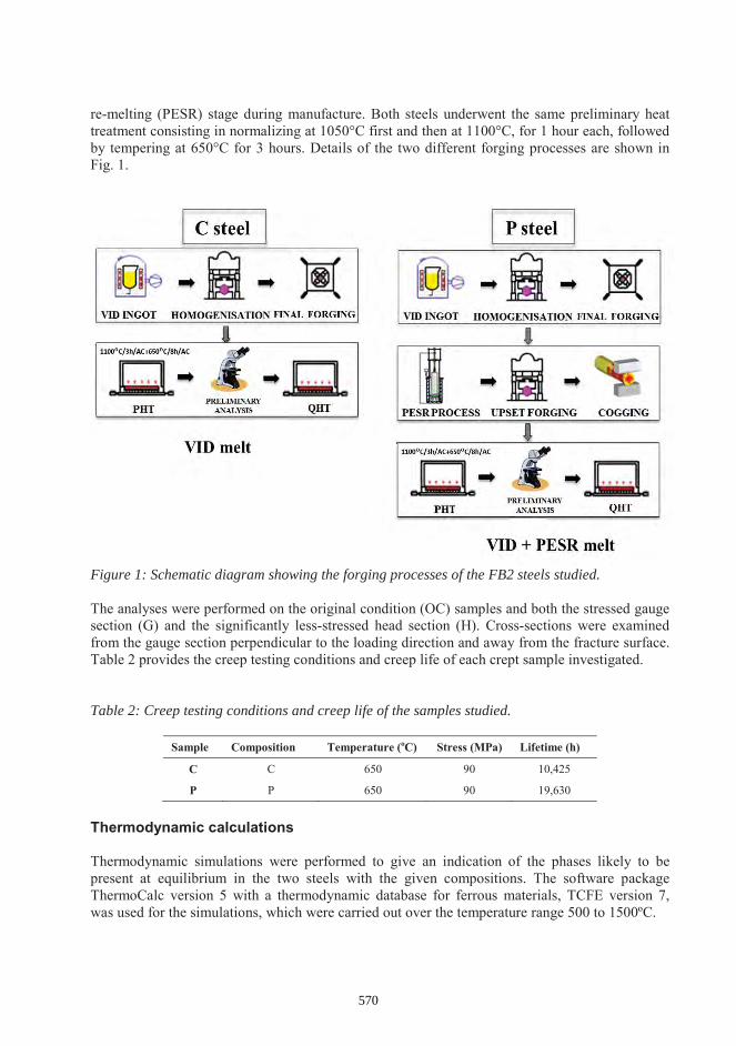
re-melting (PESR) stage during manufacture. Both steels underwent the same preliminary heat treatment consisting in normalizing at 1050°C first and then at 1100°C, for 1 hour each, followed by tempering at 650°C for 3 hours. Details of the two different forging processes are shown in Fig. 1.
Figure 1: Schematic diagram showing the forging processes of the FB2 steels studied.
The analyses were performed on the original condition (OC) samples and both the stressed gauge section (G) and the significantly less-stressed head section (H). Cross-sections were examined from the gauge section perpendicular to the loading direction and away from the fracture surface. Table 2 provides the creep testing conditions and creep life of each crept sample investigated.
Table 2: Creep testing conditions and creep life of the samples studied.
Sample Composition Temperature (oC) Stress (MPa) Lifetime (h)
C C 650 90 10,425
P P 650 90 19,630
Thermodynamic calculations
Thermodynamic simulations were performed to give an indication of the phases likely to be present at equilibrium in the two steels with the given compositions. The software package ThermoCalc version 5 with a thermodynamic database for ferrous materials, TCFE version 7, was used for the simulations, which were carried out over the temperature range 500 to 1500ºC.
570
Sample preparation
Samples were sectioned using a Struers Accutom-5 cutting machine, using an alumina slitting disk. After mounting the sectioned samples in conducting Bakelite, they were ground using 240 to 1200 grit SiC in resin bonded pads, and polished using standard cloths with diamond suspensions down to 1 μm.
Carbon extraction replicas were prepared to study the second phase particle chemistry using Transmission Electron Microscopy (TEM). The samples were prepared by lightly etching the surface of polished and mounted specimens, using Villela’s reagent for 10 seconds. A thin carbon film with a thickness of approximately 20 to 30 nm was then deposited onto the etched metal with a carbon evaporator (Quorum Q150T ES). After scoring the coated surface into squares with a razor blade, an electrolytic etch of 10% HCl in methanol was carried out with a voltage of 1-3V and a current of 30-50 mA to remove the replica from the surface. The specimens were then rinsed in a beaker of pure methanol to remove the electrolyte, and finally immersed in distilled water at a 45º angle, which removed the carbon film with the surface tension of water. Each replica was then collected with tweezers and deposited onto 400 mesh square copper grids.
Microstructural characterisation
An FEI Nova 600 Nanolab dual beam consisting of a Field Emission Gun Scanning Electron Microscope and Focused Ion Beam System (FEG-SEM/FIB) was used for characterizing the carbide population and Laves phase using ion beam etching and back scattered imaging respectively. The FIB was used to generate ion beam-induced secondary electron images. These images, when collected under the appropriate ion dose conditions, provided sufficient contrast between the matrix and particles for automated image analysis to be employed. The collectionparameters used were a 30 kV ion beam, a 30 pA ion beam current, a frame collection speed of 2.4 mins (150 μs dwell time) collecting images with a 25.6 μm horizontal field width (HFW). To distinguish between Laves phase and carbides, which have similar intensity in the ion beam-induced secondary electron images, backscatter electron imaging was employed. To achieve statistically valid data for particle size quantification, a set of 10 images was collected at random locations for each sample.
The dual beam was also equipped with a solid state backscattered electron detector and this was used to characterize the BN particles, in the original condition and aged samples, and Laves phase in the head and gauge sections of the creep samples. BN particles appear dark in the backscattered mode whilst the bright particles were identified as Laves phase. In order to achieve statistically valid data for particle size quantification, a set of 20 images (HFW 128 μm) was collected at random locations for each sample. A silicon drift EDX detector (60mm2 Octane, EDAX) attached to the dual beam was used to perform EDX point analysis on individual dark particles in order to identify BN particles. EDX map analysis was also performed to define the chemical composition of Laves phase detected in the steels. In order to yield an acceptable X-Ray signal intensity and energy resolution, an accelerating voltage of 10 kV was used in conjunction with a nominal current of 23 nA and a working distance of 5 mm.
Measurement of the particle sizes and population was carried out by processing both the ion beam and backscattered images using the UTHSCSA ImageTool 3.0 software. Due to the strong contrast between particles and martensitic matrix, the particles can be successfully differentiated from the matrix using grey scale discrimination. The software was used to measure the size distribution and number density of the particles. Only particles that contained more than 5 pixels
571
(equivalent to 70 nm) were considered to constitute a ‘particle’; particles smaller than this wereconsidered to be noise.
Scanning Transmission Electron Microscopy (STEM) was undertaken using an FEI Tecnai F20 equipped with an X-max N80 TLE (Oxford Instruments) Silicon Drift Detector (SDD) Energy Dispersive Spectrometer (EDS). This system was used to analyze the chemistry of the second phase precipitates present in the carbon extraction replicas using EDS in spot mode. EDS data were collected and processed using Aztec software (Oxford Instruments).
RESULTS AND DISCUSSION
Thermodynamic calculations
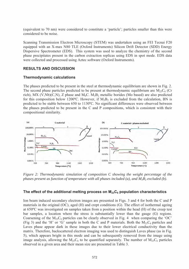
The phases predicted to be present in the steel at thermodynamic equilibrium are shown in Fig. 2. The second phase particles predicted to be present at thermodynamic equilibrium are M23C6 (Cr rich), MX (V,Nb)(C,N), Z phase and M6C. M3B2 metallic borides (Mo based) are also predicted for this composition below 1200ºC. However, if M3B2 is excluded from the calculation, BN is predicted to be stable between 650 to 1130ºC. No significant differences were observed between the phases predicted to be present in the C and P compositions, which is consistent with their compositional similarity.
Figure 2: Thermodynamic simulation of composition C showing the weight percentage of the phases present as function of temperature with all phases included (a), and M3B2 excluded (b).
The effect of the additional melting process on M23C6 population characteristics
Ion beam induced secondary electron images are presented in Figs. 3 and 4 for both the C and P materials in the original (OC), aged (H) and crept conditions (G). The effect of isothermal ageing at 650ºC was investigated on samples taken from a position within the head (H) of the creep test bar samples, a location where the stress is substantially lower than the gauge (G) regions. Coarsening of the M23C6 particles can be clearly observed in Fig. 4 when comparing the ‘OC’(Fig 3) and the ‘H’ or ‘G’ sample in both the C and P materials. Both the M23C6 particles and Laves phase appear dark in these images due to their lower electrical conductivity than the matrix. Therefore, backscattered electron imaging was used to distinguish Laves phase (as in Fig. 5), which appears bright in this mode and can be subsequently removed from the image using image analysis, allowing the M23C6 to be quantified separately. The number of M23C6 particles observed in a given area and their mean size are presented in Table 3.
572

Figure 3: Focused ion beam induced secondary electron images for (a) C-OC and (b) P-OC specimens respectively. All the particles visible in (a) and (b) correspond to the distribution of M23C6.
Figure 4: Focussed ion beam induced secondary electron images for (a) C-H, (b) C-G, (c) P-H
and (d) P-G specimens. The particles visible in the images are a mixture of both M23C6 and Laves
particles; examples of Laves particles are indicated by arrows.
P-OCC-OC
C-H C-G
P-GP-H
573

In the original condition (OC) both the C and P materials had similar average M23C6 particle sizes, although the number of particles per unit area was higher in the P material. In the head sections of both materials the average size of the particles was larger, and the number of particles lower than in the original condition samples. In the gauge sections of both materials the average size of the particles was larger, and the number of particles lower than in the corresponding head section of the sample. In the C sample the average size was much larger than in the P sample, which lasted twice as long as the C material in the creep test. It is evident from Fig. 4 that the exposure to the creep conditions significantly accelerates the coarsening of the M23C6 particles in the modified steel. These results suggests that the stability of M23C6 particles is strongly affected by the additional melting stage in the manufacturing process.
Figure 5: Focussed ion beam induced secondary electron image (a), back scattered image (b) used to distinguish M23C6 from Laves phase (bright particles), and processed image showing M23C6 only.
Table 3: Particle size data for the M23C6 carbides in the C and P samples.
Effect of stress on microstructural evolution of Laves phase
Despite Laves phase have not been predicted to be present in the thermodynamic calculation, a large number of molybdenum rich Laves phase particles were observed in the C and P samples after isothermal aging and creep exposure. Due to its high Mo content, Laves phase particles appears to be brighter than the martensitic matrix in the backscattered electron images, which promotes the atomic number contrast. Using back scattered electron imaging, a bright phase was clearly visible in the head and gauge sections of both the C and P samples, as shown in Fig. 6. This was identified using EDX to be rich in Mo, and is chemically consistent with Laves phase.The effect of stress on microstructural evolution of Laves phase was analysed by comparing the microstructures of the gauge sections with the head sections of the creep tested samples. Large Laves phase particles (of the order of microns in size) were observed in both the materials (C and P). From quantification of the Laves phase, it was found that the area fraction was similar in both
SampleOriginal condition Head Gauge Length
Particle population(655 μm2)
Average size(nm)
Particle population(655 μm2)
Average size(nm)
Particle population(655 μm2)
Average size(nm)
C 2417 101±6 1712 146.3+5 914 175.2+7
P 2748 104±4 1565 152.2+8 711 163.5+6
(c)
5 m
574

materials but higher in the gauge sections than the head sections (Table 4). The average size and number density of the Laves particles in the head and gauge sections of both samples are also shown in Table 4.
Figure 6: Back scattered electron images for (a) C-H, (b) C-G, (c) P-H and (d) P-G specimens respectively. The bright particles visible in the image correspond to Laves phase.
Table 4: Area fraction and particle size data for the Laves phase in the C and P which have been aged and crept.
SampleHEAD GAUGE
Area fraction
Particle population
(16,384μm2)
Average size Area fraction
Particle population
(16,384μm2)
Average size
C 0.0036 ± 0.0002 52.4 0.85 0.0047 ± 0.0005 96.8 1.09P 0.0041 ± 0.0002 59.6 0.91 0.0047 ± 0.0005 90.0 1.15
In both samples there is an increase in the average size and number density in the gauge compared with the corresponding head section. This suggests precipitation is enhanced by stress. No significant differences in the Laves particles population characteristics were observed between the two materials, despite the different ageing/creep time experienced by the samples.
(a) (b)
(c) (d)
50 m 50 m
50 m 50 m
(bC-H C-G
(P-H P-G
575

Effect of BN particles on the microstructural evolution of steels
Back scattered electron imaging combined with EDX was used to detect BN particles in the original condition and head sections of both materials (C and P). BN particles were found in all samples as individual particles or clusters. A typical cluster of BN particles and its respective spectrum are shown in Fig. 7, while back scattered electron images showing characteristic shapes of BN particles in the original condition and and head section samples from both C and P steel are shown if Fig. 8.
Figure 7: Back scattered electron image showing a clustered BN particle from C-OC sample (a). The associated EDS spectrum with clear B and N peaks is shown in (b).
Figure 8: Back scattered electron images showing characteristic shapes of BN particles in the samples; respectively C-OC (a), P-OC (c), C-H (b) and P-H (d).
A set of 10 images per sample were collected and processed using image analysis to quantify the number density, size and area fraction of the BN particles and these data are shown in Tables 5 and 6. These data showed that the area fraction of BN is significantly higher in the C than in the Pmaterial, for both the original condition and head section samples. C-OC and C-H samples showed an area fraction ~10 times higher than P-OC and P-H samples, where just a few isolated BN particles per area have been detected.
(a N (b)
10 m
(a)
5 μm
5 μm
5 μm
5 μm
C-OC C-H
P-OC P-H
(a) (b)
(c) (d)
576

A significant difference in the BN population characteristics has been observed between the two materials, C and P. Both clustered BN particles and individual BN particles were detected in the
-O -Hsample. However, BN was only found as individual particles in the P material, in which the average size of the particles was much smaller than the C material, being 0.98 and 1.16respectively in the P-OC and P-H samples. This substantial difference suggests that the additional re-melting process has significantly affected the BN characteristics in the material.
Table 5: Area fraction of BN particles in the C and P samples.
Sample Original condition Head
C 0.021 ± 0.002 0.017 ± 0.003
P 0.0019 ± 0.0003 0.0022 ± 0.0005
Table 6: Particle size data for the BN particles in the C and P samples
Sample N° of particles per area (512x442μm2) Average size (μm)
Ori
gina
l co
nditi
on C 9 (Clusters and Individual particles) 2.91
P 3 (Individual particles) 0.98
Age
d co
nditi
on
(hea
d se
ctio
n) C 6 (Clusters and Individual particles) 3.40
P 3 (Individual particles) 1.16
In the head sections of the materials, the M23C6 growth rate was slow and similar in both samples, whereas in the gauge sections much faster growth was observed. In these sections the growth rate of M23C6 carbides in the C material (increased BN) was much greater than in the P material (reduced BN). Since the C and P materials have similar B contents, the amount of BN present controls the amount of B in solution, which can stabilise the M23C6 carbides. Therefore, the higher stability during creep of the P material, which had the smaller content of BN particles, could be due to the higher amount of boron in solution, compared to the C material.
Effect of ageing on the chemical composition of MX particles
To analyse the chemical composition of MX carbonitrides and their evolution during ageing, the chemical composition of the MX carbonitrides was measured using TEM-EDS spot analysis on the MX particles present in carbon extraction replicas. For each sample, the measurements were performed on approximately 100 particles, which were randomly sampled.
The chemical evolution of the analyzed particles in the original condition and aged samples of both the C and P materials is shown in the ternary Cr-V-Nb diagrams in Figure 9. Each point represents the composition of the measured particle.
577

Two different particle populations can be distinguished in the ternary diagrams obtained. Indeed, the two particle populations can be identified and classified as; Nb-rich with wt.% Nb >V, and V-rich with wt.% V >Nb. The two populations have a chemical composition consistent with NbC and VN, respectively, and have been detected in all the samples. A range of Nb and V contents were found in the MX particles in both the original condition samples, C-OC and P-OC respectively. It can be seen that the majority of particles measured in the C-OC sample are clustered in the Nb-rich region. However, it can be seen that the majority of particles in the P-OC material are in the V-rich region although it is evident that the width of the distribution in the composition data for the MX precipitates is slightly greater in the P-OC material.
Figure 9: EDS measurements from individual MX precipitates comparing their V, Nb and Cr+Fecontent in (a) C-OC, (b) P-OC, (c) C-H and (d) P-H.
The C and P materials have similar nitrogen contents, and therefore the amount of BN present controls the amount of N in solution, which is important for the precipitation of VN. Therefore, the significant difference in MX chemical composition between the C-OC and P-OC samples could be due to the higher amount of nitrogen in solution in the P-OC sample compared to the C-OC sample as a result of the differences observed in the BN content.
Chemical composition microanalysis of MX precipitates in the aged condition revealed that the vast majority of the MX particle population in both alloys were V-rich. The ternary diagrams highlight that there is a distinct shift in the types of particles observed to be present after ageing in the C-H sample, where no NbC particle were detected. No significant differences were found
578

in the chemical composition of the MX particles analysed in the P-H sample, where most of the particles cluster in the V-rich region and the dispersion in the fraction of Nb, V and Cr is slightly smaller compared to the original condition sample (P-OC).
CONCLUSIONS
Advanced characterisation techniques have been employed to investigate the effect of an additional melting process on the microstructural evolution of an FB2 steel. Creep tests showed that the P forging, which had the additional melting process, lasted twice as long as the C sample. Quantification of M23C6 carbides showed that, despite both forgings having a similar particle size distribution in the original condition, the coarsening of carbides during creep is greater in the C forging than the P forging.
Analysis of the BN particle population identified a significant difference in the BN characteristics between the two materials, with the C material showing a significantly higher content of BN particles than the P material. Differences in morphologies and sizes of BN particles were also identified between the two materials, C and P. Both clustered and individual BN particles were
only found as individual particles in the P material, in which the average size of the particles was smaller than the C material,suggests that the additional re-melting process has significantly affected the BN characteristics in the material. The lower BN content in the P sample could result in an increased concentration of soluble B available to stabilise the M23C6 during creep, resulting in the observed increased creep life.
Large Laves phase particles were observed in both forgings and comparisons between the head and gauge sections of creep samples revealed an increase in the particle population density and a slightly smaller average size in the gauge length compared with the head, suggesting precipitation is enhanced by strain. The chemical analysis of the MX particles showed a significant difference between the original condition C and P samples. Since the C and P materials have similar nitrogen contents, the amount of BN present controls the amount of N in solution, which can precipitate VN particles. Therefore, the significant difference in MX chemical composition between the C-OC and P-OC samples could be due to the higher amount of nitrogen in solution in the P-OC compared to the C-OC sample as a function of differences in the BN distribution.The Nb-rich particles in the C-OC sample, however, were found to transform to V-rich after ageing.
ACKNOWLEDGEMENTS
The authors would like to acknowledge the Engineering and Physical Sciences Research Council UK through the Doctoral Training Centre Grant No. EP/G037345/1 and GE Power for financial support of this project. Dr. F. Kauffman from MPA Stuttgart and the members of the KMM-VIN Network, Materials for Energy, are also thanked for their valuable contributions to the project.
REFERENCES
[1] Vanstone, R. W., “Alloy design and microstructural control for improved 9-12%Cr power plant steels,” COST 522 Steam Power Plant, Final Report, Annex A (1998-2003)
579

[2] Hald, J., “Development status and future possibilities for martensitic creep resistant steels,” Proc. 9th Liege Conf. on Materials for Advanced Power Engineering, Liege, Belgium, 2010, pp.55-66
[3] Hald, J., “Microstructure and long-term creep properties of 9-12% Cr steels,” International Journal of Pressure Vessels and Piping, Vol 85, (2008), pp. 30-37, 282-299
[4] Maruyama, K., Sawada, K., Koike, J., “Strengthening Mechanisms of Creep Resistant Tempered Martensitic Steels,” ISIJ International, Vol. 4, No. 6 (2001), pp. 641-653
[5] Hald, J., Korcakova, L., “Precipitates stability in creep resistant ferritic steels experimental investigations and modelling,” ISIJ International, Vol. 43 (2003), pp. 420-427
[6] Kern, T-U., Staubli, K.H., Mayer, K., Zeiler, G., “The European Effort in developing rotor materials up to 650ºC,” Proc. 9th Liege Conf. on Materials for Advanced Power Engineering,Liege, Belgium, 2002
[7] Staubli, M., Mayer, K. H., Gieselbrecht W., Stief, J., Di Gianfrancesco, A., Kern, T-U., “Development of creep resistant cast steels within the European collaboration in advanced steam turbine materials for ultra efficient, low emission steam power plant,” Proc. 9th Liege Conf. on Materials for Advanced Power Engineering, Liege, Belgium, 2002
[8] Vanstone, R., Chilton, I., Jaworski, P., “Manufacturing experience in an advanced 9%CrMoCoVNbNB alloy for ultra-supercritical steam turbine rotor forgings and castings”,ASME Journal Engineering for gas turbines and power, Vol. 135, No 6 (2013)
[9] Hattestrand, M., Andren, H., “Boron distribution in 9–12 % chromium steels,” Materials Science and Engineering. Vol. 270, No 1 (1999), pp. 33–37
[10] Abe, F., “Precipitate design for creep strengthening of 9% Cr tempered martensitic steel for ultra-supercritical power plants,” Mater. Sci. Adv. Technol. A, Vol.9, No 1 (2008)
[11] Abe, F., Horiuchi, T., Taneike, M., Sawada, K., “Stabilization of martensitic microstructure in advanced 9% Cr steel during creep at high temperature,” Mater. Sci. Adv. Technol. A, Vol.378 (2004), pp. 299-303
[12] Abe, F., “Effect of Boron on Microstructure and Creep Strength of Advanced Ferritic Power Plant Steels,” Procedia Eng., Vol.10 (2011), pp.94-99
[13] Sakuraya, K., Okada, H., and Abe, F., “BN type inclusions formed in high Cr ferritic heat resistant steel,” Energy Materials, Vol. 1 (2006), pp. 158-166
[14] Li, L., MacLachlan, R., Jepson, M.A.E., Thomson, R.C., “Microstructural Evolution of Boron Nitride Particles in Advanced 9Cr Power Plant Steels,” Metallurgical and Materials Transactions A, Vol 44, No 7 (2013), pp. 3411-3418
580