Embed Size (px)
Citation preview

DOT/FAA/AR-06/28 Office of Aviation Research and Development Washington, DC 20591
The Effect of Peel-Ply Surface Preparation Variables on Bond Quality August 2006 Final Report This document is available to the public through the National Technical Information Service (NTIS), Springfield, Virginia 22161.
U.S. Department of Transportation Federal Aviation Administration

NOTICE
This document is disseminated under the sponsorship of the U.S. Department of Transportation in the interest of information exchange. The United States Government assumes no liability for the contents or use thereof. The United States Government does not endorse products or manufacturers. Trade or manufacturer's names appear herein solely because they are considered essential to the objective of this report. This document does not constitute FAA certification policy. Consult your local FAA aircraft certification office as to its use. This report is available at the Federal Aviation Administration William J. Hughes Technical Center’s Full-Text Technical Reports page: actlibrary.tc.faa.gov in Adobe Acrobat portable document format (PDF).

Technical Report Documentation Page 1. Report No. DOT/FAA/AR-06/28
2. Government Accession No. 3. Recipient's Catalog No.
5. Report Date August 2006
4. Title and Subtitle THE EFFECT OF PEEL-PLY SURFACE PREPARATION VARIABLES ON BOND QUALITY
6. Performing Organization Code
7. Author(s) Brian Flinn and Molly Phariss
8. Performing Organization Report No. 10. Work Unit No. (TRAIS)
Performing Organization Name and Address Department of Material Science and Engineering University of Washington Seattle, WA 98103
11. Contract or Grant No. 13. Type of Report and Period Covered Final Report
12. Sponsoring Agency Name and Address U,S. Department of Transportation Federal Aviation Administration Office of Aviation Research and Development Washington, DC 20591
14. Sponsoring Agency Code ANM-115N
15. Supplementary Notes The Federal Aviation Administration Airport and Aircraft Safety R&D Division COTR was Peter Shyprykevich. 16. Abstract To further understand the effect of the variables present in surface preparation on the durability of cobonded and secondary-bonded composite joints, surface analysis coupled with mechanical testing and fractography were used to analyze samples prepared using peel-ply removal as the sole surface preparation technique. Laminates were made from aerospace carbon fiber prepreg and bonded with two different film adhesives. Nylon and polyester peel plies, and siloxane-coated release fabrics, were investigated to determine the effect of peel-ply material on bond quality and to examine why some peel-ply/adhesive systems are incompatible. Varying weaves of nylon and polyester peel plies were used to investigate the effect of peel-ply texture (weave) on bond quality. The moisture content of polyester peel plies was varied to examine its effect on bond quality. Laminate surfaces and peel plies were analyzed after peel-ply removal through scanning electron microscopy (SEM) and x-ray photoelectron spectroscopy (XPS); the results of which were correlated to Mode I double cantilever beam strain energy release rates to determine bond quality. Uncoated polyester peel plies were easily removed from laminate surfaces after curing and produced good bonds with both adhesives for all textures (GIC> 850 J/m2, cohesive failure). Super Release Blue-coated polyester peel ply created surfaces that bonded very poorly in both cases (GIC< 94 J/m2, adhesion failure), the result of the transfer of the peel-ply siloxane coating to the composite surface. Nylon peel plies were more difficult to remove from the laminate and, in the coarser weaves, could not be removed without damaging the laminates. Laminate surfaces prepared with nylon peel plies bonded well with AF555 (GIC> 750J/m2, cohesive failure). Laminate surfaces prepared with nylon peel plies bonded poorly with MB1515-3 (GIC<150 J/m2, adhesion failure). This may be explained by the transfer of nylon to the prepared surface, which was found during SEM and XPS analysis. Peel-ply texture or peel-ply moisture content had no significant effect on fracture energy or mode of failure.
17. Key Words Adhesive bonding, Surface preparation, Carbon fiber composites, Wettability
18. Distribution Statement This document is available to the public through the National Technical Information Service (NTIS), Springfield, Virginia 22161
19. Security Classif. (of this report) Unclassified
20. Security Classif. (of this page) Unclassified
21. No. of Pages 35
22. Price
Form DOT F 1700.7 (8-72) Reproduction of completed page authorized

TABLE OF CONTENTS
Page
EXECUTIVE SUMMARY ix 1. INTRODUCTION 1
1.1 Motivation 1 1.2 Related Previous Work 1 1.3 Primary Preparation Technique 2
2. EXPERIMENTAL APPROACH 3
2.1 Sample Preparation 3 2.2 Characterization 7
2.2.1 X-Ray Photoelectron Spectroscopy 7 2.2.2 Scanning Electron Microscopy 8 2.2.3 Contact Angle Measurement 8
2.3 Mechanical Testing and Fractography 9
3. RESULTS AND DISCUSSION 9
3.1 Effect of Peel-Ply Material 9 3.2 Effect of Peel-Ply Texture 16 3.3 Effect of Peel-Ply Moisture 21 3.4 Determination of Surface Energy by Contact Angle 21
4. CONCLUSIONS 25
5. REFERENCES 25
iii

LIST OF FIGURES Figure Page 1 Photomicrograph of Cured Part Cross Section 2 2 Four Possible Fracture Modes in Peel Ply Removal 3 3 Scanning Electron Microscopy Micrographs of PFG Peel-Ply Fabrics Used
in This Study 5 4 Double Cantilever Beam Specimen and Panel Geometry and Dimensions, Plan View 6 5 Peel-Ply Removal With no Observable Laminate Damage 7 6 Examples of Laminates Damaged During Removal of Some Nylon Peel Plies 7 7 Double Cantilever Beam Test Results of Laminates Prepared With Polyester or SRB
Peel Ply and Bonded With MB1515-3 10 8 Mode I Strain Energy Release Rate of Laminates Bonded With AF555 or MB1515-3 11 9 Scanning Electron Microscopy of Composite Surface After Removal of Polyester,
Nylon, and SRB 12 10 Polyester, Nylon, and SRB Fabric After Removal From Laminate 13 11 Nylon-Prepared Composite Surface 13 12 X-Ray Photoelectron Spectroscopy Composition Scan Spectra of Control Laminate
Surface, Polyester, Nylon, and SRB Peel Plies 14 13 High-Resolution C (1s) Spectra of Epoxy Control, Polyester, Nylon, and SRB 15 14 Laminate Surfaces After Removal of Peel Plies 17 15 Peel Plies After Removal From Cured Laminate 18 16 Scanning Electron Microscopy Image of Removed PFG Peel-Ply 60001 and 41661
Illustrating Damage to Peel-Ply Filaments in the Latter 19 17 Average GIC of Laminates Prepared With Various Peel Plies and Bonded With
AF555 or MB1515-3 20 18 Average GIC of Laminates Prepared With 60001 Peel Ply Conditioned at Various
Humidity Levels and Bonded With AF555 21
iv

19 Linear Kaelble Plot for Surface Energy Measurement From Contact Angle Data on BMS8-276 Laminate Prepared With PFG 60001 Peel Ply 22
20 Wettability Envelopes for BMS8-276 Laminates Prepared With PFG Polyester Peel Plies 23 21 Wettability Envelopes for BMS8-276 Laminates Prepared With PFG Nylon
Peel Plies 24 22 Wettability Envelopes for BMS8-276 Laminates Prepared With PFG Nylon
Peel Ply 51879 and Polyester Peel Ply 60001 24
v

LIST OF TABLES Table Page 1 Weave Characteristics of PFG Peel-Ply Fabrics Used in This Study 4 2 Fracture Surfaces of Tested Laminates 10 3 Scanning Electron Microscopy Image of Adhesive Side of Fracture Surfaces From
DCB Specimens 12 4 Relative Concentrations of Elements Found on Laminate Surfaces by XPS 14 5 Carbon Bonding in Samples After Peel-Ply Removal 15 6 Summary of Average GIC Data and Failure Mode for Laminates Prepared With
Various Peel Plies and Bonded With AF555 and MB1515-3 20 7 Contact Angle Measurements and Surface Energies for a Variety of Fluids Measured
on BMS8-276 Laminates Prepared With Different Peel Plies 22
vi

LIST OF ACRONYMS
DCB Double cantilever beam DMSO Dimethyl sulfoxide PFG Precision Fabrics Group RH Relative humidity SEM Scanning electron microscopy SRB Super Release Blue XPS X-ray photoelectron spectroscopy
vii/viii

EXECUTIVE SUMMARY
The understanding of composite bonding lags behind that of metals. Although techniques to achieve good bond strength in composites have been developed, the role of surface-preparation techniques, such as peel-ply removal at the fundamental level, is poorly understood. Peel-ply removal is widely used for bonding composite primary structures, but is a technique with several variables which the effect on bond quality has not been fully investigated. To further understand the effect of the variables present in surface preparation on the durability of cobonded and secondary-bonded composite joints, surface analysis, coupled with mechanical testing and fractography, were used to analyze samples prepared using peel-ply removal as the sole surface preparation (no abrasion). Nylon and polyester peel plies, and siloxane-coated release fabric, were investigated to determine the effect of peel-ply material on bond quality and to examine why some peel-ply/adhesive systems are incompatible. To investigate the effect of peel-ply texture (weave) on the quality of cobonded and secondary-bonded composite joints, laminates were prepared using nylon and polyester peel plies with fine to rough weaves. The effect of peel-ply moisture content was investigated by preparing laminates with polyester peel plies with different moisture contents. The laminates were made from aerospace carbon fiber prepreg and bonded with two different film adhesives. Laminate surfaces and peel plies were analyzed after peel-ply removal through scanning electron microscopy (SEM) and x-ray photoelectron spectroscopy (XPS); the results of which were correlated to Mode I double cantilever beam strain energy release rates to determine bond quality. Finally, fractography was performed with SEM to determine the mode of fracture. Uncoated polyester peel plies were easily removed from laminate surfaces after curing and produced good bonds with both adhesives for all textures (GIC> 850 J/m2, cohesive failure). Super Release Blue-coated polyester peel ply created surfaces that bonded very poorly in both cases (GIC< 94 J/m2, adhesion failure), the result of the transfer of the peel-ply siloxane coating to the composite surface. Nylon peel plies were more difficult to remove from the laminate and, in some cases, could not be removed without damaging the laminates. Finer weaves were easier to remove than coarser weaves. Laminate surfaces prepared with nylon peel plies bonded well with AF555 (GIC> 750J/m2, cohesive failure). Laminate surfaces prepared with nylon peel plies bonded poorly with MB1515-3 (GIC<150 J/m2, adhesion failure). This may be explained by the transfer of nylon to the prepared surface, which was found during SEM and XPS analysis. Peel- ply texture or peel-ply moisture content had no significant effect on fracture energy or mode of failure.
ix/x

1. INTRODUCTION.
1.1 MOTIVATION.
Joints represent one of the greatest challenges in the design of structures in general and of composite structures in particular. Joints entail interruptions in the geometry of a structure and often material discontinuities. The latter almost always produce localized areas of high stress. In principle, adhesive joints are structurally more efficient than mechanically fastened joints; therefore, they offer the potential for structural weight saving because they provide better opportunities for eliminating stress concentrations. For example, advantage can be taken of ductile response of the adhesive to reduce stress peaks [1]. Mechanically fastened joints tend to use the available material inefficiently. However, adhesive joints tend to lack structural redundancy and are highly sensitive to manufacturing deficiencies, including poor bonding technique, poor fit of mating parts, and sensitivity of the adhesive to temperature and environmental effects such as moisture [2]. Assurance of bond quality has been a continuing problem in adhesive joints. While ultrasonic and x-ray inspection may reveal gaps in the bond, no technique currently available can guarantee that a bond that appears to be intact does, in fact, have adequate load transfer capability. Most joint design principles are irrelevant if adhesion between the adherends is poor. Integrity of a bond hinges on strong primary chemical bonding and, to a lesser degree, mechanical factors [3]. Surface preparation is the most important factor because it can remove contamination from the environment or left from processing and can create chemically active surfaces [1]. It is, therefore, of the utmost importance that surfaces be properly prepared to create strong bonds. Surface preparation and bonding techniques have been well developed for metal-to-metal bonding; however, this is not the case for composite-to-composite or composite-to-metal bonding. Techniques to achieve good bond strength in composites have been developed, but there is not a fundamental understanding of the role of surface preparation techniques at the atomic level. 1.2 RELATED PREVIOUS WORK.
Sanding, grit blasting, and peel-ply removal are three common methods used to prepare composite surfaces for adhesive-bonding [4]. The effect of surface roughness and material removal on bond quality has been investigated for abrasive surface preparation techniques [2 and 5]. Bossi showed an increase in strain energy release rate in grit-blasted samples as surface roughness increased, and a corresponding change in failure mode from interfacial (adhesion) to cohesive and finally interlaminar [5]. No published work has been found with respect to the effect of surface texture from peel ply prepared on bond quality. The moisture content of prepregs, laminates, and adhesives has been shown to have a strong, negative effect on bond quality [6]. Quality control procedures are commonly used to ensure low-moisture content in prepregs, laminates, and adhesives. Hart-Smith has mentioned that moisture absorbed in nylon peel plies has been identified as a contributing problem [6]. Armstrong vaguely references research by J.R.J Wingfield on the effect of peel-ply moisture, but no publications were found [7]. The authors have not been able to find any published research that investigated the effect of
1

wet polyester peel ply on surface preparation, or any manufacturers’ specifications with respect to moisture content or storage requirements for peel ply. 1.3 PRIMARY PREPARATION TECHNIQUE.
Peel ply is added as the last layer in the lay-up of the composite part to be bonded. During cure, the epoxy in the part becomes viscous and flows into gaps in the peel ply. This can be seen in the cross-section of the Precision Fabrics Group (PFG), Inc., 40000 nylon peel ply on a cured laminate shown in figure 1. The peel ply is removed from the surface immediately before bonding.
FIGURE 1. PHOTOMICROGRAPH OF CURED PART CROSS SECTION The characteristics of a surface created by peel ply removal are directly influenced by how the peel ply separates from the laminate. The possible types can be seen in figure 2, and are either (1) the fracture of the epoxy resin between the peel ply and the underlying carbon fibers (dark blue) or (2) interfacial fracture between the peel-ply fabric fibers and the epoxy matrix (pink). In severe cases of poor surface preparation, the peel-ply fibers may fracture and leave material on the composite surface (3 green) or there may be interlaminar failure in the composite (4 turquoise). In the first type, a fresh epoxy surface is created that should be chemically active and easily bonded. Though ideal, this is rarely the only mode of fracture present. In the second type, the chemistry of the surface created may be affected by the nature of the peel-ply material surface. Peel-ply coatings or fiber surface treatments may be transferred to the surface to be bonded and affect the future bond [8]. The third type may occur if the bond between the peel ply
2

and epoxy is stronger than the peel-ply fibers and the fourth if the interlaminar strength of the laminate is low or the peel ply is removed incorrectly.
FIGURE 2. FOUR POSSIBLE FRACTURE TYPES IN PEEL PLY REMOVAL
Additionally, peel plies that may work for one resin or adhesive system may be ineffective with others. Although trial and error in industrial practice has shown what combinations create strong bonds, there remains a lack of understanding of the mechanisms occurring on a fundamental level. The goal of this research is, therefore, to further understand the effect of peel-ply fabric characteristics on laminate surfaces being prepared for bonding with film adhesives through surface analysis coupled with mechanical testing and fractography. 2. EXPERIMENTAL APPROACH.
2.1 SAMPLE PREPARATION.
Unidirectional ten-ply laminates [0]10T were laid up using 0.30 by 0.50 m, 176oC cure aerospace carbon fiber/epoxy prepreg strips and covered with a layer of polyester or nylon peel- ply fabric, and then vacuum bagged. Laminates were produced using nine different peel-ply fabrics from PFG listed in table 1. The texture and weave of the as-received plies can be seen in figure 3.
3

TABLE 1. WEAVE CHARACTERISTICS OF PFG PEEL-PLY FABRICS USED IN THIS STUDY
Filament Material
Precision Fabrics Code
Warp (ends/mm) (ends/in.)
Fill (picks/mm) (ends/in.)
Peel Ply Thickness
(mm)
Comments
Polyester 60001 2.75 (70) 1.97 (50) 0.13-0.15 BMS8-308
Polyester 60001 SRB 2.75 (70) 1.97 (50) 0.13-0.15 Siloxane Coated
Polyester 60004 VLP 4.72 (120) 2.32 (59) 0.13-0.15 Calendered
Polyester 60004 4.72 (120) 2.32 (59) 0.11- 0.14
Polyester 60005 3.54 (90) 2.28 (58) 0.15-0.18
Nylon 6,6 51789 6.30 (160) 4.06 (103) 0.11-0.14 Very Fine
Nylon 6,6 52008 3.98 (101) 3.23 (82) 0.10-0.13
Nylon 6,6 50000 2.36 (60) 1.97 (50) 0.17-0.19 Twill weave
Nylon 6,6 40000 2.99 (76) 2.01 (51) 0.19-0.22
Nylon 6,6 41661 2.36 (60) 1.97 (50) 0.17-0.19 Coarse
The peel plies were chosen to produce laminate surfaces for bonding with a wide range of surface finishes. All peel plies were stored at ambient conditions (20oC and 50% +10% relative humidity (RH)). In addition, one commonly used polyester peel ply (60001) was selected for conditioning at various temperatures and humidity levels prior to laminate fabrication to investigate if moisture in the peel ply affects the surface to be bonded. The 60001 peel-ply samples were weighed and then placed in environmental chambers at 25oC-90% RH and 60oC-90% RH. The mass change of the peel-ply samples was measured at 0.5, 1, 2, 4, and 18 hours. One sample of peel ply was placed in a drying oven at 60oC for 18 hours. The sample conditioned at 60oC-90% RH gained 25% mass after 0.5 hours and then stabilized. The sample conditioned at 25oC-90% RH did not exhibit any measurable change in mass. Laminates were fabricated using the wet and dry peel plies within 1 hour of removal from conditioning chamber.
4

Polyester Peel-Ply Fabrics Nylon Peel-Ply Fabrics
6000
1
5178
9
6000
1SR
B
5200
8
6000
4VLP
5000
0
6000
4VLP
4000
0
6000
5
4166
1
FIGURE 3. SCANNING ELECTRON MICROSCOPY MICROGRAPHS OF PFG PEEL-PLY
FABRICS USED IN THIS STUDY
5

All laminates underwent a standard cure cycle of 176oC for 2 hours under 0.58 MPa in an autoclave with full vacuum maintained throughout the cure cycle. The ends of the laminates were then removed for surface characterization with peel ply intact. After trimming the laminate panels to dimensions specified in figure 4, peel plies were removed immediately before application of epoxy-based film adhesives MB1515-3 or AF555. A strip of nonporous fluorinated ethylene propylene release film was placed between the halves to be bonded to create an initial debond for fracture toughness testing as seen in figure 4. Bonded samples were cured using the same conditions as the laminates.
FIGURE 4. DOUBLE CANTILEVER BEAM SPECIMEN AND PANEL GEOMETRY AND DIMENSIONS, PLAN VIEW
All polyester peel plies were easily removed from the laminates with no damage to laminate or peel-ply filaments observed, as shown in figure 5. Nylon peel plies were difficult to remove from the cured laminates and required much greater force to peel away the fabric. Despite several attempts by experienced technicians, PFG nylon peel plies coded 52008, 50000, and 41661 could not be removed without causing significant damage to the laminates, as shown in figure 6, Interlaminar fracture occurred during peel ply removal leaving carbon fiber attached to the nylon peel plies. Only laminates from which the peel ply could be removed without damage to laminate were approved for bonding. Hence, there is no GIC data for samples prepared with 52008, 50000, or 41661 peel plies. Double cantilever beam (DCB) specimens were machined from the coupon after bonding, as shown in figure 4.
6

FIGURE 5. PEEL-PLY REMOVAL WITH NO OBSERVABLE LAMINATE DAMAGE
FIGURE 6. EXAMPLES OF LAMINATES DAMAGED DURING REMOVAL OF SOME NYLON PEEL PLIES
2.2 CHARACTERIZATION.
2.2.1 X-Ray Photoelectron Spectroscopy.
When Surface Science Instruments M-Probe spectrometer was used for the x-ray photoelectron spectroscopy (XPS) analyses of the laminate surface in a high vacuum, the environment pressure did not exceed 1.3x10⁻⁶ Pa. The peel-ply material was removed from laminates by peeling back from the center of the short edge of the coupons immediately prior to analysis. A cured laminate was split and the untreated surface scanned as a control. Survey scans and high-resolution XPS spectra over the C (1s) peak were recorded in three spots per sample to find chemical composition using nominal pass energies of 150 and 50 eV, respectively. Spectra were obtained from elliptical spots with major axes of approximately 1.7 mm and minor axes of approximately 0.4 mm, to depths of between 10 and 20 atom layers of the sample surface. The samples were nonconducting; therefore, a low-energy electron load-gun set at ~4.0 eV was used for charge
7

neutralization of the samples. All spectra measurements were corrected for the charging by setting the C (1s) peak to 285.0 eV. 2.2.2 Scanning Electron Microscopy.
Scanning electron microscopy (SEM) is a technique in which the emission of secondary electrons from a sample is analyzed to create magnified images of a surface. Insulating samples must be covered in a thin conductive coating before analysis. An electron beam of an energy ranging from a few keV to 50 keV is emitted from a cathode filament with high-melting point and low-vapor pressure, such as tungsten or lanthanum hexaboride LaB6, an anode, or via field emission. The electron beam is focused by two successive condenser lenses into a beam with a very fine spot size (~ 5 nm), passes through the objective lens, and is deflected by pairs of scanning coils either linearly or in a raster fashion over a rectangular area of the sample surface. As the primary electrons strike the surface, they are inelastically scattered by atoms in the sample and cause emission of electrons that are then detected to produce an image. The most common imaging mode monitors low-energy (<50 eV) secondary electrons. SEM gives images with good three-dimensional contrast because the surface area, which is relatively small for a flat surface but increases for a steep surface, that is exposed to the primary beam determines the brightness of the signal. The spatial resolution of the SEM falls somewhere between 3 and 20 nm and depends on the size of the electron spot, which is determined by magnetic electron-optical system that produces the scanning beam. The resolution is also limited by the extent of the material that interacts with the electron beam. The SEM cannot image down to the atomic scale, because the spot size and interaction volume are very large compared to the distances between atoms. The SEM can, however, image a comparatively large area of the specimen, image bulk materials, and has a variety of analytical modes available for measuring the composition and nature of the specimen [9]. In this study, SEM was used to characterize the morphology of the peel plies before and after use and the laminate surface created by peel-ply removal, yielding visual topographic results. In addition, fractography was performed using SEM. Postfracture images show whether specific features acted as crack initiation sites, and they can distinguish between interfacial failure and thin-layer cohesive failure. SEM can also expose if there are small patches of interfacial failure in a primarily cohesive failure (or vice versa). 2.2.3 Contact Angle Measurement.
As is clear from a review of adhesion theory, contact angle measurements are a very powerful tool in understanding surfaces. They are also very simple to perform. A liquid drop is placed (not dropped in order to decrease the gravitational effect) on a surface that does not swell or react. Very viscous liquids are given some time to equilibrate. A goniometer is then used to measure the angle between the surface and the drop, with the crosshairs aimed at the drop edge [10]. At the University of Washington, contact angles are measured with a Ramé-Hart Tilting Contact Angle Goniometer Model 100-00115 with an overall magnification of 23 times and working distance 57 mm. The measurement is dependent on the direction it is taken. The advancing angle of a drop will be greater than the receding angle. This is known as contact
8

angle hysteresis, and is caused by nonhomogeneous-surface chemistry, surface roughness, and molecular rearrangement in the solid from the liquid (or vice versa). All measurements reported here are advancing angle. The fluids used were deionized water, dimethyl sulfoxide (DMSO), glycerol, and ethylene glycol. Contact-angle measurements were taken 5-10 seconds after the drop was placed on the laminate surface. Ten measurements were taken on each laminate using the Kaelble approach as discussed by Bossi, et al. [5] surface. Using the Kaelble approach as discussed by Bossi, et al. [5], surface energies and wettability envelopes were calculated by fitting. 2.3 MECHANICAL TESTING AND FRACTOGRAPHY.
A DCB test was performed according to ASTM D5528-01 standards using a servo-hydraulic test frame with a 200N-load cell and 25-mm/min ramp rate on bonded specimens to determine GIC values. Generally used to evaluate composite parts, this test was used in this study as a measure of joint bond quality. Ten samples prepared with each peel ply were tested. Fractography was performed using SEM. Postfracture images show whether specific features acted as crack initiation sites, and they can distinguish between interfacial failure and thin-layer cohesive failure. SEM can also expose if there are small patches of interfacial failure in a primarily cohesive failure (or vice versa). 3. RESULTS AND DISCUSSION.
3.1 EFFECT OF PEEL-PLY MATERIAL.
To examine the effect of peel-ply material on bond quality, the results from Mode I DCB fracture toughness test of 60001, 52008, and 60001 Super Release Blue (SRB)-prepared surfaces were compared. The DCB test produced a load displacement plot, data for crack extension, a failure mode, and a corresponding critical-strain energy release rate. The load displacement plots were very indicative of the crack events that occurred during the DCB test, as shown in figure 7. In both load displacement plots, the initial linear portion of the curve shows where the specimen is being loaded through the precracked region up to the peak of the curve where a new crack begins. The initial slopes are dissimilar due to differing initial crack lengths. The laminates cured with an SRB-release ply displayed steady crack growth, as indicated by the nearly linear trend of decreasing load. The polyester-prepared specimen displayed stable crack growth up to a point upon which rapid (nonsteady) crack growth occurred, as indicated by the instantaneous drop in load. The linear portion tracing back to zero load and displacement shows the unloading of the specimen. Based on the combination of the DCB plots and the fracture surfaces shown in table 2, it seems that stable crack propagation predominated in all samples. Three types of failure were observed: (1) adhesion failure at the adhesive/adherend bondline, (2) cohesive failure in the adhesive layer, and (3) a mix of cohesive and interlaminar failure. Types of failure were confirmed by SEM.
9

0.0
5.0
10.0
15.0
20.0
25.0
30.0
35.0
0.0 5.0 10.0 15.0 20.0 25.0 30.0 35.0 40.0 45.0 50.0
Displacement (mm)
Load
(N)
Polyester
SRB
FIGURE 7. DOUBLE CANTILEVER BEAM TEST RESULTS OF LAMINATES PREPARED WITH POLYESTER OR SRB PEEL PLY AND BONDED WITH MB1515-3
TABLE 2. FRACTURE SURFACES OF TESTED LAMINATES
Polyester Prepared Nylon Prepared SRB Prepared
AF555
Failure Type Cohesive Cohesive & Interlaminar Adhesion
MB1515-3
Failure Type Cohesive Adhesion Adhesion
Sample width = 12.7
10

910.7 909.6
1000.0
93.9122.1
812.3
86.0
0.0 100.0 200.0 300.0 400.0 500.0 600.0 700.0 800.0 900.0
52008 (Nylon)
60001 (Polyester)
SRB (Polyester)
Peel Ply
AF 555 MB 1515-3
FIGURE 8. MODE I STRAIN ENERGY RELEASE RATE OF LAMINATES BONDED
WITH AF555 OR MB1515-3 The measure of bond quality for this purpose is the critical-strain energy release rate of the bonded laminate, determined by Mode I DCB testing. As shown in figure 8, surfaces prepared with SRB displayed consistently poor bonding. Samples prepared with polyester peel ply had the best consistent bond quality. A dramatic change in fracture energy was observed when nylon-prepared surfaces were bonded with MB1515-3 rather than AF555. The fracture type also changed from cohesive (AF555) to adhesion (MB1515-3), as shown in table 2. The type of failure (cohesive/interlaminar) seen in samples prepared with polyester peel ply and nylon peel ply bonded with AF555 is desirable. The adhesion (interfacial) failure seen in the other samples is unacceptable. The interfacial (adhesion) failure of samples prepared with nylon and MB1515-3 or with SRB is reflected in their very low GIC values. The fracture surfaces of the bonded laminates examined in the SEM can be seen in table 3. The examples of adhesion failure are taken of the cured adhesive side of the fracture, and show very clearly that the texture of the peel-ply transfers directly to the surface of the sample. This suggests that peel-ply texture may also be a factor in bond quality. To investigate the mechanisms behind varying bond quality, SEM was used to examine the laminate surfaces after peel-ply removal and before bonding, as can be seen in figure 9. At this level, the surface quality of all of the samples looked very similar with the resin surface replicating the peel ply weave pattern. From what can be seen by SEM, all three samples seem to have at least acceptable surface preparation. There appears to be simple interfacial failure between the peel-ply filaments and the laminate in all three cases, and some epoxy fracture in between.
11

TABLE 3. SCANNING ELECTRON MICROSCOPY IMAGE OF ADHESIVE SIDE OF FRACTURE SURFACES FROM DCB SPECIMENS
Polyester Prepared Nylon Prepared SRB Prepared
AF555
Cohesive
Cohesive
Adhesion
MB1515-3
Cohesive
Adhesion
Adhesion
(a) (b) (c)
FIGURE 9. SCANNING ELECTRON MICROSPCOPY OF COMPOSITE SURFACE AFTER REMOVAL OF (a) POLYESTER, (b) NYLON, AND (c) SRB
Examination of the peel plies (in figure 10) that have been removed from the surfaces confirms epoxy impregnation in the gaps where warp and fill meet and, in some cases, between the filaments—the source of the freshly fractured epoxy surfaces. A significant finding was that, in the nylon and SRB samples, the peel ply showed evidence of damage. There were nicks and strips exfoliated from the filaments. The nylon-prepared surface in figure 11 reveals corresponding blemishes and small fibers, suggesting that parts of the peel ply are being left behind on the surface. In the case of the SRB, the siloxane coating is probably what has been transferred.
12

(a) (b) (c)
FIGURE 10. (a) POLYESTER, (b) NYLON, AND (c) SRB FABRIC AFTER REMOVAL FROM LAMINATE
FIGURE 11. NYLON-PREPARED COMPOSITE SURFACE The transfer of material from the peel plies was investigated through XPS analysis. Figure 12 shows the spectra collected during the survey scan of the composite surfaces for composition in comparison with a spectrum of an epoxy control, while table 4 gives the amounts of each element shown by the peaks.
13

(a) (b)
(c) (d)
FIGURE 12. X-RAY PHOTOELECTRON SPECTROSCOPY COMPOSITION SCAN SPECTRA OF (a) CONTROL LAMINATE SURFACE, (b) POLYESTER, (c) NYLON
AND (d) SRB PEEL PLIES
TABLE 4. RELATIVE CONCENTRATIONS OF ELEMENTS FOUND ON LAMINATE
SURFACES BY XPS
Peel Ply C O N Si S Epoxy Control 81.1 12.9 5.0 Trace
Possible Trace
Polyester 74.8 22.5 1.8 Possible
Trace 0.0
Nylon 76.1 13.3 10.3 Trace 0.0
SRB 66.5 15.6 2.6 2.9 Trace The high-carbon content in all samples arose from the epoxy matrix and carbon fibers. The polyester-prepared surfaces seem to have been substantially oxygenated, which has been shown to increase bond quality [2]. The sulfur seen in the polyester and SRB samples was most likely the cross-linking agent in the epoxy of the prepreg or perhaps toughening agents in the epoxy matrix. The low-fracture toughness of the SRB peel-ply specimen was explained by the presence of the significant Si contamination (most likely in the form of siloxane from the peel ply coating) exposed in the survey scan. The high amount of nitrogen found on the surface prepared with nylon peel ply and additional molecular information were examined more closely through high-resolution scans of the C (1s) region (figure 13). Table 5 shows the respective amounts of the species given by these peaks.
14

(a) (b)
(c) (d)
FIGURE 13. HIGH-RESOLUTION C (1s) SPECTRA OF (a) EPOXY CONTROL, (b) POLYESTER, (c) NYLON, AND (d) SRB
TABLE 5. CARBON BONDING IN SAMPLES AFTER PEEL-PLY REMOVAL
Peel Ply Species Binding Energy
(eV) % CC/CH 285 83.8 Epoxy Control CO/CN 286.4 16.2 CC/CH 285 74.9 CO 286.7 15.6 Polyester
C=O 289.1 9.5 CC/CH 285 74.3 CO/CN 286.2 14.6 Nylon Amide (NC=0) 287.9 11 CC/CH 285 79.1 CO 286.9 11.4 SRB C=O 289.2 9.4
15

The amide group found on the nylon sample confirmed that some of the nylon had been transferred to the laminate surface. This may be the key to the poor bonding of the sample prepared with nylon peel ply and MB1515-3. Based on the SEM and XPS results, it seemed that there are variations of the second form of fracture (discussed in the introduction) when peel ply is removed from a laminate surface. The polyester peel ply did not transfer any detectable material onto the resin surface. It was also likely that with polyester the composite resin was indeed fracturing at the interface between filament and resin. This interfacial fracturing was an important distinction from what occurred with the nylon and SRB peel plies. The nylon and SRB peel plies also have a superficial fracture type 2 as well. However, in contrast to the polyester, they have transferred material to the resin surface. The composite resin and nylon filaments reacted during curing to create a bond strong enough to rip some of the nylon off during peel-ply removal. The SRB filaments have a siloxane coating to facilitate removal from the cured composite, and some of this coating was left behind during removal from the cured composite. Due to the proprietary nature of adhesives, it was difficult to determine why AF555 bonded well and MB1515-3 bonded poorly to amide contaminated surfaces. 3.2 EFFECT OF PEEL-PLY TEXTURE.
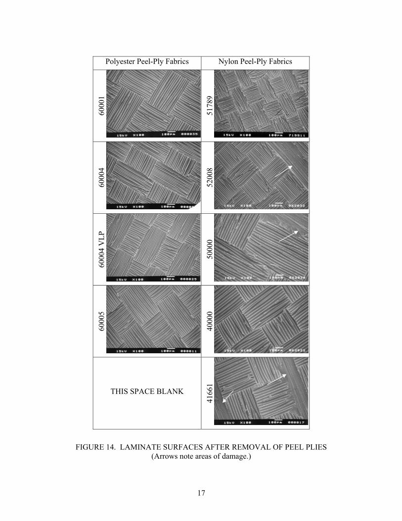
The texture of the peel-ply fabric directly controlled the laminate surface topography when the predominate mode of fracture during peel-ply removal was along the interface between the peel-ply filaments and the epoxy matrix (type 2 in figure 2). This was observed in all laminates fabricated with polyester peel plies, as shown in figure 9. During the cure cycle, the epoxy flowed around the filaments in the peel-ply fabric and subsequently gelled and cured. When the peel ply was removed, a negative of the peel-ply fabric was left in the epoxy matrix above the carbon fibers in the laminate. This is clearly illustrated by comparing mating surfaces of the peel plies in figure 3 and the laminate surfaces after peel-ply removal in figure 9. On the macroscopic scale, similar results were observed in laminates fabricated with PFG nylon peel plies 52008 and 40000 that were removed without observable damage to laminates. The PFG nylon peel plies with coarser weaves (50000 and 41661) adhered to the laminates during cure and upon removal, interlaminar fracture occurred and carbon fibers were removed from the laminate, as shown in figure 14. The peel plies removed from the laminates were also examined in the SEM and are shown in figure 15 where both the peel-ply filaments and the fracture epoxy matrix are visible. The filaments in the polyester peel plies appear similar to the filaments in the as-received peel plies shown in figure 3. The filaments in the nylon peel plies have a more tortured appearance; the surfaces are not clean and smooth, but rather ragged and torn. A higher-magnification view of the removed peel-ply filaments is shown in figure 16.
16
Polyester Peel-Ply Fabrics Nylon Peel-Ply Fabrics
6000
1
5178
9
6000
4
5200
8
6000
4 V
LP
5000
0
6000
5
4000
0
THIS SPACE BLANK
4166
1
FIGURE 14. LAMINATE SURFACES AFTER REMOVAL OF PEEL PLIES (Arrows note areas of damage.)
17

Polyester Peel-Ply Fabrics Nylon Peel-Ply Fabrics
6000
1
5178
9
6000
4
5200
8
6000
4 V
LP
5000
0
6000
5
4000
0
THIS SPACE BLANK
4166
1
FIGURE 15. PEEL PLIES AFTER REMOVAL FROM CURED LAMINATE (Arrows note damaged peel-ply filaments or carbon fibers from laminate surface.)
18

FIGURE 16. SCANNING ELECTRON MICROSCOPY IMAGE OF REMOVED PFG PEEL-PLY 60001 AND 41661 ILLUSTRATING DAMAGE TO PEEL-PLY FILAMENTS
IN THE LATTER The measured fracture energy, or strain energy release rate, GIC, of the bonded samples (averaged from the 10 tested samples from each peel ply) is presented in table 6 and figure 17 as a function of peel-ply material and weave (surface texture) and adhesive. The bond quality of laminates produced with nylon peel plies was very sensitive to the adhesive used. AF555 bonded well to the nylon prepared surfaces; where as MB1515-3 did not. This is reflected in both the GIC values and the mode of fracture shown in table 6. A dramatic decrease in fracture energy was observed when nylon-prepared surfaces were bonded with MB1515-3 and the fracture mode changed from cohesive (AF555) to adhesion (MB1515-3). Due to the difficulty in removing three of the five nylon peel plies from the laminates, there is insufficient data to draw conclusions on the effect of peel-ply surface texture using nylon peel plies. In the authors’ opinion, the effect of surface texture would be minor, if any, when the fracture is cohesive (within the adhesive layer). Surface texture may be more important when fracture occurs along the adhesive/laminate interface or between the lamina.
19

TABLE 6. SUMMARY OF AVERAGE (FROM 10 SAMPLES EACH) GIC DATA AND FAILURE MODE FOR LAMINATES PREPARED WITH VARIOUS PEEL PLIES AND
BONDED WITH AF555 AND MB1515-3
Specimen ID No.
GIC (J/m2)
Standard Deviation Failure Mode
40000 AF 745 75 Cohesive/Interlaminar 40000 MB 209 58 Adhesion 52008 AF 911 80 Cohesive/Interlaminar 52008 MB 122 15 Adhesion 60001 AF 910 35 Cohesive 60001 MB 812 35 Cohesive 60004 AF 956 202 Cohesive 60004 MB 856 37 Cohesive
60004 VLP AF 863 49 Cohesive 60004 VLP MB 914 140 Cohesive
60005 AF 904 38 Cohesive 60005 MB 657 277 Cohesive
910.7
745.0
955.5904.4
743.8
909.6
772.4
122.1
346.9
914.4
656.7
812.3
0.0
200.0
400.0
600.0
800.0
1000.0
1200.0
52008 40000 60004VLP
60004 60005 60001Wet
60001As Rec
60001 Dry
Peel Ply
GIC
(J/M
2 )
AF555
MB1515-3
FIGURE 17. AVERAGE GIC OF LAMINATES PREPARED WITH VARIOUS PEEL PLIES AND BONDED WITH AF555 OR MB1515-3
(Peel ply weaves coarsen from right to left.)
20

3.3 EFFECT OF PEEL-PLY MOISTURE. The effect of moisture in the 60001 polyester peel ply on GIC is presented in figure 18. All samples failed in a cohesive manner with respectable GIC values. The slightly higher value of GIC for laminates prepared with as-received 60001 peel ply has not been explained; this may be an experimental anomaly. Based on the cohesive fracture mode of all the samples and bracketing of the as-received GIC data by the wet and dry data, it appeared that peel-ply moisture had little if any effect on the bonding of the cured laminates with AF555. Other adhesives may be more sensitive to moisture than AF555, and other peel plies/laminate systems may be affected
FIGURE 18. AVERAGE G
by precure moisture in the peel ply.
AMINATES PREPARED WITH VARIOUS PEEL PLIES
.4 DETERMINATION OF SURFACE ENERGY BY CONTACT ANGLE
IC OF L
743.8
909.6
772.4
0.0
100.0
200.0
300.0
400.0
500.0
600.0
700.0
800.0
900.0
1000.0
60001 Wet 60001 As Rec 60001 Dry
Peel Ply
GIC
(J/
m2)
AND BONDED WITH AF555 OR MB1515-3
3 .
The effect of peel-ply material and texture on surface energy of the laminate surface was determined by examining the surface energies and wetting envelopes of the prepared surfaces. The known polar and dispersive components of the surface tension (γl
p and γld) of ethylene
glycol, deionized water, and DMSO [3] and the measured contact angles (θ) on each surface were used to construct Kaelble plots. The square of the slope of a linear fit of these plots is the polar component, γs
p, and the square of the intercept is the polar component, γsd, of the surface
energy of the laminate. The contact angle data obtained with glycerol was not used in constructing the Kaelble plots due to experimental difficulties associated with bubbles forming during the measurements. An example of a Kaelble plot is shown in figure 19 for BMS8-276 laminate prepared with PFG60001 peel ply. The results of contact angle measurements and calculated surface energies are summarized in table 7. The total surface energy γtot, is very similar between the surfaces, however there are significant differences in the dispersive and polar
21

components of the surface energy between the polyester and nylon peel-ply-prepared surfaces. The polyester peel-ply-prepared surfaces have a greater dispersive component, while the nylons have a larger polar component of surface energy.
FROM CONTACT ANGLE DATA ON BMS
DMSO
Ethylene Glycol
D.I. water
FIGURE 19. LINEAR KAELBLE PLOT FOR SURFACE ENERGY MEASUREMENT 8-276 LAMINATE PREPARED WITH
TABLE 7. CONTACT ANGLE M SURFACE ENERVARIETY OF FLUIDS MEASURED ON BMS8-276 LAMINATES PREPARED WITH
Peel Ply DI H2O
egrees) DMSO
(degrees) (degrees) (dγs
d
(mJ 2) γs
p
(mJ 2) γs total
(mJ 2)
PFG 60001 PEEL PLY
EASUREMENTS AND GIES FOR A
DIFFERENT PEEL PLIES
Ethylene Glycol
Gylcero
(dl
eg ees)r /m /m /m40000 23.0 24.0 47.0 51.3 12.9 27.6 61.5 51879 56.3 8.0 20.8 59.6 25.0 20.3 45.3 60001 63.4 6.8 27.0 56.1 30.3 13.7 44.0 60004 76.5 20.1 36.0 80.4 36.0 5.8 41.8 60004 VLP 71.5 19.0 45.8 76.7 33.6 7.3 40.9 60005 73.7 5.7 30.7 77.5 37.2 6.8 44.0
Wettability envelopes were lated from dispersiv pola pone f the ce nergy data in table 7. Fluids with surface energies inside the envelope will wet spontaneously
calcu the e and r com nts o surfaeand those outside the envelope will not. It is important for adhesives to wet out the substrate. Therefore, the wettability envelopes are a potential method to determine if a surface is suitable for bonding. The wettability envelopes for BMS8-276 laminates prepared with four polyester peel plies from PFG are shown in figure 20. There is some slight variation in the wettability envelopes, especially between the laminates prepared 60001 and the other three peel plies. The 60001-prepared surface has a greater polar component than the 60004, 60004VLP or 60005. The wettability envelopes for the laminate prepared with nylon peel plies (40000 and 51879) are
γsd = 30.3 mJ/m2, γ p=13.7 mJ/m2, γtot=44.0 mJ/m2
s
y = 5.4864x + 3.7178
0.0
2.0
4.0
6.0
8.0
10.0
12.0
14.0
16.0
0.0 0.5 1.0 1.5 2.0 2.5
sqrt(γ ld/γ l
p)
γl(1
+co
st)/
(2*
sqrt
(γlp
))
22

shown in figure 21. The laminate surface prepared with 40000 had a slightly greater polar component than the 51879-prepared surface, and the dispersive components were very similar. There were significant differences in the wettability envelopes between nylon- and polyester- prepared surfaces, as is evident in figure 22 where the envelopes for nylon 51879 and polyester 60001 are shown. For reference, typical values of surface energies for epoxy adhesives are shown by the shaded circle. The precise surface energies of the adhesives used in this study were not available from the literature or the manufacturers. Epoxy adhesives clearly fall within the envelope for polyester-prepared surfaces, but are on the boundary for the nylon surfaces. This may offer a possible explanation of the poor bonding with MB1515-3 on nylon peel-ply- prepared surfaces. The surface energy of MB1515-3 may be slightly outside that wettability envelope. It is important to note that contact angles by themselves were not sufficient to predict poor bonding with nylon-prepared surfaces. Nylon-prepared surfaces had lower contact angles with some fluids, including water, than polyester peel-ply prepared surfaces.
0
5
10
15
20
25
30
35
40
45
0 10 20 30
γlp (mJ/m2)
(mJ/
m 2
)
VLP600056000460001
D γ 1
FIGURE 20. WETTABILITY ENVELOPES FOR BMS8-276 LAMINATES PREPARED WITH PFG POLYESTER PEEL PLIES
(Left to right at the nose: 60004, 60004VLP, 60005, and 60001.)
23

24
0
5
10
15
20
25
30
35
40
0 10 20 30 40
γ lp(mJ/m2)
γld (m
J/m
2 )
5200640000
FIGURE 21. WETTABILITY ENVELOPES FOR BMS8-276 LAMINATES PREPARED THE PFG NYLON PEEL PLIES
FIGURE 22. WETTABILITY ENVELOPES FOR BMS8-276 LAMINATES PREPARED WITH PFG NYLON PEEL PLY 51879 AND POLYESTER PEEL-PLY 60001
(Left to right at the nose: 60001 and 51879.)
24

4. CONCLUSIONS.
The results of mechanical tests demonstrated a significant difference in bond quality when joints were prepared with varying peel ply materials and adhesives. All four weaves of uncoated polyester peel ply were easily removed from laminate surfaces after curing and created surfaces that bonded well using either adhesive. The surfaces that were generated were in all cases interfacial between the peel-ply fabric and the epoxy resin matrix. X-ray photoelectron spectroscopy (XPS) surface characterization of the surface generated with polyester peel did not detect any anomalous materials on the surface as were found on nylon. The bond failure was cohesive with average GIC values of 908 and 809 J/m2 for adhesives AF555 and MB1515-3, respectively. The 60001 Super Release Blue (siloxane-coated polyester) release films created very poor bonding surfaces with both adhesives, the result of the transfer of the peel-ply siloxane coating to the composite surface. Laminate surfaces prepared with nylon peel plies bonded well with AF555 (all GIC> 750J/m2; ohesive failure). Laminate surfaces prepared with nylon peel plies bonded poorly with
found using scanning electron mi ents of the removed nylon peel ply were shredded and small fiber fragments were found on the corresponding composite surface after peel-ply removal. MB1515-3 must have a chemical composition that does not bond well to epoxy surfaces contaminated with amides. AF555 is tolerant of some level of amide contamination. Nylon peel plies were more difficult to remove from the laminate and, in some cases, could not be removed without damaging the laminates. Finer weaves were easier to remove than coarser weaves. Single contact angle measurements and surface energies were not sufficient to predict bond quality. Nylon-prepared peel-ply surfaces had lower contact angles and hence higher surface energies, but produced unsatisfactory results when bonded with MB1515-3. Using wettability envelopes, epoxy adhesives were found to be on the border of acceptable wetting for these surfaces. Peel-ply texture or peel-ply moisture content had no significant effect on fracture energy or mode of failure for the adhesives and laminate system investigated. 5. REFERENCES
cMB1515-3 (average GIC< 165 J/m2; adhesion failure). An explanation for this difference was
croscopy and XPS. The filam
.
1. Hart-Smith, L., et al., “Some Observations on the Analysis of Inplane Matrix Failures in Fibrous Composite Laminates,” in 10th DoD/NASA/FAA Conference on Fibrous Composites in Structural Design, 1993.
2. ty o
A.J., Adhesion and Adhesives, Chapman and Hall, 1987.
Bardis, J. and Kedward, K., “Effects of Surface Preparation on the Long-Term Durabilif Adhesively Bonded Composite Joints,” DOT/FAA/AR-03/53, September 2004.
3. Kinloch,
25
4. Davis, M.J. and Bond, D., “Principles and Practices of Adhesive Bonded Structural Joints and Repairs,” International Journal of Adhesion and Adhesives, 19 (3): 1999, p. 91.
r Bonding,” International SAMPE Symposium and Exhibition, 50 (New Horizons for Materials and Processing
ffect of Absorbed Water in CFRP Composites on Adhesive Bonding,” International Journal of Adhesion and Adhesives, 16 (1), 1996, p. 21.
ing”, Douglas Service Magazine, First Quarter (12), 1984, p. 12.
5. Bossi, R., et al., “Composite Surface Preparation QA fo
Technologies), 2005. p. 2156. 6. Hart-Smith, L.J., “A Peel-Type Durability Test Coupon to Assess Interfaces in Bonded,
Co-Bonded, and Co-Cured Composite Structures,” International Journal of Adhesion and Adhesives, 19 (2-3), 1999 p. 181.
7. Armstrong, K/B., “E
8. Hart-Smith, L.J., et al., “Surface Preparation of Fibrous Composites for Adhesive
Bonding or Paint 9. Goldstein, J.I., et al., Scanning Electron Microscopy and X-Ray Microanalysis: A Text for
Biologists, Materials Scientists, and Geologists, 2 ed., New York: Plenum Press, 1992. 10. Kitazaki, Y. and Hata, T., “Surface-Chemical Criteria for Optimum Adhesion.3.
Variability of Critical Surface Tension(Gamma-C) and Its Choice,” Journal Of Adhesion, 4 (2), 1972, p. 123.
26