Embed Size (px)
Citation preview

Loughborough UniversityInstitutional Repository
The effect of laser remeltingon the surface chemistry of
Ti6al4V componentsfabricated by selective laser
melting
This item was submitted to Loughborough University's Institutional Repositoryby the/an author.
Citation: VAITHILINGAM, J. ... et al, 2016. The effect of laser remeltingon the surface chemistry of Ti6al4V components fabricated by selective lasermelting. Journal of Materials Processing Technology, 232, pp. 1 - 8.
Additional Information:
• This is an open access article published by Elsevier under the CC BYlicense (http://creativecommons.org/licenses/by/4.0/).
Metadata Record: https://dspace.lboro.ac.uk/2134/20397
Version: Published
Publisher: Elsevier / c© The Authors
Rights: This work is made available according to the conditions of the CreativeCommons Attribution 4.0 International (CC BY 4.0) licence. Full details of thislicence are available at: http://creativecommons.org/licenses/ by/4.0/
Please cite the published version.
Journal of Materials Processing Technology 232 (2016) 1–8
Contents lists available at ScienceDirect
Journal of Materials Processing Technology
jo ur nal ho me page: www.elsev ier .com/ locate / jmatprotec
The effect of laser remelting on the surface chemistry of Ti6al4Vcomponents fabricated by selective laser melting
Jayasheelan Vaithilingam a,∗, Ruth D. Goodridge a, Richard J.M. Hague a,Steven D.R. Christie b, Steve Edmondson c
a Additive Manufacturing and 3D Printing Research Group, School of Engineering The University of Nottingham, Nottingham, NG7 2RD, UKb Department of Chemistry, Loughborough University, Loughborough, LE11 3TU, UKc School of Materials, The University of Manchester, Manchester, M13 9PL, UK
a r t i c l e i n f o
Article history:Received 20 May 2015Received in revised form21 December 2015Accepted 21 January 2016Available online 24 January 2016
Keywords:Additive manufacturing3D-printingSelective laser meltingTi6Al4VSurface remeltingSurface chemistry
a b s t r a c t
Surface remelting/skin scanning of components is generally performed during the selective laser melting(SLM) process to improve the surface quality of a part. However, the chemical effects of surface remeltingare not well understood. In this study, cuboidal parts fabricated with and without laser remelting werecharacterised using scanning electron microscopy (SEM), surface profilometry and X-ray photoelectronspectrophotometry (XPS). The SEM images showed a low-amplitude undulating pattern was observedon both surfaces. The surface chemistries of the surface remelted/skin scanned (SK) and non-surfaceremelted/non-skin scanned (NSK) samples were observed to significantly differ in their elemental com-position. The thickness of the surface oxide layer of the SK surface was double that of the NSK surface.Also, the contribution of the major alloying elements, including titanium and aluminium, on the sur-face oxide layer varied for both NSK and SK surfaces. The surface chemistry of the NSK and SK surfacewas significantly different to a conventionally forged (CF) Ti6Al4V surface. The rate of decrease of oxidewith depth was in the order of CF > NSK > SK. Although surface remelting is useful in rendering improvedsurface quality, its impact on surface chemistry should be carefully considered.
© 2016 The Authors. Published by Elsevier B.V. This is an open access article under the CC BY license(http://creativecommons.org/licenses/by/4.0/).
1. Introduction
Selective laser melting (SLM) is a metal-based additive manu-facturing (AM) technique capable of fabricating parts directly fromthree dimensional (3D) computer models. Due to its increased geo-metrical freedom, the use of SLM to fabricate customised designswith complex internal and external structures is explored widelyfor various applications including in the automotive, aerospaceand biomedical industries (Gibson et al., 2010). In addition, SLMis widely regarded as an enabler of direct manufacture of end-useparts.
Although SLM has numerous advantages over conventionalmanufacturing such as moulding, die casting etc., the sur-face quality of a part produced by SLM is generally inferior.Vaithilingam et al. (2015) observed a surface roughness (Ra) of17.6 �m ± 2 �m for Ti6Al4V components fabricated using Ren-ishaw’s AM 250 SLM machine. Alrbaey et al. (2014) reported aRa value of 12.4 �m ± 3 �m for stainless steel components fabri-
∗ Corresponding author. Fax: +44 115 95 13948.E-mail address: [email protected] (J. Vaithilingam).
cated by employing the Renishaw’s SLM 125 machine. Meier andHaberland (2008) witnessed the surface quality of vertical wallsto be lower than the horizontal surfaces due to partially meltedparticles. Thus, in order to improve the surface quality of a SLMfabricated part, various post-processing techniques including sandblasting, machining, etching, electropolishing and plasma spray-ing, are employed. However, it is time consuming and not alwayspossible to use these techniques on certain complex parts. Thus,the opportunity to improve the surface quality of a part during theSLM process is favoured in order to enable the direct manufactureof a greater range of parts without the need for post-processing.
Optimisation of SLM process parameters (including hatch spac-ing, hatch distance, feed powder particle size) performed byYadroitsev and Smurov (2011) was observed to be useful in improv-ing surface quality to some degree; however, it did not render thedesired surface finish for a large number of applications. Kruth et al.(2010) proposed laser surface remelting as a potential solution toimprove surface quality during the SLM process. In this approach,the top/final surface of the part is remelted after the actual laserscanning which melts and fuses the material. By surface remelting,a significant reduction in the surface roughness (Ra) pattern from12 �m to 1.5 �m was observed. Yasa and Kruth (2011) have also
http://dx.doi.org/10.1016/j.jmatprotec.2016.01.0220924-0136/© 2016 The Authors. Published by Elsevier B.V. This is an open access article under the CC BY license (http://creativecommons.org/licenses/by/4.0/).

2 J. Vaithilingam et al. / Journal of Materials Processing Technology 232 (2016) 1–8
observed remelting the top layer to yield an improved surface fin-ish. Alrbaey et al. (2014) indicated that on laser remelting of 316Lstainless steel, the surface finish of SLM fabricated componentscan be improved by 80% than that of the initially fabricated sur-face (without surface remelting). Currently surface remelting, alsocalled skin scanning, is performed by many SLM users to enhancethe surface quality of SLM parts.
Surface remelting of the uppermost layer may be advanta-geous from a surface quality/finish point of view. However, surfaceremelting may affect the surface chemistry of the part. When a layerof a part fabricated by SLM is exposed to surface remelting, this willsignificantly increase the temperature and re-melt the previously-scanned layer. Since SLM is characterised by a rapid melting andcooling process, chemical transformations are possible dependingon the elements in the material, melting and cooling rate and buildatmosphere. Such chemical transformations may potentially dete-riorate the surface properties, including surface chemistry, of thepart. For example, when Kruth et al. (2010) processed Ti6Al4V bySLM, due to higher energy input and rapid solidification, formationof dark zones were witnessed. These dark zones were observed tocontain a high concentration of aluminium due to segregation.
For commercially pure titanium, there may not be this seg-regation effect since it does not contain other metals; however,alteration in the surface oxide thickness is possible due to the rapidheating and cooling cycles in the presence of oxygen. Ti6Al4V ispreferred in various applications because it displays enhanced cor-rosion resistance due to the presence of a stable TiO2 film at highconcentration on the surface (Warnke et al., 2009). Segregation ofaluminium might alter this oxide layer and reduce the concentra-tion of titanium oxide. This may potentially reduce the corrosionresistance and lead to failure of the part.
There is no previous literature that has investigated the effect oflaser remelting of SLM produced parts on its surface chemistry (inthe first few atomic layers) in detail. Hence in this study, Ti6Al4V,a grade 5 titanium alloy, was used to fabricate parts with skin scan(SK) and without skin scan (NSK) by SLM and the surface chemistryof these parts was examined.
2. Materials and methods
2.1. Material
Plasma atomised Ti6Al4V powder was purchased from LPWTechnology Ltd., UK. The particle size (Dv 50, the particle size belowwhich 50% of the sample volume is represented) was 33.2 �m.A conventionally forged (CF) Ti6Al4V plate was purchased fromTIMET UK Ltd., UK. The CF sample was used to study the differencesin surface chemistry between SLM fabricated NSK and SK surfacesand the CF surface. Solvents including dichloromethane, methanoland ethanol were purchased from Sigma Aldrich, UK.
2.2. Methods
2.2.1. CAD modelCuboidal parts with the dimensions of 10 mm × 10 mm × 5 mm
were designed using Magics 14.1 (Materialise) software and savedin a STL file format. The STL file was then sliced with 50 �m layerthickness. This design was then replicated to fabricate the requirednumber of samples.
2.2.2. Selective laser meltingThe cubical parts were fabricated in a Renishaw AM 250 machine
using Ti6Al4V powder. The AM 250 machine was equipped with afibre modulated pulse laser with a maximum power of 200 W andwavelength (�) of 1070 nm. The AM 250 machine consisted of ahopper, a wiper, an elevator that lowered the substrate to adjust the
Table 1Process parameters used fabricate non-skin scanned (NSK) and skin scanned (SK)Ti6Al4V surfaces in an SLM.
Standard No skin scan (NSK) Skin scan (SK)
Laser power P (W) 200 200Hatch spacing (�m) 100 100Point distance (�m) 50 50Exposure time (�s) 220 220Layer thickness (�m) 50 50Scan strategy Meander MeanderBuild plate temperature (◦C) 80 80No. of shell scan 1 2
layer thickness and a lens that focused the laser (200 W maximum)to the build area (250 × 250 × 300 mm). Before SLM, the Ti6Al4Vpowder from which the part was to be fabricated was spread overthe build platform from the hopper to a pre-defined layer thickness.After the layer had been spread, the laser beam scanned and fusedthe powder in the areas specified by the layer of the CAD file.
Previously optimised SLM process parameters used for the studyare tabulated in Table 1. As can be observed from the table, the onlychange in the process parameters between the NSK and SK was theskin scanning. A multi-directional meander scan strategy was usedwhere the laser scan direction was rotated by 67◦ for each layer toreduce the residual stress. The components were built on a Ti6Al4Vmetal substrate preheated to 80 ◦C. The build chamber was filledwith argon gas to maintain an inert atmosphere. The temperature ofthe build chamber during the process was measured to be 34–36 ◦C.
2.2.3. Sample preparationThe SLM fabricated samples were removed from the substrate
and sonicated in dichloromethane (DCM), methanol, ethanol anddeionised water for 10 min each to remove loosely bound Ti6Al4Vparticles and other surface contaminants. The substrates were thendried using compressed air before surface characterisation. The CFsample was polished using a series of silicon carbide grits and dia-mond pastes. The polished samples were cleaned as above beforesurface characterisation.
2.2.4. Surface characterisationSurface morphologyA Phillips (PW 6800/70) scanning electron microscope (SEM)
was used to obtain the surface morphology of SLM fabricatedTi6Al4V surfaces. SEM was operated at a power of 20 kV and imageswere obtained at various magnifications.
Surface roughnessSurface roughness patterns of the NSK and SK surfaces were
obtained using an Alicona InfiniteFocus® optical 3D measure-ment device. The Ra value was calculated by averaging the valuesobtained for five different samples from 175 �m2 of each sample.The reported values are the mean ± standard error of the mean.
Surface chemistryA Thermo Scientific K-Alpha X-ray photoelectron spectroscopy
(XPS) was used to obtain the surface chemistry of the Ti6Al4V sur-face. XPS probing of the Ti6Al4V metal surface was performed on arandom selection of areas which were considered to have accept-able flatness. Depth profiling was performed to study the elementaldistribution and the oxide layer thickness of the SLM fabricatedTi6Al4V surface. Depth profiles were obtained by sputtering thespecimen at a rate of approximately 1.35 Angstrom/sec (for tita-nium) using an argon ion gun. The probing spot size used to obtainthe measurement was 400 �m. Aluminium (Al) K� monochro-mated radiation at 1486.6 eV was used and photoelectrons werecollected at a take-off angle of 90◦. Survey spectra were collected ata pass energy of 100 eV in a constant energy analyser mode. Highresolution spectra were obtained at a pass energy of 20 eV. Peak
J. Vaithilingam et al. / Journal of Materials Processing Technology 232 (2016) 1–8 3
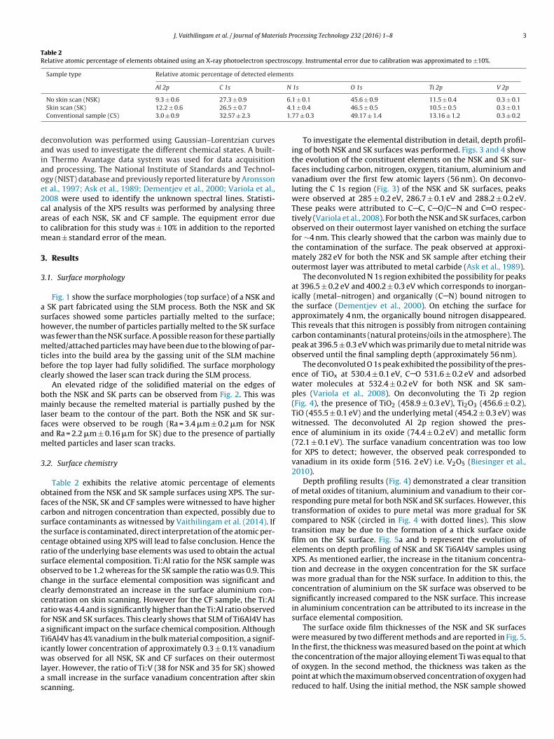
Table 2Relative atomic percentage of elements obtained using an X-ray photoelectron spectroscopy. Instrumental error due to calibration was approximated to ±10%.
Sample type Relative atomic percentage of detected elements
Al 2p C 1s N 1s O 1s Ti 2p V 2p
No skin scan (NSK) 9.3 ± 0.6 27.3 ± 0.9 6.1 ± 0.1 45.6 ± 0.9 11.5 ± 0.4 0.3 ± 0.1Skin scan (SK) 12.2 ± 0.6 26.5 ± 0.7 4.1 ± 0.4 46.5 ± 0.5 10.5 ± 0.5 0.3 ± 0.1Conventional sample (CS) 3.0 ± 0.9 32.57 ± 2.3 1.77 ± 0.3 49.17 ± 1.4 13.16 ± 1.2 0.3 ± 0.2
deconvolution was performed using Gaussian–Lorentzian curvesand was used to investigate the different chemical states. A built-in Thermo Avantage data system was used for data acquisitionand processing. The National Institute of Standards and Technol-ogy (NIST) database and previously reported literature by Aronssonet al., 1997; Ask et al., 1989; Dementjev et al., 2000; Variola et al.,2008 were used to identify the unknown spectral lines. Statisti-cal analysis of the XPS results was performed by analysing threeareas of each NSK, SK and CF sample. The equipment error dueto calibration for this study was ± 10% in addition to the reportedmean ± standard error of the mean.
3. Results
3.1. Surface morphology
Fig. 1 show the surface morphologies (top surface) of a NSK anda SK part fabricated using the SLM process. Both the NSK and SKsurfaces showed some particles partially melted to the surface;however, the number of particles partially melted to the SK surfacewas fewer than the NSK surface. A possible reason for these partiallymelted/attached particles may have been due to the blowing of par-ticles into the build area by the gassing unit of the SLM machinebefore the top layer had fully solidified. The surface morphologyclearly showed the laser scan track during the SLM process.
An elevated ridge of the solidified material on the edges ofboth the NSK and SK parts can be observed from Fig. 2. This wasmainly because the remelted material is partially pushed by thelaser beam to the contour of the part. Both the NSK and SK sur-faces were observed to be rough (Ra = 3.4 �m ± 0.2 �m for NSKand Ra = 2.2 �m ± 0.16 �m for SK) due to the presence of partiallymelted particles and laser scan tracks.
3.2. Surface chemistry
Table 2 exhibits the relative atomic percentage of elementsobtained from the NSK and SK sample surfaces using XPS. The sur-faces of the NSK, SK and CF samples were witnessed to have highercarbon and nitrogen concentration than expected, possibly due tosurface contaminants as witnessed by Vaithilingam et al. (2014). Ifthe surface is contaminated, direct interpretation of the atomic per-centage obtained using XPS will lead to false conclusion. Hence theratio of the underlying base elements was used to obtain the actualsurface elemental composition. Ti:Al ratio for the NSK sample wasobserved to be 1.2 whereas for the SK sample the ratio was 0.9. Thischange in the surface elemental composition was significant andclearly demonstrated an increase in the surface aluminium con-centration on skin scanning. However for the CF sample, the Ti:Alratio was 4.4 and is significantly higher than the Ti:Al ratio observedfor NSK and SK surfaces. This clearly shows that SLM of Ti6Al4V hasa significant impact on the surface chemical composition. AlthoughTi6Al4V has 4% vanadium in the bulk material composition, a signif-icantly lower concentration of approximately 0.3 ± 0.1% vanadiumwas observed for all NSK, SK and CF surfaces on their outermostlayer. However, the ratio of Ti:V (38 for NSK and 35 for SK) showeda small increase in the surface vanadium concentration after skinscanning.
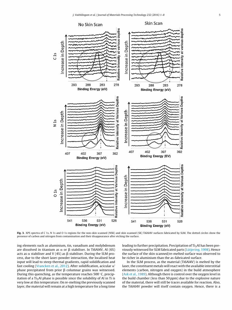
To investigate the elemental distribution in detail, depth profil-ing of both NSK and SK surfaces was performed. Figs. 3 and 4 showthe evolution of the constituent elements on the NSK and SK sur-faces including carbon, nitrogen, oxygen, titanium, aluminium andvanadium over the first few atomic layers (56 nm). On deconvo-luting the C 1s region (Fig. 3) of the NSK and SK surfaces, peakswere observed at 285 ± 0.2 eV, 286.7 ± 0.1 eV and 288.2 ± 0.2 eV.These peaks were attributed to C C, C O/C N and C O respec-tively (Variola et al., 2008). For both the NSK and SK surfaces, carbonobserved on their outermost layer vanished on etching the surfacefor ∼4 nm. This clearly showed that the carbon was mainly due tothe contamination of the surface. The peak observed at approxi-mately 282 eV for both the NSK and SK sample after etching theiroutermost layer was attributed to metal carbide (Ask et al., 1989).
The deconvoluted N 1s region exhibited the possibility for peaksat 396.5 ± 0.2 eV and 400.2 ± 0.3 eV which corresponds to inorgan-ically (metal–nitrogen) and organically (C N) bound nitrogen tothe surface (Dementjev et al., 2000). On etching the surface forapproximately 4 nm, the organically bound nitrogen disappeared.This reveals that this nitrogen is possibly from nitrogen containingcarbon contaminants (natural proteins/oils in the atmosphere). Thepeak at 396.5 ± 0.3 eV which was primarily due to metal nitride wasobserved until the final sampling depth (approximately 56 nm).
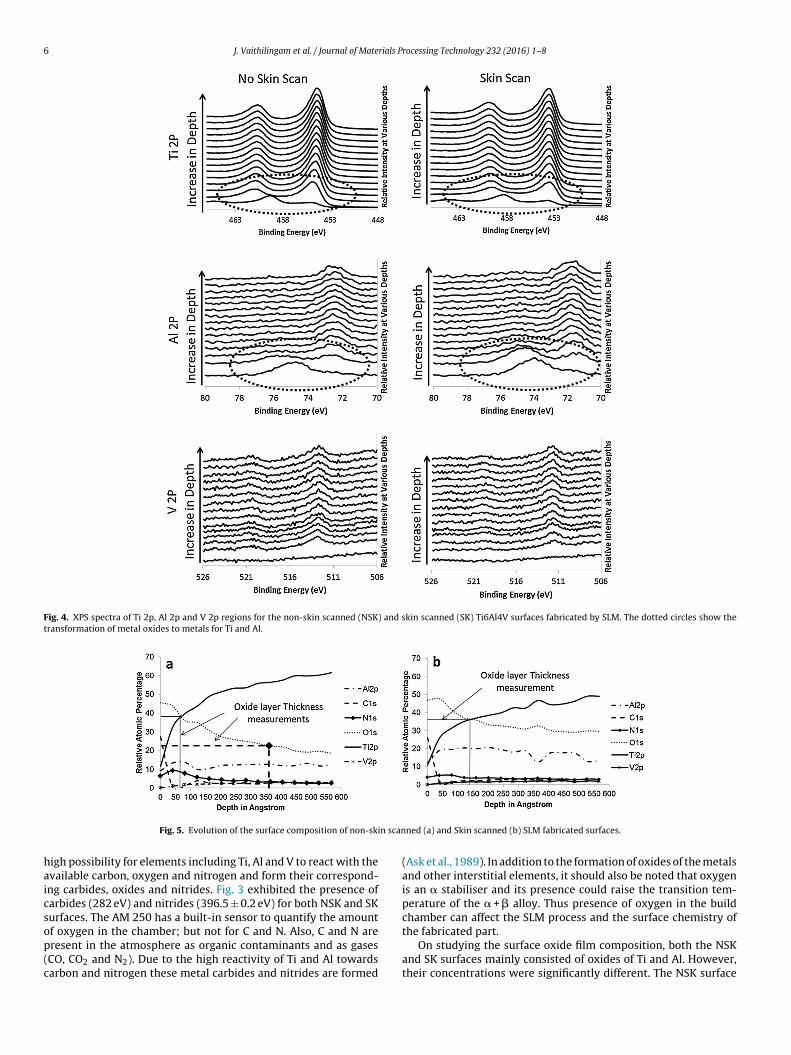
The deconvoluted O 1s peak exhibited the possibility of the pres-ence of TiOx at 530.4 ± 0.1 eV, C O 531.6 ± 0.2 eV and adsorbedwater molecules at 532.4 ± 0.2 eV for both NSK and SK sam-ples (Variola et al., 2008). On deconvoluting the Ti 2p region(Fig. 4), the presence of TiO2 (458.9 ± 0.3 eV), Ti2O3 (456.6 ± 0.2),TiO (455.5 ± 0.1 eV) and the underlying metal (454.2 ± 0.3 eV) waswitnessed. The deconvoluted Al 2p region showed the pres-ence of aluminium in its oxide (74.4 ± 0.2 eV) and metallic form(72.1 ± 0.1 eV). The surface vanadium concentration was too lowfor XPS to detect; however, the observed peak corresponded tovanadium in its oxide form (516. 2 eV) i.e. V2O5 (Biesinger et al.,2010).
Depth profiling results (Fig. 4) demonstrated a clear transitionof metal oxides of titanium, aluminium and vanadium to their cor-responding pure metal for both NSK and SK surfaces. However, thistransformation of oxides to pure metal was more gradual for SKcompared to NSK (circled in Fig. 4 with dotted lines). This slowtransition may be due to the formation of a thick surface oxidefilm on the SK surface. Fig. 5a and b represent the evolution ofelements on depth profiling of NSK and SK Ti6Al4V samples usingXPS. As mentioned earlier, the increase in the titanium concentra-tion and decrease in the oxygen concentration for the SK surfacewas more gradual than for the NSK surface. In addition to this, theconcentration of aluminium on the SK surface was observed to besignificantly increased compared to the NSK surface. This increasein aluminium concentration can be attributed to its increase in thesurface elemental composition.
The surface oxide film thicknesses of the NSK and SK surfaceswere measured by two different methods and are reported in Fig. 5.In the first, the thickness was measured based on the point at whichthe concentration of the major alloying element Ti was equal to thatof oxygen. In the second method, the thickness was taken as thepoint at which the maximum observed concentration of oxygen hadreduced to half. Using the initial method, the NSK sample showed

4 J. Vaithilingam et al. / Journal of Materials Processing Technology 232 (2016) 1–8
Fig. 1. Surface morphology of non-skin scanned and skin scanned Ti6Al4V SLM surfaces showing the laser scan tracks. The working distance for (a) (27.7 mm) and (b)(27.9 mm) are slightly different due to the presence of Ti6Al4V particles.
Fig. 2. Surface morphology of a non-skin scanned (a) and skin scanned (b) Ti6Al4V part fabricated by SLM.
a thickness of approximately 7 nm whereas the SK part showedapproximately 14 nm which was nearly double that of the NSK’soxide layer thickness. In method 2, for NSK, the initially observedmaximum detected O concentration of 46% reduced to 23% at nearly35 nm; whereas for the SK surface, the initial maximum O concen-tration of nearly 47% did not reduce to half until the sampling depthof 56 nm. Both methods revealed that the thickness of the surfaceoxide film was higher for the SK surface than the NSK surface.
The ratio of the metals to oxide (Ti + Al + V:O) of the NSK, SKand CF samples as a function of depth were compared to study thespatial transition between surface metal oxide and the bulk, and areplotted in Fig. 6. Although the surfaces (depth = 0) are very similar,clear and significant differences in the depth distribution of theoxides for the SLM fabricated NSK, SK surfaces and the CF samplewere observed. The rate of decrease of oxide with depth was in theorder of CF > NSK > SK. The possible reasons for the varied elementaldistribution and surface oxide transition are discussed below.
4. Discussion
In this study, both the NSK and SK parts fabricated using theAM 250 were observed to be slightly rough due to the presence ofpartially melted particles. In agreement with Meier and Haberland(2008), this study also observed the surface quality of the verti-cal surfaces to be inferior compared to the top/horizontal surface.Particles were also observed on the vertical sides of the cuboidalsamples (other than top surface) and were primarily due to the par-tial melting of particles to the build surface. However, the partiallysintered particles observed on the top horizontal surface mightbe due to the blowing of metal particles into the laser meltedzones by the argon gas flow in the build chamber. Particles mayalso flow from the powder bed to the build due to small vibra-tions/movement of the wiper that may occur during the process.
Apart from the partially melted particles, laser scan tracks wereclearly visible in the surface morphology of the NSK and especiallyon the SK surfaces. Since the SK surfaces were scanned by the lasertwice, the scan tracks were more clearly visible. The SK surfacewas relatively smooth compared to the NSK surface since unevenmorphologies were smoothened due to laser remelting. However,it should also be noted that as a result of remelting, laser scantracks were witnessed and this might potentially affect the sur-face profile. The obtained Ra value for SK surfaces in this study wascomparable to the previously reported value of 1.5 �m for SK sur-face by Yasa and Kruth (2011). The reduction in the Ra value from3.4 �m ± 0.2 �m to 2.2 �m ± 0.16 after remelting clearly shows animprovement in the surface quality. Thus the surface remelting isuseful to enhance the surface quality.
Kruth et al. (2010) suggested the use of skin scanning (remelt-ing) for an improved surface quality and mechanical properties.However, the surface chemistry of such skin scanned surfaces hasnot been discussed. This study witnessed a high concentration ofaluminium in the SK surface compared to the NSK surface. Althoughthe Ti6Al4V alloy has only 6% Al in the bulk, more than 10% wasobserved on the NSK surface and over 15% of Al on the SK surface.However, only 3% was witnessed for the CF surface. One of the pos-sible reasons for the increase in the concentration of Al on the NSKand SK surface than the actual alloy concentration may possibly dueto rapid melting and solidification during the SLM process (Kruthet al., 2010).
The superior mechanical property of the titanium alloys com-pared to the commercially pure titanium (cpTi) is due to its phasecomposition. At room temperature, the cpTi is composed of ahexagonal closed-pack (hcp) � phase. However, when the temper-ature is raised to 882 ◦C (� transition temperature), the cpTi willundergo an allotropic transformation from hcp � phase to a bodycentred cubic (bcc) � phase (Kruth et al., 2010). Hence to alter the�-� transition temperature and obtain �+� alloy of titanium, alloy-
J. Vaithilingam et al. / Journal of Materials Processing Technology 232 (2016) 1–8 5
Fig. 3. XPS spectra of C 1s, N 1s and O 1s regions for the non-skin scanned (NSK) and skin scanned (SK) Ti6Al4V surfaces fabricated by SLM. The dotted circles show thepresence of carbon and nitrogen from contamination and their disappearance after etching the surface.
ing elements such as aluminium, tin, vanadium and molybdenumare dissolved in titanium as � or � stabiliser. In Ti6Al4V, Al (6%)acts as � stabiliser and V (4%) as � stabiliser. During the SLM pro-cess, due to the short laser-powder interaction, the localised heatinput will lead to steep thermal gradients, rapid solidification andfast cooling (Vrancken et al., 2012). After solidification, acicular �’phase precipitated from prior � columnar grains was witnessed.During this quenching, as the temperature reaches 500 ◦C, precip-itation of a Ti3Al phase is possible since the solubility of Al in Ti isvery low at this temperature. On re-melting the previously scannedlayer, the material will remain at a high temperature for a long time
leading to further precipitation. Precipitation of Ti3Al has been pre-viously witnessed for SLM fabricated parts (Lütjering, 1998). Hencethe surface of the skin scanned/re-melted surface was observed tobe richer in aluminium than the as-fabricated surface.
In the SLM process, as the material (Ti6Al4V) is melted by thelaser, the constituent metals will react with the available interstitialelements (carbon, nitrogen and oxygen) in the build atmosphere(Ask et al., 1989). Although there is control over the oxygen level inthe build chamber (less than 50 ppm) due to the explosive natureof the material, there will still be traces available for reaction. Also,the Ti6Al4V powder will itself contain oxygen. Hence, there is a
6 J. Vaithilingam et al. / Journal of Materials Processing Technology 232 (2016) 1–8
Fig. 4. XPS spectra of Ti 2p, Al 2p and V 2p regions for the non-skin scanned (NSK) and skin scanned (SK) Ti6Al4V surfaces fabricated by SLM. The dotted circles show thetransformation of metal oxides to metals for Ti and Al.
Fig. 5. Evolution of the surface composition of non-skin scanned (a) and Skin scanned (b) SLM fabricated surfaces.
high possibility for elements including Ti, Al and V to react with theavailable carbon, oxygen and nitrogen and form their correspond-ing carbides, oxides and nitrides. Fig. 3 exhibited the presence ofcarbides (282 eV) and nitrides (396.5 ± 0.2 eV) for both NSK and SKsurfaces. The AM 250 has a built-in sensor to quantify the amountof oxygen in the chamber; but not for C and N. Also, C and N arepresent in the atmosphere as organic contaminants and as gases(CO, CO2 and N2). Due to the high reactivity of Ti and Al towardscarbon and nitrogen these metal carbides and nitrides are formed
(Ask et al., 1989). In addition to the formation of oxides of the metalsand other interstitial elements, it should also be noted that oxygenis an � stabiliser and its presence could raise the transition tem-perature of the � + � alloy. Thus presence of oxygen in the buildchamber can affect the SLM process and the surface chemistry ofthe fabricated part.
On studying the surface oxide film composition, both the NSKand SK surfaces mainly consisted of oxides of Ti and Al. However,their concentrations were significantly different. The NSK surface

J. Vaithilingam et al. / Journal of Materials Processing Technology 232 (2016) 1–8 7
Fig. 6. A comparison of the oxide depth profile for the NSK, SK and CF Ti6Al4Vsamples.
rendered a surface oxide film rich in titanium whereas the SKsurface rendered an oxide film rich in aluminium. Also the deter-mined thickness of the oxide film was higher for the SK surfacecompared to the NSK surface. The main reason for the formationof a thick oxide layer on the SK surface is due to remelting or skinscanning. During SK, as the surface was melted twice, there was ahigh possibility for the penetration of oxygen from the build atmo-sphere further into the surface, thus leading to the formation of athick oxide layer. Also, due to SK, there was a high possibility forthe precipitation of Al (due to rapid heating and cooling cycles) onthe surface, thus leading to an increased aluminium concentrationon the SK surface. Fig. 6 clearly depicts the rate of decrease of oxidewith depth to be in the order of CF > NSK > SK. One of the major rea-sons for the more gradual transition of the metal oxides to metal inNSK and SK surfaces is due to the formation of thick surface oxidelayer. Also, when the NSK surface was remelted, a further reductionin oxide thickness can witnessed. This clearly indicated that SLMprocessing of Ti6Al4V is the major reason for producing a thickersurface oxide layer than the CF sample; however, surface remeltingfurther increases the oxide layer thickness. It should be noted thaton remelting, the laser scan tracks might have slightly increasedthe roughness of the SK surface and since XPS is highly sensitive torough surfaces, there is the possibility for the results to be affectedby this to a small level (Gunter et al., 1997; Martín-Concepción et al.,2004).
Ti6Al4V alloy is preferred for various applications because ofthe surface TiO2 film. For automotive applications, the presence ofthis passive TiO2 film offers high corrosion resistance. In biomedi-cal applications, the presence of corrosion resistant TiO2 film offershigh biocompatibility. Also, SLM is considered as one of the viableprocesses to make customised metallic parts with complex struc-tures. The use of SLM to fabricate such intricate parts will be limitedif the process affects the surface chemical composition. Surfacechemistry plays a pivotal role in determining the surface proper-ties of a material (Mani et al., 2007). Small changes in the chemicalcomposition may cause catastrophic loss of ductility and corro-sion resistance (Manivasagam et al., 2010). Corrosion resistanceis dependent on the surface oxide layer thickness. In general, thethicker the oxide layer is, the higher is the corrosion resistance. Sur-face oxide layers act as a barrier and prevent the release of metalions from the bulk material. The corrosion resistance of the SLMfabricated Ti6Al4V has been discussed in literature (Chang and Lee,2002). Vandenbroucke and Kruth (2007) reported that the corro-sion resistance offered by the SLM fabricated Ti6Al4V parts satisfiedthe requirements for medical application. However, long-term useof Ti6Al4V implants for medical applications were observed to pro-duce cytotoxic effects due to the release of Al and V ions (Eliaset al., 2008). Since the SLM fabricated parts in this study producedsurfaces with a higher concentration of aluminium than the bulk
material, it is crucial to understand how the process conditionsmight affect the surface properties. Dai et al. (2015) reported thatthe existence of relatively large amounts of acicular �′-Ti phasecompared to the �-Ti phase in an SLM sample as a main reasonfor poor corrosion resistance. The present study also observed ahigher concentration of Al, the � stabilizer on the surface. This sug-gests that the presence of high concentration of Al on the surfacewill affect the corrosion resistance of SLM fabricated Ti6Al4V.
In addition to improving the surface quality, surface-remeltingis also performed to improve the density of a fabricated part (Yasaand Kruth, 2011). This is achieved by remelting the previously laser-scanned layer to form an even surface. When the surface is even,the distribution of powder to build the next layer will be morehomogenous and will reduce the entrapment of air. Hence, thereis a high possibility to reduce pores and improve the density ofthe part. However, changes in the surface oxide composition mayalter the wettability and could possibly result in balling phenomena(splitting-up of melt pool into tiny spheres/entities) and delamina-tion of successive layers. Also precipitation of aluminium due to theimpact of laser power may also affect the mechanical properties ofSLM fabricated Ti6Al4V components. Thus where a strict control ofthe surface chemistry is required, the processing parameters mustbe chosen appropriately.
5. Conclusions
• The surface chemistry of the SLM fabricated NSK and SK surfaceswere significantly different to the conventionally forged surface.
• Selective remelting/skin scanning of the final layer may beadvantageous in terms of rendering an improved surface finish.However, it should be noted that it alters the surface chemicalcomposition and the surface oxide layer.
• The surface oxide film of the skin scanned surface was enrichedwith oxides of aluminium whereas the surface oxide film ofnon-skin scanned surface was enriched with oxides of titanium.Also the concentration of vanadium on the skin scanned surfaceincreased compared to the non-skin scanned surface.
• Since selective remelting alters the surface chemical composi-tion by increasing aluminium and vanadium concentration onthe surface, corrosion resistance and biocompatibility of thesecomponents may be significantly reduced.
• Further studies on the oxide layer thickness and corrosion resis-tance of the selective remelted and non-remelted parts would bebeneficial to enable improved understanding.
Acknowledgement
This work was supported by the Engineering and Physical Sci-ences Research Council(EPSRC; UK) under grant EP/I033335/2.
References
Alrbaey, K., Wimpenny, D., Tosi, R., Manning, W., Moroz, A., 2014. J. Mater. Eng.Perform. 23, 2139–2148.
Aronsson, B.O., Lausmaa, J., Kasemo, B., 1997. J. Biomed. Mater. Res. 35, 49–73.Ask, M., Lausmaa, J., Kasemo, B., 1989. Appl. Surf. Sci. 35, 283–301.Biesinger, M.C., Lau, L.W.M., Gerson, A.R., Smart, R.S.C., 2010. Appl. Surf. Sci. 257,
887–898.Chang, E., Lee, T.M., 2002. Biomaterials 23, 2917–2925.Dai, N., Zhang, L.-C., Zhang, J., Chen, Q., Wu, M., 2015. Corros. Sci., 4–9.Dementjev, A.P., Graaf, A., De Sanden Van De, M.C.M., Maslakov, K.I., 2000.
Diamond Relat. Mater. 9, 1904–1907.Elias, C.N., Lima, J.H.C., Valiev, R., Meyers, M., 2008. J. Miner. Met. Mater. Soc.,
46–49.Gibson, I., Rosen, D.W., Stucker, B., 2010. Additive Manufacturing Technologies.
Springer, US, Boston, MA.Gunter, P.L., Gijzeman, O.L., Niemantsverdriet, J., 1997. Appl. Surf. Sci. 115,
342–346.

8 J. Vaithilingam et al. / Journal of Materials Processing Technology 232 (2016) 1–8
Kruth, J., Badrossamay, M., Yasa, E., Deckers, J., Thijs L., Van Humbeeck, J., 2010.Part and material properties in selective laser melting of metals in: 16thInternational Symposium on Electromachining, 1–12.
Lütjering, G., 1998. Mater. Sci. Eng. A 243, 32–45.Mani, G., Feldman, M.D., Patel, D., Agrawal, C.M., 2007. Biomaterials 28, 1689–1710.Manivasagam, G., Dhinasekaran, D., Rajamanickam, A., 2010. Recent Patents
Corros. Sci. 2, 40–54.Martín-Concepción, I., Yubero, F., Espinós, J.P., Tougaard, S., 2004. Surf. Interface
Anal. 36, 788–792.Meier, H., Haberland, C., 2008. Materwiss. Werksttech. 39, 665–670.Vaithilingam, J., Kilsby, S., Goodridge, R.D., Christie, S.D.R., Edmondson, S., Hague,
R.J.M., 2014. Appl. Surf. Sci. 314, 642–654.
Vaithilingam, J., Kilsby, S., Goodridge, R.D., Christie, S.D.R., Edmondson, S., Hague,R.J.M., 2015. Mater. Sci. Eng. C 46, 52–61.
Vandenbroucke, B., Kruth, J.-P., 2007. Rapid Prototyp. J. 13, 196–203.Variola, F., Yi, J.-H., Richert, L., Wuest, J.D., Rosei, F., Nanci, A., 2008. Biomaterials 29,
1285–1298.Vrancken, B., Thijs, L., Kruth, J.-P., Van Humbeeck, J., 2012. J. Alloys Compd. 541,
177–185.Warnke, P.H., Douglas, T., Wollny, P., Sherry, E., Steiner, M., Galonska, S.,
Sivananthan, S., 2009. Tissue Eng. Part C 15, 115–124.Yadroitsev, I., Smurov, I., 2011. Phys. Procedia 12, 264–270.Yasa, E., Kruth, J., 2011. Adv. Prod. Eng. Manag. 6, 259–270.


![Laser Melting of and Matrix Composites: Recent Progress ......laser melting [15], (c) flange fabricated by laser additive manufacturing of Inconel 718 [16], and (d) aircraft bracket](https://img.dokumen.tips/doc/110x75/612273f76a45b223526528fc/laser-melting-of-and-matrix-composites-recent-progress-laser-melting-15.jpg)