Embed Size (px)
Citation preview

THE EFFECT OF AGEING ON THE SPOT WELD STRENGTH OF AHSS AND THE CONSEQUENCES FOR TESTING PROCEDURESR12
Welding in the World, Vol. 54, n° 1/2, 2010 – Peer-reviewed Section
THE EFFECT OF AGEING ON THE SPOT WELD STRENGTH OF AHSS AND THE CONSEQUENCES
FOR TESTING PROCEDURES
S. Smith N.J. den Uijl T. Okada T. van der Veldt M. Uchihara K. Fukui
ABSTRACT
Market trends within the automotive industry are leading to an ever-increasing use of high-strength and advanced high-strength steels (AHSS). The attraction of these materials is the advantage of excellent formability, combined with increasingly high tensile strength. It is a well-known fact that weld performance can be an issue with AHSS, where susceptible weld microstructures can lead to low strengths and undesirable failure modes. Much research has been conducted and published on this subject. A less well-documented effect in the weld performance of AHSS is ‘ageing’, whereby a weld exhibits poor mechanical performance immediately after welding, but after a certain period of time, the weld properties improve signifi cantly. In the Corus – SMI research cooperation, this ‘ageing’ effect was fi rst observed in weld samples in 2004, since this time ageing has been a major topic of combined research. This presentation is a summary of the Corus – SMI weld ageing study, highlighting the major issues and characteristics of the effect: the infl uence of process parameters, the susceptible alloying systems and the possible mechanisms that can cause ageing of the weld. The ‘ageing’ effect has serious implications for standardized testing procedures, where the timescale between welding and testing is not specifi ed, ageing can have a huge infl uence on the welding results obtained in ageing susceptible materials. The fi nal aspect of this report is to consider the consequences of ageing for weld testing procedures.
IIW-Thesaurus keywords: Ageing; Austenite; Automobile engineering; Brittle fracture; Cruciform joints; Ductile fracture; Fractures; Gases; High strength steels; Hydrogen; Martensite; Mechanical properties; Peel strength; Refer-ence lists; Resistance spot welding; Resistance welding; Steels; Strength.
Mr. Sullivan SMITH ([email protected]), Mr. Nick J. DEN UIJL ([email protected]) and Dr. Tony VAN DER VELDT ([email protected]) are with Corus RD&T, IJmuiden (The Netherlands). Mr. Torhu OKADA ([email protected]) and Mr. Masato UCHIHARA ([email protected]) are both with Sumitomo Metal Industries, Hyogo, (Japan). Dr. Kiyoyuki FUKUI ([email protected]) is with Sumitomo Metal Industries, Tokyo (Japan).
Doc. IIW-1976-08 (ex-doc. III-1489r1-08), recom-mended for publication by Commission III “Resistance Welding, Solid State Welding and Allied Joining Proc-esses.”
1 INTRODUCTION
In recent years, two trends have been dominating design and manufacturing in the automotive industry. On the one hand, there is a trend to reduce the weight of vehicles, driven by the desire to decrease fuel consump-tion and the release of greenhouse gases. On the other hand, there is a trend to improve the structural rigidity of vehicles (especially the crash performance), motivated by regulations and consumer demands. Advanced High-Strength Steels (AHSS) offer the automotive industry the options to achieve both goals [1, 2].
AHSS combine high strength with good formability. This is achieved by balanced chemical composition and thermo-mechanical treatment during production of these

THE EFFECT OF AGEING ON THE SPOT WELD STRENGTH OF AHSS AND THE CONSEQUENCES FOR TESTING PROCEDURES R13
Welding in the World, Vol. 54, n° 1/2, 2010 – Peer-reviewed Section
steels. However, certain issues have been reported con-cerning the weldability of AHSS in production. Keys to weldability are the mechanical strength of the welds and the adjacent heat-affected zone (HAZ) and the failure mode under different loading conditions [3-5].
The strength of AHSS is critical for achieving structu-ral rigidity. The failure mode of welds determines the absorption of energy in construction under dynamic loading, as experienced in a crash. A lot of research has been published on the subject of improved welda-bility of AHSS [5-10].
Much less publicized is the time dependency of the mechanical properties of welds in certain classes of AHSS. Both strength and failure mode depend upon the time delay between production of the welds and mechanical testing of these welds. The most sensitive grades demonstrate strength variations of up to 100 % that take place within 24 h of welding. Such a time-dependent weld performance has very signifi cant impli-cations for the classifi cation of weld performance.
This paper summarizes the initial fi ndings of work car-ried out by Corus and Sumitomo Metals Industry (SMI), studying the time-dependent weld properties of certain AHSS. For the purposes of this paper, time-dependent changes in weld properties are termed “Ageing.”
2 BACKGROUND
2.1 Strength and failure modes of welds
The increased strength levels of Advanced High-Strength Steels (AHSS) are the result of careful alloying and thermo-mechanical heat treatment during steelma-king. Both aspects are affected by welding. The care-fully-designed microstructure is destroyed during wel-ding. In the fusion zone, the melting and subsequent solidifi cation of the material will wipe out all traces of the thermo-mechanical history of the material prior to welding. In the heat-affected zone (HAZ), the material characteristics change due to phase transformations, re-crystallization, grain growth, tempering, precipita-tion, etc.. Which effects will be produced and to what extent they will affect the material are dependent upon the thermo-mechanical history of the material prior to welding (e.g. cold-rolled vs. annealed material) and the thermal load of the material during welding [11].
As the level of alloying elements added to a steel is increased, the hardenability of the material increases accordingly. This hardenability is often expressed as a Carbon Equivalence (CE) number. There are various CE numbers published for different steels, accounting for different ranges of chemical composition of welds and cooling rates (e.g. different welding processes) [12-13]. Most famous of all CE numbers is probably the Carbon Equivalence number commonly referred to as the IIW CE number.
CE(IIW) = C + Mn/6 + (Cr + Mo + V)/5 + (Ni+Cu)/15 (1)
This Carbon Equivalence number was published in 1967 [14]. The IIW CE number is usually used for steels with carbon levels exceeding 0,18 wt% C, as it was found that other carbon equivalent numbers worked better for steels with lower carbon content. In 1968, Ito & Bessyo published a paper in which a more complete relation was derived to predict post-weld hardness of steels containing Carbon levels of less or equal to 0,12 wt% [15]. The chemical portion of this formula (Pcm) is com-monly used as a Carbon Equivalence number for steels with [C] < 0,18 wt%.
CE(Pcm) = C + Si/30 + (Mn + Cu + Cr)/20 + Ni/60 + Mo/15 + V/10 + 5B (2)
The hardenability is increased in two ways: the mini-mum cooling rate to form harder microstructural pha-ses (especially martensite and sometimes bainite) is decreased and the hardness of the resultant phases after cooling is increased.
Based upon work done by Blondeau et al. [16 & 17], Chaillet et al. [18] obtained equations that link the critical cooling rate for the formation of phases after welding to the chemical composition of high-strength steels:
Martensite:
log Vcr = 7,42 – 3,13C – 0,71Mn – 0,37Ni – 0,34Cr – 0,45Mo (3)
Bainite:
log Vcr = 6,33 – 2,31C – 0,73Mn – 0,53Ni – 0,41Cr – 1,37Mo (4)
where
Vcr is the critical cooling rate at 700 °C in °C/hour.
The element content is expressed in wt%.
Also equations were derived that link the post-weld hardness of the resultant phases after welding to the chemical composition of high-strength steels:
Martensite:
Hv = 97 + 949C + 27Si + 11Mn + 8Ni + 16Cr+ 20logVcr (5)
Bainite:
Hv = –348 + 185C + 330Si + 153Mn + 66Ni + 144Cr + 191Mo + logVcr(89 + 54C – 55Si – 22Mn – 10Ni – 20Cr – 33Mo) (6)
The martensitic transformation is not time-dependent. Instead, it is temperature-dependent. At a certain tem-perature, Ms (martensite start temperature), austenite will transform into martensite. The driving force for nucleation of martensite at Ms is given by [19]:
ΔGγ→α = ΔHγ→α (T0-Ms)/T0 (7)
where
T0 is the temperature where the free energy of the α’ phase starts to exceed the free energy of the γ phase.
The temperature at which martensite starts to form is dependent upon the chemical composition of the material. Andrews [20] drew up an empirical equation

THE EFFECT OF AGEING ON THE SPOT WELD STRENGTH OF AHSS AND THE CONSEQUENCES FOR TESTING PROCEDURESR14
Welding in the World, Vol. 54, n° 1/2, 2010 – Peer-reviewed Section
composition. Many studies on high-strength steels in the 1980s attempted to derive a modifi ed carbon equi-valent formula to defi ne weldability, in particular, the borderline of potential interface failures for resistance spot welds. While reasonable correlation was achieved, no universal relationship was found. In addition, there is the question of whether a maximum weld hardness value could be specifi ed to defi ne the limit of suitable weldability. Although hardness levels around 400 HV and above are certainly more likely to give interface failure, there appears to be no defi nitive answer, as material thickness and material type can also have an effect [25].
Mimer et al. state that usually, welds with hardness exceeding 400-450 HV caused unstable fractures, and interfacial failures were seen in spots with weld hard-ness exceeding 450 HV [26]. Radaj [27] even menti-ons a common desire to aim for degrees of hardness below 350 HV in general in welding. He states that the problem is aggravated by diffusible hydrogen in martensite-hardened zones, leading to brittle fracture.
Internal research at Corus and SMI indicates a relation-ship between hardness and failure mode in resistance spot-welded joints. It is found that peel type loading of resistance spot-welded joints (e.g. coach peel, cross tension tensile and chisel testing) begins to produce partial plug and interfacial failures at hardness levels exceeding 450 HV, corresponding with the published reports mentioned above.
The approximate relationship between post-weld hard-ness and resistance spot weld failure mode in peel-type loading, as found by Corus and SMI, is illustrated in Figure 2. It can be seen that there are no set levels of hardness, where one type of failure mode changes to another type of failure mode. Instead, there is much overlap between the hardness levels, where specifi c failure mode types occur, again corresponding with the published reports mentioned above. This indicates that post-weld hardness is not the only factor determining failure mode. Indeed it is likely that other chemical and mechanical factors play important roles.
2.2 Ageing
“Ageing is a change in a metal by which its structure recovers from an unstable condition produced by quenching (quench ageing) or by cold working (strain ageing)” [28]. Or, “a change in the properties of certain metals and alloys that occurs at ambient or moderate
relating the temperature at which martensite starts to form, Ms, to the chemical composition of the material.
Ms = 539 – 423C – 30,4Mn – 17,7Ni – 12,1Cr – 11Si – 7Mo (8)
Martensite will form directly, as it is a military trans-formation, without delay. Thus, at a fi xed temperature, fi xed amounts of martensite have been formed. This will continue until another transition temperature is rea-ched, Mf (martensite fi nish temperature), and martensi-tic transformation stops altogether. Mf may not corre-spond to 100 % martensite, as some retained austenite can be left below Mf. The retention of austenite may be due to high elastic stresses between the last martensite plates that are formed.
The formed phase proportion, p, during martensite transformations can be described by the Koistinen-Marburger model [21]:
p(θ) = P[1 – exp(b – (θ – Ms))] (9)
For θ ≤ Ms P represents the proportion obtained at infi nitely low temperatures (usually associated with 1), and b characterizes the transformation rate.
Steven et al. [22] related fraction of martensite formed directly to the temperature below Ms, with Mf being 215 ºC below Ms (see Figure 1).
It is not the hardness of the post-weld microstructure that determines the performance of the weld, but there appears to be a relation between the hardness of a weld and its mechanical characteristics. Chaillet et al. [18] empirically relate the hardness to the tensile strength:
F = 1,95 x 10⁻⁴ HV2 + 0,193 HV + 18,5 (10)
with [F] = kgf/mm2 and HV the measured Vickers hard-ness.
Gould et al. [23] state that martensite, particularly with increasing carbon content, results in weld zones with hardness levels certain to fail in a brittle manner. In another report [24], such a failure mode is attributed to solidifi cation-related porosity, which can contribute to the formation of critical-sized fl aws that can eventually propagate down the faying surface. Harder microstruc-tures then allow easier propagation of these fl aws into cracks.
Attempts have been made to relate weld failure mode directly to post-weld hardness and even chemical
Figure 1 – Growth of martensite with cooling below Ms [22]
Figure 2 – Schematic relationship between resistance spot weld hardness and failure mode
in peel-type loading

THE EFFECT OF AGEING ON THE SPOT WELD STRENGTH OF AHSS AND THE CONSEQUENCES FOR TESTING PROCEDURES R15
Welding in the World, Vol. 54, n° 1/2, 2010 – Peer-reviewed Section
– anti-corrosive oils, lubricants and coolants;
– pollution and residues of packing materials;
– moisture;
– welding atmosphere and shielding gasses;
– weld fi ller material.
The latter promoters are not of importance in resistance spot welding, which was not the specifi c subject of the presentation. H and H2 are said to re-combine at internal surfaces between the matrix and inclusions. This leads to a build-up of gas pressure in the defec-tive area. Subsequent generation of tensile and shear stresses in the surrounding steel matrix may then lead to crack initiation. It was shown that the Erichsen index number for laser-welded TRIP steels increased over a period of 72 h. This improvement was attributed to the “effusion of hydrogen.”
Improvement of mechanical characteristics in steels after hardening has been known for a long time. Bain [33] explained an increase of hardness in quenched steels due to transformation of austenite at low tem-peratures. “The product immediately after the quench is by no means necessarily at a standstill.” He also proposed a slight hardening effect of an “ageing period” upon freshly-quenched steel, due to a slight reduction of stress as a result of slight movements within the metal, relieving stress and thus raising the yield point.
The occurrence of austenite after quenching in TRIP steels is likely because these steels have been alloyed to contain (retained) austenite at room temperature. There are several elements that infl uence the occurrence of retained austenite at room temperature. The Ms – Mf range can be lowered. Pickering [34] reports values of a change of 450 ºC per wt% carbon or nitrogen in Ms. Other elements are reported to lower Ms, though not by the same amount (see Table 1). Some of these elements are added in much larger quantities than car-bon and can thus still play a very important role in the stabilization of austenite.
Local differences in chemical composition in the welds allow for the occurrence of retained austenite after quenching. Another cause for the occurrence of reta-ined austenite is local stress concentrations which do not allow for the formation of martensite. The transfor-mation from austenite to martensite is associated with ~4 % expansion. This causes stresses which suppress further growth of martensite in an austenite grain [19]. If possible, retained austenite decomposes at lower tem-peratures in fi ne carbides [35], or (at slightly elevated temperatures) into cementite and ferrite [36]. Decompo-sition rates are dependent upon chemical composition (there is diffusion of elements at room temperature), temperature and stress levels (relaxation).
elevated temperatures after hot working of a heat treat-ment, or after a cold working operation. The change in properties is often, but not always, due to phase change (precipitation), but never involves a change in chemical composition of the metal or alloy” [29]. In this report, “ageing” is used to describe the change in mechanical performance of resistance spot welds over time.
The ageing effect in the resistance spot-welded mate-rials described in this report was fi rst noted in 2004, within the framework of the cooperative research pro-ject between Corus and SMI. After resistance spot welding, samples showed partial plug failure at low tensile strength when tested immediately after welding. However, a second batch of test specimens tested the next day showed full plug failure and much-increased strength levels. The weld hardness measured around 505 HV and therefore the joints were expected to show partial plug or interfacial weld failure. Instead, full plug failure was observed after delayed testing. Further investigation confi rmed a time-dependent behaviour of the mechanical properties of the welds, Figure 3.
The ageing effect has been observed before. Sawhill et al. reported an “ageing”-like effect in 1979 [30]. Their observations were made after peel testing plain carbon and re-phosphorized steels. It was noted that welds made in oiled material and tested immediately after welding showed partial plug failure, with a small inter-facial zone surrounding the weld nugget. Welds tested one hour after welding showed full plug failure. Welds made in material where the oil was removed prior to welding also showed full plug failure. It was concluded that weld fracture was probably assisted by hydrogen present in the weld and that the effect was reversible. However, this effect was not elaborated upon.
Mohrbacher [31, 32] discussed the causes and mecha-nisms of hydrogen cracking in steels with post-weld hardness exceeding 350 HV. Hydrogen absorption is caused by corrosion of steel in a promoter containing solution. Various promoters of hydrogen pick-up during welding were identifi ed:
Figure 3 – The effect of ageing on cross tension strength in TRIP800 A
Table 1 – Change of Ms in ºC per wt% of various elements
C N Al Si V Mo W Cu Mn Cr Ni Co
-450 -450 -53 -50 -46 -45 -36 -35 -30 -20 -20 +10

THE EFFECT OF AGEING ON THE SPOT WELD STRENGTH OF AHSS AND THE CONSEQUENCES FOR TESTING PROCEDURESR16
Welding in the World, Vol. 54, n° 1/2, 2010 – Peer-reviewed Section
the welds formed in the experiments are predominantly martensitic welds.
5 EXPERIMENTAL PROCEDURES
Resistance spot welding tests were performed on the 5 AHSS materials using the parameter settings shown in Table 4 below. The spot welds were opened by use of cross tension (CTS) or coach peel (LTS) testing, using sample dimensions shown in Figure 4.
The weld failure loads were recorded and the weld dia-meters were measured according to ISO 14329 [37]. In all cases in this investigation, where reference is made to spot weld nugget, plug, interface or partial plug fai-lure modes, the ISO 14329 defi nition is used. When a fi xed weld diameter is referred to, this implies the nug-get diameter or the area of the fused zone. The nugget diameter is not affected by factors such as testing type, failure mode or cooling rate.
Many of the tests in this investigation required welds to be produced at a constant nugget diameter, so as to prevent harmful scatter which could infl uence the
3 OUTLINE
To investigate the ageing effect, a joint research pro-ject was set-up by Corus and SMI. The initial goal of the study was to determine exactly what the ageing effect is and how the weld properties change over time. This was done in a series of steps investigating various aspects of the ageing response. The results and discus-sion of the results are reported in this paper:
– Mapping the ageing effect
• What exactly is the ageing effect and how do weld characteristics change over time?
– Process parameters
• What are the effects of various process settings on weld ageing?
– Materials
• What is the ageing response of different material types?
– Mechanisms
• What is the effect of oil on ageing of spot welds?
• Does hydrogen affect the ageing response?
• Do phase changes affect the ageing response?
The report concludes with a hypothesis to explain the weld ageing mechanism in advanced high-strength steels. In addition, the implications of the weld ageing effect for standardized testing of weldability in advan-ced high-strength steels are discussed.
4 MATERIALS
Several materials were used to investigate the ageing phenomena (see Table 2). The materials were chosen to represent a cross-section of AHSS currently used for automotive applications. The materials differ in type, chemical composition and strength levels (600 MPa and 800 MPa).
The critical cooling rates at 700 °C to form marten-site and bainite have been calculated for these steels according to Equations (3) and (4). The results can be seen in Table 3. The cooling rate at 700 oC in resistance spot welding has been measured and calculated for similar material thickness [12-13]. It was found to be far higher than the calculated values for the critical cooling rate for martensite. It can therefore be assumed that
Table 2 – Materials used in weld ageing experiments
t Coating Oil C Mn Si P
[mm] [wt%] [wt%] [wt%] [wt%]
DP600 1,5 GI Fuchs RP4107S 0,095 1,7 0,35 0,017
DP800 1,2 GI Quaker N6130 0,135 2,1 0,3 0,014
TRIP800 A 1,2 - S550 0,185 1,5 1,8 0,008
TRIP800 B 1,2 - S550 0,17 1,5 1,7 0,01
TRIP800 C 1,2 GI Quaker N6130 0,19 1,6 0,3 0,09
Table 3 – Critical cooling rates at 700 °C
t Vcr, martensite Vcr, bainite
[mm] [°C/s] [°C/s]
DP600 1,5 229 21
DP800 1,2 89 8
TRIP800 A 1,2 166 18
TRIP800 B 1,2 185 19
TRIP800 C 1,2 133 21
Figure 4 – Cross tension specimen (ISO 14272:2000 [38]) and coach peel test sample
(LTS)

THE EFFECT OF AGEING ON THE SPOT WELD STRENGTH OF AHSS AND THE CONSEQUENCES FOR TESTING PROCEDURES R17
Welding in the World, Vol. 54, n° 1/2, 2010 – Peer-reviewed Section
Despite some small amount of scatter in the results, trends were observed. Initially, weld strength was low, increasing to a peak at around 3–5 min (~180–300 sec), then dropping away to a dip at around 1 h (~3 600 s). The weld strength then increased again up to a fi nal level at around 24 h (~90 000 s).
When the weld failure mode is examined, similar trends are observed (Figure 6). Under the welding conditions used in this test, ageing did not lead to full plug failu-res, but it did have an effect upon the size of the partial plug which was pulled in cross tension testing. After 30 s, large partial plugs were pulled which rapidly dete-riorated to small partial plugs by 1 min, but increased to larger partial plugs again by 5 min. After 1 h, the partial plug size had again become smaller, at around 3–4 h the partial plug size increased, only to decrease again by 24 h. There are close links between the infl u-ence of ageing upon weld cross tension strength and failure mode, as the initial peaks and dips correspond to the same lapse of time. However, the fi nal weld par-tial plug size did not correspond to the strength levels reached after 24 h.
6.2 Effect of process parameterson weld ageing
Spot weld ageing was known to occur over a range of weld nugget sizes, as can be seen in Figure 3. In this investigation, the effect of the cooling rate on the ageing response was examined.
Welding was carried out on material TRIP800 A (in as-received condition, 1 g/m2 S550 oil) and the welding parameters used are given in Table 4. The parame-ters were fi xed to prevent any variation in weld nugget diameter. The weld hold time was reduced to 150 ms
results. In all cases, extreme care was taken to prevent any external factors from interfering with the welding process. All test welds were produced simultaneously in one production run, without interruption. The forces applied, welding currents and water cooling fl ow rates were monitored throughout testing. After destruc-tive testing of the welds, the nugget diameters were measured to ensure that a constant weld size was used throughout the test series.
6 EXPERIMENTAL WORK
6.1 Mapping the ageing effect
Initial results had shown a very real effect of ageing upon the mechanical properties of welds, but the tests were not detailed. It was decided to clearly and carefully map the full ageing response, by testing many samp-les at close intervals over an extended time period. To achieve this, welds were made at constant parameter settings to obtain equal weld nugget diameters and to prevent this factor from infl uencing the results. Welding was carried out on material TRIP800 A (in as-received condition, 1 g/m2 S550 oil) and the welding parameters used are given in Table 4. A hold time of 1 000 ms was chosen for this research, longer than that typically used by most OEMs.
After welding, cross tension testing was carried out at time intervals ranging from 30 s up to 28 h (testing was ceased at 28 h, as previous experience showed that no further measurable changes occurred after this time). Figure 5 shows the measured ageing response.
Table 4 – Welding parameter settings used
DP600 DP800 TRIP800 A TRIP800 B TRIP800 C
Machine MFDC 1 000 Hz
Electrode ISO 5821 ‘B’ A2/2 16/6 mm
Electrode force 4,5 kN
Water cooling 4 l/min
Weld time 400 ms 400 ms 400 ms 400 ms 400 ms
Weld current 7,3 kA varied 6,0 kA varied 7,1 kA
Weld nugget Ø 5,1 mm varied 5,8 mm varied 5,8 mm
Hold time 150/1 000 ms 1 000 ms 150/1 000 ms 1 000 ms 150 ms
Figure 5 – Ageing response of 5,8 mm nugget diameter spot welds in TRIP800 A
Figure 6 – Ageing response of 5,8 mm nugget diameter spot welds in TRIP800 A

THE EFFECT OF AGEING ON THE SPOT WELD STRENGTH OF AHSS AND THE CONSEQUENCES FOR TESTING PROCEDURESR18
Welding in the World, Vol. 54, n° 1/2, 2010 – Peer-reviewed Section
parameter settings constant for all welds so as to pre-vent any variation in weld nugget diameter infl uencing the test result. The DP600 material was welded in as-received condition with 1 g/m2 Fuchs RP4107S oil.
Figure 9 shows how the cross tension strength of the welded joints varied with time. When a hold time of 150 ms was used, the measured weld strength did not show any signifi cant evidence of ageing. However, in the case of the welds made with a 1 000 ms-hold time, an ageing response was indeed found. An initial strength peak occurred between 1 and 5 min and a strength “dip” occurred between 1 and 3 h after wel-ding, with a fi nal strength increase at ~24 h.
TRIP800 B and DP800GI were also tested for an ageing response. Both were welded in as-received condi-tion (oiled) with the parameters given in Table 4 and the weld nugget diameter was varied. In Figure 10, it can be seen that both materials showed ageing-related strengthening in the welds. In previous testing, TRIP800 B had also demonstrated ageing when wel-ded with conventional hold times (~100 ms).
The spot weld ageing response of TRIP800 C steel was also tested. The material was welded in as-received condition using the parameters given in Table 4, with a hold time of 150 ms. Unlike the results for TRIP800 A which showed ageing at both a 150 ms and 1 000 ms-hold, the TRIP800C material does not show any evi-dence of spot weld ageing, as shown in Figure 11. All welds in TRIP800 C failed as interface or partial plug.
which is more typical of automotive spot welding stan-dards.
Just as before, the welds were opened by cross tension testing at time intervals up to 24 h after welding. The resulting cross tension strengths are compared to the 1 000 ms hold time results in Figure 7. The shape of the ageing response for the 150 ms hold test is similar to the result for 1 000 ms, although higher weld strengths are obtained. Both tests reach an initial peak weld strength after 5 min. However, the shorter hold time leads to a dip in weld strength after only 15 min, signi-fi cantly sooner than when a 1 000 ms-hold is applied. After one hour, the weld strength has increased again and it continues to increase up to 24 h after welding. This explains why in initial testing (hold time 150 ms), higher weld strengths were measured after one hour (Figure 3), while when a 1 000 ms-hold was used, the weld strength dropped after one hour, as hold time infl uenced the time until the strength dip occurred.
The level of weld strength increase is roughly the same for both hold times: a 150 ms-hold increases from 3,8 kN at 30 s, up to 4,75 kN after 24 h, and, a 1 000 ms-hold increases from 3,4 kN after 30 s, up to 4,2 kN after 25 h. But the weld strength in the “dip” is lower for a 1 000 ms-hold, 2,7 kN, whereas with a 150 ms-hold, the weld strength only dips down to 3,8 kN. Once again, the pattern of weld failure mode (measured partial plug diameter) followed the same time-dependent pattern as the cross tensile strength.
When the hardness of the welds produced using dif-fering hold times were compared (Figure 8), very little difference is seen. Indeed, the average hardness over the weld zone is 518 HV for a 150 ms-hold and 524 HV for a 1 000 ms-hold, a not so marked difference to separate from inherent measurement error.
It appears that although hold time has an infl uence on the ageing response, this cannot be satisfactorily explained by a simple increase in weld hardness.
6.3 Ageing response of different materials
A DP600 steel was tested for ageing response with hold times of 150 ms and 1 000 ms. The welding para-meter settings used can be found in Table 4, with the
Figure 7 – Effect of hold time on ageing response of 5,8 mm nugget diameter spot welds
in TRIP800 A
Figure 8 – Effect of hold time on weld zone hardness for 5,8 mm nugget diameter welds
in TRIP800 A (samples taken 48 h after weldingand mounted in epoxy at room temperature)
Figure 9 – Effect of hold time on ageing in 5,1 mm nugget diameter DP600GI spot welds
()

THE EFFECT OF AGEING ON THE SPOT WELD STRENGTH OF AHSS AND THE CONSEQUENCES FOR TESTING PROCEDURES R19
Welding in the World, Vol. 54, n° 1/2, 2010 – Peer-reviewed Section
longer broke on the dendrite boundaries, but outside the weld in the HAZ (heat-affected zone), as seen in Figure 12.
An EPMA analysis was performed to fi nd the elements located on the dendrite boundaries. Figure 13 shows the EPMA maps produced in TRIP800 A. The dendrite
6.4 Effect of ageing on weld microstructure
Under normal welding conditions (a hold of 150 ms), spot welds in TRIP800 A gave partial plug failure modes in cross tension testing immediately after welding and, 24 h later, failed as full plugs. The failed samples were examined by optical microscopy, to study the fracture path through the weld microstructure. Immediately afterwards, welding failure occurred along grain boun-daries, or more specifi cally, along the boundaries of the fi rst dendrites, to form in the solidifi cation structure. Twenty-four hours after welding, the same welds no
Figure 10 – Ageing effect in TRIP800 B and DP800GI
Figure 12 – Fracture surface of aged spot welds in TRIP800 A
Figure 11 – Ageing effect in 5,8 mm nugget diameter TRIP800 C spot welds
(Colour intensity shows elemental peak count, each map has a different intensity level.)
Figure 13 – EPMA analysis of TRIP800 A welds

THE EFFECT OF AGEING ON THE SPOT WELD STRENGTH OF AHSS AND THE CONSEQUENCES FOR TESTING PROCEDURESR20
Welding in the World, Vol. 54, n° 1/2, 2010 – Peer-reviewed Section
Samples of oiled and degreased TRIP800 A were examined using optical microscopy and hardness pro-fi les were also produced, as shown in Figure 16. When the Picral-etched samples were examined, it was found that the degreased sample contained many fi nely-dis-persed inclusions, located along dendrite boundaries. The as-received (oiled) sample contained fewer inclu-sions, although they were very large in size.
A second signifi cant difference between the two samp-les was the weld zone hardness, the as-received (oiled) sample being harder than the degreased sample. Weld zone hardness could increase if components from the oil such as carbon dissolved into the weld [16-18].
6.5.2 Cathodic charging experiments
In order to test the theory that hydrogen can reduce the strength of welded joints, a simple experiment was performed. Spot welds were made in TRIP800 B and allowed to age and after 24 h the peel strength had increased. A second batch of welds was charged with hydrogen (Figure 17) and when these welds were tested, the peel strength was greatly reduced, with hig-her hydrogen levels giving the lowest weld strengths. Although this experiment does not prove that hydrogen is responsible for weld ageing, it demonstrates that hig-her hydrogen levels do reduce spot weld strength.
Oil on the sheet surface was tested as a possible source of hydrogen by thermal desorption analysis and the hydrogen gas which evolved was measured by mass spectrometry. Figure 18 shows the evolu-tion of diffusible hydrogen for spot welds in material TRIP800 B, in “as-received” condition (1 g/m2 S550 oil) and degreased (with acetone).
In the degreased weld sample, very little diffusible hydrogen was evolved, whereas the “as-received” weld sample contained a lot of diffusible hydrogen.
More spot weld samples were produced in “as-recei-ved” (oiled) condition; the diffusible hydrogen in the welds was measured. One sample was measured immediately after welding; this sample was quenched in liquid nitrogen 3 s after welding. The sample was
boundaries can be clearly seen by heavy segregation of manganese and silicon. No signifi cant phosphor segregation was found, even when a higher resolution line-scan was performed. When an EPMA map was performed on TRIP800 C, a very defi nite phosphor segregation pattern on the dendrite boundaries was observed (Figure 14).
6.5 Effect of oil on ageing of spot welds
6.5.1 Welding experiments
The effect of oil on spot weld ageing was examined. TRIP800 A was prepared by degreasing in an ultra-sound, agitated, acetone bath. After degreasing, the samples were immediately baked at 180 °C for 30 min, to further remove or evaporate any remaining oil or moisture that could be a possible source of hydrogen. Once the samples had cooled, welds were immediately produced to minimize any new accumulation of hydro-gen from the atmosphere.
The weld samples were made with the same welding parameters as for the previous tests, with “as-received” (oiled) material, so that the results could be directly compared (see Table 4 for welding parameters).
Figure 15 shows how the weld cross tension strength of the degreased – baked samples compared with the “as-received” (oiled) samples over 24 h after welding. The fi rst observation is that the degreased baked mate-rial produced stronger welds than the oiled material; the second, that the degreased baked material also sho-wed an ageing response. The weld strengths measured were all higher than measured for the oiled material. The timing of the ageing response was also identi-cal to the oiled material, with an initial strength peak at ~5 min, then a strength dip at ~1 h and a gradual strength increase up to 24 h. However, after 24 h, the degreased baked samples did not demonstrate higher strengths than were measured at the fi rst peak (5 min), whereas the oiled samples showed higher strengths after 24 h, nearly obtaining the same fi nal strength as the degreased baked samples.
Figure 14 – EPMA phosphor map of TRIP800 C
Figure 15 – TRIP800 A, ageing of degreased – baked samples compared to as-received material
(5,8 mm nugget diameter)

THE EFFECT OF AGEING ON THE SPOT WELD STRENGTH OF AHSS AND THE CONSEQUENCES FOR TESTING PROCEDURES R21
Welding in the World, Vol. 54, n° 1/2, 2010 – Peer-reviewed Section
Figure 16 – 30-s Picral-etched welds in TRIP800 A and hardness profi les
Figure 17 – Demonstration of how hydrogen charging can reduce weld strength in TRIP800 B(5,0 mm nugget diameter)
Figure 18 – Hydrogen measurements in TRIP800 B spot welds

THE EFFECT OF AGEING ON THE SPOT WELD STRENGTH OF AHSS AND THE CONSEQUENCES FOR TESTING PROCEDURESR22
Welding in the World, Vol. 54, n° 1/2, 2010 – Peer-reviewed Section
martensite as the diffraction signal is the same), some Fe3Si eutectic phase and austenite, as in Figure 20. The measurements taken between 0 and 24 h show no difference in the proportion of each phase measured.
A further measurement was taken 20 days later, shown in Figure 21. After 20 days, no austenite was found and in its place, tetragonal martensite had formed. This phase change is a further effect that could infl uence weld ageing.
Unfortunately, the X-ray measurements do not show if the transformation of austenite to martensite occurred immediately after welding, or very slowly over a long period of time. This is because the procedure for pre-paring the samples for X-ray analysis is likely to have infl uenced the results of the measurements. The weld samples were cut open with a water-cooled, rotating disk cutter (at a low rotation speed), then polished slowly by hand. The sample preparation was performed in such a way as not to bring too much heat or strain into the microstructure, since heat and strain could easily trigger phase transformations.
In reality, it was not possible to prepare the sample quickly enough in a manner that would not trigger some transformation, which means that the initial phase measurements were probably not consistent with what would normally occur in a weld.
kept in liquid nitrogen during transport to the measuring equipment, the low temperature preventing hydrogen diffusion out of the weld. The hydrogen evolved was measured immediately after welding and 24 h later, as shown in Figure 19. It can be seen that immediately after welding, much hydrogen evolved and after 24 h, a decrease in hydrogen evolution was measured. These results indicate that hydrogen evolution from the weld zone is time-dependent and occurs on the same times-cale as the ageing effect. The base material measu-rement demonstrates that the hydrogen does indeed come from the weld.
6.6 X-ray diffraction measurement of phases in weld zone
A weld sample was produced in TRIP800 A in “as-received” condition, a cross-section was prepared at room temperature and submitted for micro X-ray dif-fraction measurement with an area sensitive detector. A number of scans were made across the weld zone (resolution 800 μ), performed at 0, 2, 4, 6 and 24 h after welding.
The phases measured in the weld were identifi ed on the 2 theta scale as predominantly Ferrite (actually
Figure 19 – Hydrogen evolved from spot welds in TRIP800 B
Figure 20 – Phases identifi ed by X-ray diffraction in TRIP800 A
Figure 21 – Phases in TRIP800 A after weldingand 20 days later

THE EFFECT OF AGEING ON THE SPOT WELD STRENGTH OF AHSS AND THE CONSEQUENCES FOR TESTING PROCEDURES R23
Welding in the World, Vol. 54, n° 1/2, 2010 – Peer-reviewed Section
composition is an important factor to determine the occurrence of hard martensite.
DP600 is less heavily-alloyed compared to DP800 and TRIP800, the latter having an alloy content designed to retain some austenite at room temperature. DP600 showed no weld ageing when conventional weld set-tings were used, suggesting that this material is not highly-alloyed enough to age. But when an extended hold time (1 000 ms) was used an ageing response was observed.
As with DP600, ageing was measured in DP800 when a 1 000 ms-hold time was used. The TRIP steels demon-strated an ageing effect when welded with conventio-nal hold times (150 ms). The higher alloy content of the TRIP steels leads to the formation of a harder mar-tensite phase in the weld and an increased chance of retained austenite at room temperature.
Optical microscopy of failed welds revealed that frac-ture occurred along dendrite boundaries in the weld zone before ageing and in the HAZ after ageing had taken place. Ageing is an effect that occurs on dendrite boundaries, which means it could potentially be infl u-enced by segregation on those boundaries. No measu-rable ageing response was observed in TRIP800 C, despite a high level of alloying additions designed to retain austenite at room temperature. Spot welds in TRIP800 C steels always failed at low loads with partial plug failure modes. EPMA analysis of TRIP800 C welds showed heavy phosphor segregation on dendrite boun-daries in the weld zone. Phosphor segregation reduces grain boundary fracture toughness and could negate any positive effect of ageing in high phosphor steels.
7.4 The infl uence of oil (hydrogen)on weld ageing
The cathodic charging experiments were able to show that increasing the hydrogen level in spot welds decreased the weld failure strength (Figure 17). The link between hydrogen and weld performance was demonstrated, with the highest hydrogen levels leading to the lowest weld strengths. It was also demonstrated that surface oil was the greatest source of diffusible hydrogen with the potential to dissolve in the weld zone (Figure 18). In a martensitic microstructure, the areas most susceptible to hydrogen-related cracking are prior austenite grain boundaries [36], which are pre-cisely where failure occurs immediately after welding (Figure 12).
When welds were examined, it was shown that the highest level of diffusible hydrogen could be evolved immediately after welding; after 24 h, the level of evol-ved hydrogen had decreased (Figure 19). These expe-riments demonstrate that hydrogen is indeed picked up during welding and, over a 24 h period, diffuses out of the weld zone. The reduction in diffused hydrogen leads to increased weld strength. There is a strong rela-tionship between hydrogen diffusion and weld ageing and a likely source of hydrogen is surface oil.
7 DISCUSSION
7.1 The ageing response
All care was taken to prevent scatter in weld nugget diameter from infl uencing the results, although some limited scatter is inherent in the resistance spot wel-ding process. The time-related pattern of the ageing response showed the same characteristics in all tests where the effect was observed (Figures 5, 7, 9 and 15). The reproducibility of the ageing effect across a range of testing conditions and materials is a strong indicator that the variations in mechanical properties were infl uenced by more than an inherent variation in weld diameter.
When the ageing response of AHSS spot welds was studied in detail, it became clear that ageing was not simply an increase in weld strength with time. The fol-lowing patterns were consistently observed:– Immediately after welding, the cross tension strength was low.– After 3–5 min, the cross tension strength had increased to an ‘initial’ peak.– After the ‘initial’ peak, the strength had reduced, an event which was named a strength ‘dip.’– After 24 hours, the strength had increased to its maxi-mum value.
The weld failure mode followed the same time-related pattern as weld cross tension strength, although some exceptions were observed. An ageing response was measured in spot welds in a variety of AHSS materials, DP600, DP800 and TRIP800.
7.2 The effect of hold time
Certain process parameters were able to infl uence the weld ageing response. Longer hold times reduced the cross tension strength achieved, regardless of ageing (Figure 7). Longer hold times were also able to promote ageing in a DP600 material, where no ageing occur-red with conventional hold times (Figure 9). Hold time infl uenced the ageing response, but had no measurable effect on the weld zone hardness (Figure 8). Previous investigation had shown that increasing spot weld hold time beyond standard settings did not have an effect upon the spot weld cooling rate through solidifi ca-tion [5]. However, it is possible that longer hold times increase the amount of under-cooling and the level of internal stresses.
7.3 The effect of alloying elements on ageing
Weld ageing was only observed in AHSS, where spot weld microstructures are predominantly very hard mar-tensite [22]. The link between alloying elements and martensite hardness was discussed by Blondeau et al. [16, 17]. In order for ageing to have a measurable effect on weld strength, a weld microstructure must be dominated by very hard martensite. The chemical
THE EFFECT OF AGEING ON THE SPOT WELD STRENGTH OF AHSS AND THE CONSEQUENCES FOR TESTING PROCEDURESR24
Welding in the World, Vol. 54, n° 1/2, 2010 – Peer-reviewed Section
mode improves and the plug size grows. Eventually, full plug failure can be achieved.
Possible sources of hydrogen have been identifi ed in literature. Some likely candidates in resistance spot welding for automotive applications appear to be oils and lubricants, present on the materials as residue from previous production stages (protection against corro-sion, packing and forming operations). The experiments reported in this paper clearly indicate a strong infl uence of oils on the surface to weld ageing. Of course, there are other possible sources of hydrogen (e.g. moisture on the surface).
It is uncertain in which way the presence of hydrogen affects the weld’s capability to bear a load. It has been suggested that hydrogen concentrates around defects in the matrix of the welded joints (e.g. inclusions, grain boundaries). Even minor lattice defects (e.g. vacancies and dislocations) have been identifi ed as possible hydro-gen traps. There, the concentrations of hydrogen atoms collapse into micro-voids which can serve as both crack initiation points and propagators of cracks.
Another mechanism can be found in the solubility of hydrogen in the matrix itself. The solubility of hydrogen in the liquid phase is far higher than it is in solid steel [39]. After solidifi cation, the decrease in solubility of hydrogen in austenite (TRIP) or δ-ferrite (DP) leads to super-saturation. On further cooling, the solubility of hydrogen in the matrix decreases (on transformation of δ-ferrite to austenite in DP steels, the solubility of hydrogen increases, but it decreases again with decre-asing temperature). When austenite transforms into martensite, the solubility of hydrogen decreases even further. The mobility of hydrogen in the steel matrix at elevated temperatures is high and it can be assumed that much of the hydrogen can escape from the matrix. However, as the weld cools to room temperature, the mobility of hydrogen decreases.
After cooling, retained austenite will be super-satura-ted with hydrogen because of the hydrogen trapped at higher temperatures. This hydrogen cannot escape immediately at lower temperatures, due to decreased mobility and the fact that the retained austenite is sur-rounded by hydrogen-saturated martensite, blocking the escape routes for hydrogen. Park et al. identify these islands of retained austenite in a martensite matrix as bulk hydrogen traps [40]. Upon loading, pla-stic strains force the retained austenite to transform into martensite, releasing hydrogen to initiate cracks and cause undesired failure modes.
Although the mobility of hydrogen at room temperature is much lower than it is at elevated temperatures, over time, hydrogen would be able to leave the weld, thus reducing its detrimental effect upon the performance of the welds in loading.
The experiments indicate that hydrogen is not the only cause of the ageing effect. Another likely source is the decomposition of retained austenite. Retained auste-nite is always present after the formation of martensite, but in TRIP steels, the occurrence of retained austenite
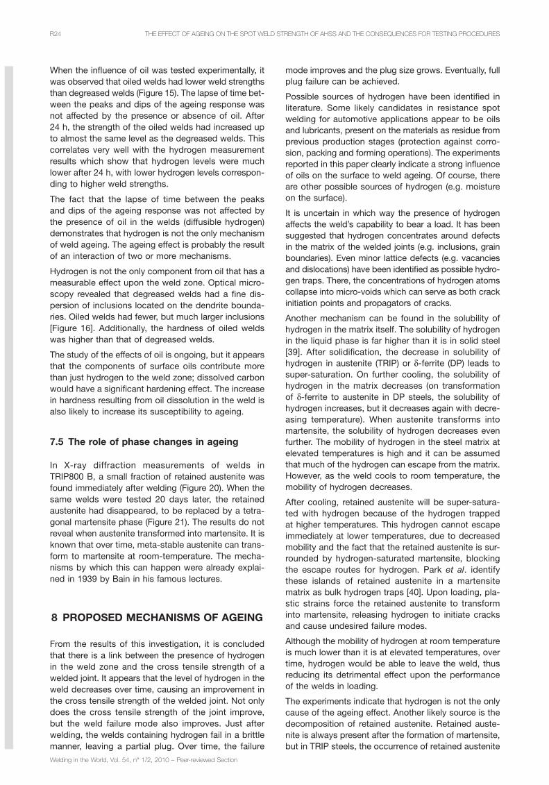
When the infl uence of oil was tested experimentally, it was observed that oiled welds had lower weld strengths than degreased welds (Figure 15). The lapse of time bet-ween the peaks and dips of the ageing response was not affected by the presence or absence of oil. After 24 h, the strength of the oiled welds had increased up to almost the same level as the degreased welds. This correlates very well with the hydrogen measurement results which show that hydrogen levels were much lower after 24 h, with lower hydrogen levels correspon-ding to higher weld strengths.
The fact that the lapse of time between the peaks and dips of the ageing response was not affected by the presence of oil in the welds (diffusible hydrogen) demonstrates that hydrogen is not the only mechanism of weld ageing. The ageing effect is probably the result of an interaction of two or more mechanisms.
Hydrogen is not the only component from oil that has a measurable effect upon the weld zone. Optical micro-scopy revealed that degreased welds had a fi ne dis-persion of inclusions located on the dendrite bounda-ries. Oiled welds had fewer, but much larger inclusions [Figure 16]. Additionally, the hardness of oiled welds was higher than that of degreased welds.
The study of the effects of oil is ongoing, but it appears that the components of surface oils contribute more than just hydrogen to the weld zone; dissolved carbon would have a signifi cant hardening effect. The increase in hardness resulting from oil dissolution in the weld is also likely to increase its susceptibility to ageing.
7.5 The role of phase changes in ageing
In X-ray diffraction measurements of welds in TRIP800 B, a small fraction of retained austenite was found immediately after welding (Figure 20). When the same welds were tested 20 days later, the retained austenite had disappeared, to be replaced by a tetra-gonal martensite phase (Figure 21). The results do not reveal when austenite transformed into martensite. It is known that over time, meta-stable austenite can trans-form to martensite at room-temperature. The mecha-nisms by which this can happen were already explai-ned in 1939 by Bain in his famous lectures.
8 PROPOSED MECHANISMS OF AGEING
From the results of this investigation, it is concluded that there is a link between the presence of hydrogen in the weld zone and the cross tensile strength of a welded joint. It appears that the level of hydrogen in the weld decreases over time, causing an improvement in the cross tensile strength of the welded joint. Not only does the cross tensile strength of the joint improve, but the weld failure mode also improves. Just after welding, the welds containing hydrogen fail in a brittle manner, leaving a partial plug. Over time, the failure

THE EFFECT OF AGEING ON THE SPOT WELD STRENGTH OF AHSS AND THE CONSEQUENCES FOR TESTING PROCEDURES R25
Welding in the World, Vol. 54, n° 1/2, 2010 – Peer-reviewed Section
ding. In general, weld ageing leads to an improvement in mechanical properties, a factor that should be taken into account in standardized weld testing.
Although much is still unknown about the mechanisms of ageing and what really happens within the weld microstructure after welding, this investigation was able to reveal certain important characteristics of the ageing effect:– Ageing is an effect that increases grain boundary fracture toughness in the weld zone.– The ageing response leads to an initial peak in weld strength, followed by a dip and a fi nal strength increase at around 24 h after welding.– A measurable ageing effect occurs in certain highly-alloyed steels that combine a high weld zone hardness and low phosphor content.– Oil on the sheet surface acts to increase the level of the weld ageing response.– Oil has a negative infl uence on weld properties.– Hydrogen from surface oil contributes to weld ageing.– Other components of oils also affect the weld microstructure by increasing the weld hardness and infl uencing the size and distribution of inclusions.– Based upon the results of this investigation, a hypo-thesis has been proposed to explain the ageing phe-nomenon.
ACKNOWLEDGEMENTS
The authors would like to thank David Hanlon, Steven Celotto and Murugaiyan Almithalingam for their advice. Tom Moolevliet, Gabe van de Zwaag and Stefan Melt-zer for their experimental contributions and technical assistance.
REFERENCES
[1] Vasilash G.S.: Better car building through steel – But not the material you’re familiar with – On Materials, Auto-motive Design & Production, March, 2002.
[2] Vasilash G.S.: Better vehicles through steel: advances are being made in steel that can lead to better, safer, more fuel-effi cient vehicles without taking a huge economic hit – Materials, Automotive Design & Production, April 2003.
[3] den Uijl N.J.: Post weld heat treatment of Advanced High Strength Steel for automotive joining, 8th Internatio-nal Seminar “Numerical Analysis of Weldability”, Seggau, 2006.
[4] Chao Y.J.: Failure mode of spot welds: interfacial vs pullout, Science and Technology of Welding and Joining, 2003, vol. 8, no. 2, pp. 133-137.
[5] den Uijl N.J., Smith S.: Resistance spot welding of Advanced High Strength Steels for the automotive indu-stry, 4th International Seminar on Advances in Resistance Welding, Wels, Austria, 2006.
[6] G. Shi, Westgate S.A.: Resistance spot welding of high strength steels, JOM – Eleventh International Conference on the Joining of Materials, May 25-28, 2003, Helsingor, Denmark.
after welding (and the amount of austenite present) is even more likely due to their chemical composition. The retained austenite forms pockets of decreased mecha-nical performance in the martensitic welds, leading to low weld strengths and undesirable failure modes.
The retained austenite is not stable. There is diffusion of elements, changing local chemical composition and there is relaxation of local stress levels which allows for the decomposition of austenite into bcc iron phases. Over time, the weld will thus gain in strength and lose certain possible paths for crack propagation.
9 THE IMPLICATIONS OF WELD AGEINGFOR STANDARDIZED TESTING
Under normal practices, welds are tested mechanically soon after welding, whereas in reality, no automobile is placed on the open market until more than 24 h after welding.
Although not all AHSS materials exhibit the phenomena of weld ageing, the effect can be seen in a signifi cant portion of AHSS grades.
When weld ageing does occur, the weld mechanical properties vary signifi cantly over the fi rst 24 h after the weld was made. This time-related behaviour has very serious implications for standardized testing procedu-res. A weld tested immediately after welding may pro-duce low weld strengths and poor failure modes, lea-ding to the conclusion that the material does not have an adequate weld performance. Whereas the same welds tested 24 h later would have been accepted.
The problem is that most welding standards do not specify a timescale between welding and mechanical testing. Many standards do not specify if a material should be welded in as-received (oiled) condition or degreased, but oil has a very signifi cant effect on weld performance in ageing sensitive materials.
The weld schedule used is also of great importance. If very long hold times are applied, then ageing can be induced in materials where no ageing effect would normally be found (such as DP600). If the weld sche-dule used for material acceptance is not the same as the one applied in production, then further disparities could occur between measured results.
10 CONCLUSIONS
The experiments carried out demonstrate that the ageing effect is a very real phenomenon. However, ageing does not occur in most low carbon steels under normal welding conditions. With increasing levels of alloying additions, steels can become more sensitive to ageing and less rapid cooling rates are required to activate the effect.
In ageing sensitive materials, the spot weld mechanical properties can fl uctuate signifi cantly within 24 h of wel-

THE EFFECT OF AGEING ON THE SPOT WELD STRENGTH OF AHSS AND THE CONSEQUENCES FOR TESTING PROCEDURESR26
Welding in the World, Vol. 54, n° 1/2, 2010 – Peer-reviewed Section
[23] Gould J.E., Khurana S.E., Li T.: Predictions of microstructures when welding automotive advanced high-strength steels, Welding Journal Research Supplement, 2006, vol. 85, no. 5, pp. 111s-116s.
[24 Gould J.E.: Weld process effects cracking – Hold time sensitivity and RSW of high strength steel, Welding Design and Fabrication, 1999, vol. 8, pp. 48-49.
[25] Westgate S.: The resistance spot welding of high and ultra-high strength steels, Proceedings of the 3rd Interna-tional Seminar on Advances in Resistance Welding, Berlin, 2004.
[26] Mimer M., Svensson L-E., Johansson R.: Possibilities to improve fracture behaviour in resistance spot welds of EHSS and UHSS by process modifi cations, Proceedings of the 3rd International Seminar on Advances in Resi-stance Welding, Berlin, 2004.
[27] Radaj D.: Heat effects of welding – Temperature fi eld, residual stress, distortion, ISBN 0-387-54820-3, Springer-Verlag, 1992.
[28] Mantell C.L. (ed.): Engineering Materials Handbook 1st ed., Mc Graw-Hill, 1958.
[29] Chandler H.: Metallurgy for the Nion-Metallurgist, ASM International, ISBN 0-87170-652-0, 1998.
[30] Sawhill J.M. Jr., Baker J.C.: Spot weldability of high strength sheet steels, AWS annual meeting, Detroit, 1979.
[31] Mohrbacher H.: Welding of automotive high strength steel from a Nb microalloying point of view, Automotive Circle International – Conference, Bad Nauheim/Frankfurt, Germany, 2006.
[32] Mohrbacher H.: Joining state-of-the-art high strength steels – Infl uences and optimisation from a metallurgical poit of view, Automotive Circle International – Conference, Bad Nauheim/Frankfurt, Germany, 2007.
[33] Bain E.C.: Functions of the alloying elements in steel, A series of fi ve educational lectures on the functions of the alloying elements in steel presented to members of the A.S.M. during the twenty fi rst national metal congress and exposition, Chicago, Illinois, October 23 to 27, 1939.
[34] Pickering F.B.: Physical metallurgy of stainless steel developments, International Metallurgical Reviews, 1976, vol. 21, pp. 227-268.
[35] Neely J.: Practical Metallurgy and Materials of Indu-stry, John Wiley and Sons, 1979.
[36] Bhadeshia H.K.D.H.: Tempered Martensite, www.msm.cam.ac.uk/phase-trans/2004/Tempered.Martensite/tempered.martensite.html, accessed June 8, 2008.
[37] ISO 14329:2003: Resistance welding – Destructive tests of welds – Failure types and geometric measure-ments for resistance spot, seam and projection welds.
[38] ISO 14272:2000: Specimen dimensions and pro-cedure for cross tension testing resistance spot and embossed projection welds.
[39] Failure analysis and prevention, volume 8, Metal handbook volume 10, H.E. Boyer (ed.), ASM Handbook committee, 1975.
[40] Park Y.D., Maroef I.S., Landau A., Olson L.: Retained austenite as a hydrogen trap in steel welds, Welding Jour-nal Research Supplement, February, 2002, vol. 81, no. 2, pp. 27-s-35-s.
[7] Shi G., Westgate S.A.: TRIP steel – Better weldability using resistance spot welding, TWI bulletin, 2007.
[8] Marya M., Gayden X.Q.: Development of requirements for resistance spot welding Dual-Phase (DP600) Steels Part 1: The causes of interfacial fracture, Welding Journal, November 2005, vol. 84, no. 11, pp. 172-s-182-s.
[9] Marya M., Gayden X.Q.: Development of requirements for resistance spot welding Dual-Phase (DP600) Steels Part 2: Statistical Analyses and Process Maps, Welding Jour-nal, December 2005, vol. 84, no. 12, pp. 197-s-204-s.
[10] Verstraeten B., Feyaerts J.: Weerstandslassen van hogesterkte staalsoorten, Resistance welding of high-strength steels, Lastechniek, December 2006 (in Dutch).
[11] Easterling K.: Introduction to the physical metallurgy of welding 2nd ed., Butterworth Heinemann, ISBN 0 7506 0394 1, 1992.
[12] den Uijl N.J.: Modelling the infl uence of resistance spot welding on material properties, 3rd International Con-ference on Mathematical Modelling and Information Tech-nologies in Welding and Related Processes, Kiev, 2006.
[13] N.J. den Uijl, H. Nishibata, S. Smith, T. Okada, T. van der Veldt, M. Uchihara, K. Fukui: Prediction of post weld hardness of advanced high strength steels for automotive application using a dedicated carbon equivalent number, IIW Doc. III-1444-07, Presented at the Annual Assembly 2007, Commission III Resistance welding, solid state welding and allied joining processes, Dubrovnik, Croatia, 2-4 July, 2007.
[14] IIW Technical Report, IIW doc. IX-535-67, June 5, 1967.
[15] Ito Y., Bessyo K.: Weldability formula of high strength steel related to heat affected zone cracking, Journal of Japanese Welding Society, 1968, vol. 37, no. 9, pp. 938
[16] Blondeau R., Maynier Ph., Dollet J.: Prévision de la dureté et de la résistance des aciers au carbone et faiblement alliés d‘après leur structure et leur composition, Prediction of hard-ness and resistance of carbon an low alloy steels depending on their structure and composition, Mémoires Scientifi ques Revue Métallurgie, 1973, LXX, no. 12 (in French).
[17] Blondeau R., Maynier Ph., Dollet J., Vieillard-Baron B.: Prévision de la dureté et de la résistance des aciers au carbone et faiblement alliés d‘après leur composition et leur traitement thermique, Prediction of hardness and resistance of carbon an low alloy steels depending on their structure and heat treatment, Mémoires Scientifi ques Revue Métallurgie, Novembre 1975 (in French).
[18] Chaillet J.M., Chevet F., Bocquet P., Dollet J.: Pre-diction of the microstructure and tensile properties of weld metal deposits, Welding of HSLA (microalloyed) structural steels, Proceedings of an International Conference, 9-12 November 1976, Rome, Italy, pp. 298-321.
[19] Porter D.A., Easterling K.E.: Phase transformations in metals and alloys, Van Nostrand Reinhold, 1981.
[20] Andrews K.W.: Empirical formulae for the calculation of some transformation temperatures, Journal of the Iron and Steel Institute, 1965, vol. 203, Part 7.
[21] Koistinen D.P., Marburger R.E.: A general equation prescribing the extent of the austenite-martensite transfor-mation in pure iron-carbon alloys and plain carbon steels, Acta Metallurgica, 1959, vol. 7, no. 5, pp. 59–60.
[22] Steven W., Haynes A.G.: The temperature of forma-tion of martensite and bainite in low alloy steels, Journal of the Iron and Steel Institute, 1956, vol. 183, pp. 349-359.