Embed Size (px)
Citation preview

The Effect of a Metal Plate Barrier with Circular Holes in theForced Convection of Electronic Equipment
Masao FujiiDepartment of Intelligent Systems, Kinki University, Japan
Two rectangular block-like elements configured as an electronic module arepositioned in a parallel-walled channel and cooled by forced convection airflow. Ametal plate with circular holes as a barrier protrudes above the plane of the modules,which is intended to function as a cover for protecting them from mechanical orelectromagnetic damage, or as a thermal control device. The per-module heat transfercoefficients were measured in the presence of the barrier with various heights, H, anddistances, L, between the module and the barrier. In the presence of the barrier withcircular holes, the heat transfer coefficient for the two modules was significantlyreduced. The corresponding Nusselt numbers are determined as a function of theReynolds number and the H/L ratio. © 2009 Wiley Periodicals, Inc. Heat Trans AsianRes, 39(2): 116–126, 2010; Published online 14 December 2009 in Wiley InterScience(www.interscience.wiley.com). DOI 10.1002/htj.20279
Key words: electronic cooling, forced convection, barrier, hole, heat transfer,thermal control
1. Introduction
Electronic devices produce heat as a by-product of normal operation. When electrical currentflows through a semiconductor or a passive device, a portion of the power is dissipated as heat energy.When a device exceeds its specified temperature, its performance, life, and reliability are greatlyreduced. Therefore, the projected heat transfer of electronic components is of prime importance inthe design of digital electronic equipment with high densities of dissipated electrical power.
Owing to flow passage diversities and irregularities, there has been less fundamental researchon electronic equipment cooling than on other topics of heat transfer. Sparrow et al. [1–3] reportedthe most common generic configuration for electronic cooling, in which an array of rectangularheat-generating modules deployed along one wall of a flat rectangular duct is cooled by forcedconvection airflow. In these reports, a barrier set in the flat rectangular duct, acting as a turbulencepromoter, was shown to enhance the heat transfer coefficient of the module.
The work reported here focuses on the effect of a barrier on the heat transfer of a module thathas particularly high heat dissipation and/or crucial temperature limitation, such as a central process-ing unit. The electronic equipment is usually covered with a metal or perforated metal plate to protect
© 2009 Wiley Periodicals, Inc.
Heat Transfer—Asian Research, 39 (2), 2010
116

it from mechanical or electromagnetic damage. The metal plate works as the barrier or as a thermalcontrol device. Compared with the barrier described by Sparrow et al. [1–3], the barrier reported hereis higher and the spacing between the barrier and the modules longer, so the barrier does not alwaysenhance the heat transfer. Furthermore, in electronic equipment, various electronic components on acircuit board act as barriers that reduce each other’s heat transfer capabilities.
Regarding the effect of a barrier on forced convection heat transfer, Shiina et al. [4] studiedthe effect of thin plate obstacles parallel to the duct, and Tanazawa et al. [5] reported that a perforatedplate promotes turbulence. Fujii and Seshimo [6, 7] presented the effect of perforations of a heatexchanger with passage enlargement and contraction. These reports were related to heat transfer ona plain smooth heating surface.
In practice, however, it is important to study the effect of the barrier on the forced convectionheat transfer of the module covered surface for the cooling of electronic equipment.
I previously reported the effect of the metal plate barrier without holes on the heat transfer ofthe module covered surface [8], in which the heat transfer was enhanced at the 2nd row module, butdiminished at the 1st row module.
In this report, a metal plate with circular holes was used as the barrier to study the effect ofthe air flow through the holes on the heat transfer of the module covered surface.
Nomenclature
A: per-module heat transfer area except bottom surface area of the module, m2
D: characteristic length, m
G: gap between the top edge of the barrier and the top plate of the duct in Fig. 1, mm
H: height of the barrier in Figs. 1 and 2, mm
h: heat transfer coefficient, W/(m2K)
K: pressure loss coefficient
k: thermal conductivity of air, W/(m⋅K)
L: spacing between the front edge of each module and the barrier, mmNu: Nusselt number
Pr: Prandtl number of air
Q: heat flow rate, W
Re: Reynolds number
Tw: temperature of module, K
Ta: inlet air temperature, K
v: mean air velocity, m/s
Greek Symbols
∆P: pressure loss, Pa
n: kinematic viscosity of air, m2/s
ρ: density of air, kg/m3
117

Subscripts
i: module number(i = 1: 1st module, i = 2: 2nd module)
b: barrier
2. Experimental Apparatus and Procedure
Two rectangular heat-generating block-like elements representing electronic modules weredeployed along one wall of a flat rectangular duct and cooled by forced convection airflow as shownin Fig. 1.
The rectangular duct was 600 mm long, 100 mm wide, and 85 mm high, and made of acrylicresin. Each module was a square aluminum block, for which the dimensions were fixed with a sidelength of 30 mm, and a thickness of 15 mm. There was a 2.0 mm thick acrylic resin plate on the baseof each module, and the modules were attached to the bottom plate of the rectangular duct with 1.0mm thick adhesive tape.
The modules were heated simultaneously with a rubber heater implanted in each module. Theheat flow rate of each module was 3.5 to 8.0 W within an uncertainty of ±0.45%. The temperature ofeach module, Twi, was measured with a 0.2-mm outer diameter copper constantan thermocouple, andfound to be 338 to 358 K. The inlet temperature of air, Ta, entering the duct was about 301 K. Thetemperature difference (Twi – Ta) was within an uncertainty of ±0.21%. A 13-mm thick air gap was
Fig. 1. Experimental apparatus.
118

set under the bottom plate of the duct to insulate the heat flow (heat loss) from the modules.Thermocouples were set on the bottom plate of the duct on the air gap side, corresponding to eachmodule, and measurements, Tsi, were taken. Heat loss from each module to the air gap was estimatedby the temperature difference (Twi – Tsi) as shown in Ref. 8. The mean air velocity v in the duct withoutmodules was 0.54 to 2.7 m/s within an uncertainty of ±1%, and was used as the characteristic velocityfor the Reynolds number defined in Section 3. As the Reynolds number increased, the heat lossdecreased. The heat loss was used to obtain the heat flow rate Qi dissipated from each module to theair flow in the duct.
A metal plate made of aluminum 0.5 mm thick with circular holes as a barrier protruded abovethe plane of the modules. The holes of the metal plate were distributed at the apex of an equilateral
Fig. 2. Barrier with circular holes.
Table 1. Setting Dimensions of the Barrier
119

triangle in a staggered array, with a diameter of 3 mm and with a constant pitch corresponding to aporosity of 32.6%, as shown in Fig. 2.
Table 1 gives the setting dimensions of the barrier on the bottom plate of the duct. Geometricalparameters that varied during the experiments were the height H of the barrier and the spacing Lbetween the module and the barrier. The height H was set at 27, 36, or 54 mm (i.e., 1.5, 2.0, or 3.0times the height of the module, respectively). Two spacings, L1 and L2, were used in this study. Thespacing between the front edge of the 1st module and the barrier L1 was set at 10, 20, 30, 50, or 100mm and the spacing between the front edge of the 2nd module and the barrier was set at L2 = L1 + 60mm.
The pressure drop ∆P was measured with a pressure gauge with a resolution of ±0.1 Pa, andobtained by measuring the difference between the wall static pressure 270 mm ahead of the front edgeof the 1st module and the atmospheric pressure in the laboratory.
3. Results and Discussion of Heat Transfer
The heat transfer coefficient is obtained as
hi = Qi/{A(Twi – Ta)} (1)
The heat transfer and pressure drop characteristics are presented in terms of dimensionlessgroups:
Nui = hiD/k
Re = vD/n
The characteristic length D = 30 mm was the side length of the module. The average of theinlet air temperature Ta and the heating surface temperature of the module Twi was used in the datareduction.
3.1 No barrier [8]
The dimensionless correlations for the 1st and 2nd modules were obtained within an uncer-tainty of ±3%:
Nu1 = 0.168Re0.719Pr1/3 for the 1st module (2)
Nu2 = 0.284Re0.637Pr1/3 for the 2nd module (3)
where 940 ≤ Re ≤ 4400.
3.2 Barrier without holes [8]
Figure 3 shows the dimensionless correlation of experimental results for the barrier withoutholes.
120
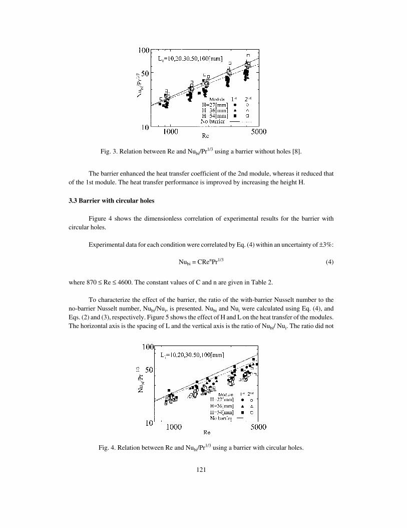
The barrier enhanced the heat transfer coefficient of the 2nd module, whereas it reduced thatof the 1st module. The heat transfer performance is improved by increasing the height H.
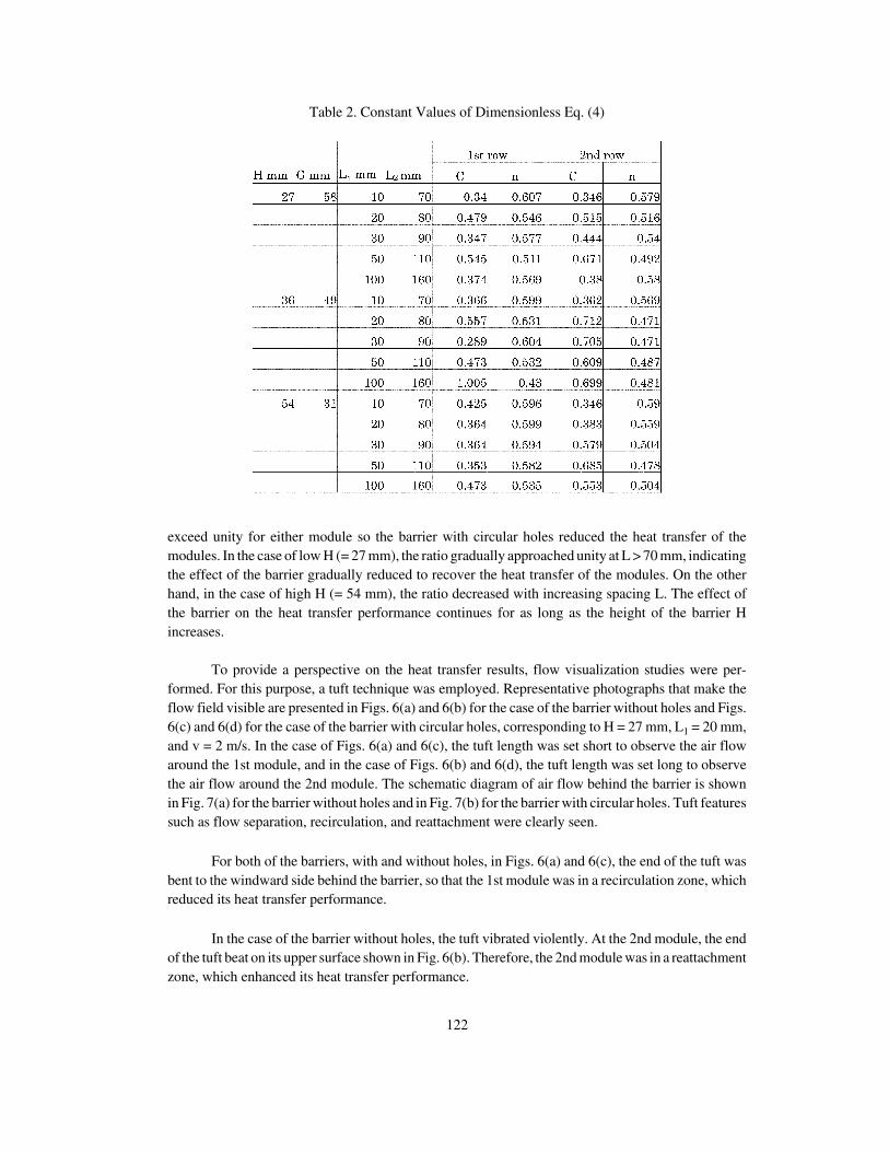
3.3 Barrier with circular holes
Figure 4 shows the dimensionless correlation of experimental results for the barrier withcircular holes.
Experimental data for each condition were correlated by Eq. (4) within an uncertainty of ±3%:
Nubi = CRenPr1/3 (4)
where 870 ≤ Re ≤ 4600. The constant values of C and n are given in Table 2.
To characterize the effect of the barrier, the ratio of the with-barrier Nusselt number to theno-barrier Nusselt number, Nubi/Nui, is presented. Nubi and Nui were calculated using Eq. (4), andEqs. (2) and (3), respectively. Figure 5 shows the effect of H and L on the heat transfer of the modules.The horizontal axis is the spacing of L and the vertical axis is the ratio of Nubi/ Nui. The ratio did not
Fig. 3. Relation between Re and Nubi/Pr1/3 using a barrier without holes [8].
Fig. 4. Relation between Re and Nubi/Pr1/3 using a barrier with circular holes.
121
exceed unity for either module so the barrier with circular holes reduced the heat transfer of themodules. In the case of low H (= 27 mm), the ratio gradually approached unity at L > 70 mm, indicatingthe effect of the barrier gradually reduced to recover the heat transfer of the modules. On the otherhand, in the case of high H (= 54 mm), the ratio decreased with increasing spacing L. The effect ofthe barrier on the heat transfer performance continues for as long as the height of the barrier Hincreases.
To provide a perspective on the heat transfer results, flow visualization studies were per-formed. For this purpose, a tuft technique was employed. Representative photographs that make theflow field visible are presented in Figs. 6(a) and 6(b) for the case of the barrier without holes and Figs.6(c) and 6(d) for the case of the barrier with circular holes, corresponding to H = 27 mm, L1 = 20 mm,and v = 2 m/s. In the case of Figs. 6(a) and 6(c), the tuft length was set short to observe the air flowaround the 1st module, and in the case of Figs. 6(b) and 6(d), the tuft length was set long to observethe air flow around the 2nd module. The schematic diagram of air flow behind the barrier is shownin Fig. 7(a) for the barrier without holes and in Fig. 7(b) for the barrier with circular holes. Tuft featuressuch as flow separation, recirculation, and reattachment were clearly seen.
For both of the barriers, with and without holes, in Figs. 6(a) and 6(c), the end of the tuft wasbent to the windward side behind the barrier, so that the 1st module was in a recirculation zone, whichreduced its heat transfer performance.
In the case of the barrier without holes, the tuft vibrated violently. At the 2nd module, the endof the tuft beat on its upper surface shown in Fig. 6(b). Therefore, the 2nd module was in a reattachmentzone, which enhanced its heat transfer performance.
Table 2. Constant Values of Dimensionless Eq. (4)
122

Fig. 6. Flow visualization.
Fig. 5. Effect of height H and length L.
123

However, in the case of the barrier with circular holes, the tuft did not vibrate violently, butgently, similar to the case with no barrier [8]. As shown in Fig. 7(b), the air passing through the holesof the barrier appear to lift the stagnation zone behind the barrier, enlarging the recirculation zonecompared with the case of the barrier without holes, and precludes the reattachment of the flow to the2nd module. This tendency increases for the barrier with greater height.
3.4 Dimensionless correlation of the heat transfer in the presence of the barrier with circularholes
The air flow through the gap G and holes of the barrier has a very complicated influence onthe heat transfer performance of the modules.
Figure 8 shows the dimensionless correlation of the heat transfer coefficient of the modules.The horizontal axis is a dimensionless number H/L and the vertical axis is defined by
Zi = Nubi/(Re0.54Pr1/3)
The experimental data were correlated within an uncertainty of ±11% as
0.17 ≤ H/L < 0.43
Nubi = 0.37Re0.54Pr1/3(H/L)–0.15 (5)
0.43 ≤ H/L ≤ 5.4
Nubi = 0.48Re0.54Pr1/3(H/L)0.17 (6)
where 870 ≤ Re ≤ 4600. At H/L = 0.43, the influence of H/L on the heat transfer performance changed.
Fig. 7. Schematic diagram of air flow behind the barrier.
124

An attempt was made to correlate the experimental results using the dimensionless numberG/L, without success, whereas in the case of the barrier without holes, the experimental results werewell correlated using G/L [8]. In the case of the barrier with circular holes, the heat transferperformance of the module is strongly influenced by the air flow thorough the holes of the barrier.
4. Results and Discussion on Pressure Loss
Figure 9 shows the pressure loss coefficient K defined by Eq. (7):
K = 2∆P/(ρv2) (7)
The net incremental pressure loss ∆P associated with the presence of the barrier is of practicalinterest. The pressure loss of the barrier was obtained by subtracting the pressure loss of the modulesfrom the total experimental pressure loss of the modules and the barrier [8]. The data in Fig. 9 includesthe effect of the spacing L and Reynolds number. The pressure loss coefficient increased withincreasing H, whereas it was quite insensitive to both L and Reynolds number in the rangeinvestigated.
Fig. 9. Pressure loss coefficient.
Fig. 8. Dimensionless correlation.
125

5. Conclusions
The heat transfer performance of each module using the barrier with circular holes was studiedexperimentally to obtain the following conclusions.
(1) The heat transfer performance of both modules is reduced by the barrier with circular holes.This tendency increased with increasing Reynolds number.
(2) The heat transfer performance of the module is strongly influenced by the air flow throughthe holes of the barrier. It decreases with an increase in spacing L, and this tendency is particularlyevident for the higher barrier.
(3) The heat transfer performance of each module changes at H/L = 0.43, and is well correlatedby Eqs. (5) and (6).
(4) The pressure loss coefficient of the barrier with circular holes is influenced by the heightof the barrier H, and is insensitive to the spacing L and Reynolds number.
Literature Cited
1. Sparrow EM, Niethammer JE, Chaboki A. Heat transfer and pressure drop characteristics ofarrays of rectangular modules encountered in electronic equipment. Int J Heat Mass Trans1982;25:961–973.
2. Sparrow EM, Vemuri SB, Kadle DS. Enhanced and local heat transfer, pressure drop, and flowvisualization for arrays of block-like electronic components. Int J Heat Mass Trans1983;26:689–699.
3. Sparrow EM, Otis DR Jr. Ductflow heat transfer at a smooth wall which faces a wall coveredby protuberances. Int J Heat Mass Trans 1985;28:1317–1326.
4. Shiina K, Nakamura S, Shimizu N. Enhancement of forced convective heat transfer in arectangular channel using thin plate-type obstacles. Trans Japan Soc Mech Eng 1988;54:148–154. (in Japanese)
5. Tanazawa I, Nishio S, Takano K, Tado M. Enhancement of forced convection heat transfer inrectangular duct by turbulence promoter. Trans Jpn Soc Mech Eng 1983;49:676–684. (inJapanese)
6. Fujii M, Seshimo Y. Heat transfer and pressure drop of perforated heat exchanger with passageenlargement and contraction. Int J Heat Mass Trans 1988;31:135–142.
7. Fujii M, Seshimo Y. Enhanced heat transfer method “Breathing effect” at low Reynoldsnumber and its applications. Trans JSRAE 2002;19:329–338. (in Japanese)
8. Fujii M. Effect of metal plate barrier without holes in forced convection of electronicequipment. Trans JSME 2008;74:901–906. (in Japanese)
"F F F"
Originally published in Trans JSME Ser B 75, 2009, 107–112.Translated by Masao Fujii, Department of Intelligent Systems, Kinki University, 930 Nishimitani,
Kinokawa city, Wakayama 649-6493, Japan.
126