Embed Size (px)
Citation preview
THE DP-GMAW TECHNIQUE ON ALUMINUM BUILD-UP PROCESS FOR ADDITIVE MANUFACTURING
(THESIS PROPOSAL)
JUKKAPUN GREEBMALAI
A THESIS SUBMITTED IN PARTIAL FULFILLMENT OF THE REQUIREMENTS FOR THE DEGREE OF
MASTER OF ENGINEERING (INDUSTRIAL ENGINEERING) FACULTY OF GRADUATE STUDIES
MAHIDOL UNIVERSITY 2019
COPYRIGHT OF MAHIDOL UNIVERSITY
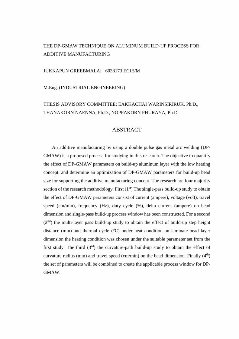
THE DP-GMAW TECHNIQUE ON ALUMINUM BUILD-UP PROCESS FOR
ADDITIVE MANUFACTURING
JUKKAPUN GREEBMALAI 6038173 EGIE/M
M.Eng. (INDUSTRIAL ENGINEERING)
THESIS ADVISORY COMMITTEE: EAKKACHAI WARINSIRIRUK, Ph.D.,
THANAKORN NAENNA, Ph.D., NOPPAKORN PHURAYA, Ph.D.
ABSTRACT
An additive manufacturing by using a double pulse gas metal arc welding (DP-
GMAW) is a proposed process for studying in this research. The objective to quantify
the effect of DP-GMAW parameters on build-up aluminum layer with the low heating
concept, and determine an optimization of DP-GMAW parameters for build-up bead
size for supporting the additive manufacturing concept. The research are four majority
section of the research methodology. First (1st) The single-pass build-up study to obtain
the effect of DP-GMAW parameters consist of current (ampere), voltage (volt), travel
speed (cm/min), frequency (Hz), duty cycle (%), delta current (ampere) on bead
dimension and single-pass build-up process window has been constructed. For a second
(2nd) the multi-layer pass build-up study to obtain the effect of build-up step height
distance (mm) and thermal cycle (°C) under heat condition on laminate bead layer
dimension the heating condition was chosen under the suitable parameter set from the
first study. The third (3rd) the curvature-path build-up study to obtain the effect of
curvature radius (mm) and travel speed (cm/min) on the bead dimension. Finally (4th)
the set of parameters will be combined to create the applicable process window for DP-
GMAW.

iii
CONTENTS Page
ABSTRACT ................................................................................................................... ii CONTENTS ................................................................................................................. iii LIST OF FIGURES ...................................................................................................... iv
LIST OF TABLES ......................................................................................................... v
INTRODUCTION ................................................................................ 1
1.1 Research Background .......................................................................................... 1
1.2 Research Objective .............................................................................................. 4
1.3 Scope of Work ..................................................................................................... 5
1.4 Expected Result ................................................................................................... 6
LITERATURE REVIEW ..................................................................... 7
2.1 Double Pulse Gas Metal Arc Welding ................................................................. 7
2.2 Wire-Feed Additive Manufacturing ................................................................... 10
2.3 Gas Metal Arc Welding in Additive Manufacturing ......................................... 12
2.3 Adaptive Control in Additive Manufacturing .................................................... 16
RESEARCH METHODOLOGY ....................................................... 20
3.1 Research Methodology ...................................................................................... 20
3.2 Materials and Equipment ................................................................................... 21
Material ................................................................................................................ 21
Welding Machine ................................................................................................. 22
Welding Robot ..................................................................................................... 23
Signal Collecting System ..................................................................................... 23
3.3 Experimental Design and Setup ......................................................................... 24
Experimental Design ............................................................................................ 24
Experimental Setup .............................................................................................. 26
3.4 Research Framework and Time Schedule.......................................................... 28
REFERENCES ............................................................................................................ 29
iv
LIST OF FIGURES Page
Figure 1.1 Process for Produce and Repair Aluminum Part .......................................... 1 Figure 1.2 Qualitative of the AM Metal Components Production Relative to Usual Options [4] ................................................................................................... 2 Figure 1.3 Investment Cost ............................................................................................ 3 Figure 1.4 Current Characteristic and Weld Bead Result [1] ........................................ 4 Figure 2.1 Gas Metal Arc Welding ................................................................................ 7 Figure 2.2 Double Pulse Current ................................................................................... 8 Figure 2.3 Current Characteristic in Each Period Current [1] ....................................... 8 Figure 2.4 Arc Characteristic during Background Pulse Current [1] ............................ 8 Figure 2.5 DP-GMAW Welding Variables [1] .............................................................. 9 Figure 2.6 Cross-Section of the Single Deposit with Different Set of Laser Power ... 10 Figure 2.7 Schematic of the building direction and deposition direction of the wall structure, and the cross-section [4] .............................................................................. 11 Figure 2.8 The Principle of Layer Thickness Adjustment ........................................... 11 Figure 2.9 Approximate Surface .................................................................................. 12 Figure 2.10 Schematic Diagram of GMAW-Base AM Process [6] ............................. 13 Figure 2.11 Process parameter area of various from the appearance in single-layer bead [6] .................................................................................................... 13 Figure 2.12 Various forming appearance with a different combination of process parameters ................................................................................................ 14 Figure 2.13 Maximum Heat Input for Acquiring a Good Formation with the Difference Current [6] ............................................................................. 15 Figure 2.14 Schematic Diagram of GMAW-Base LAM System [7] ........................... 16 Figure 2.15 Schematic of Vision Sensor System [7] ................................................... 17 Figure 2.16 Schematic Diagram of Adaptive Controller for NTSD [7] ...................... 17 Figure 2.17 NTSD Measurements of Various Layer for 21 Layer Wall ..................... 18 Figure 2.18 Adaptive Control Result of Difference Layer .......................................... 19 Figure 3.1 Research Methodology ............................................................................... 20 Figure 3.2 Welding Machine ....................................................................................... 22 Figure 3.3 Welding Robot............................................................................................ 23 Figure 3.4 Connecting sensor to measure welding signal ............................................ 23 Figure 3.5 Schematic of Experimental Setup .............................................................. 27 Figure 3.6 Experimental Setup .................................................................................... 27

v
LIST OF TABLES Page
Table 1.1 The Research Expected Output...................................................................... 6 Table 1.2 The Research Expected Outcome .................................................................. 6 Table 3.1 Chemical Composition of for Build-up Layer [8, 9] ................................... 22 Table 3.2 Single-Pass Build-Up Experimental Design ................................................ 24 Table 3.3 Multi-Layer Build-Up Experimental Design ............................................... 25 Table 3.4 Curvature-Path Build-Up Experimental Design .......................................... 26 Table 3.5 Equipment list for Welding Signal Collecting System ................................ 28 Table 3.6 Research Framework and Time Schedule ................................................... 28


Fac. of Grad. Studies, Mahidol Univ. M.Eng. (Industrial Engineering) / 1
INTRODUCTION
1.1 Research Background
The aluminum alloy widely used in many application such as automotive, aircraft, marine, corrosion resistance tank or vessel and much more application. To produce a complicated-shape aluminum part as used in aircraft or aerospace. The machining was come to be the first choice for selected to creating. The machining can provide excellent accuracy, but the process needs to cut out the material become scrap, in case of some part had a problematic area to machine the tool cannot reach to that position.
The additive manufacturing (AM) has been developed the build-up process to creating or repairing the metal part to produce the complicated geometry and save the cost of the material and investment. The Additive manufacturing (AM) is the official industry standard term (ASTM F2792) for all applications of the technology. It is defined as the process of joining materials to make objects from 3D model data, usually layer upon layer, as opposed to subtractive manufacturing methodologies. To build-up material layer, the thermal process as welding and laser melting processes has been compatible because the process had been melted the material and continuously formed the layer upon layer. Figure 1.1 shows the comparing between the machining, and AM methodology can be seen that the AM process had the advantage to save more the material cost and less time consumed for repairing the broken part than reconstructing by machining.
Figure 1.1 Process for Produce and Repair Aluminum Part
Jukkapun Greebmalai Introduction / 2
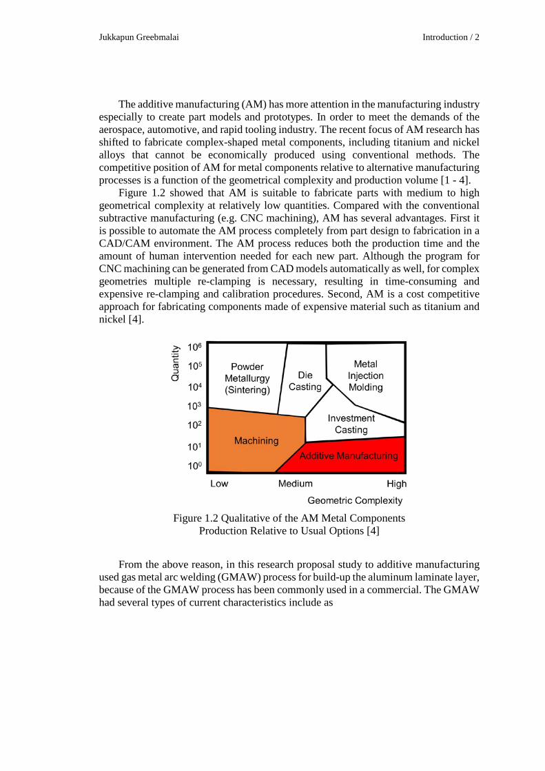
The additive manufacturing (AM) has more attention in the manufacturing industry especially to create part models and prototypes. In order to meet the demands of the aerospace, automotive, and rapid tooling industry. The recent focus of AM research has shifted to fabricate complex-shaped metal components, including titanium and nickel alloys that cannot be economically produced using conventional methods. The competitive position of AM for metal components relative to alternative manufacturing processes is a function of the geometrical complexity and production volume [1 - 4].
Figure 1.2 showed that AM is suitable to fabricate parts with medium to high geometrical complexity at relatively low quantities. Compared with the conventional subtractive manufacturing (e.g. CNC machining), AM has several advantages. First it is possible to automate the AM process completely from part design to fabrication in a CAD/CAM environment. The AM process reduces both the production time and the amount of human intervention needed for each new part. Although the program for CNC machining can be generated from CAD models automatically as well, for complex geometries multiple re-clamping is necessary, resulting in time-consuming and expensive re-clamping and calibration procedures. Second, AM is a cost competitive approach for fabricating components made of expensive material such as titanium and nickel [4].
Figure 1.2 Qualitative of the AM Metal Components
Production Relative to Usual Options [4]
From the above reason, in this research proposal study to additive manufacturing used gas metal arc welding (GMAW) process for build-up the aluminum laminate layer, because of the GMAW process has been commonly used in a commercial. The GMAW had several types of current characteristics include as
Fac. of Grad. Studies, Mahidol Univ. M.Eng. (Industrial Engineering) / 3
1. Cold-metal-transfer current (CMT-current) is current technology to control metal deposition with low heat-input similar to pulse current that occurs short circuit.
2. Double-pulse current (DP-current) is current that combines two conditions of pulse current.
3. Pulse current (P-current) is a short period rise of direct current which changes on an amplitude.
4. Direct current (DC-current) is a common current as supply constant current value.
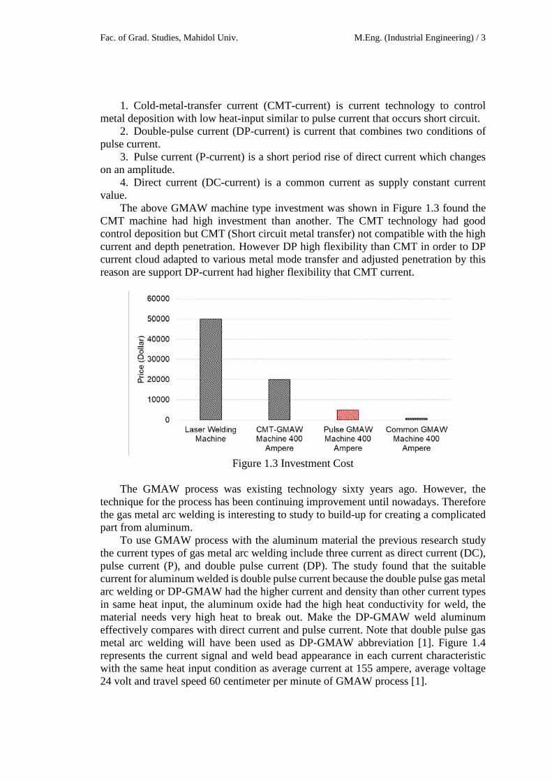
The above GMAW machine type investment was shown in Figure 1.3 found the CMT machine had high investment than another. The CMT technology had good control deposition but CMT (Short circuit metal transfer) not compatible with the high current and depth penetration. However DP high flexibility than CMT in order to DP current cloud adapted to various metal mode transfer and adjusted penetration by this reason are support DP-current had higher flexibility that CMT current.
Figure 1.3 Investment Cost
The GMAW process was existing technology sixty years ago. However, the
technique for the process has been continuing improvement until nowadays. Therefore the gas metal arc welding is interesting to study to build-up for creating a complicated part from aluminum.
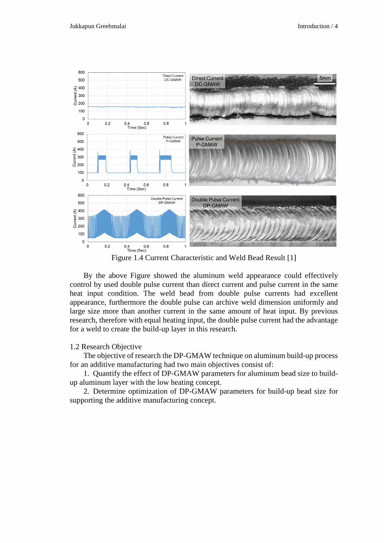
To use GMAW process with the aluminum material the previous research study the current types of gas metal arc welding include three current as direct current (DC), pulse current (P), and double pulse current (DP). The study found that the suitable current for aluminum welded is double pulse current because the double pulse gas metal arc welding or DP-GMAW had the higher current and density than other current types in same heat input, the aluminum oxide had the high heat conductivity for weld, the material needs very high heat to break out. Make the DP-GMAW weld aluminum effectively compares with direct current and pulse current. Note that double pulse gas metal arc welding will have been used as DP-GMAW abbreviation [1]. Figure 1.4 represents the current signal and weld bead appearance in each current characteristic with the same heat input condition as average current at 155 ampere, average voltage 24 volt and travel speed 60 centimeter per minute of GMAW process [1].
Jukkapun Greebmalai Introduction / 4
Figure 1.4 Current Characteristic and Weld Bead Result [1]
By the above Figure showed the aluminum weld appearance could effectively
control by used double pulse current than direct current and pulse current in the same heat input condition. The weld bead from double pulse currents had excellent appearance, furthermore the double pulse can archive weld dimension uniformly and large size more than another current in the same amount of heat input. By previous research, therefore with equal heating input, the double pulse current had the advantage for a weld to create the build-up layer in this research. 1.2 Research Objective
The objective of research the DP-GMAW technique on aluminum build-up process for an additive manufacturing had two main objectives consist of:
1. Quantify the effect of DP-GMAW parameters for aluminum bead size to build-up aluminum layer with the low heating concept.
2. Determine optimization of DP-GMAW parameters for build-up bead size for supporting the additive manufacturing concept.

Fac. of Grad. Studies, Mahidol Univ. M.Eng. (Industrial Engineering) / 5
1.3 Scope of Work The research study in the four main activities includes to parameters for a single
pass, parameters for multi-pass, curvature build-up, and parameters optimization. The result of the previous study will continue used in the next study step by step. The research scope was followed as:
1. The DP-GMAW process studies for the build-up 3D dimension using aluminum filler wire 5356 (ER5356) with a welding robotic.
2. The single pass bead on plate will be studied under the effect of DP-GMAW parameters. Bead height and bead width are measured as a function of the DP parameters.
3. The process of multi-layer build-up will be studies which the topic are consist of:
3.1 The effect of build-up step height distance on the deposited bead shape. The strength build-up line is proposed for this step.
3.2 The thermal cycle under the effect of DP-GMAW for the multi-layer condition was measured by using thermocouples and infrared (IR) camera.
3.3 The effective volumetric build-up will be measured with metallography cross-section. Furthermore the soundness of the multi-layer wall will be measured by the radiographic testing method.
3.4 Process window which consists of DP-GMAW parameters, the boundary of the operation zone will be constructed.
4. The curvature build-up will be studied under the effect of curve radius and travel speed. Bead height and bead width are measured as a function of the curve radius and travel speed.
5. The optimization process parameters are consist of the maximize bead height and minimize bead width on single pass bead. Moreover, for the multi-pass build-up are considered the maximize build-up rate, and lowest heat input.
Jukkapun Greebmalai Introduction / 6
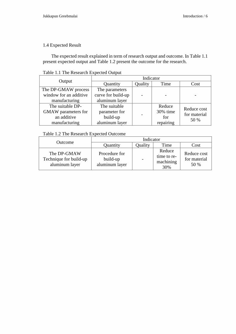
1.4 Expected Result
The expected result explained in term of research output and outcome. In Table 1.1 present expected output and Table 1.2 present the outcome for the research. Table 1.1 The Research Expected Output
Output Indicator Quantity Quality Time Cost
The DP-GMAW process window for an additive
manufacturing
The parameters curve for build-up aluminum layer
- - -
The suitable DP-GMAW parameters for
an additive manufacturing
The suitable parameter for
build-up aluminum layer
-
Reduce 30% time
for repairing
Reduce cost for material
50 %
Table 1.2 The Research Expected Outcome
Outcome Indicator Quantity Quality Time Cost
The DP-GMAW Technique for build-up
aluminum layer
Procedure for build-up
aluminum layer -
Reduce time to re-machining
30%
Reduce cost for material
50 %

Fac. of Grad. Studies, Mahidol Univ. M.Eng. (Industrial Engineering) / 7
LITERATURE REVIEW
For this research focus on double-pulse gas metal arc welding (DP-GMAW) to build-up aluminum layer. The investigated had reviewed with relevant research in the subject as DP-GMAW technology and GMAW in additive manufacturing. 2.1 Double Pulse Gas Metal Arc Welding
The double pulse gas metal arc welding (DP-GMAW) is a gas metal arc welding (GMAW) with double pulse welding current. To operating, the arc welding process is a welding process using wires electrodes from wire rolls which is continuous feeding through the contact tip in a welding torch. The electrode wire is exposed to the base material surface, caused the arc and high temperature that enough to melt the filler wire to flow into the base material surfaces. The continue wire melted as molten pool or weld pool to fill the metal in the workpiece, resulting in the welding bead. The shielding gas is vital to protect the weld pool from ambient to keep the weld quality. Figure 2.1 is a model for illustrated the GMAW process phenomena.
Figure 2.1 Gas Metal Arc Welding
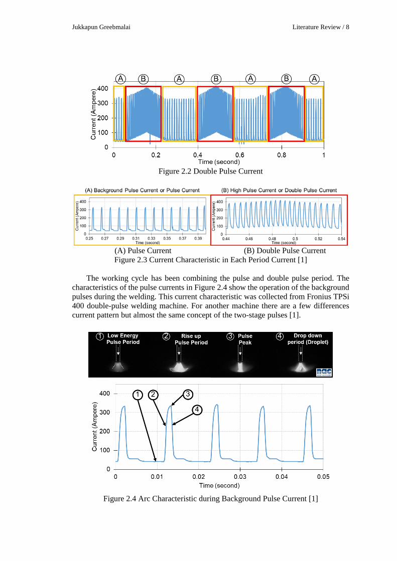
The Double Pulse or Double Pulse Current is a combination of two pulse currents
condition was repeatedly working the double pulse current one second represent in Figure 2.2. The combination consists of (A) Background pulse current or pulse current, shown in Figure 2.3(A). The second current is the (B) Hot pulse current or double pulse current has higher both current and frequency than background current depends on welding machine technology as shown in Figure 2.3(B). The double pulse is combined the two currents into the working cycle.
Jukkapun Greebmalai Literature Review / 8
Figure 2.2 Double Pulse Current
(A) Pulse Current (B) Double Pulse Current Figure 2.3 Current Characteristic in Each Period Current [1]
The working cycle has been combining the pulse and double pulse period. The
characteristics of the pulse currents in Figure 2.4 show the operation of the background pulses during the welding. This current characteristic was collected from Fronius TPSi 400 double-pulse welding machine. For another machine there are a few differences current pattern but almost the same concept of the two-stage pulses [1].
Figure 2.4 Arc Characteristic during Background Pulse Current [1]
Fac. of Grad. Studies, Mahidol Univ. M.Eng. (Industrial Engineering) / 9
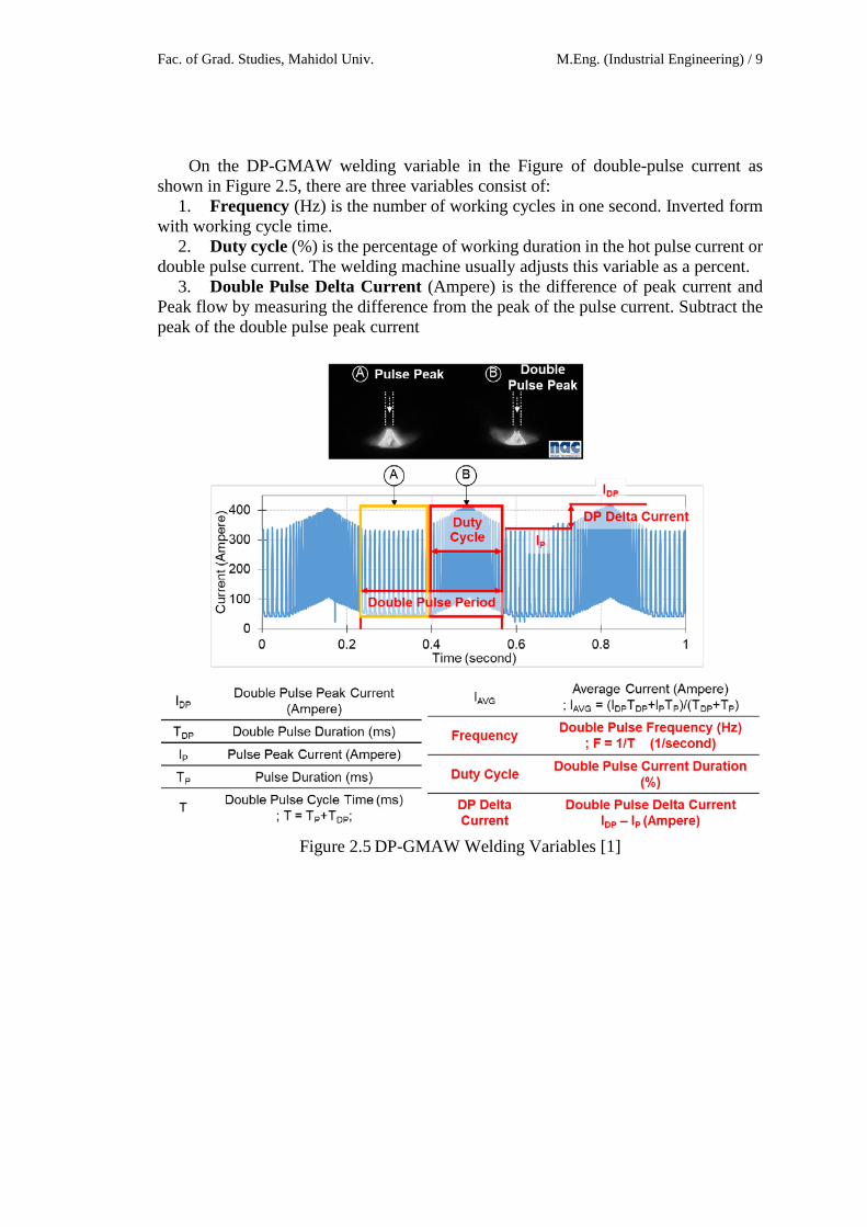
On the DP-GMAW welding variable in the Figure of double-pulse current as shown in Figure 2.5, there are three variables consist of:
1. Frequency (Hz) is the number of working cycles in one second. Inverted form with working cycle time.
2. Duty cycle (%) is the percentage of working duration in the hot pulse current or double pulse current. The welding machine usually adjusts this variable as a percent.
3. Double Pulse Delta Current (Ampere) is the difference of peak current and Peak flow by measuring the difference from the peak of the pulse current. Subtract the peak of the double pulse peak current
Figure 2.5 DP-GMAW Welding Variables [1]
Jukkapun Greebmalai Literature Review / 10
2.2 Wire-Feed Additive Manufacturing For wire laser additive manufacturing (WLAM) processes, the wire feed rate is
limited by the laser power. When the wire feed rate was set at high levels, a wire could not be fully melted. In this case, the wire will be plunged into the melt pool and will be melted partially by the high temperature of the melt pool. Therefore, there is the limitation of the maximum wire feed rate for a specific laser power input. A preferred wire feed rate for the laser power 2.06 and 1.2 kW was chosen as 2 and 1 m/min, respectively, for the deposition of the Ti-based alloy. Deposition rate can be calculated given the wire feed rate and the wire diameter. The reported deposition rate of WLAM varies from 1.5 to 48.0 g/min.
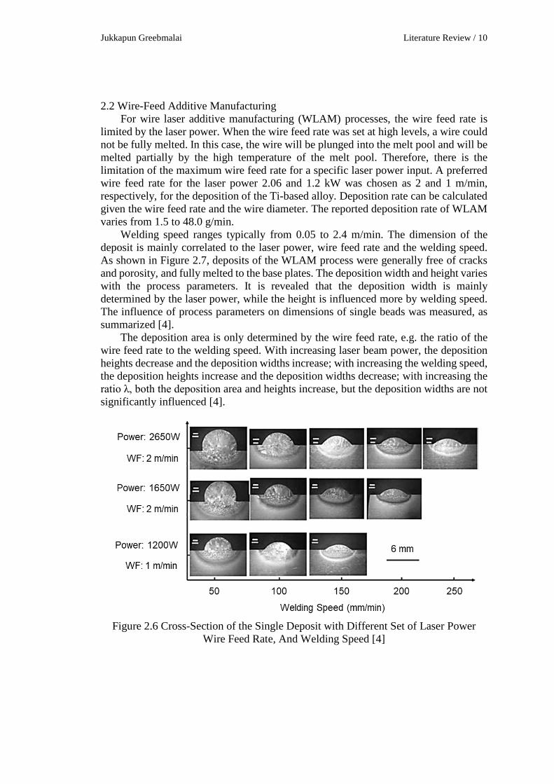
Welding speed ranges typically from 0.05 to 2.4 m/min. The dimension of the deposit is mainly correlated to the laser power, wire feed rate and the welding speed. As shown in Figure 2.7, deposits of the WLAM process were generally free of cracks and porosity, and fully melted to the base plates. The deposition width and height varies with the process parameters. It is revealed that the deposition width is mainly determined by the laser power, while the height is influenced more by welding speed. The influence of process parameters on dimensions of single beads was measured, as summarized [4].
The deposition area is only determined by the wire feed rate, e.g. the ratio of the wire feed rate to the welding speed. With increasing laser beam power, the deposition heights decrease and the deposition widths increase; with increasing the welding speed, the deposition heights increase and the deposition widths decrease; with increasing the ratio λ, both the deposition area and heights increase, but the deposition widths are not significantly influenced [4].
Figure 2.6 Cross-Section of the Single Deposit with Different Set of Laser Power
Wire Feed Rate, And Welding Speed [4]
Fac. of Grad. Studies, Mahidol Univ. M.Eng. (Industrial Engineering) / 11
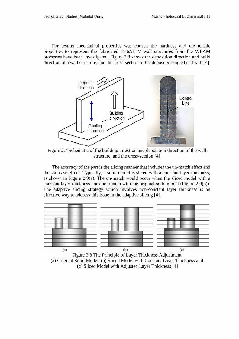
For testing mechanical properties was chosen the hardness and the tensile properties to represent the fabricated Ti-6Al-4V wall structures from the WLAM processes have been investigated. Figure 2.8 shows the deposition direction and build direction of a wall structure, and the cross-section of the deposited single bead wall [4].
Figure 2.7 Schematic of the building direction and deposition direction of the wall
structure, and the cross-section [4]
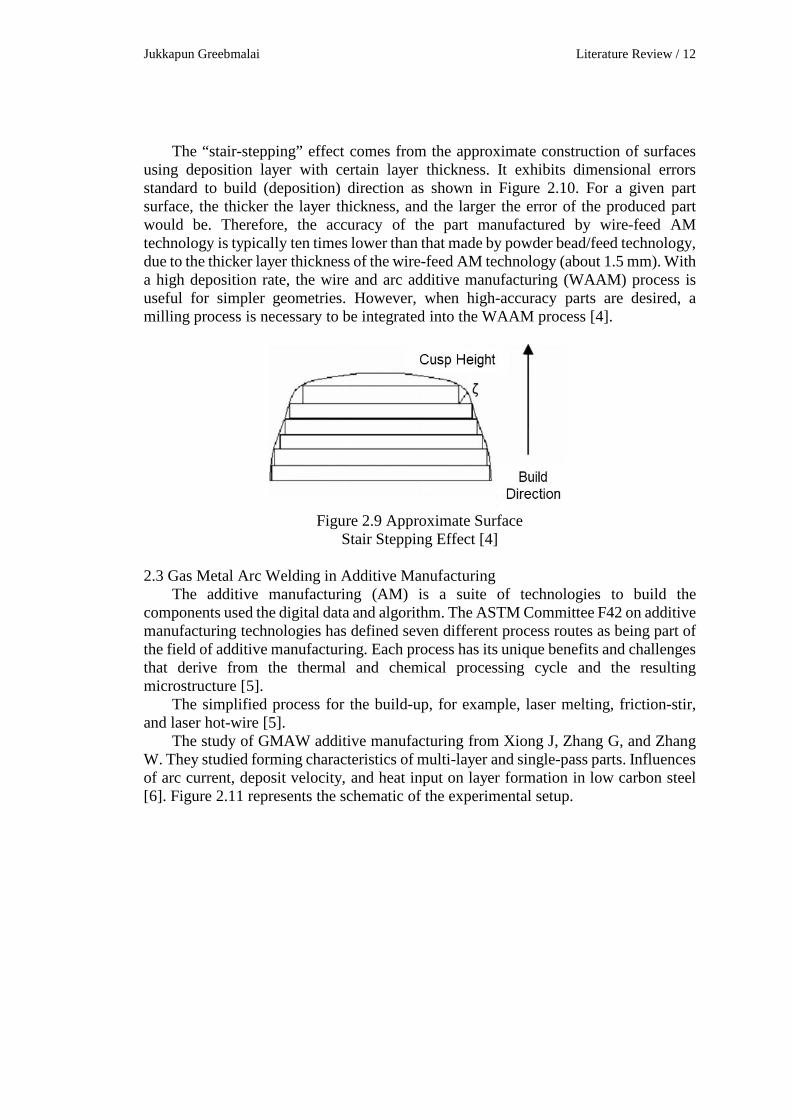
The accuracy of the part is the slicing manner that includes the un-match effect and the staircase effect. Typically, a solid model is sliced with a constant layer thickness, as shown in Figure 2.9(a). The un-match would occur when the sliced model with a constant layer thickness does not match with the original solid model (Figure 2.9(b)). The adaptive slicing strategy which involves non-constant layer thickness is an effective way to address this issue in the adaptive slicing [4].
Figure 2.8 The Principle of Layer Thickness Adjustment
(a) Original Solid Model, (b) Sliced Model with Constant Layer Thickness and (c) Sliced Model with Adjusted Layer Thickness [4]
Jukkapun Greebmalai Literature Review / 12
The “stair-stepping” effect comes from the approximate construction of surfaces using deposition layer with certain layer thickness. It exhibits dimensional errors standard to build (deposition) direction as shown in Figure 2.10. For a given part surface, the thicker the layer thickness, and the larger the error of the produced part would be. Therefore, the accuracy of the part manufactured by wire-feed AM technology is typically ten times lower than that made by powder bead/feed technology, due to the thicker layer thickness of the wire-feed AM technology (about 1.5 mm). With a high deposition rate, the wire and arc additive manufacturing (WAAM) process is useful for simpler geometries. However, when high-accuracy parts are desired, a milling process is necessary to be integrated into the WAAM process [4].
Figure 2.9 Approximate Surface
Stair Stepping Effect [4] 2.3 Gas Metal Arc Welding in Additive Manufacturing
The additive manufacturing (AM) is a suite of technologies to build the components used the digital data and algorithm. The ASTM Committee F42 on additive manufacturing technologies has defined seven different process routes as being part of the field of additive manufacturing. Each process has its unique benefits and challenges that derive from the thermal and chemical processing cycle and the resulting microstructure [5].
The simplified process for the build-up, for example, laser melting, friction-stir, and laser hot-wire [5].
The study of GMAW additive manufacturing from Xiong J, Zhang G, and Zhang W. They studied forming characteristics of multi-layer and single-pass parts. Influences of arc current, deposit velocity, and heat input on layer formation in low carbon steel [6]. Figure 2.11 represents the schematic of the experimental setup.
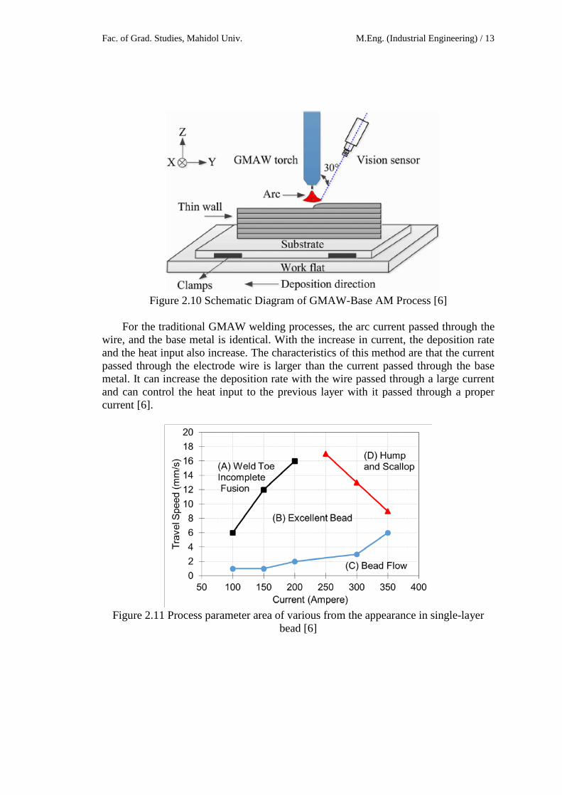
Fac. of Grad. Studies, Mahidol Univ. M.Eng. (Industrial Engineering) / 13
Figure 2.10 Schematic Diagram of GMAW-Base AM Process [6]
For the traditional GMAW welding processes, the arc current passed through the
wire, and the base metal is identical. With the increase in current, the deposition rate and the heat input also increase. The characteristics of this method are that the current passed through the electrode wire is larger than the current passed through the base metal. It can increase the deposition rate with the wire passed through a large current and can control the heat input to the previous layer with it passed through a proper current [6].
Figure 2.11 Process parameter area of various from the appearance in single-layer
bead [6]
Jukkapun Greebmalai Literature Review / 14
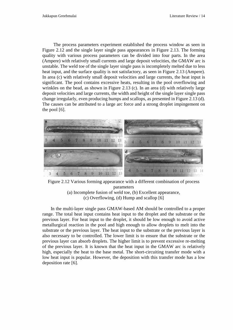
The process parameters experiment established the process window as seen in Figure 2.12 and the single layer single pass appearances in Figure 2.13. The forming quality with various process parameters can be divided into four parts. In the area (Ampere) with relatively small currents and large deposit velocities, the GMAW arc is unstable. The weld toe of the single layer single pass is incompletely melted due to less heat input, and the surface quality is not satisfactory, as seen in Figure 2.13 (Ampere). In area (c) with relatively small deposit velocities and large currents, the heat input is significant. The pool contains excessive heats, resulting in the pool overflowing and wrinkles on the bead, as shown in Figure 2.13 (c). In an area (d) with relatively large deposit velocities and large currents, the width and height of the single layer single pass change irregularly, even producing humps and scallops, as presented in Figure 2.13 (d). The causes can be attributed to a large arc force and a strong droplet impingement on the pool [6].
Figure 2.12 Various forming appearance with a different combination of process
parameters (a) Incomplete fusion of weld toe, (b) Excellent appearance,
(c) Overflowing, (d) Hump and scallop [6]
In the multi-layer single pass GMAW-based AM should be controlled to a proper range. The total heat input contains heat input to the droplet and the substrate or the previous layer. For heat input to the droplet, it should be low enough to avoid active metallurgical reaction in the pool and high enough to allow droplets to melt into the substrate or the previous layer. The heat input to the substrate or the previous layer is also necessary to be controlled. The lower limit is to ensure that the substrate or the previous layer can absorb droplets. The higher limit is to prevent excessive re-melting of the previous layer. It is known that the heat input in the GMAW arc is relatively high, especially the heat to the base metal. The short-circuiting transfer mode with a low heat input is popular. However, the deposition with this transfer mode has a low deposition rate [6].
Fac. of Grad. Studies, Mahidol Univ. M.Eng. (Industrial Engineering) / 15
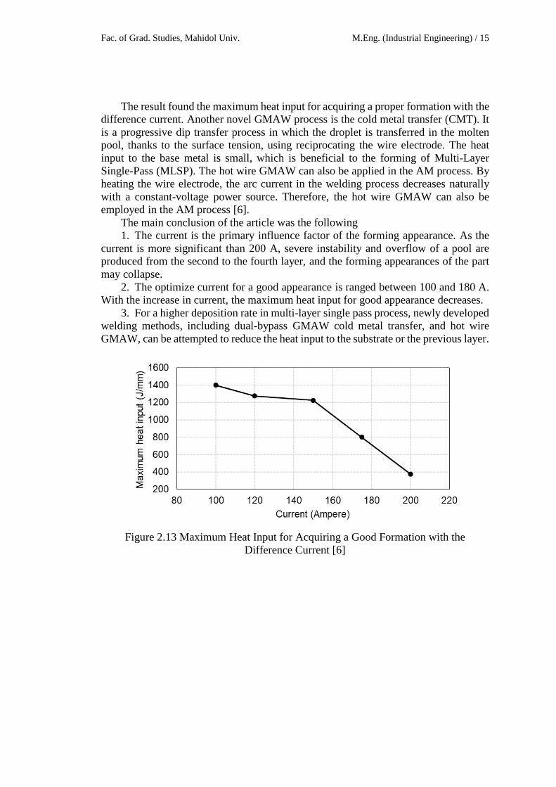
The result found the maximum heat input for acquiring a proper formation with the difference current. Another novel GMAW process is the cold metal transfer (CMT). It is a progressive dip transfer process in which the droplet is transferred in the molten pool, thanks to the surface tension, using reciprocating the wire electrode. The heat input to the base metal is small, which is beneficial to the forming of Multi-Layer Single-Pass (MLSP). The hot wire GMAW can also be applied in the AM process. By heating the wire electrode, the arc current in the welding process decreases naturally with a constant-voltage power source. Therefore, the hot wire GMAW can also be employed in the AM process [6].
The main conclusion of the article was the following 1. The current is the primary influence factor of the forming appearance. As the
current is more significant than 200 A, severe instability and overflow of a pool are produced from the second to the fourth layer, and the forming appearances of the part may collapse.
2. The optimize current for a good appearance is ranged between 100 and 180 A. With the increase in current, the maximum heat input for good appearance decreases.
3. For a higher deposition rate in multi-layer single pass process, newly developed welding methods, including dual-bypass GMAW cold metal transfer, and hot wire GMAW, can be attempted to reduce the heat input to the substrate or the previous layer.
Figure 2.13 Maximum Heat Input for Acquiring a Good Formation with the
Difference Current [6]
Jukkapun Greebmalai Literature Review / 16
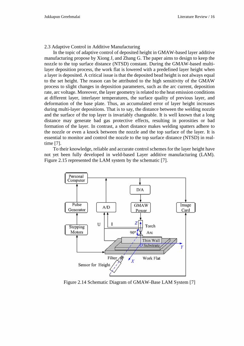
2.3 Adaptive Control in Additive Manufacturing In the topic of adaptive control of deposited height in GMAW-based layer additive
manufacturing propose by Xiong J, and Zhang G. The paper aims to design to keep the nozzle to the top surface distance (NTSD) constant. During the GMAW-based multi-layer deposition process, the work flat is lowered with a predefined layer height when a layer is deposited. A critical issue is that the deposited bead height is not always equal to the set height. The reason can be attributed to the high sensitivity of the GMAW process to slight changes in deposition parameters, such as the arc current, deposition rate, arc voltage. Moreover, the layer geometry is related to the heat emission conditions at different layer, interlayer temperatures, the surface quality of previous layer, and deformation of the base plate. Thus, an accumulated error of layer height increases during multi-layer depositions. That is to say, the distance between the welding nozzle and the surface of the top layer is invariably changeable. It is well known that a long distance may generate bad gas protective effects, resulting in porosities or bad formation of the layer. In contrast, a short distance makes welding spatters adhere to the nozzle or even a knock between the nozzle and the top surface of the layer. It is essential to monitor and control the nozzle to the top surface distance (NTSD) in real-time [7].
To their knowledge, reliable and accurate control schemes for the layer height have not yet been fully developed in weld-based Layer additive manufacturing (LAM). Figure 2.15 represented the LAM system by the schematic [7].
Figure 2.14 Schematic Diagram of GMAW-Base LAM System [7]
Fac. of Grad. Studies, Mahidol Univ. M.Eng. (Industrial Engineering) / 17
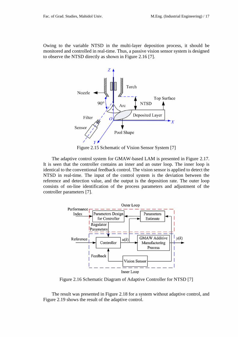
Owing to the variable NTSD in the multi-layer deposition process, it should be monitored and controlled in real-time. Thus, a passive vision sensor system is designed to observe the NTSD directly as shown in Figure 2.16 [7].
Figure 2.15 Schematic of Vision Sensor System [7]
The adaptive control system for GMAW-based LAM is presented in Figure 2.17.
It is seen that the controller contains an inner and an outer loop. The inner loop is identical to the conventional feedback control. The vision sensor is applied to detect the NTSD in real-time. The input of the control system is the deviation between the reference and detection value, and the output is the deposition rate. The outer loop consists of on-line identification of the process parameters and adjustment of the controller parameters [7].
Figure 2.16 Schematic Diagram of Adaptive Controller for NTSD [7]
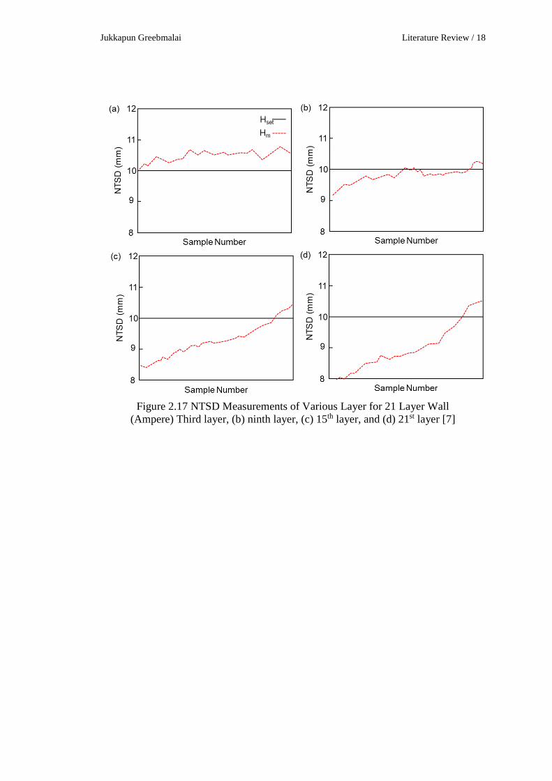
The result was presented in Figure 2.18 for a system without adaptive control, and Figure 2.19 shows the result of the adaptive control.
Jukkapun Greebmalai Literature Review / 18
Figure 2.17 NTSD Measurements of Various Layer for 21 Layer Wall
(Ampere) Third layer, (b) ninth layer, (c) 15th layer, and (d) 21st layer [7]

Fac. of Grad. Studies, Mahidol Univ. M.Eng. (Industrial Engineering) / 19
Figure 2.18 Adaptive Control Result of Difference Layer
(Ampere) Third layer, (b) ninth layer, (c) 15th layer, and (d) 21st layer [7]
The conclusion of adaptive control of deposited height in GMAW-based layer additive manufacturing is a passive vision sensor system, and a process controller for layer height have been developed and estimated through deposition of single-bead multi-layer walls in GMAW-based LAM. The major conclusions are generalized as follows [7].
1. The passive vision sensor is sufficient for monitoring the nozzle to the top surface distance. Clear deposition bead images are obtained.
2. Image processing algorithms, including Gaussian filter, Sobel operator, and Hough transformation, were proposed to extract the NTSD in the image accurately.
3. An adaptive controller using adjusting the deposition rate is introduced to keep the NTSD constant. The precision range of the control system is limited within ±0.5 mm.
4. New control strategies for arc starting and stopping points need to be developed to eliminate the height deviation.

Jukkapun Greebmalai Research Methodology / 20
RESEARCH METHODOLOGY
3.1 Research Methodology
The research methodology follows four majority sections including to first the DP-GMAW parameters study, second multi-layer study, third curvature-path study, finally the process optimization and applicable process window construction Figure 3.1 below was presented the progression of research methodology.
Figure 3.1 Research Methodology
Fac. of Grad. Studies, Mahidol Univ. M.Eng. (Industrial Engineering) / 21
To build-up the aluminum layer, the first study is single-pass bead on plate to study DP-GMAW parameters in order to understand the effect of DP-GMAW parameters which affect the build-up dimension. The welding parameter is most vital to creating the dimension. In this section focus on five of DP-GMAW being arc voltage, arc current, frequency, duty cycle, and delta current. By setting the parameters, the weld dimension had measured to represents the effect of the welding parameter on weld dimension.
The multi-layer build-up parameters study focuses on build-up step height distance and surface temperature under effect of DP-GMAW parameters to understanding the influence of build-up step height distance and surface temperature to build-up the laminate layer dimension for construct the process window by study parameters. The temperature under the effect of DP-GMAW for the multi-layer condition was measured by the thermocouple and the infrared camera.
The curvature-path build-up study is including to the curvature radius and travel or build-up speed to determine the effect on the build-up size dimension using the parameters curve function. In this step had determined the minimum radius for the arc path.
In the last section of research focusing on the process optimization, the previous study parameters were optimized. To create the build-up layer criterion on maximize bead height and minimizing bead width in order to the height represents the productivity of the process. The build-up had high build-up rate and low heat input for multi-layer build-up.
In each progression of the research performed to evaluate the weld bead for single pass build-up and multi-layer build-up is used welding visualization system and system for collecting welding parameters characteristic. The weld bead dimension and build-up laminate layer dimension used visual inspection, direct measure, image processing measure and metallography cross-section for evaluating. The radiographic testing or x-ray has had used to testing and evaluating the soundness of the multi-layer wall to inspected the imperfection of the laminate layer.
3.2 Materials and Equipment
Material Base material and build-up material was used in aluminum alloy five thousand
series aluminum-magnesium alloy (Al-Mg alloy). The base or substrate material had chosen aluminum 5052. The build-up material had chosen aluminum filler wire 5356 (AL-5356) diameters 1.2 millimeters the chemical composition represented in Table 4.1. The GMAW process shielding gas was used an industrial grade argon gas (Purity > 99%).
Jukkapun Greebmalai Research Methodology / 22
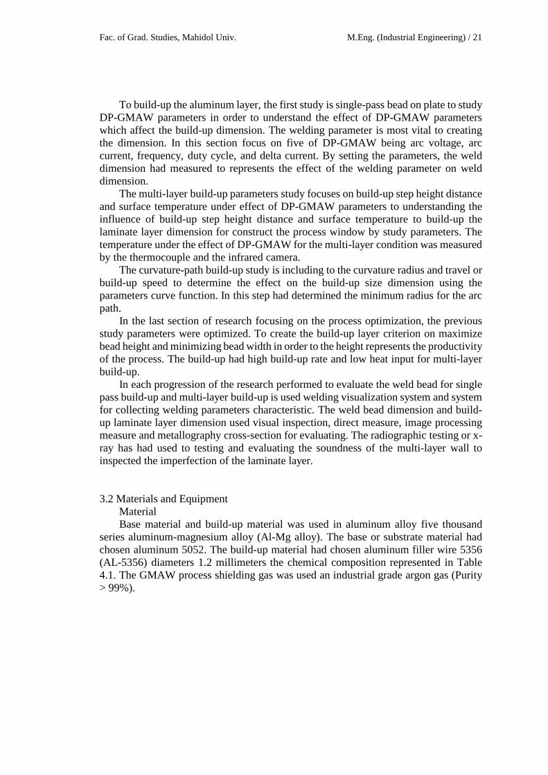
Table 3.1 Chemical Composition of for Build-up Layer [8, 9] Chemical Component (% Weight)
Component Base Material Al-5052
Build-up Material Al-5356
Aluminum Reminder Reminder
Chromium 0.15 – 0.35 0.05 – 0.20
Copper Max 0.10 Max 0.10
Iron Max 0.40 Max 0.40
Magnesium 2.20 – 2.80 4.50 – 5.50
Manganese Max 0.10 0.50 – 0.20
Silicon Max 0.25 Max 0.25
Titanium - 0.60 – 0.20
Zinc Max 0.10 Max 0.10
Beryllium - Max 0.0003
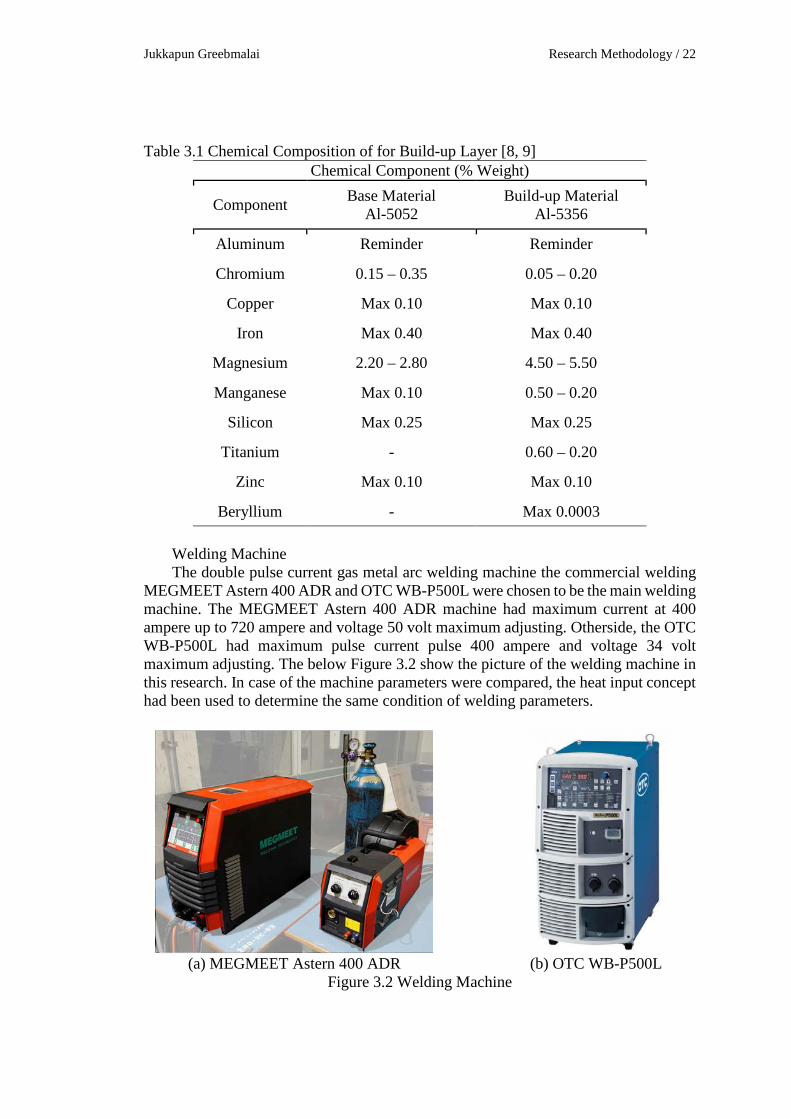
Welding Machine The double pulse current gas metal arc welding machine the commercial welding
MEGMEET Astern 400 ADR and OTC WB-P500L were chosen to be the main welding machine. The MEGMEET Astern 400 ADR machine had maximum current at 400 ampere up to 720 ampere and voltage 50 volt maximum adjusting. Otherside, the OTC WB-P500L had maximum pulse current pulse 400 ampere and voltage 34 volt maximum adjusting. The below Figure 3.2 show the picture of the welding machine in this research. In case of the machine parameters were compared, the heat input concept had been used to determine the same condition of welding parameters.
(a) MEGMEET Astern 400 ADR
(b) OTC WB-P500L
Figure 3.2 Welding Machine
Fac. of Grad. Studies, Mahidol Univ. M.Eng. (Industrial Engineering) / 23
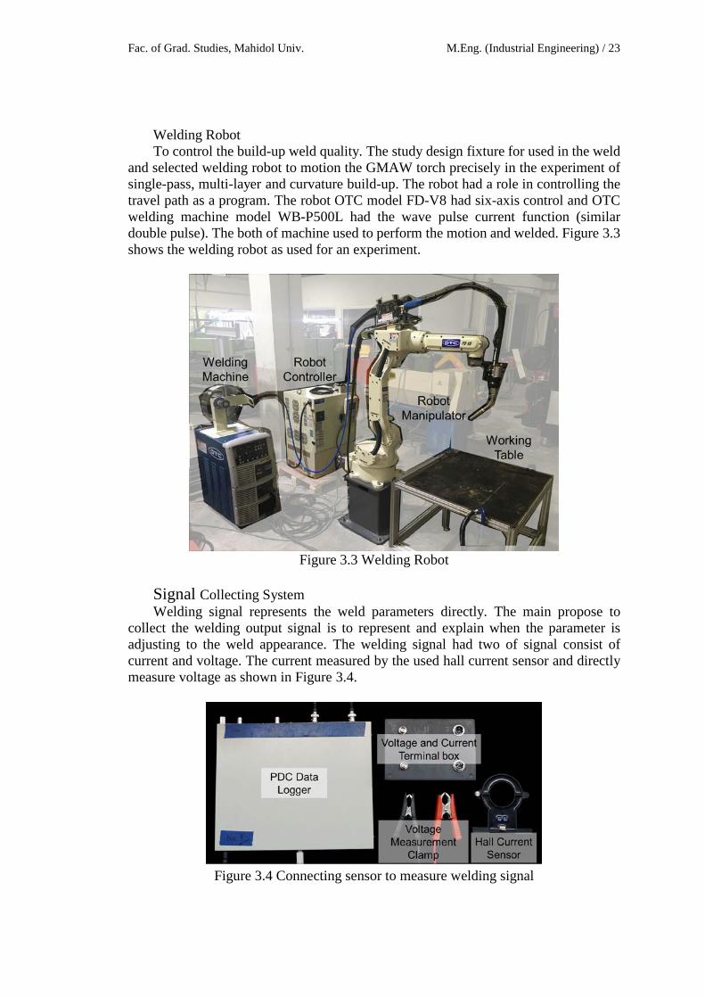
Welding Robot To control the build-up weld quality. The study design fixture for used in the weld
and selected welding robot to motion the GMAW torch precisely in the experiment of single-pass, multi-layer and curvature build-up. The robot had a role in controlling the travel path as a program. The robot OTC model FD-V8 had six-axis control and OTC welding machine model WB-P500L had the wave pulse current function (similar double pulse). The both of machine used to perform the motion and welded. Figure 3.3 shows the welding robot as used for an experiment.
Figure 3.3 Welding Robot
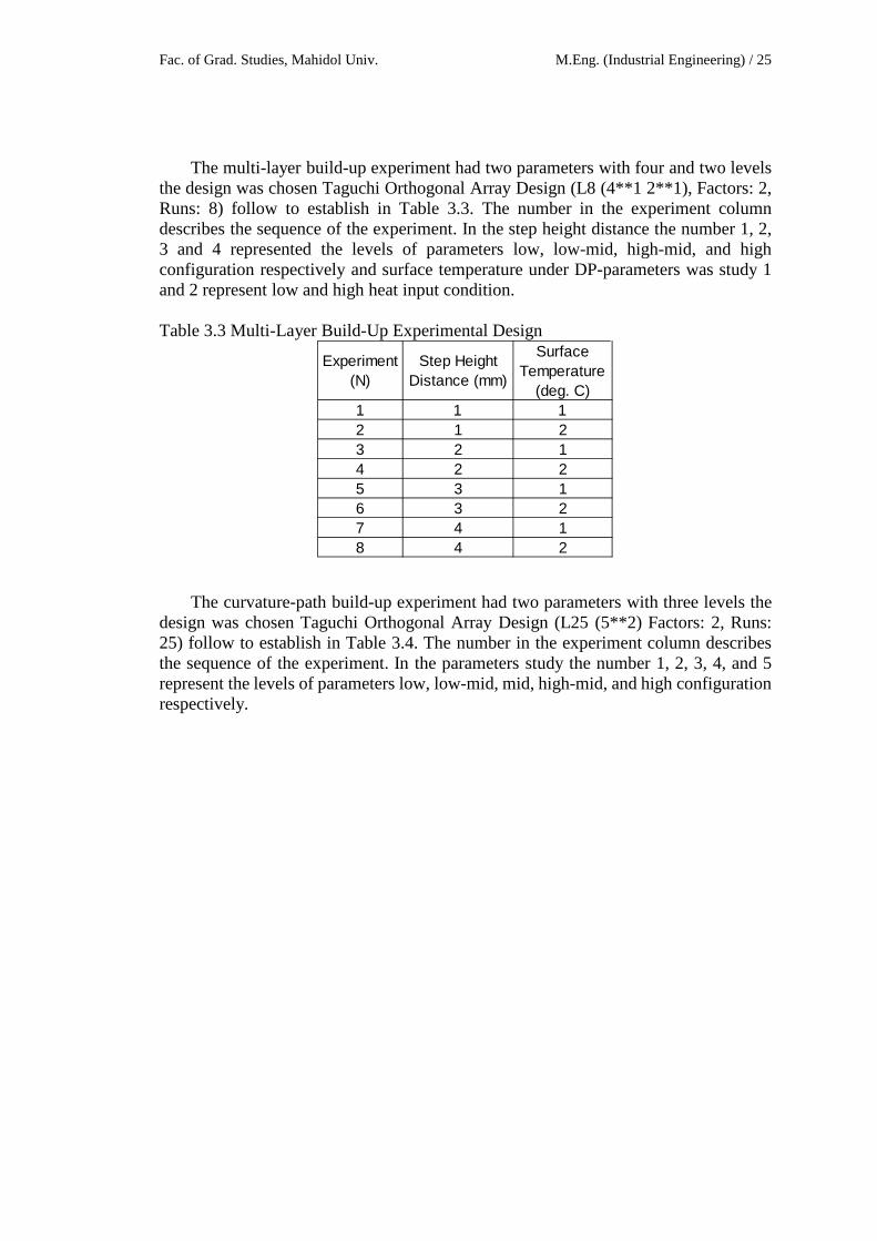
Signal Collecting System Welding signal represents the weld parameters directly. The main propose to
collect the welding output signal is to represent and explain when the parameter is adjusting to the weld appearance. The welding signal had two of signal consist of current and voltage. The current measured by the used hall current sensor and directly measure voltage as shown in Figure 3.4.
Figure 3.4 Connecting sensor to measure welding signal

Jukkapun Greebmalai Research Methodology / 24
3.3 Experimental Design and Setup Experimental Design
The research experiment performed to investigate the effect of the parameter to build-up property. The Taguchi's design was selected to design the experiment because the design could response the effect of parameters and robust with the lowest number of an experiment. Moreover, the optimal combination of the parameter can be determined. In the first experiment had six parameters with three levels the design was chosen Taguchi Orthogonal Array Design (L27 (3**6) Factors: 6, Runs: 27) follow to establish in Table 3.2. The number in the experiment column describes the sequence of the experiment. In the parameters study the number 1, 2, and 3 represent the levels of parameters low, mid, and high configuration respectively. Table 3.2 Single-Pass Build-Up Experimental Design
Experiment(N)
Current(Ampere)
Voltage(Volt)
Travel Speed (cm/min)
Frequency(Hz)
Duty Cycle(%)
Delta Current(Ampere)
1 1 1 1 1 1 12 1 1 1 1 2 23 1 1 1 1 3 34 1 2 2 2 1 15 1 2 2 2 2 26 1 2 2 2 3 37 1 3 3 3 1 18 1 3 3 3 2 29 1 3 3 3 3 3
10 2 1 2 3 1 211 2 1 2 3 2 312 2 1 2 3 3 113 2 2 3 1 1 214 2 2 3 1 2 315 2 2 3 1 3 116 2 3 1 2 1 217 2 3 1 2 2 318 2 3 1 2 3 119 3 1 3 2 1 320 3 1 3 2 2 121 3 1 3 2 3 222 3 2 1 3 1 323 3 2 1 3 2 124 3 2 1 3 3 225 3 3 2 1 1 326 3 3 2 1 2 127 3 3 2 1 3 2
Fac. of Grad. Studies, Mahidol Univ. M.Eng. (Industrial Engineering) / 25
The multi-layer build-up experiment had two parameters with four and two levels the design was chosen Taguchi Orthogonal Array Design (L8 (4**1 2**1), Factors: 2, Runs: 8) follow to establish in Table 3.3. The number in the experiment column describes the sequence of the experiment. In the step height distance the number 1, 2, 3 and 4 represented the levels of parameters low, low-mid, high-mid, and high configuration respectively and surface temperature under DP-parameters was study 1 and 2 represent low and high heat input condition. Table 3.3 Multi-Layer Build-Up Experimental Design
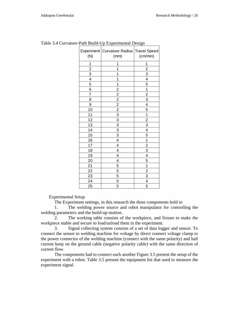
The curvature-path build-up experiment had two parameters with three levels the design was chosen Taguchi Orthogonal Array Design (L25 (5**2) Factors: 2, Runs: 25) follow to establish in Table 3.4. The number in the experiment column describes the sequence of the experiment. In the parameters study the number 1, 2, 3, 4, and 5 represent the levels of parameters low, low-mid, mid, high-mid, and high configuration respectively.
Experiment(N)
Step Height Distance (mm)
Surface Temperature
(deg. C)1 1 12 1 23 2 14 2 25 3 16 3 27 4 18 4 2
Jukkapun Greebmalai Research Methodology / 26
Table 3.4 Curvature-Path Build-Up Experimental Design
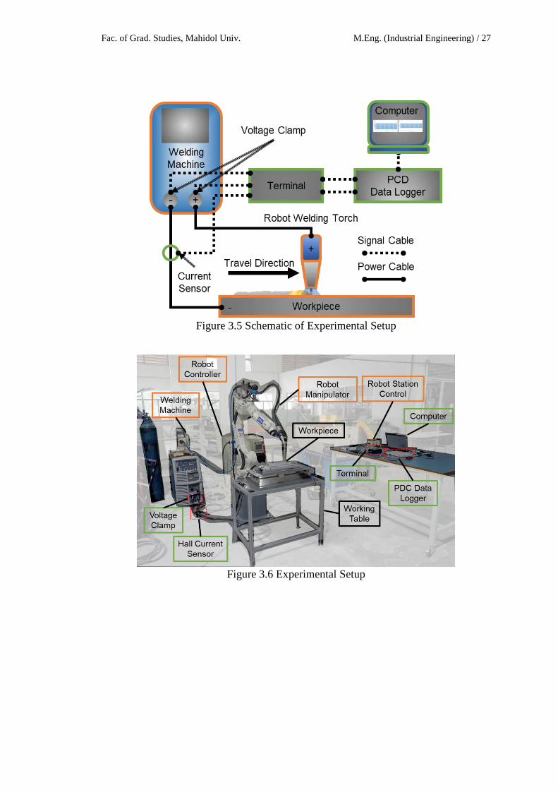
Experimental Setup The Experiment settings, in this research the three components hold to 1. The welding power source and robot manipulator for controlling the
welding parameters and the build-up motion. 2. The working table consists of the workpiece, and fixture to make the
workpiece stable and secure to load/unload them in the experiment. 3. Signal collecting system consists of a set of data logger and sensor. To
connect the sensor to welding machine for voltage by direct connect voltage clamp to the power connector of the welding machine (connect with the same polarity) and hall current keep on the ground cable (negative polarity cable) with the same direction of current flow.
The components had to connect each another Figure 3.5 present the setup of the experiment with a robot. Table 3.5 present the equipment list that used to measure the experiment signal.
Experiment(N)
Curvature Radius(mm)
Travel Speed (cm/min)
1 1 12 1 23 1 34 1 45 1 56 2 17 2 28 2 39 2 4
10 2 511 3 112 3 213 3 314 3 415 3 516 4 117 4 218 4 319 4 420 4 521 5 122 5 223 5 324 5 425 5 5
Fac. of Grad. Studies, Mahidol Univ. M.Eng. (Industrial Engineering) / 27
Figure 3.5 Schematic of Experimental Setup
Figure 3.6 Experimental Setup
Jukkapun Greebmalai Research Methodology / 28
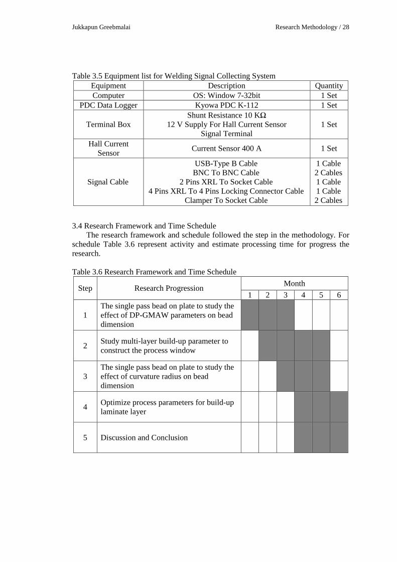
Table 3.5 Equipment list for Welding Signal Collecting System Equipment Description Quantity Computer OS: Window 7-32bit 1 Set
PDC Data Logger Kyowa PDC K-112 1 Set
Terminal Box Shunt Resistance 10 KΩ
12 V Supply For Hall Current Sensor Signal Terminal
1 Set
Hall Current Sensor Current Sensor 400 A 1 Set
Signal Cable
USB-Type B Cable BNC To BNC Cable
2 Pins XRL To Socket Cable 4 Pins XRL To 4 Pins Locking Connector Cable
Clamper To Socket Cable
1 Cable 2 Cables 1 Cable 1 Cable 2 Cables
3.4 Research Framework and Time Schedule The research framework and schedule followed the step in the methodology. For
schedule Table 3.6 represent activity and estimate processing time for progress the research. Table 3.6 Research Framework and Time Schedule
Step Research Progression Month 1 2 3 4 5 6
1 The single pass bead on plate to study the effect of DP-GMAW parameters on bead dimension
2 Study multi-layer build-up parameter to construct the process window
3 The single pass bead on plate to study the effect of curvature radius on bead dimension
4 Optimize process parameters for build-up laminate layer
5 Discussion and Conclusion
Fac. of Grad. Studies, Mahidol Univ. M.Eng. (Industrial Engineering) / 29
REFERENCES [1] Warinsiriruk E, Greebmalai J, Sangsuriyun M. Effect of Double Pulse MIG
Welding on Porosity Formation on Aluminum 5083 Fillet Joint. IIW2018 (A1) - Welding Technology; 2018
[2] Joshua OS, David MO, Sikiru IO. Experimental Investigation of Cutting Parameters on Surface Roughness Prediction during End Milling of Aluminium 6061 under MQL (Minimum Quantity Lubrication). Journal of Mechanical Engineering and Automation. 2015;5(1):1-3.
[3] TOMIDA S. Alloying of Aluminum Surface by Laser. Journal of The Surface Finishing Society of Japan. 1992 Mar 1;43(3):181-7.
[4] Ding D, Pan Z, Cuiuri D, Li H. Wire-feed additive manufacturing of metal components: technologies, developments and future interests. The International Journal of Advanced Manufacturing Technology. 2015 Oct 1;81(1-4):465-81.
[5] Herderick ED. Progress in additive manufacturing. JOM. 2015 Mar 1;67(3):580-1.
[6] Xiong J, Zhang G, Zhang W. Forming appearance analysis in multi-layer single-pass GMAW-based additive manufacturing. The International Journal of Advanced Manufacturing Technology. 2015 Oct 1;80(9-12):1767-76.
[7] Xiong J, Zhang G. Adaptive control of deposited height in GMAW-based layer additive manufacturing. Journal of Materials Processing Technology. 2014 Apr 1;214(4):962-8.
[8] AZoM. Aluminum 5356 Alloy (UNS A95356). https://www.azom.com/article.aspx?ArticleID=6654 (accessed Oct 2018).
[9] AZoM. Aluminium / Aluminum 5052 Alloy (UNS A95052). https://www.azom.com/article.aspx?ArticleID=6626accessed Oct 2018).