Embed Size (px)
Citation preview

THE DIGITAL MAPPING CAMERA DMC AND ITS APPLICATION POTENTIAL
R. W. Schroth
Hansa Luftbild Group, Elbestr. 5, 48145 Muenster, Germany - [email protected]
Commission I, WG I/5 and IV, IV/3
KEY WORDS: Operability, Modularity, Geometry, Radiometry, Large Format Digital Cameras
ABSTRACT:
The Hansa Luftbild Group decided in summer 2005 to purchase the Digital Mapping Camera (DMC) of Z/I Imaging (Intergraph)
and is operating this system since February 2006. Up to now there was about 300 hours of aerial survey flights flown and about
30.000 images processed. Additional experiences exist with other large format cameras.
This paper will first give some information about the technical and financial processes of evaluation of the digital large format
camera for aerial surveys. In the second part, the configuration of the system as it was chosen by Hansa Luftbild will be explained.
The emphasis will be laid on the installation of the system in different kind of survey planes. The handling of the amount of data and
the image post-processing are challenging tasks which demand a strict workflow and an integration into the complete project
management workflow. Solutions for intermediate quality checks have been established and some are still under preparation.
Experiences about geometric and radiometric quality and calibration procedures can be demonstrated in the real production
environment. The full potential of the DMC system is demonstrated at several applications.
RÉSUMÉ :
Le Groupe Hansa Luftbild a décidé à l’été 2005 d’acheter une caméra numérique DMC de Z/I Imaging (Intergraph) et utilise ce
système depuis février 2006. Jusqu’à mars 2007, 300 heures de vol ont été effectuées et environ 30.000 images ont été traitées. Des
expériences additionnelles ont aussi été effectuées avec d’autres caméras à grand format.
Cet article donnera premièrement de l’information sur les procédés d’évaluation technique et financière de la caméra numérique
grand format pour les levées aériennes. Dans la deuxième partie, la configuration du système choisie par Hansa Luftbild sera
expliquée. L’emphase sera mise sur l’installation du système dans différents avions. La manipulation de la quantité de données et le
traitement des images sont des taches difficiles demandant un processus strict et une intégration dans le processus complet de gestion
de projet. Des solutions pour le contrôle intermédiaire de la qualité ont été développées et d’autres sont en préparation.
Finalement, les résultats d’expériences sur la qualité de la géométrie et de la radiométrie dans un environnement réel seront exposés.
1. INTRODUCTION
The workflow of the photogrammetric production from the
analytical to the digital processing started to change about 20
years ago with the introduction of the first digital
photogrammetric stereo workstations. High precision film
scanners followed with efficient productivity by auto winding
systems. So it was only consequent when at the ISPRS
Congress 2000 in Amsterdam the first large format digital aerial
survey camera was introduced by Leica (see Sandau et al.,
2000). Since that date mainly three major suppliers are
dominating the market of the large format camera systems.
Although there are more and more medium format cameras
(about 40 Megapixels) using color CCD sensors based on the
Bayer-pattern filter for reasons of geometric and radiometric
precision here there will be a restriction for the multispectral
approach.
The Hansa Luftbild Group got already 10 years ago first
experiences about digital camera systems with a color line
scanning system. Due to the limited format of the CCD line the
applications were very restricted. In 2002 an EU IST research
project entitled “GEOPIE – Geo-Referencing via Parallel Image
Engineering“ started and some more experiences during the
project phase of 2 years could be gathered with a sophisticated
combination of small CCD arrays (see Mayr/Ohlhof, 2004).
Further more since 2003 began the use of the medium format
camera system Emerge integrated into a LiDAR system. Also,
here the restrictions of the quite small array format for small
areas led to the demand of a large format digital camera system.
At the end of the year 2004 Hansa Luftbild decided on a
technical evaluation of the existing digital large format camera
systems (see Mayr, 2004).
2. EVALUATION PHASE
In the year 2004 there were only 3 large format systems on the
market originating from major suppliers: ADS40 (Leica),
UltraCAM-D (Vexcel) and DMC (Z/I Imaging). Consequently,
the evaluation concentrated mainly on these systems, although
other systems like 3-DAS (GeoSystem, see Wehrli et al., 2004)
and DiMAC were taken into consideration initially. Besides
some very detailed technical aspects the main criteria for the
evaluation were:
- Line Scanner vs. Frame technology
- Market research
- Internal and external workflow
- Technical criteria
- Technical evaluation
- Compatibility to existing flight configuration

- Compatibility to existing internal workflow
- Return on investment
- Investment plan
- Financing
- Economic aspects – break even point
A market research found that 80% of the aerial survey flights
undertaken for our clients are for their own production and the
vast majority of our clients clearly prefers frame technology.
Their argument mainly was their own production process
coming from traditional analytical photogrammetry. The same
appeared to our own internal production workflow. Also, all
existing software here is based on frame images, and a change
of the whole system would end up in high additional
investments, as well financially, operationally and
educationally.
On the technical side the criteria of compatibility with respect to
our existing environment in 6 of our aerial survey planes under
use were very important. An easy exchange of sensor equipment
must be guaranteed. As the company operates since decades
systems from the former supplier Zeiss the best compatibility
was given with the DMC from Z/I Imaging - Intergraph. The
technical evaluation took also the quality of the images into
account. But as this topic was a matter of permanent changes in
the calibration and post processing procedures an evaluation
was quite difficult. During the year 2005 about 20.000 digital
images of the large format camera system UltraCAM-D could
be processed for aerial triangulation and the production of
digital orthophoto mosaics, and this brought a lot of experiences
too.
Ground coverage with same GSD was another evaluation
criterion. Here, UltraCAM-D covers 80% of the DMC’s ground
coverage, which results in an economical disadvantage.
The final evaluation step was the determination of the return on
investment and the break even point. As well a comparison
between the analog and the digital camera system was done.
The analysis under the assumption of use of film material, film
processing, film scanning, etc came to the result that the break
even point is at about 150 h of use of the camera system per
year. The investment is not only restricted to the camera system.
The necessary computer hardware for data processing and
storage, the high speed data network, the back-up systems, etc
and the total costs for training have to be added. In total the
relation between the investments in camera system, computer
hardware and training was about 7:2:1.
After the decision for the DMC system the contractual
negotiations with the supplier started and the following
schedule was realized:
- Sep 2005 signature of the contract
- Nov 2005 installation of processing system and
training
- Dec 2005 delivery of the DMC and first test flight
- Jan 2006 camera training phase
- Feb 2006 start of production phase
A technical description of the camera system can be found in
Hinz et al., 2001, Dörstel, 2003 and first results in Schroth,
2007a.
3. CONFIGURATION
The general configuration of the aerial survey system is shown
in figure 1. It is modular and consists of the navigation and
flight guidance system CCNS4 (IGI), the inertial measurement
unit AeroControl (IGI), the differential GPS and the DMC (Z/I
Imaging, Intergraph) with the stabilized mount TA-S (Z/I
Imaging, Intergraph). The modularity is important because other
sensors like analog aerial survey cameras, LiDAR, thermal
sensors etc have to be repeatedly and project dependent
installed into the survey planes.
Figure 1. System configuration with flight navigation system
CCNS4 (IGI), GPS/INS (IGI), DMC (Intergraph)
Digital images are stored during flight mission in the so called
flight data storage system (FDS) comprising 3 storage devices
with a total capacity of about 2.200 images. The capacity is
more than enough for one day of survey flight. After each day
the FDS is copied via the copy station, a computer with a fast
I/O bus system and prepared for a rough environment. For
safety reasons all the data are copied independently twice onto
hard disks. These hard disks are copied via fire wire 800
connection later on in the office to the image server system, a
data storage system with a capacity of more than 100 TB on
RAID array systems. Figure 2 shows the appropriate devices.
Figure 2. Data flow from flight data storage system via copy
station to image server
For the post processing of the raw image data a high
performance server is available. One can remote control it via
internet using a VNC terminal connection. The post processing
server is equipped with 4 processors to speed up the processing
time (see Dörstel et al., 2005). Our analysis of the processors,
however, showed that only two of them are in use during the
processing time. This leads to the assumption that the current
version of the post processing software (PPS) is not designed
for a multi-processor system. The intermediate images are
stored on a raid array system connected to the PPS server. The
final panchromatic, rgb- and CIR-images are delivered to the
image server via fiber channels. All servers are connected by
parallel GigaBit switches (4-times). The image server controls

the data storage in the storage area network (SAN) with several
RAID systems. Figure 3 shows a graphical description of this
configuration. For backup two tape robot systems, based on
LTO-3 tapes are integrated, each equipped with 36 slots. To
speed up the data transfer rate the upgrade to a 10 GigaBit
network is planned for 2007.
Figure 3. Processing and storage network of DMC post
processing
The processing time for the complete post processing of the raw
image data to the final image data varies between 2 and 3
minutes per image under this configuration. This means for
2.000 images with an average processing time of 2,5 minutes
the pure processing time is 80 hours or about 3 days (which, by
the way, is less than the classical film development plus
scanning). With all the preparatory work, adjustments, testing,
etc one can estimate one complete week for the whole
procedure. For the purpose of on-site evaluation and
determination of the final images, e.g. in remote areas, a second
PPS license is available on the mobile copy station.
A quality control procedure accompanies the whole workflow
of the image generation. During the aerial survey flight the
storage of the image data onto the FDS is controlled and quick
view images are checked on a notebook. After the arrival the
images are checked again with the FDS viewer software and
some sample images are processed on the copy station. For the
post processing procedure the image information is
automatically prepared out of the CCNS4 information by a self
developed process to avoid mismatching problems in the
numbering system etc. After the post processing of the images a
first radiometric check will be done. In a further check the flight
operator is producing the flight reports. Besides the radiometry
the parameters of side lap and end lap, the drift and the image
quality are controlled. The quality check of the GPS/INS data
will be done during the adjustment process for generating the
parameters of the exterior orientation.
4. EXPERIENCES AND PRACTICAL APPLICATIONS
Since February 2006 the DMC system was permanently under
use. It produced 30.000 images till March 2007 and executed
more than 300 hours of aerial survey flights. The camera has
been operated in Germany, The Netherlands, Belgium, France,
Spain, Italy, Austria and Romania. During this time there was
only one electronic failure with a power supply unit which
caused a one day repair at Z/I Imaging; in December 2006 an
update of the camera firm ware and the radiometric calibration
was done. Most of the projects were for the production of
digital orthophotos in combination with automatic DTM
generation, only 10 % for stereo restitution. For the majority of
the projects an aerial triangulation was used for geo-referencing.
This was done mainly for purposes of quality control and to
obtain experiences of the geometric quality of the camera. The
results with the integrated IMU system (see Schroth, 2003)
were very promising and showed out of the determination of the
bore sight alignment with test areas a high stability and
accuracy. Besides this information some effects in the geometric
and radiometric characteristics of the camera could be observed.
4.1 Geometry
Aerial triangulations were undertaken with the software
packages MATCH-AT (Inpho GmbH) and PAT-B. However,
the results of the achieved accuracies were different to the
theoretical expectations. For smaller blocks of some hundred
DMC-images, also corridor shaped blocks (strips), the results
were of the same quality as with analog cameras and as
expected (see also Dörstel et al., 2003 and Madani et al., 2004).
Further, the 12 bit per pixel registration of the grey values
increased the number of matched tie-points and thus the
geometric stability of the block. However, for larger blocks, i.e.
more than some hundred DMC-images, systematic effects
appeared. This can be clearly shown at the following example
(cf. Schroth 2007b).
For the production of true ortho images the city of
Gent/Belgium was flown with the DMC in summer 2006. The
flight line index can be seen at figure 4. The photogrammetric
block size is 5,5 km * 8,5 km covered by 1.105 images in 29
strips with a GSD of 7,2 cm which is equivalent to a photo scale
of about 1:4.000 (analog camera). Due to the true ortho image
production the end lap was chosen by 60 % and the side lap by
80 %. There are 53 ground control points, well distributed on
the perimeter and inside the block, and the coordinates of the
projection centers were observed by a DGPS/INS system.
Figure 4. Flight line index of the block Gent
For analyzing the aerial triangulation 14 ground control points
in the center of the block were selected as independent check
points where the differences between their in the terrain
measured and photogrammtric adjusted coordinates were used
to derive the RMS values (root mean square values). The a

priori standard deviations of the coordinates of the ground
control point and the projection centers can be seen in table 1.
Standard deviations
x y z
Ground control points
0,030 [m] 0,030 [m] 0,030 [m]
Projection centers 0,050 [m] 0,050 [m] 0,050 [m]
Image points 0,002 [mm] 0,002 [mm]
Table 1. A priori standard deviations for the photogrammetric
block adjustment
Table 2 shows the different block types and their description
and table 3 the results of the different approaches of the aerial
triangulation. First the overlap between the strips has been
varied between 20 and 80% and second the adjustment was
done with or without additional parameters. As parameter set
for self-calibration the Grün approach was chosen (see Grün,
1978).
block type
# images # strips end lap p [%]
side lap q [%]
1-fold 364 10 60 20
2-fold 442 12 60 40
3-fold 598 16 60 60
4-fold 1.105 29 60 80
Table 2. Block type description
block type
without add. parameters RMS
x [m] y [m] z [m]
with add. parameters RMS
x [m] y [m] z [m]
1-fold 0,019 0,031 0,109 0,019 0,034 0,064
2-fold 0,038 0,020 0,107 0,031 0,016 0,050
3-fold 0,018 0,034 0,118 0,019 0,034 0,048
4-fold 0,024 0,030 0,593 0,020 0,034 0,030
Table 3. RMS values from 14 independent check points
The results clearly demonstrate systematic effects in the block
for the height coordinates. The planimetry is perfect and not
changing due to block geometry nor use of additional
parameters. It can also be seen that a standard block
configuration with p = 60% and q = 20% indicates that there are
some effects at the z-coordinates but it is difficult to prove their
existence and significance.
A different selection of the independent check points came to
the same results and proved that there is no influence of the
geodetic network or of the ground control measurements. The
effect at the z-coordinate with the 4-fold block type is still
under evaluation.
The significance of systematic effects influencing the height
accuracies was also shown by Alamús et al., 2005 and 2006.
One can handle this in various ways, e.g. introduction of
additional parameters in the aerial triangulation (see Jacobsen,
2006b and 2007), use of more ground control points and
partially by a higher accuracy of the coordinates of the
projection centers. But these approaches only control the
effects. They do not solve for the origin of the problems. As it
seems that for other large format cameras working with a
combination of several camera heads (see Jacobsen, 2006a and
2007) these systematic effects are symptomatic too, the
mathematical models for the use of these systems are not yet
good or adopted enough under the aspects of high accuracy.
Further, for as long as adopted math models are available in
aerial triangulation only and are not cross-vendor-wise
implemented in commercial applications, such math models
would be for pure academic value. Common to all major digital
frame cameras is their rectangular image format. However,
software-wise implemented additional calibration parameter
definitions were often based on square-sized, analog aerial
imagery. Thus, further and intense research and analyses are
necessary as it was done for decades with the analog camera
systems. The suppliers are also developing and improving
constantly their calibration procedures in order to offer a better
definition of their respective camera geometries.
4.2 Radiometry
Besides the challenges in the camera geometry there were some
deficits in the radiometry too. There are effects which are
characteristic for digital cameras such as the total reflection e.g.
on white surfaces or on glass surfaces such as roof windows,
winter gardens or green houses (see figure 5). In some cases the
color representation of the blue channel had a bias (see figure
5). It is assumed that during the process of the pan sharpening
an influence from the panchromatic band causes this effect. The
panchromatic band covers and stores parts of the near infrared
band for better visibility of topographic objects, which is very
supportive in data compilation work. The biasing effect mainly
appeared during the vegetation break out and when high
concentration of chlorophyll in the plants were present. The
camera got a new radiometric calibration in December 2006 and
an update of the post processing software should avoid these
effects in the future. Smearing effects at sharp edges (as can be
seen at roof tops at figure 6) are no more appearing since
December 2006 release.
Figure 5. Radiometric effects of total reflection (red circles)
and influence of the near infrared on the blue channel (orange
circles), flight for Land Survey Department Lower Saxony
Another effect in the radiometric quality appeared during the
automatic classification of the color infrared images. This was
analyzed by Microsoft Netherlands, International Remote
Sensing, during a research project. They displayed the near
infrared channel in the red band of the rgb composite. In water
zones which should be more or less homogeneous, some kind of
hot spots appeared after linear stretching of the red band (see
figure 7). This effect seems to be a reflection of the shutter of
the NIR band, but according to the supplier this is in the range
of the technical specifications of the camera.
Figure 6. Smearing effects at roof tops before December 2006
release
Figure 7. Hot spot effect in the near infrared
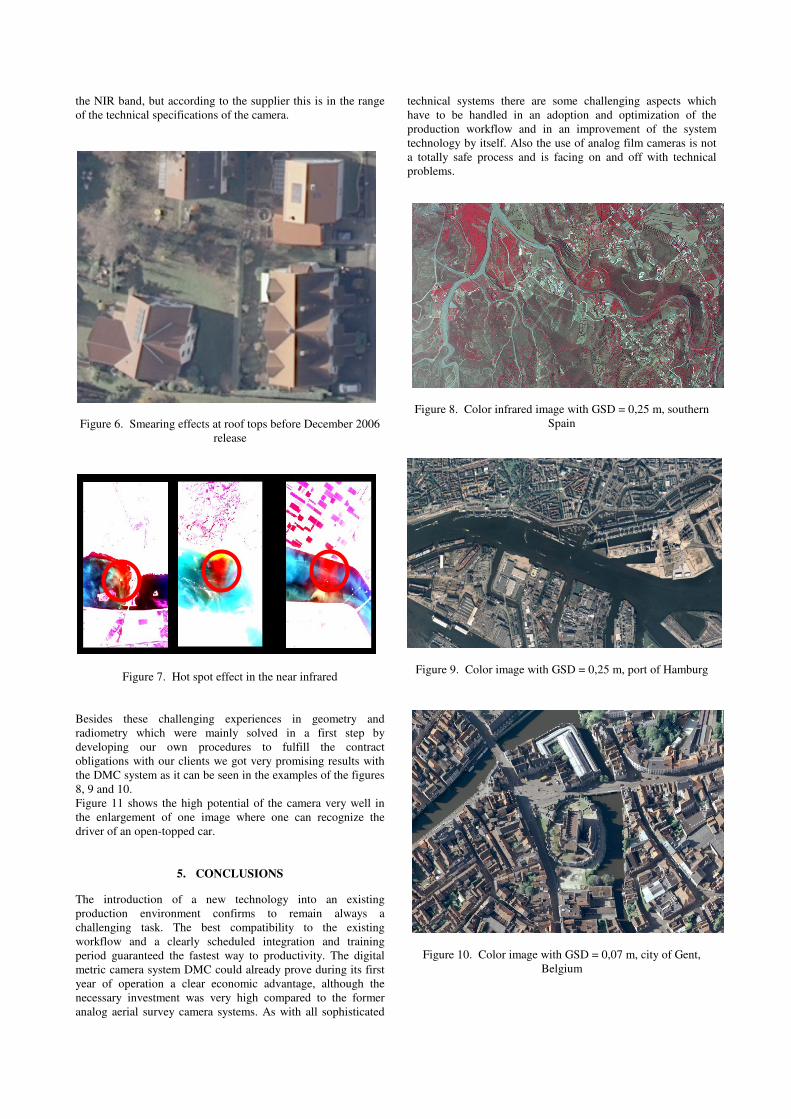
Besides these challenging experiences in geometry and
radiometry which were mainly solved in a first step by
developing our own procedures to fulfill the contract
obligations with our clients we got very promising results with
the DMC system as it can be seen in the examples of the figures
8, 9 and 10.
Figure 11 shows the high potential of the camera very well in
the enlargement of one image where one can recognize the
driver of an open-topped car.
5. CONCLUSIONS
The introduction of a new technology into an existing
production environment confirms to remain always a
challenging task. The best compatibility to the existing
workflow and a clearly scheduled integration and training
period guaranteed the fastest way to productivity. The digital
metric camera system DMC could already prove during its first
year of operation a clear economic advantage, although the
necessary investment was very high compared to the former
analog aerial survey camera systems. As with all sophisticated
technical systems there are some challenging aspects which
have to be handled in an adoption and optimization of the
production workflow and in an improvement of the system
technology by itself. Also the use of analog film cameras is not
a totally safe process and is facing on and off with technical
problems.
Figure 8. Color infrared image with GSD = 0,25 m, southern
Spain
Figure 9. Color image with GSD = 0,25 m, port of Hamburg
Figure 10. Color image with GSD = 0,07 m, city of Gent,
Belgium

The market demands for digital large format cameras are
growing. Further, the images of an aerial survey flight come
more and more in the front as simple rectified images, ortho
images or ortho mosaics. Demand for stereo restitution for
mapping purposes clearly appears to decrease. Thus the
radiometric image quality is more important than before. Many
of the digital camera systems are designed for 12 or more bits
per pixel and band, but many of the viewing systems are not yet
prepared for this. As well the amount of data to be handled is
often underestimated. To get the most benefit out of the new
technology this demands for a close co-operation between the
system suppliers, the service providers and the users.
Figure 11. Enlargement of color image with GSD = 0,06 m
(original at the upper left corner)
6. REFERENCES
Alamús, R. et al., 2005. Validation Process of the ICC Digital
Camera. ISPRS Hannover Workshop “High-Resolution Earth
Imaging for Geospatial Information”, Hannover, Germany
Alamús, R., Kornus, W. and Talaya, J., 2006. Studies on DMC
Geometry. ISPRS Journal of Photogrammetry &Remote
Sensing, 60, pp. 375-386
Dörstel, C., 2003. DMC – Practical Experiences and
Photogrammetric System Performance. In Fritsch, D. and
Spiller, R. (Eds.), Photogrammetric Week 2003, Wichmann,
Heidelberg, Germany, pp. 59-65
Dörstel, C., Jacobsen, K. and Stallmann, D., 2003. DMC –
photogrammetric accuracy – calibration aspects and
generation of synthetic DMC images. In Grün, A. and Kahmen,
H. (Eds.), Optical 3-D Measurement Techniques VI, Vol. I,
Institute for Geodesy and Photogrammetry, ETH Zurich,
Switzerland, pp. 74-82
Dörstel, C., Traub, S. and Wuescher, D., 2005. Towards fully
automated processing of DMC images. ISPRS Hannover
Workshop “High- Resolution Earth Imaging for Geospatial
Information”, Hannover, Germany
Grün, A., 1978. Experiences with Self-Calibrating Bundle
Adjustment. Proceedings of ACSM-ASP Convention,
Washington D.C., USA
Hinz, A., Dörstel, C. and Heier, H., 2001. DMC – The Digital
Sensor Technology of Z/I Imaging. In Fritsch, D. and Spiller, R.
(Eds.), Photogrammetric Week 2001, Wichmann, Heidelberg,
Germany, pp. 93-103
Jacobsen, K., 2006a. EuroSDR Digital Camera Test –
Investigation of DMC block Frederickstad. Internal report, not
published
Jacobsen, K., 2006b. Geometrische Analyse der Intergraph
DMC. Internal report, not published
Jacobsen, K., 2007. Geometry of Digital Frame Cameras.
ASPRS 2007 Annual Conference, Tampa, USA
Madani, M., Dörstel, C., Heipke, C. and Jacobsen, K., 2004.
DMC Practical Experience and Accuracy Assessment.
International Archives of Photogrammetry and Remote Sensing,
Istanbul, Turkey, Vol. XXXIV, Comm. II
Mayr, W., 2004. Bericht über großformatige digitale
Luftbildkameras. Contract Study of CONPIE GmbH, not
published
Mayr, W. and Ohlhof, T., 2004. Geoinformation via parallel
image engineering and image information mining. Proceedings
of ESA-EUSC conference: Theory and Applications of
Knowledge driven Image Information Mining, with focus on
Earth Observation, Madrid, Spain
Sandau, R. et al., 2000. Design Principles of LH Systems
ADS40 Airborne Digital Sensor. International Archives of
Photogrammetry and Remote Sensing, Amsterdam, The
Netherlands, Vol. XXXIII, Comm. I, pp. 258-265
Schroth, R., 2003. Direct geo-referencing in practical
applications. Proceedings of ISPRS WG1/5 Workshop,
Castelldefels, Spain
Schroth, R., 2007a. First experiences with Z/I Imaging DMC
camera. Proceedings of 7. Geomatic Week, Barcelona, Spain
Schroth, R., 2007b. Large Digital Cameras for Aerial Survey of
Geospatial Information. Proceedings of the FIG Working Week,
Hong Kong SAR
Wehrli, H. et al., 2004. Introduction of the 3-DAS-1 Digital
Aerial Scanner. International Archives of Photogrammetry and
Remote Sensing, Istanbul, Turkey, Vol. XXXIV, Comm. I


![Digital Camera Model No. DMC-S3 DMC-S1 · ∗1 DMC-S3 ∗2 DMC-S1 Recording conditions by CIPA standard • CIPA is an abbreviation of [Camera & Imaging Products Association]. •](https://img.dokumen.tips/doc/110x75/5fa82be0b71f0852c4667b2f/digital-camera-model-no-dmc-s3-dmc-s1-a1-dmc-s3-a2-dmc-s1-recording-conditions.jpg)