Embed Size (px)
Citation preview
Graham et. al - Composites Part A Manuscript
1
The development and scalability of a high strength, damage tolerant,
hybrid joining scheme for composite-metal structures
D.P. Graham1/2†, A. Rezai1*, D. Baker1, P.A.Smith2, J.F.Watts2 1 BAE Systems Advanced Technology Centre, PO Box 5, Filton, Bristol, BS34 7QW, UK; 2 Department of Mechanical Engineering Sciences, University of Surrey, Guildford, GU2 7XH, UK; † Now at GKN Aerospace Advanced Technology Centre, PO Box 500, Filton, Bristol, BS34 9AU;
* Corresponding author ([email protected])
A. Hybrid; B. Strength; B. Damage Tolerance; E. Joints/Joining
Abstract
Advanced hybrid joints, which incorporate a specially designed array of macro-scale pins that
provide mechanical interlocking reinforcement, have been developed in order to address the challenges
associated with joining fibre reinforced composites to metals. In the present work, important joint
characteristics including strength, mechanical fatigue, damage tolerance and durability have been studied
and discussed. The results indicate that with advanced hybrid joints it is possible to achieve the benefits
of the respective bonded and bolted systems but with virtually zero net weight gain, or conceivably a
weight reduction as the increased performance of the hybrid scheme could facilitate smaller joints. The
authors also present initial results from a comprehensive manufacturing and scalability trial, and
demonstrate that low-cost, large-scale manufacture of hybrid joints is now feasible.
1 Introduction
Combining dissimilar materials such as fibre reinforced polymer (FRP) composites and metals in
structural applications can facilitate lower mass structures and enhance design freedom. However,
forming robust joints between these materials can be challenging, particularly for safety critical structures
and for systems subjected to challenging conditions, such as blast loading. The mechanical fastening of
composites introduces two key problems. Firstly, preparing such joints usually involves machining or
drilling which can introduce damage in the composite material, and secondly, stress is concentrated at the
discrete loading points associated with the fixing locations. Both factors contribute to premature failure of
the composite by tensile fracture, shear out, cleavage, bearing or pull-through failure modes as described
by Camanho and Matthews [1]. Elongation of holes during fatigue can also constitute problems. Adhesive
bonding is a common alternative and is now applied widely in industry for joining composites. However,
adhesive bonding is very sensitive to surface preparation, and may require expensive pre-treatments and
quality control procedures. Adhesives also degrade over time, especially in hot/wet environments, and
further, high strength adhesives tend to fail in a sudden brittle/catastrophic manner. Inspection of adhesive
joints during service can also be difficult.

Graham et. al - Composites Part A Manuscript
2
Hybrid joints combine mechanical interlocking with adhesive bonding, and have been studied in
order to identify whether the benefits of the respective approaches to joining may be obtained with fewer
shortcomings. A basic form of hybrid joint may be created by combining bonding and bolting to fix two
components together. This type of joint has been studied by a number of authors [2-5]. A much lesser
studied variant is the advanced hybrid joint, which uses a specially designed array of macro-scale pin
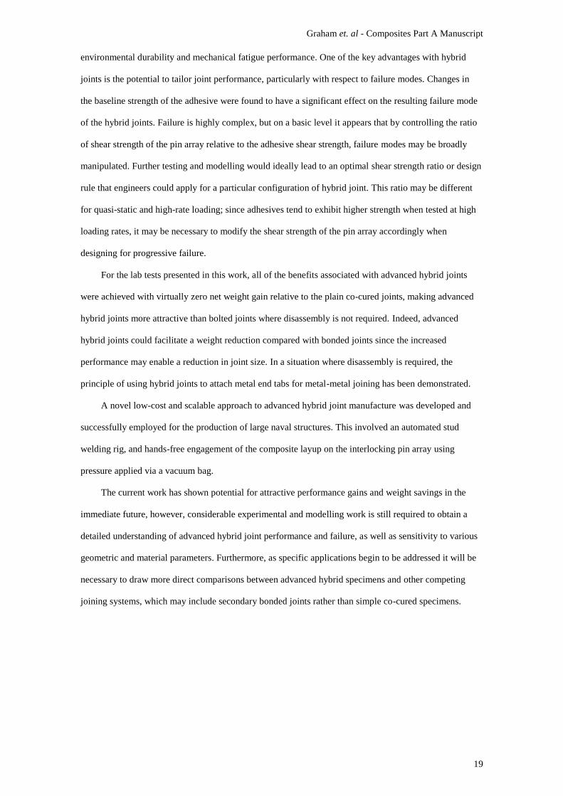
features to provide mechanical interlocking instead of bolts (Figure 1).
Figure 1
The potential uses for hybrid joints are wide-ranging and include applications in aerospace, defence,
automotive, marine and civil engineering sectors, where the use of composite materials continues to grow.
A typical example is the joining of composite topside (above deck) structures to the hull of a large marine
vessel. Using composite materials for topside structures can reduce overall mass and also lower the centre
of mass of a vessel. While total mass affects the speed, acceleration and fuel economy of ships, the centre
of mass can have a profound effect on stability and manoeuvrability. In a military sense, using composites
also adds the potential for enhanced stealth capability and multifunctionality. One of the main obstacles to
greater integration of composites in large ships is the lack of a robust and damage-tolerant joining scheme
for composite-metal interfaces. The U.S. Navy Zumwalt Class Destroyer has a composite deckhouse
which is bolted to metal end tabs and then welded to the hull [6], which may imply that lightweight
adhesive bonding solutions were considered unsuitable for this particular structural application.
A second major obstacle is manufacturing cost. Typical costs for the construction of a composite
helicopter hangar were estimated to be around 50% higher than for the equivalent steel structure. Despite
this, overall through-life costs are thought to be around the same as for the steel equivalent owing to the
high cost of corrosion protection/maintenance associated with metallic structures [7]. Nevertheless, it is
clear that while efforts are being made to reduce costs in processing large composite panels, such as with
modern pultrusion technologies [8], it is imperative that any potential joining solution is also
demonstrated as being low cost and easily scalable.
The purpose of this work was to evaluate whether hybrid joints could be used to address some of the
difficulties in joining composites to metals in defence and aerospace applications. Multiple variants of
hybrid joint were developed and joint characteristics including strength, mechanical fatigue, damage
tolerance and durability are discussed. Following the initial work, a case study for a maritime application
was conducted to explore further the manufacture and scalability of hybrid joints. The aim here was to
investigate whether any performance advantages associated with hybrid joints could be feasibly
transferred to industry, or whether the cost and difficulty of processing was prohibitive. The next section
Graham et. al - Composites Part A Manuscript
3
provides a brief review of some significant hybrid joining studies reported in the literature, including
traditional bonded/bolted and contemporary advanced hybrid joining approaches.
2 A brief review of hybrid joint technology
2.1 Bonded/bolted hybrid joints
It has been suggested that combining bolting and bonding techniques for aerospace applications is
often regarded unnecessary since the adhesive is typically much stiffer than the fasteners and therefore
transfers the majority of the load [2, 3]. In terms of material properties, the opposite is in fact true. Even
with a relatively stiff epoxy-based adhesive, mechanical fasteners (typically made from steel or titanium)
generally have much higher shear and tensile elastic moduli. However, it is acknowledged that adhesive
joints often exhibit a stiffer response compared with similar bolted joints, and this stems from geometrical
factors. In the case of a single-lap adhesive joint with non-rigid adherends it is widely appreciated that
transverse and normal strain in the adhesive bond will generally be much greater near the overlap ends
than in the central joint region. This is a result of differential straining of the adherends and joint rotation.
The region in the middle of the joint, away from the free edges, experiences considerably lower strain and
consequentially less stress. Thus, adding a mechanical fixing in the middle of the joint will do little to
improve joint performance prior to the initiation of damage in the adhesive bond. It is understandable then
how mechanical fixings in hybrid joints have been shown to have poor load transfer, although it could be
argued that the region of adhesive in the middle of a plain bonded lap joint is equally underutilised. For
this reason, it has been suggested that relatively compliant adhesives should be used in hybrid joints to
improve load sharing with the fasteners [3, 9], but often the desire of the end-user is to improve the
properties of an adhesive joint, not to ‘get a hybrid joint to work’ by compromising the adhesive, or
merely create a sealed, fastened joint.
If indeed the mechanical reinforcement remains redundant until damage to the adhesive occurs, this
implies that there would be no increase in elastic loading limit for a hybrid joint compared with a standard
adhesive joint. This may not be entirely representative for systems involving reinforcement in the more
highly strained region of the bond, and also neglects potential for the retaining features of the mechanical
fasteners to inhibit mode-I dominated failure by reducing peel stresses, which act to separate the
adherends at each end of the overlap region. Another factor contributing to the inefficiency of bolts in
hybrid systems relates to bolt-hole clearances. It is necessary to make a distinction between hybrid joints
that have had clearance holes drilled to allow mechanical fixing, and joints that have been fastened and
then co-cured with the composite adherend during composite processing. For multi-fastener joints with
clearance holes, it is generally accepted that some level of adherend yielding must take place to facilitate
shear loading through all of the fasteners [10]. Co-curing the fasteners minimises damage to the

Graham et. al - Composites Part A Manuscript
4
composite, and may also enhance shear load transfer through the fasteners as a result of the intimate
contact between the fasteners and composite adherend.
Matsuzaki et al. [11] studied composite-metal joints that had been fastened with multiple fixings and
then co-cured. It was found that shear strength was almost double for hybrid joints compared with plain
co-cured joints, which was attributed to the presence of the bolts since the strength was similar for the
bolted control joints. Load-displacement curves showed that hybrid joints had higher stiffness than the
bolted joints, which was attributed to the adhesive as this was similar for the adhesive control joints.
However, it was noted that the hybrid joints exhibited this high stiffness beyond the stress at which the
adhesive joints failed. It is thought that this was not an extension of elastic behaviour, as there was some
evidence that crack initiation in the adhesive occurred at similar stresses in both the hybrid and bonded
control joints. Instead, it is thought that this was related to the influence of the bolts in inhibiting crack
propagation; indeed, it was noted that advancing cracks in the bond line arrested at the fasteners.
Nevertheless, it was apparent that hybrid joints could offer high stiffness joints, with a high ultimate
strength and progressive ductile failure, which is not easily achievable with the respective bonding or
mechanical fastening techniques. The main disadvantages with this particular hybrid technique were the
additional weight associated with the fixings, and complexity of the manufacturing process.
2.2 Advanced hybrid joints
Early work by Kellar and Smith [12] demonstrated that advanced (pinned) hybrid joints could have
greater strength than equivalent bonded joints, and much greater mechanical energy absorption during
failure as a result of non-catastrophic failure modes. The mechanical properties of this type of joint are
heavily dependent on the method of attaching/creating pins on the metal component, and the interaction
of these pins with the composite component. A number of techniques have been used to produce pins on
the surface of a metallic component for the purpose of hybrid joining – these can be broadly categorised
as surface restructuring [12] or additive layer processes [13, 14].
Surface restructuring involves redistributing the material on a component surface to create raised
and lowered regions. The main drawbacks to this approach are limited control of pin geometry, excessive
damage to the surface caused by the restructuring process, and the large costs associated with using an
electron beam to ‘drive’ material across the surface. Despite this, it has still been identified as having
potential for use on large marine structures [15]
Additive layer manufacture (ALM) techniques have been widely used in research on advanced
hybrid joints. ALM techniques vary considerably but the principle is the same, to ‘build up’ features by
sequentially adding layers of material to a substrate. Techniques based on metal-powder processing [13]
allow reasonable control of pin geometry and do not generally cause excessive damage to the existing

Graham et. al - Composites Part A Manuscript
5
surface. Two common types of metal powder processing are selective laser melting (SLM) and laser
metal deposition (LMD). SLM utilises a metal powder bed, over which a laser spot is focused to
selectively melt layers of material. LMD works by blowing metal powder into the focal point of a high
power laser. For research purposes these techniques are in many respects ideal, but they remain a costly
option for industry. Cold metal transfer (CMT) is a relatively modern technique that allows droplets of
molten metal wire to be deposited onto a substrate in progressive layers. Ucsnik et al. [14] used an
adapted CMT technique, which welded the end of the feed wire to a substrate, and then combined
resistive heating with tensile force to fracture the wire. This left a short pin on the surface. This adapted
additive layer technique effectively deposits the full length of the pin in a single action, and subsequently
forms the head geometry as part of the break-off process. It is generally possible to perform each of these
processes on a range of metals including steel, aluminium and titanium.
Once an array of pins has been prepared, it is necessary to integrate this with the composite material.
Typically, manufacturing advanced hybrid joints achieves adhesive bonding as part of the composite
processing, such that the array of pins is co-cured with the composite. This begins with engaging the array
of pins in a pre-preg or dry fibre preform, and then curing, or infusing and curing, respectively. The next
section provides details on the manufacturing techniques and specimen configurations employed within
this study.
3 Joint Manufacture
3.1 Introduction
This section provides an overview of the range of joint geometries employed in this work, and the
associated manufacturing methods. Table 1 and Table 2 list specimens used for coupon testing, and
manufacturing information specific to each type. Joint information has been categorised according to the
study type. Since no other type of hybrid joint was studied in this work, the term ‘hybrid joint’ is used
hereafter to refer to the advanced (pinned) hybrid joints being discussed. The pin material was the same
as the metallic adherend unless otherwise stated. The quoted ‘array type’ denotes the number of pins in
each row moving progressively from the composite adherend side of the lap joint to the metal adherend
side. The array was offset from each edge of the overlap by approximately 2 mm in the case of 25 mm x
25 mm joints, and 4 mm in the case of 50 mm x 50 mm joints. Within the array, pins were evenly spaced
according to the number of pins in each row. The term ‘control’ is always used to refer to the respective
plain co-cured equivalent of the hybrid joint being discussed in each section. The control joints were
therefore nominally identical to their hybrid counterparts, but without the pin reinforcement. This allowed
meaningful comparisons to be drawn, where the specific effect of the pin reinforcement could be
identified without being concerned about other differences that might occur as part of a secondary

Graham et. al - Composites Part A Manuscript
6
bonding process, for example. Further general information regarding manufacture of the metal adherends
and composite processing is given in the sub-sections that follow.
Table 1
Table 2
3.2 The Interlocking Pin Array
A number of techniques were evaluated for manufacture of the interlocking pin arrays. A proprietary
LMD technique was developed using a high-power laser and blown-metal-powder-feed system. With this
process it was possible to produce a wide variety of pin sizes and shapes including pointed and bulbous
tipped pins. A three-axis stage system and CNC controller were used to enable automated production of
consistent arrays of pins. The process time was around 10 sec per pin. All LMD specimens were
manufactured with stainless steel (AISI 316) pins on 3 mm thick stainless steel (AISI 316L) substrates. A
pure argon shielding gas was used during the manufacture of these specimens.
A CMT system was adapted for deposition of pins in a similar way to the method described by
Ucsnik et al. [14]. Metal adherends were manufactured in mild steel (ABS DH36), aluminium (AA7050)
and titanium (6Al-4V). Mild steel was selected with a maritime application in mind, while the aluminium
and titanium variants were made to explore opportunities within the aerospace industry. Pure argon was
used as a shielding gas for the mild steel and aluminium substrates. Obtaining high quality titanium welds
is notoriously challenging, and was the case in this work. The quality of titanium welds was improved
using a 62.5% Argon/35% Helium/2.5% CO2 shielding gas mix (Inomaxx Plus, Air Products), along with
thorough abrasion and acetone cleaning of the substrate beforehand. Despite this, the welds were still
considerably more brittle than for aluminium and steel variants. Varying the electrical input, tensile
break-off force and shielding gas all had an influence on the pin geometry, and while it was possible to
produce different geometries such as sharp or bulbous tipped pins, controlling specific dimensions of the
pins was found to be quite difficult.
In addition to the above ALM methods, stud welding techniques were investigated as a fast, low-
cost method for scaled-up production. Stud welding is a well-established scalable process, first applied
for large-scale production in HM Dockyard Portsmouth in 1918 [16]. The short process time of stud
welding techniques results in a small heat affected zone (HAZ), making it ideal for welding small pins to
thin plates. Stud sizes typically range from 6 mm to 30 mm in diameter, with the smallest commercially
available being around 3 mm. However, recent advances in welding pack equipment have enabled more
precise control of welding parameters, which has made it possible to conduct experiments welding
smaller diameter pins. More specifically, two types of stud welding process were used, capacitor
discharge stud welding (CDSW) and drawn-arc stud welding (DASW). It was found that the high-energy,
exceptionally short duration process (a few milliseconds) of CDSW produced more consistent results for
Graham et. al - Composites Part A Manuscript
7
welding pins of less than 2 mm diameter, whereas DASW produced more consistent results for pins larger
than 2 mm. For general test specimens, 1 mm and 1.5 mm cylindrical pins were welded using CDSW.
The height of the pins for all test specimens was typically 2 mm - 5 mm, depending on the selected
composite layup. Nominally pins protruded at least 80% through the laminate thickness in each case. The
only exceptions to this specification were the high rate specimens, which were the subject of an
inadvertent manufacturing fault resulting in slightly shorter pins. As such, the tops of the pins in the high-
rate specimens terminated roughly 50% through the laminate thickness on average. All pins were attached
normal to the metal adherend surface.
With regards to the geometry of the pin arrays, a preliminary sensitivity study was conducted using
double lap joints with square 8 x 8 pin arrays manufactured using LMD (referred to as P1 specimens).
Following the preliminary findings (discussed more thoroughly in section 5.2), the majority of subsequent
hybrid joints were manufactured with 3 pins on the first row (nearest the composite adherend), 4 pins on
the second row, and 6 pins on each of the remaining four rows.
3.3 Composite Processing and Joining
The pinned substrates were grit-blasted with grade-60 grit, rinsed with water and promptly
degreased in acetone. Two composite processing methods were used a) vacuum assisted resin transfer
moulding (VARTM), and b) pre-preg.
For specimens manufactured by VARTM, glass-fibre plies (specific to each joint type, as indicated
in Table 1 and Table 2) were individually laid up onto the array of pins. The pin spacing generally
allowed favourable location at gaps in the weave architecture so as to minimise fibre damage and
disruption. Tweezers were used to guide the fabric over the pins until the pins had been covered;
remaining plies were then placed on top. For specimens with an epoxy matrix, a quantity of LY564
(Huntsman) epoxy resin was degassed in a vacuum oven at 60 °C for 30 minutes. This was left to cool to
40 °C before adding 35%wt. of Aradur 2954 (Huntsman) curing agent. The two-part mix was stirred and
placed under vacuum at 30 °C for a further 20 minutes before infusing. A heat mat was used to cure the
joints. Temperature was maintained at approximately 60 °C for 2 hours, while consolidation pressure was
provided by the vacuum bag. Single and double lap joint specimens were manufactured in this way. For
specimens with a vinyl-ester matrix, the joints were infused within 5 minutes of mixing the Dion 9500-
501 resin (Reichhold) and Trigonox 42PR catalyst (AkzoNobel), no degas was performed. Joints were
left to cure at room temperature and remained un-tested for a period of 1 week. Plain co-cured (control)
joints were prepared in the same manner, co-curing the fabric against flat metal adherends.
For specimens manufactured using pre-preg, 8552 IM7 (Hexcel) UD carbon fibre pre-preg was
used. The pre-preg was laid up in the following symmetrical cross-ply configuration:
Graham et. al - Composites Part A Manuscript
8
[(0/90)7/0̅]𝑠
A 25 gsm glass fibre veil was included at the metallic interface of the pre-preg joints in order to
graduate the coefficient of thermal expansion (CTE) between the metallic and carbon fibre reinforced
polymer (CFRP) adherends. A CTE mismatch is known to be very problematic for bonded lap joints
where the adhesive undergoes high temperature cure, and especially where the CTE mismatch is large
such as with aluminium-CFRP joints [17]. Large variations in operational temperature also present a
problem for joints with a high CTE mismatch. A preliminary sensitivity study revealed that using a veil
was effective at reducing residual stress, whereas applying no mitigation scheme resulted in joints with
exceptionally low lap-shear strength. Using a veil was not deemed as necessary for the steel to glass fibre
reinforced polymer (GFRP) joints since the difference in CTE is much less and the cure temperature was
much lower. The thickness of the aluminium and titanium substrates had been specified to match the
longitudinal stiffness of the carbon fibre laminate. Specimens were cured in an autoclave in accordance
with the pre-preg material cure schedule. In all cases, the weight difference between hybrid and control
specimens was negligible. For the purpose of this study, galvanic corrosion issues relating to the use of
aluminium and carbon fibre were not considered. Mitigation schemes are currently under development so
assessing the mechanical properties of these joints was still of value.
4 Test Methods
4.1 Quasi-Static Testing
The strength and failure mode of the joints was assessed using an Instron 4507 universal testing
machine. Tests were performed at quasi-static rates, with a crosshead displacement of 0.5 mm/min. Grip
motion was nominally aligned in the joint plane so as to result in predominantly mode-II loading.
Strength was evaluated in terms of peak engineering shear stress.
4.2 High-Rate Tests
It is known that the performance of adhesive joints can vary with strain-rate [18]. It was therefore of
interest to examine hybrid joints under such conditions. In the present work, tests were conducted using a
bespoke hydraulic testing machine (Phoenix Calibration) capable of input velocities up to 20 m s-1 and a
maximum load of 50 kN. Instrumentation included a strain gauge on either side of the metallic adherend,
close to the joint region, a piezoelectric load cell designed for dynamic loading conditions, and high speed
cameras. High speed cameras were required for visual examination of failure modes, but were also used
in conjunction with digital image correlation (DIC) software to collect relative displacement data.
Furthermore, a 100 mm lost-motion device was included in the load train in order to allow the hydraulic
rig to accelerate to the desired input velocity prior to loading the specimen. After the initial free travel, the
link behaved like a rigid body, thus transmitting the force of the hydraulic ram to the specimen.
Graham et. al - Composites Part A Manuscript
9
The actuator displacement rates were between 7.5 m s-1 and 9.5 m s-1 and the corresponding loading
rates for the elastic strain region were estimated to be between 100 N/µs and 130 N/µs. Data from strain
gauges placed on the steel adherend, adjacent to the joint region, were generally in good agreement with
those obtained from the Kistler load cell situated within the load train. However, strain gauge data for a
few specimens exhibited abnormally high peaks, which were not simply explained and may have been
related to faulty strain gauges or erroneous setup. Since the Kistler data was most consistent, and
corroborated by the strain gauges, these values are used within the current analysis. A 30 kHz filter was
applied to the high-rate curves to improve clarity.
4.3 Drop-Weight Testing
High strength adhesives tend to have poor damage tolerance characteristics associated with the
brittle nature of their failure. Damage tolerance was evaluated by measuring residual strength after
subjecting the joints to impact loading. An instrumented drop-weight testing rig was used to apply the
impact loads. This method was highly repeatable, and allowed precise control of the damage location.
Joints were subjected to impacts in the range 7 – 15 J, imparted on the composite face of the overlap
using a 20 mm diameter hemispherical tup. Figure 2 illustrates this test configuration. The intention was
to aim for a worst-case scenario and hence the impact site was offset slightly toward the composite
adherend side of the overlap region rather than being in the centre. Here, the stress field was likely to be
most conducive to damage propagation during loading as a result of the large stiffness mismatch.
Furthermore, it seems plausible that the reduced pin reinforcement at this edge would result in visible
damage at lower impact energies.
Figure 2
4.4 Environmental Conditioning
Hot-wet environmental conditioning is known to influence and in general degrade the performance
of composite materials and adhesive bonds. A reduction in stiffness and strength can usually be linked to
moisture absorption after sustained exposure to this type of environment [19]. For structural or other
potentially critical multi-material joints, it is therefore necessary to evaluate performance under these
conditions. An environmental chamber was used to conduct ‘accelerated ageing’ of stainless steel-glass
fiber joints.
Specimens were left inside an environmental chamber for around 3000 hours at 50 °C and 85%
relative humidity. Since a low temperature cure was used during manufacture, the joints were not
subjected to temperatures higher than 50 °C. To do so might result in post-curing of the resin, thus
modifying the mechanical properties and voiding any comparison with control specimens.
Graham et. al - Composites Part A Manuscript
10
4.5 Fatigue Testing
It has been suggested that hybrid joints can exhibit superior fatigue performance compared with
plain adhesive joints [11, 20]. A preliminary evaluation of joint performance under cyclic loading was
carried out using an Instron 8502 hydraulic mechanical testing machine. Tests were performed under load
control, such that the machine compensated for the increasing specimen compliance resulting from crack
growth. Loading was tension-tension, with a peak load of 0.5σu, where σu was the ultimate joint strength
determined from quasi-static tensile testing. A stress ratio of 0.1 and cycle frequency of 3 Hz was used.
5 Results and Discussion
5.1 Introduction
Table 3 provides a summary of control and hybrid specimen joint strengths for the configurations
tested in this work. The following sections include stress-displacement curves and a more comprehensive
discussion of the data.
Table 3
5.2 Quasi-Static Testing
Preliminary tensile lap-shear tests of P1 double-lap hybrid joints showed an improvement of up to
60% in strength compared to standard co-cured control specimens, which was proportionally consistent
with improvements observed by Kellar and Smith [12]. However, failure was in the composite adherend
at the joint overlap edge and occurred at much lower stress than would be expected for the composite. It
was thought that the large stiffness mismatch between the reinforced joint region and composite adherend
had caused severe stress concentration at the edge of the overlap, and that fibre disruption resulting from
the dense pin array also contributed to the problem. To alleviate these issues, a modified pin array scheme
was adopted for subsequent joints as described in section 3.2. The modified pin configurations used less
pins toward the adherend overlap edges according to where the greatest stiffness mismatch was expected.
These configurations are yet to be optimised, but showed an immediate influence on failure mode.
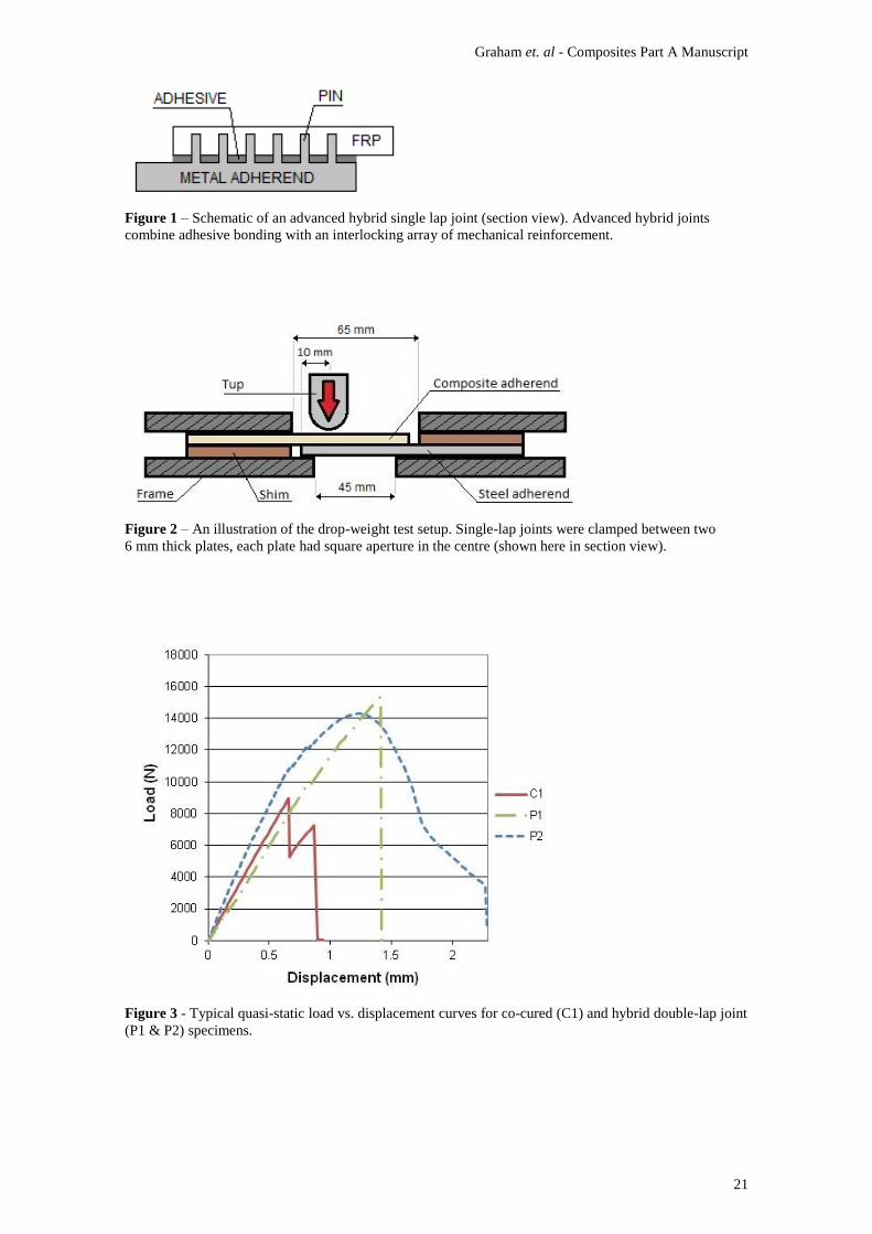
Typical load-displacement curves for P1 hybrid, P2 hybrid and control joints are shown in Figure 3.
The change in the hybrid joint pin array geometry led to slightly reduced ultimate strength for P2
specimens, but the failure mode changed from off-joint fibre fracture to a more ductile mode developing
from within the joint region. Combined with the high strength of hybrid joints, the more ductile behaviour
led to greatly enhanced energy absorption during failure, as evidenced by the increased area under the
load-displacement curve. Following an initial elastic response, failure mechanisms were broadly observed
in three stages:
I. Crack initiation in the primary bondline – usually at the metal adherend runout but sometimes at
the composite adherend runout as well.
Graham et. al - Composites Part A Manuscript
11
II. Crack growth through the primary bondline – in a progressive manner, occasionally the crack
arrested at a row of pins for a time.
III. Pin related mechanisms – including bearing failure/ploughing in the composite, pin yielding, pin
pullout and shear failure of the pins.
While I, II and III are stated as generally occurring in series, it is likely that the mechanisms
associated with stage III were also active during stage II, but to a lesser extent. It was also noted that P2
joints generally had a stiffer initial loading response, and this was thought to be related to inhibition of
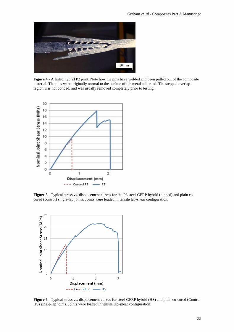
sub-critical damage in the early stages of loading. Figure 4 shows one of these joints post-failure.
Figure 3
Figure 4
Tests on P3 single lap joint specimens showed average increases in strength and energy absorption
(estimated from the area under load-displacement curves) of around 70% and 400%, respectively,
compared with control specimens. Figure 5 shows typical stress-displacement curves for hybrid single lap
joints and control specimens. For this configuration, the curve exhibited a double-peak response rather
than the bell-like curve seen for the double lap joints, suggesting a more stepwise progression through
stages I – III.
Figure 6 shows typical stress-displacement curves for HS (pinned) and control single-lap joints.
Relative to the control specimens, the ultimate strength and energy absorption (estimated from the area
under load displacement curves) of HS specimens was on average 80% and 1000% greater, respectively.
A combination of very high strain to failure and sustained load bearing capability was observed, and the
vast majority of this gain was a result of prolonged stage III failure, particularly through pin yielding and
pull-out mechanisms. This was possible as a result of the strong, high quality CMT welds at the base of
the pins. Stiffness of the HS joints was initially the same as for control joints but reduced with the
progression of subcritical damage. Damage initiated at a lower load in the HS joints and is characterised
by the notches and other nonlinearities in the stress-displacement curve. It is thought that optimisation of
the pin array and manufacturing process could reduce stress concentration within the joint region and
increase the damage onset threshold.
Figure 5
Figure 6
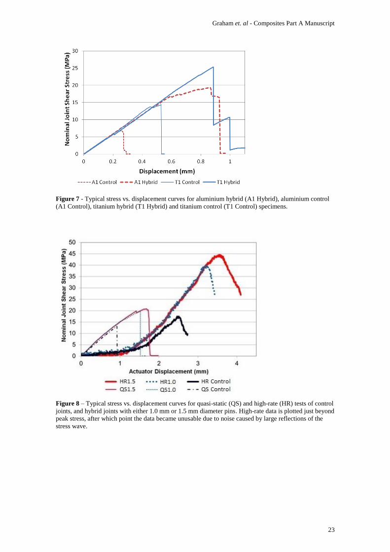
Figure 7 shows typical stress-displacement curves for the aluminium-CFRP and titanium-CFRP
hybrid and control joints. The aluminium hybrid joints showed 157% and 900% improvements in ultimate
strength and energy absorption, respectively, relative to control specimens. Failure was progressive, but
not to the extent of that seen in the steel-GFRP joints. Part of this was likely due to the reduced quality
and strength of the aluminium CMT welds, such that the pins had a greater propensity to shear at the base

Graham et. al - Composites Part A Manuscript
12
rather than undergoing significant yielding and pull-out. It is important to note that the improvements
associated with the aluminium-CFRP joints appear magnified due to the very low strength control
specimens that were heavily compromised by the CTE mismatch. The difference in performance may not
be as pronounced for other aluminium-CFRP configurations that incorporate a thicker veil, different
layup or a thicker bondline. For this case at least, linear elastic loading of the hybrid joints generally
appeared to continue beyond the point at which the control specimens had failed, indicating that the
incorporation of the pin array had increased the damage onset threshold. This was unusual, Parkes et al.
[13] had observed a similar increase in the elastic limit of hybrid joints relative to control specimens;
however, other data presented in the current work tended to show subcritical damage to the primary bond
line of a hybrid joint at about the same load as the respective control specimens failed. While it is possible
that the increase of the elastic limit was caused by a favourable pin/stress-field interaction that reduced
stress intensity near the overlap ends, the context of a large mismatch in CTE cannot be ignored. It is
therefore suggested that the reinforcement may have counteracted some of the residual stress effects
associated with a CTE mismatch. Three hypotheses are put forward:
1. Fibre disruption in the hybrid joints effectively increased the CTE of the laminate in the joint
region and thus the resin properties became more dominant, reducing the residual stresses
due to CTE mismatch.
2. Contraction of the aluminium substrate during cooling (after the high temperature curing
process) was resisted by the pins embedded in the laminate, thus transferring a portion of the
residual stress into the pins and reducing the burden on the adhesive.
3. Axial contraction of the cylindrical pins on cooling after the high temperature curing process
induced a small amount of through-thickness compression of the primary bond line.
Further experimentation/modelling work is required to test these hypotheses and evaluate the extent
to which these effects may influence the performance of joints between adherends with significantly
different CTE.
The titanium joints showed 67% and 191% improvements in ultimate strength and energy
absorption, respectively, relative to control specimens. Failure appeared to be on the cusp between brittle-
catastrophic and ductile-progressive regimes, but involved minimal pin yielding and pull-out. Initially, a
crack opened at the metal adherend runout, propagating approximately one quarter of the primary
bondline length. Cracks then began to open in the interlaminar regions of the composite, in the area
around the metal runout. Ultimate failure occurred by fibre fracture at the metal runout. It is thought that
this failure was driven by manufacturing defects caused by the presence of the pins, which include fibre
Graham et. al - Composites Part A Manuscript
13
waviness, resin rich regions and voids. There is certainly scope for greater improvements in performance
with further development of the manufacturing process and joint configuration.
Figure 7
5.3 High-Rate Tests
Figure 8 is a plot of engineering shear stress against actuator displacement for quasi-static and high-
rate tests, and shows a typical curve for each type of specimen. Advanced hybrid joints were found to be
stronger than the control specimens in both quasi-static and high-rate tests. Further, as expected, each
respective joint type sustained higher loads when tested at high rate compared with quasi-static tests.
However, the magnitude of the increase for hybrid joints was greater than that seen for the control
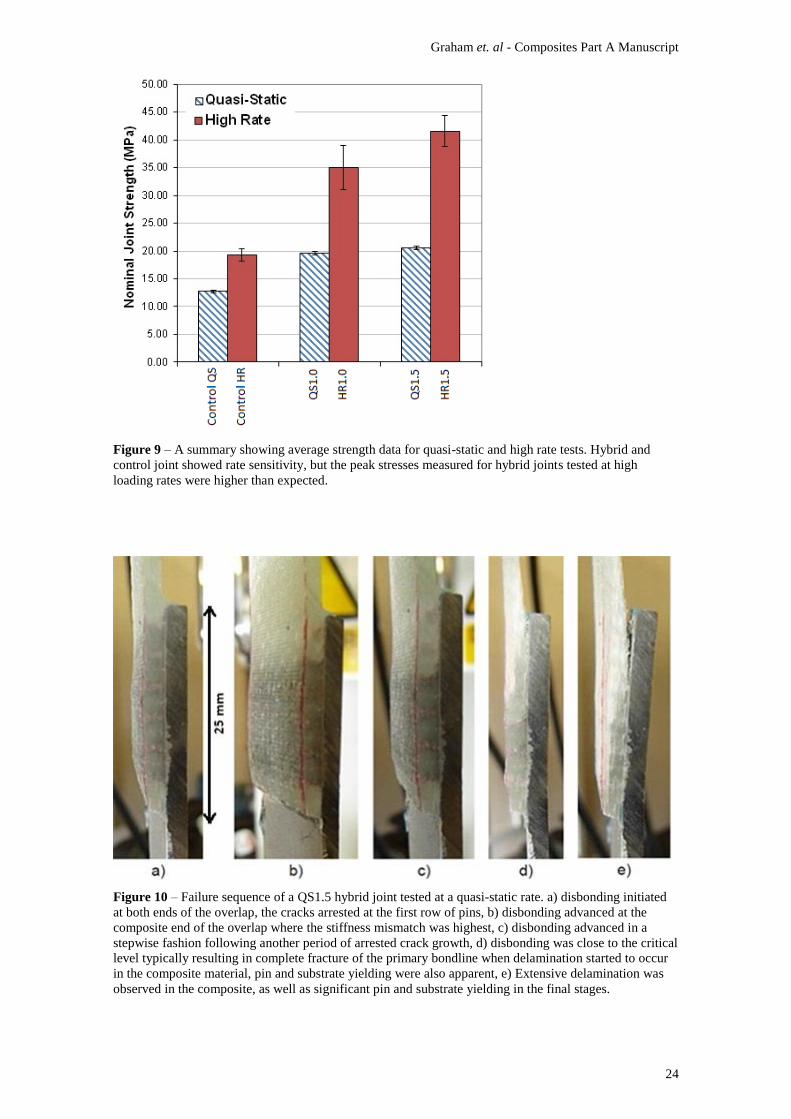
specimens (Figure 9). Plain co-cured control joints exhibited an average peak stress increase of 45%. The
HR1.0 and HR1.5 joints showed an average peak stress increase of 77% and 84%, respectively, compared
with QS1.0 and QS1.5 specimens tested at a quasi-static loading rate. This suggests that the load bearing
capability of hybrid joints was enhanced by some additional means besides the viscoelastic effects
associated with the adhesive. The time period and actuator displacement over which the hybrid joints
sustained load was considerably greater than for the control specimens, again highlighting the progressive
nature of the hybrid joint failure. Failure of the control specimens was brittle-catastrophic, as it was for
control specimens tested at quasi-static rates.
Figure 8
Figure 9
Figure 10 shows the failure sequence of a QS1.5 specimen. Failure comprised fracture of the
primary bondline, pin bending, bearing failure, interlaminar failure of the composite material and plastic
deformation of the steel adherend. Interlaminar failure had not been in observed in the other steel-GFRP
hybrid joint configurations presented in this work. In this case, it is suggested that interlaminar failure
was initiated due to the slightly shorter pins in these joints (as described in section 3.2) behaving as stress
concentrations/damage initiation sites within the laminate. Similar failure characteristics were observed at
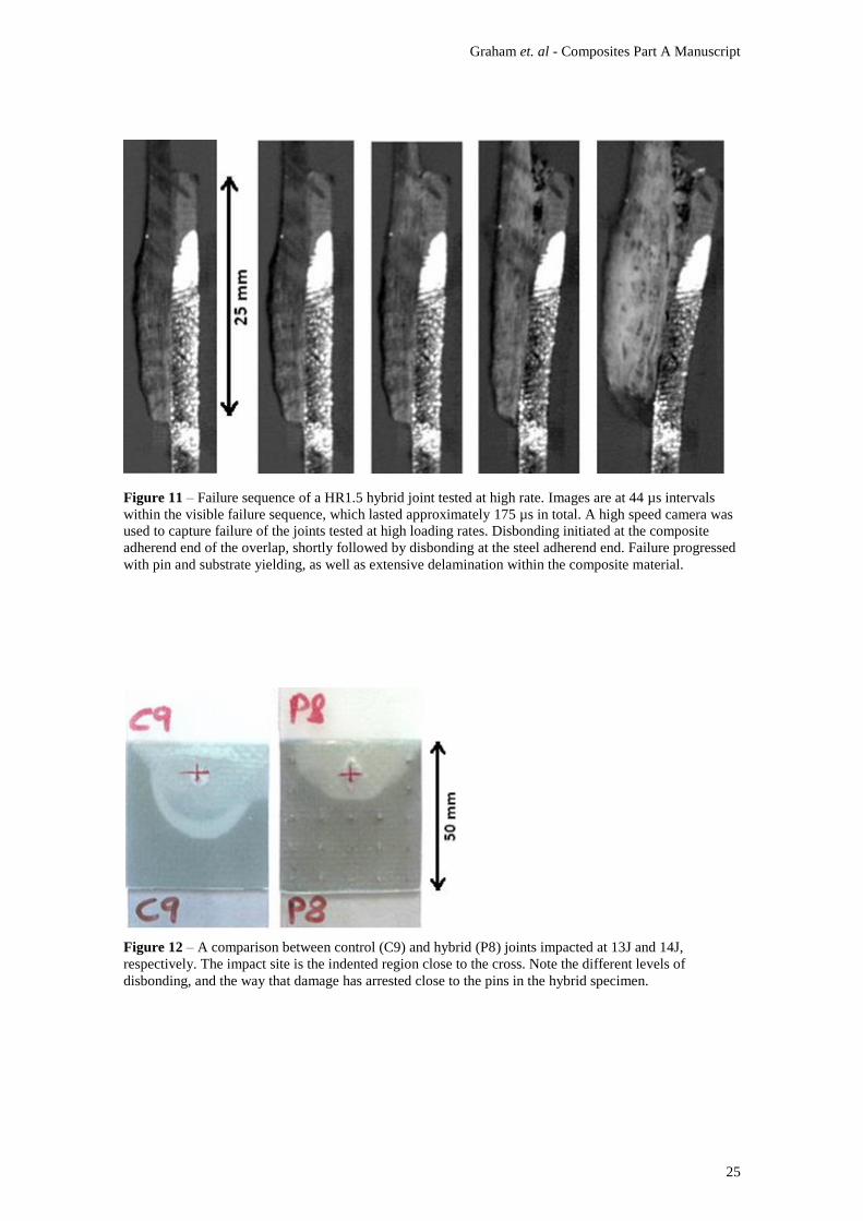
high loading rates, including widespread interlaminar failure. Figure 11 shows images at 44 µs intervals
throughout failure of a typical HR1.5 specimen tested with a high loading rate. High-rate failure modes
were found to be broadly comparable to what was observed at quasi-static rate for this joint configuration.
Pull-out was not thought to play a major role in failure of these particular hybrid joints, for quasi-static or
high loading rates, as a result of the extensive interlaminar failure in the composite.
Figure 10
Figure 11
5.4 Drop-Weight Testing
It was found that an 11 J impact was not sufficient to induce any disbonding or delamination in the
PD (high pin density) specimens - the only sign of damage was slight indentation of the composite where
Graham et. al - Composites Part A Manuscript
14
the tup struck the surface. While this was a useful finding, it did not facilitate an evaluation of damage
progression within the hybrid joints. The PS specimens were manufactured with a lower pin density such
that it was possible to initiate damage throughout the impact energy range tested. The results showed that
damage was initiated in the PS specimens throughout the 7 J – 15 J range. This damage appeared to be
limited to adherend disbonding and slight indentation/crushing at the impacted surface, no delamination
was observed within the composite substrates following impact.
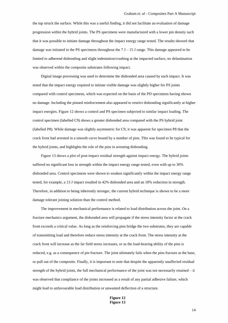
Digital image processing was used to determine the disbonded area caused by each impact. It was
noted that the impact energy required to initiate visible damage was slightly higher for PS joints
compared with control specimens, which was expected on the basis of the PD specimens having shown
no damage. Including the pinned reinforcement also appeared to restrict disbonding significantly at higher
impact energies. Figure 12 shows a control and PS specimen subjected to similar impact loading. The
control specimen (labelled C9) shows a greater disbonded area compared with the PS hybrid joint
(labelled P8). While damage was slightly asymmetric for C9, it was apparent for specimen P8 that the
crack front had arrested in a smooth curve bound by a number of pins. This was found to be typical for
the hybrid joints, and highlights the role of the pins in arresting disbonding.
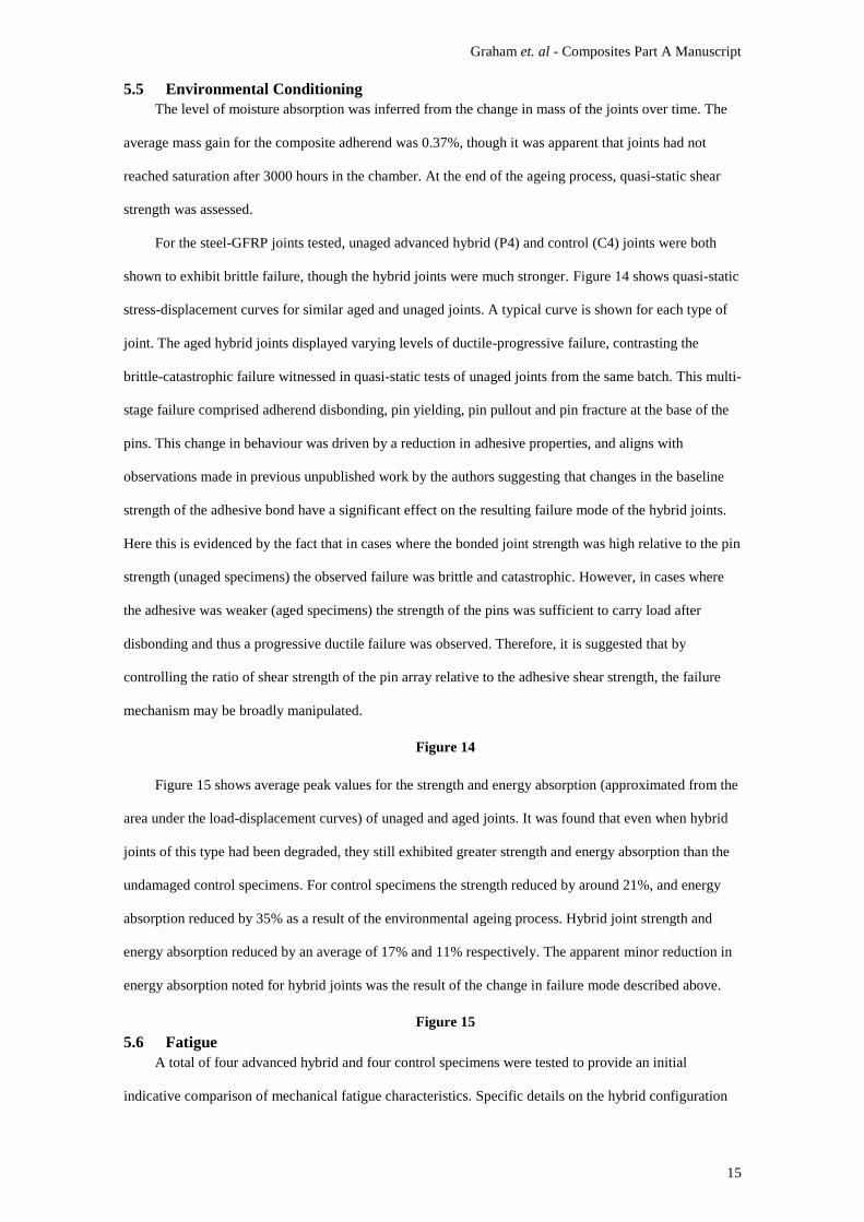
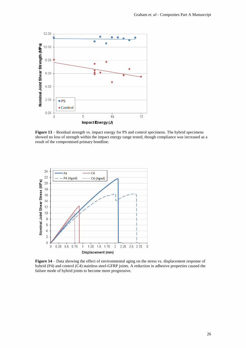
Figure 13 shows a plot of post-impact residual strength against impact energy. The hybrid joints
suffered no significant loss in strength within the impact energy range tested, even with up to 30%
disbonded area. Control specimens were shown to weaken significantly within the impact energy range
tested, for example, a 13 J impact resulted in 42% disbonded area and an 18% reduction in strength.
Therefore, in addition to being inherently stronger, the current hybrid technique is shown to be a more
damage tolerant joining solution than the control method.
The improvement in mechanical performance is related to load distribution across the joint. On a
fracture mechanics argument, the disbonded area will propagate if the stress intensity factor at the crack
front exceeds a critical value. As long as the reinforcing pins bridge the two substrates, they are capable
of transmitting load and therefore reduce stress intensity at the crack front. The stress intensity at the
crack front will increase as the far field stress increases, or as the load-bearing ability of the pins is
reduced, e.g. as a consequence of pin fracture. The joint ultimately fails when the pins fracture at the base,
or pull out of the composite. Finally, it is important to note that despite the apparently unaffected residual
strength of the hybrid joints, the full mechanical performance of the joint was not necessarily retained – it
was observed that compliance of the joints increased as a result of any partial adhesive failure, which
might lead to unfavourable load distribution or unwanted deflection of a structure.
Figure 12
Figure 13
Graham et. al - Composites Part A Manuscript
15
5.5 Environmental Conditioning
The level of moisture absorption was inferred from the change in mass of the joints over time. The
average mass gain for the composite adherend was 0.37%, though it was apparent that joints had not
reached saturation after 3000 hours in the chamber. At the end of the ageing process, quasi-static shear
strength was assessed.
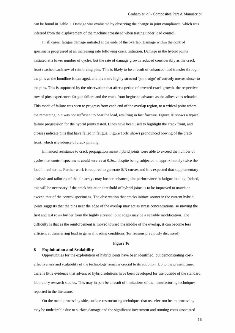
For the steel-GFRP joints tested, unaged advanced hybrid (P4) and control (C4) joints were both
shown to exhibit brittle failure, though the hybrid joints were much stronger. Figure 14 shows quasi-static
stress-displacement curves for similar aged and unaged joints. A typical curve is shown for each type of
joint. The aged hybrid joints displayed varying levels of ductile-progressive failure, contrasting the
brittle-catastrophic failure witnessed in quasi-static tests of unaged joints from the same batch. This multi-
stage failure comprised adherend disbonding, pin yielding, pin pullout and pin fracture at the base of the
pins. This change in behaviour was driven by a reduction in adhesive properties, and aligns with
observations made in previous unpublished work by the authors suggesting that changes in the baseline
strength of the adhesive bond have a significant effect on the resulting failure mode of the hybrid joints.
Here this is evidenced by the fact that in cases where the bonded joint strength was high relative to the pin
strength (unaged specimens) the observed failure was brittle and catastrophic. However, in cases where
the adhesive was weaker (aged specimens) the strength of the pins was sufficient to carry load after
disbonding and thus a progressive ductile failure was observed. Therefore, it is suggested that by
controlling the ratio of shear strength of the pin array relative to the adhesive shear strength, the failure
mechanism may be broadly manipulated.
Figure 14
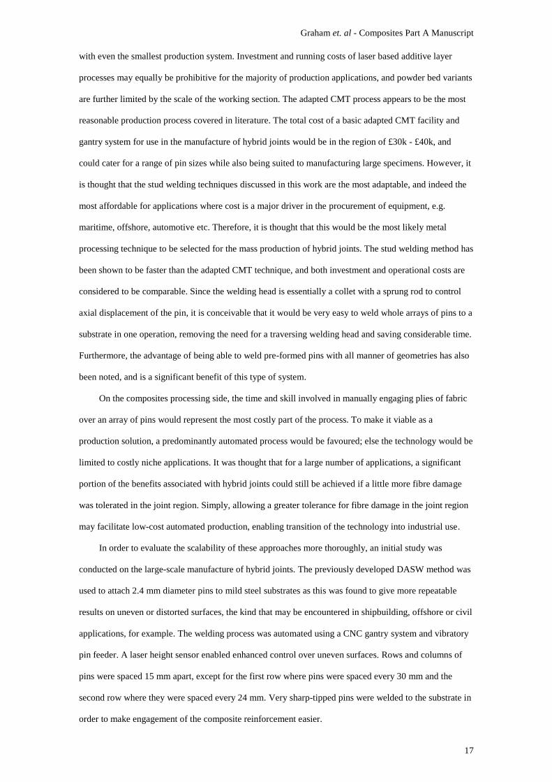
Figure 15 shows average peak values for the strength and energy absorption (approximated from the
area under the load-displacement curves) of unaged and aged joints. It was found that even when hybrid
joints of this type had been degraded, they still exhibited greater strength and energy absorption than the
undamaged control specimens. For control specimens the strength reduced by around 21%, and energy
absorption reduced by 35% as a result of the environmental ageing process. Hybrid joint strength and
energy absorption reduced by an average of 17% and 11% respectively. The apparent minor reduction in
energy absorption noted for hybrid joints was the result of the change in failure mode described above.
Figure 15
5.6 Fatigue
A total of four advanced hybrid and four control specimens were tested to provide an initial
indicative comparison of mechanical fatigue characteristics. Specific details on the hybrid configuration
Graham et. al - Composites Part A Manuscript
16
can be found in Table 1. Damage was evaluated by observing the change in joint compliance, which was
inferred from the displacement of the machine crosshead when testing under load control.
In all cases, fatigue damage initiated at the ends of the overlap. Damage within the control
specimens progressed at an increasing rate following crack initiation. Damage in the hybrid joints
initiated at a lower number of cycles, but the rate of damage growth reduced considerably as the crack
front reached each row of reinforcing pins. This is likely to be a result of enhanced load transfer through
the pins as the bondline is damaged, and the more highly stressed ‘joint edge’ effectively moves closer to
the pins. This is supported by the observation that after a period of arrested crack growth, the respective
row of pins experiences fatigue failure and the crack front begins to advance as the adhesive is reloaded.
This mode of failure was seen to progress from each end of the overlap region, to a critical point where
the remaining join was not sufficient to bear the load, resulting in fast fracture. Figure 16 shows a typical
failure progression for the hybrid joints tested. Lines have been used to highlight the crack front, and
crosses indicate pins that have failed in fatigue. Figure 16(b) shows pronounced bowing of the crack
front, which is evidence of crack pinning.
Enhanced resistance to crack propagation meant hybrid joints were able to exceed the number of
cycles that control specimens could survive at 0.5σu, despite being subjected to approximately twice the
load in real terms. Further work is required to generate S/N curves and it is expected that supplementary
analysis and tailoring of the pin arrays may further enhance joint performance in fatigue loading. Indeed,
this will be necessary if the crack initiation threshold of hybrid joints is to be improved to match or
exceed that of the control specimens. The observation that cracks initiate sooner in the current hybrid
joints suggests that the pins near the edge of the overlap may act as stress concentrations, so moving the
first and last rows further from the highly stressed joint edges may be a sensible modification. The
difficulty is that as the reinforcement is moved toward the middle of the overlap, it can become less
efficient at transferring load in general loading conditions (for reasons previously discussed).
Figure 16
6 Exploitation and Scalability
Opportunities for the exploitation of hybrid joints have been identified, but demonstrating cost-
effectiveness and scalability of the technology remains crucial to its adoption. Up to the present time,
there is little evidence that advanced hybrid solutions have been developed for use outside of the standard
laboratory research studies. This may in part be a result of limitations of the manufacturing techniques
reported in the literature.
On the metal processing side, surface restructuring techniques that use electron beam processing
may be undesirable due to surface damage and the significant investment and running costs associated
Graham et. al - Composites Part A Manuscript
17
with even the smallest production system. Investment and running costs of laser based additive layer
processes may equally be prohibitive for the majority of production applications, and powder bed variants
are further limited by the scale of the working section. The adapted CMT process appears to be the most
reasonable production process covered in literature. The total cost of a basic adapted CMT facility and
gantry system for use in the manufacture of hybrid joints would be in the region of £30k - £40k, and
could cater for a range of pin sizes while also being suited to manufacturing large specimens. However, it
is thought that the stud welding techniques discussed in this work are the most adaptable, and indeed the
most affordable for applications where cost is a major driver in the procurement of equipment, e.g.
maritime, offshore, automotive etc. Therefore, it is thought that this would be the most likely metal
processing technique to be selected for the mass production of hybrid joints. The stud welding method has
been shown to be faster than the adapted CMT technique, and both investment and operational costs are
considered to be comparable. Since the welding head is essentially a collet with a sprung rod to control
axial displacement of the pin, it is conceivable that it would be very easy to weld whole arrays of pins to a
substrate in one operation, removing the need for a traversing welding head and saving considerable time.
Furthermore, the advantage of being able to weld pre-formed pins with all manner of geometries has also
been noted, and is a significant benefit of this type of system.
On the composites processing side, the time and skill involved in manually engaging plies of fabric
over an array of pins would represent the most costly part of the process. To make it viable as a
production solution, a predominantly automated process would be favoured; else the technology would be
limited to costly niche applications. It was thought that for a large number of applications, a significant
portion of the benefits associated with hybrid joints could still be achieved if a little more fibre damage
was tolerated in the joint region. Simply, allowing a greater tolerance for fibre damage in the joint region
may facilitate low-cost automated production, enabling transition of the technology into industrial use.
In order to evaluate the scalability of these approaches more thoroughly, an initial study was
conducted on the large-scale manufacture of hybrid joints. The previously developed DASW method was
used to attach 2.4 mm diameter pins to mild steel substrates as this was found to give more repeatable
results on uneven or distorted surfaces, the kind that may be encountered in shipbuilding, offshore or civil
applications, for example. The welding process was automated using a CNC gantry system and vibratory
pin feeder. A laser height sensor enabled enhanced control over uneven surfaces. Rows and columns of
pins were spaced 15 mm apart, except for the first row where pins were spaced every 30 mm and the
second row where they were spaced every 24 mm. Very sharp-tipped pins were welded to the substrate in
order to make engagement of the composite reinforcement easier.
Graham et. al - Composites Part A Manuscript
18
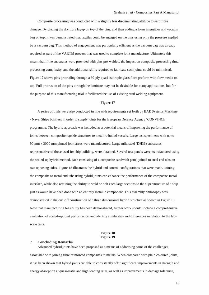
Composite processing was conducted with a slightly less discriminating attitude toward fibre
damage. By placing the dry fibre layup on top of the pins, and then adding a foam intensifier and vacuum
bag on top, it was demonstrated that textiles could be engaged on the pins using only the pressure applied
by a vacuum bag. This method of engagement was particularly efficient as the vacuum bag was already
required as part of the VARTM process that was used to complete joint manufacture. Ultimately this
meant that if the substrates were provided with pins pre-welded, the impact on composite processing time,
processing complexity, and the additional skills required to fabricate such joints could be minimised.
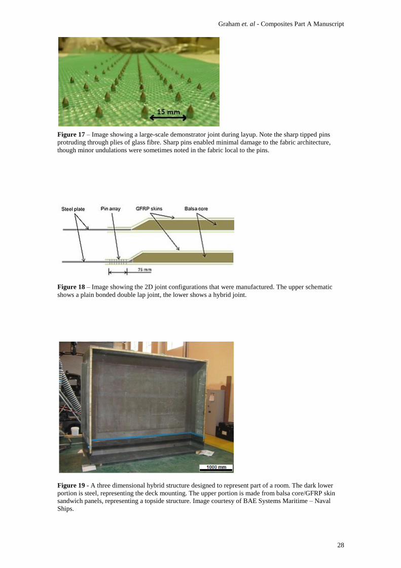
Figure 17 shows pins protruding through a 30-ply quasi-isotropic glass fibre preform with flow media on
top. Full protrusion of the pins through the laminate may not be desirable for many applications, but for
the purpose of this manufacturing trial it facilitated the use of existing stud welding equipment.
Figure 17
A series of trials were also conducted in line with requirements set forth by BAE Systems Maritime
- Naval Ships business in order to supply joints for the European Defence Agency ‘CONVINCE’
programme. The hybrid approach was included as a potential means of improving the performance of
joints between composite topside structures to metallic-hulled vessels. Large test specimens with up to
90 mm x 3000 mm pinned joint areas were manufactured. Large mild steel (DH36) substrates,
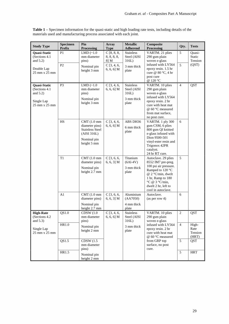
representative of those used for ship building, were obtained. Several test panels were manufactured using
the scaled-up hybrid method, each consisting of a composite sandwich panel joined to steel end tabs on
two opposing sides. Figure 18 illustrates the hybrid and control configurations that were made. Joining
the composite to metal end tabs using hybrid joints can enhance the performance of the composite-metal
interface, while also retaining the ability to weld or bolt each large sections to the superstructure of a ship
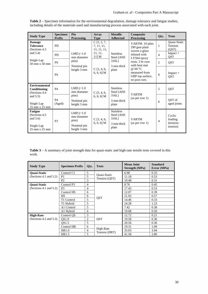
just as would have been done with an entirely metallic component. This assembly philosophy was
demonstrated in the one-off construction of a three dimensional hybrid structure as shown in Figure 19.
Now that manufacturing feasibility has been demonstrated, further work should include a comprehensive
evaluation of scaled-up joint performance, and identify similarities and differences in relation to the lab-
scale tests.
Figure 18
Figure 19
7 Concluding Remarks
Advanced hybrid joints have been proposed as a means of addressing some of the challenges
associated with joining fibre reinforced composites to metals. When compared with plain co-cured joints,
it has been shown that hybrid joints are able to consistently offer significant improvements in strength and
energy absorption at quasi-static and high loading rates, as well as improvements in damage tolerance,
Graham et. al - Composites Part A Manuscript
19
environmental durability and mechanical fatigue performance. One of the key advantages with hybrid
joints is the potential to tailor joint performance, particularly with respect to failure modes. Changes in
the baseline strength of the adhesive were found to have a significant effect on the resulting failure mode
of the hybrid joints. Failure is highly complex, but on a basic level it appears that by controlling the ratio
of shear strength of the pin array relative to the adhesive shear strength, failure modes may be broadly
manipulated. Further testing and modelling would ideally lead to an optimal shear strength ratio or design
rule that engineers could apply for a particular configuration of hybrid joint. This ratio may be different
for quasi-static and high-rate loading; since adhesives tend to exhibit higher strength when tested at high
loading rates, it may be necessary to modify the shear strength of the pin array accordingly when
designing for progressive failure.
For the lab tests presented in this work, all of the benefits associated with advanced hybrid joints
were achieved with virtually zero net weight gain relative to the plain co-cured joints, making advanced
hybrid joints more attractive than bolted joints where disassembly is not required. Indeed, advanced
hybrid joints could facilitate a weight reduction compared with bonded joints since the increased
performance may enable a reduction in joint size. In a situation where disassembly is required, the
principle of using hybrid joints to attach metal end tabs for metal-metal joining has been demonstrated.
A novel low-cost and scalable approach to advanced hybrid joint manufacture was developed and
successfully employed for the production of large naval structures. This involved an automated stud
welding rig, and hands-free engagement of the composite layup on the interlocking pin array using
pressure applied via a vacuum bag.
The current work has shown potential for attractive performance gains and weight savings in the
immediate future, however, considerable experimental and modelling work is still required to obtain a
detailed understanding of advanced hybrid joint performance and failure, as well as sensitivity to various
geometric and material parameters. Furthermore, as specific applications begin to be addressed it will be
necessary to draw more direct comparisons between advanced hybrid specimens and other competing
joining systems, which may include secondary bonded joints rather than simple co-cured specimens.

Graham et. al - Composites Part A Manuscript
20
Acknowledgements
The authors gratefully acknowledge support from the EPSRC in providing funding for the MiNMaT
Industrial Doctoral Centre (IDC) at the University of Surrey along with support from the 1851 Royal
Commission in awarding D. Graham an Industrial Fellowship. Support from the European Defence
Agency ‘CONVINCE’ programme, Professor Alan Groves (dstl), Dr Malcolm Robb (BAE Systems
Maritime – Naval Ships) and Dr Tim Williams (BAE Systems Maritime – Naval Ships) is also
acknowledged.
References [1] Camanho PP, Matthews FL. Stress analysis and strength prediction of mechanically fastened joints in FRP: A
review. Composites Part A: Applied Science and Manufacturing. 1997;28(6):529-47.
[2] Hart-Smith LJ. Design methodology for bonded-bolted composite joints. Long Beach, California: Douglas
Aircraft Company; 1982.
[3] Kelly G. Load transfer in hybrid (bonded/bolted) composite single-lap joints. Composite Structures. 2005
6;69(1):35-43.
[4] Fu M, Mallick PK. Fatigue of hybrid (adhesive/bolted) joints in SRIM composites. Int J Adhes Adhes.
2001;21(2):145-59.
[5] Barut A, Madenci E. Analysis of bolted–bonded composite single-lap joints under combined in-plane and
transverse loading. Composite Structures. 2009 5;88(4):579-94.
[6] Ingalls shipbuilding delivers composite deckhouse for zumwalt (DDG 1000) [Internet].; 09 October 2012.
Available from: http://www.globenewswire.com/newsarchive/hii/pages/news_releases.html?d=10007801.
[7] McGeorge D. EUCLID RTP3.21: Survivability, durability and performance of naval composite structures.
Technical Report. Høvik, Norway: DET NORSKE VERITAS; 2004. Report No.: DNV-0-C-DT1.P.
[8] KaZaK makes UAV wings. Reinforced Plast. 2008 6;52(6):6.
[9] Hoang-Ngoc C, Paroissien E. Simulation of single-lap bonded and hybrid (bolted/bonded) joints with flexible
adhesive. Int J Adhes Adhes. 2010 4;30(3):117-29.
[10] McCarthy MA, Lawlor VP, Stanley WF, McCarthy CT. Bolt-hole clearance effects and strength criteria in
single-bolt, single-lap, composite bolted joints. Composites Sci Technol. 2002 8;62(10–11):1415-31.
[11] Matsuzaki R, Shibata M, Todoroki A. Improving performance of GFRP/aluminum single lap joints using
bolted/co-cured hybrid method. Composites Part A: Applied Science and Manufacturing. 2008 2;39(2):154-63.
[12] Kellar EJC, Smith F. Energy absorbing joints between fibre reinforced plastics and metals. Joining plastics; 25-
26 April; London. ; 2006.
[13] Parkes PN, Butler R, Almond DP. Growth of damage in additively manufactured metal-composite joints.
ECCM15 - 15th European Conference on Composite Materials; 24-28 June; Venice, Italy. ; 2012.
[14] Ucsnik S, Scheerer M, Zaremba S, Pahr DH. Experimental investigation of a novel hybrid metal-composite
joining technology. Composites Part A: Applied Science and Manufacturing. 2010(41):369-374.
[15] Mouring SE, Janowski M, Louca LA, Brambleby RJ. Structural performance of comeld hybrid metal-to-
composite joints. Twenty second international offshore and polar engineering conference; 17-22 June 2012; Rhodes,
Greece. www.isope.org; 2012.
[16] Houldcroft PT. Unshielded and short-time arc processes. In: Welding Processes. Cambridge University Press;
1967. p. 101.
[17] Zhang K, Yang Z, Li Y. A method for predicting the curing residual stress for CFRP/Al adhesive single-lap
joints. Int J Adhes Adhes. 2013 10;46(0):7-13.
[18] Adamvalli M, Parameswaran V. Dynamic strength of adhesive single lap joints at high temperature. Int J Adhes
Adhes. 2008 9;28(6):321-7.
[19] Comyn J. Durability of structural adhesives. Kinloch AJ, editor. Applied Science Publishers; 1983.
[20] Kelly G. Quasi-static strength and fatigue life of hybrid (bonded/bolted) composite single-lap joints. Composite
Structures. 2006 1;72(1):119-29.
Graham et. al - Composites Part A Manuscript
21
Figure 1 – Schematic of an advanced hybrid single lap joint (section view). Advanced hybrid joints
combine adhesive bonding with an interlocking array of mechanical reinforcement.
Figure 2 – An illustration of the drop-weight test setup. Single-lap joints were clamped between two
6 mm thick plates, each plate had square aperture in the centre (shown here in section view).
Figure 3 - Typical quasi-static load vs. displacement curves for co-cured (C1) and hybrid double-lap joint
(P1 & P2) specimens.
Graham et. al - Composites Part A Manuscript
22
Figure 4 - A failed hybrid P2 joint. Note how the pins have yielded and been pulled out of the composite
material. The pins were originally normal to the surface of the metal adherend. The stepped overlap
region was not bonded, and was usually removed completely prior to testing.
Figure 5 - Typical stress vs. displacement curves for the P3 steel-GFRP hybrid (pinned) and plain co-
cured (control) single-lap joints. Joints were loaded in tensile lap-shear configuration.
Figure 6 - Typical stress vs. displacement curves for steel-GFRP hybrid (HS) and plain co-cured (Control
HS) single-lap joints. Joints were loaded in tensile lap-shear configuration.
Graham et. al - Composites Part A Manuscript
23
Figure 7 - Typical stress vs. displacement curves for aluminium hybrid (A1 Hybrid), aluminium control
(A1 Control), titanium hybrid (T1 Hybrid) and titanium control (T1 Control) specimens.
Figure 8 – Typical stress vs. displacement curves for quasi-static (QS) and high-rate (HR) tests of control
joints, and hybrid joints with either 1.0 mm or 1.5 mm diameter pins. High-rate data is plotted just beyond
peak stress, after which point the data became unusable due to noise caused by large reflections of the
stress wave.
Graham et. al - Composites Part A Manuscript
24
Figure 9 – A summary showing average strength data for quasi-static and high rate tests. Hybrid and
control joint showed rate sensitivity, but the peak stresses measured for hybrid joints tested at high
loading rates were higher than expected.
Figure 10 – Failure sequence of a QS1.5 hybrid joint tested at a quasi-static rate. a) disbonding initiated
at both ends of the overlap, the cracks arrested at the first row of pins, b) disbonding advanced at the
composite end of the overlap where the stiffness mismatch was highest, c) disbonding advanced in a
stepwise fashion following another period of arrested crack growth, d) disbonding was close to the critical
level typically resulting in complete fracture of the primary bondline when delamination started to occur
in the composite material, pin and substrate yielding were also apparent, e) Extensive delamination was
observed in the composite, as well as significant pin and substrate yielding in the final stages.
Graham et. al - Composites Part A Manuscript
25
Figure 11 – Failure sequence of a HR1.5 hybrid joint tested at high rate. Images are at 44 µs intervals
within the visible failure sequence, which lasted approximately 175 µs in total. A high speed camera was
used to capture failure of the joints tested at high loading rates. Disbonding initiated at the composite
adherend end of the overlap, shortly followed by disbonding at the steel adherend end. Failure progressed
with pin and substrate yielding, as well as extensive delamination within the composite material.
Figure 12 – A comparison between control (C9) and hybrid (P8) joints impacted at 13J and 14J,
respectively. The impact site is the indented region close to the cross. Note the different levels of
disbonding, and the way that damage has arrested close to the pins in the hybrid specimen.
Graham et. al - Composites Part A Manuscript
26
Figure 13 – Residual strength vs. impact energy for PS and control specimens. The hybrid specimens
showed no loss of strength within the impact energy range tested, though compliance was increased as a
result of the compromised primary bondline.
Figure 14 – Data showing the effect of environmental aging on the stress vs. displacement response of
hybrid (P4) and control (C4) stainless steel-GFRP joints. A reduction in adhesive properties caused the
failure mode of hybrid joints to become more progressive.

Graham et. al - Composites Part A Manuscript
27
Figure 15 – Nominal shear strength and energy to failure for hybrid and control stainless steel-GFRP
joints that were environmentally aged. Undamaged, as manufactured joints are included for comparison.
Figure 16 – Four images illustrating crack propagation within a hybrid joint subjected to cyclic loading.
Lines have been added to indicate the location of the crack front, and crosses to indicate where pins have
failed at the base due to fatigue.
Graham et. al - Composites Part A Manuscript
28
Figure 17 – Image showing a large-scale demonstrator joint during layup. Note the sharp tipped pins
protruding through plies of glass fibre. Sharp pins enabled minimal damage to the fabric architecture,
though minor undulations were sometimes noted in the fabric local to the pins.
Figure 18 – Image showing the 2D joint configurations that were manufactured. The upper schematic
shows a plain bonded double lap joint, the lower shows a hybrid joint.
Figure 19 - A three dimensional hybrid structure designed to represent part of a room. The dark lower
portion is steel, representing the deck mounting. The upper portion is made from balsa core/GFRP skin
sandwich panels, representing a topside structure. Image courtesy of BAE Systems Maritime – Naval
Ships.
Graham et. al - Composites Part A Manuscript
29
Table 1 – Specimen information for the quasi-static and high loading rate tests, including details of the
materials used and manufacturing process associated with each joint.
Study Type Specimen
Prefix
Pin
Processing
Array
Type
Metallic
Adherend
Composite
Processing Qty. Tests
Quasi-Static
(Sections 4.1
and 5.2)
Double Lap
25 mm x 25 mm
P1 LMD (~1.0
mm diameter
pins)
Nominal pin
height 3 mm
C [8, 8, 8,
8, 8, 8, 8,
8] M
Stainless
Steel (AISI
316L)
3 mm thick
plate
VARTM. 21 plies
290 gsm plain
woven e-glass
infused with LY564
epoxy resin. 1.5 hr
cure @ 80 °C, 4 hr
post cure
@ 120 °C
5 Quasi-
Static
Tension
(QST) P2 C [3, 4, 6,
6, 6, 6] M
5
Quasi-Static
(Sections 4.1
and 5.2)
Single Lap
25 mm x 25 mm
P3 LMD (~1.0
mm diameter
pins)
Nominal pin
height 3 mm
C [3, 4, 6,
6, 6, 6] M
Stainless
Steel (AISI
316L)
3 mm thick
plate
VARTM. 10 plies
290 gsm plain
woven e-glass
infused with LY564
epoxy resin. 2 hr
cure with heat mat
@ 60 °C measured
from mat surface,
no post cure.
4
QST
HS CMT (1.0 mm
diameter pins)
Stainless Steel
(AISI 316L)
Nominal pin
height 5 mm
C [3, 4, 6,
6, 6, 6] M
ABS DH36
6 mm thick
plate
VARTM. 1 ply 300
gsm CSM, 6 plies
800 gsm QI knitted
e-glass infused with
Dion 9500-501
vinyl-ester resin and
Trigonox 42PR
catalyst.
24 hr RT cure.
6
T1 CMT (1.0 mm
diameter pins)
Nominal pin
height 2.7 mm
C [3, 6, 6,
6, 6, 3] M
Titanium
(6Al-4V)
3 mm thick
plate
Autoclave. 29 plies
8552 IM7 pre-preg.
100 psi air pressure.
Ramped to 120 °C
@ 2 °C/min, dwelt
1 hr, Ramp to 180
°C @ 3 °C/min,
dwelt 2 hr, left to
cool in autoclave.
5
A1 CMT (1.0 mm
diameter pins)
Nominal pin
height 2.7 mm
C [3, 6, 6,
6, 6, 3] M
Aluminium
(AA7050)
4 mm thick
plate
Autoclave.
(as per row 4)
6
High-Rate
(Sections 4.2
and 5.3)
Single Lap
25 mm x 25 mm
QS1.0 CDSW (1.0
mm diameter
pins)
Nominal pin
height 2 mm
C [3, 4, 6,
6, 6, 6] M
Stainless
Steel (AISI
316L)
3 mm thick
plate
VARTM. 10 plies
290 gsm plain
woven e-glass
infused with LY564
epoxy resin. 2 hr
cure with heat mat
@ 60 °C measured
from GRP top
surface, no post
cure.
2 QST
HR1.0 4 High-
Rate
Tension
(HRT)
QS1.5 CDSW (1.5
mm diameter
pins)
Nominal pin
height 2 mm
5 QST
HR1.5 5 HRT
Graham et. al - Composites Part A Manuscript
30
Table 2 – Specimen information for the environmental degradation, damage tolerance and fatigue studies,
including details of the materials used and manufacturing process associated with each joint.
Study Type Specimen
Prefix
Pin
Processing
Array
Type
Metallic
Adherend
Composite
Processing Qty. Tests
Damage
Tolerance
(Sections 4.3
and 5.4)
Single Lap
50 mm x 50 mm
PD
LMD (~1.0
mm diameter
pins)
Nominal pin
height 3 mm
C [5, 5, 7,
7, 11, 11,
11, 11, 11,
11, 11,
11] M Stainless
Steel (AISI
316L)
3 mm thick
plate
VARTM. 10 plies
290 gsm plain
woven e-glass
infused with
LY564 epoxy
resin. 2 hr cure
with heat mat
@ 60 °C
measured from
GRP top surface,
no post cure.
1
Quasi-Static
Tension
(QST)
PD 4 Impact +
QST
PS
C [3, 4, 6,
6, 6, 6] M
2 QST
PS 8 Impact +
QST
Environmental
Conditioning
(Sections 4.4
and 5.5)
Single Lap
25 mm x 25 mm
P4 LMD (~1.0
mm diameter
pins)
Nominal pin
height 3 mm
C [3, 4, 6,
6, 6, 6] M
Stainless
Steel (AISI
316L)
3 mm thick
plate
VARTM
(as per row 1)
5 QST
P4
(Aged) 6
QST of
aged joints
Fatigue
(Sections 4.5
and 5.6)
Single Lap
25 mm x 25 mm
P3
LMD (~1.0
mm diameter
pins)
Nominal pin
height 3 mm
C [3, 4, 6,
6, 6, 6] M
Stainless
Steel (AISI
316L)
3 mm thick
plate
VARTM
(as per row 1) 4
Cyclic
loading
(tension-
tension)
Table 3 – A summary of joint strength data for quasi-static and high-rate tensile tests covered in this
work.
Study Type Specimen Prefix Qty. Tests Mean Joint
Strength (MPa)
Standard
Error (MPa)
Quasi-Static
(Sections 4.1 and 5.2)
Control C1 5 Quasi-Static
Tension (QST)
6.98 0.33
P1 5 11.18 0.53
P2 3 10.48 0.31
Quasi-Static
(Sections 4.1 and 5.2)
Control P3 4
QST
8.76 0.45
P3 4 17.43 0.53
Control HS 6 12.07 0.39
HS 6 21.92 0.57
T1 Control 5 14.46 0.33
T1 Hybrid 5 24.28 1.23
A1 Control 5 7.42 0.38
A1 Hybrid 6 19.08 0.50
High-Rate
(Sections 4.2 and 5.3)
Control QS 3
QST
12.72 0.21
QS1.0 2 19.58 0.36
QS1.5 5 20.56 0.30
Control HR 6 High-Rate
Tension (HRT)
19.31 1.09
HR1.0 4 35.03 3.94
HR1.5 5 41.58 2.80