Embed Size (px)
Citation preview
Client logo
THE DESIGN OF SECOND PENANG BRIDGE Prof. Fan Chao Meng
Vice Director, China Highway Planning and Design Institute
Dr. Robin Sham
Global Long Span and Specialty Bridges Director, AECOM
Ir. Fang Zhenru
Executive Project Director, CHEC Construction (M) Sdn Bhn
Nov-11
Client logo
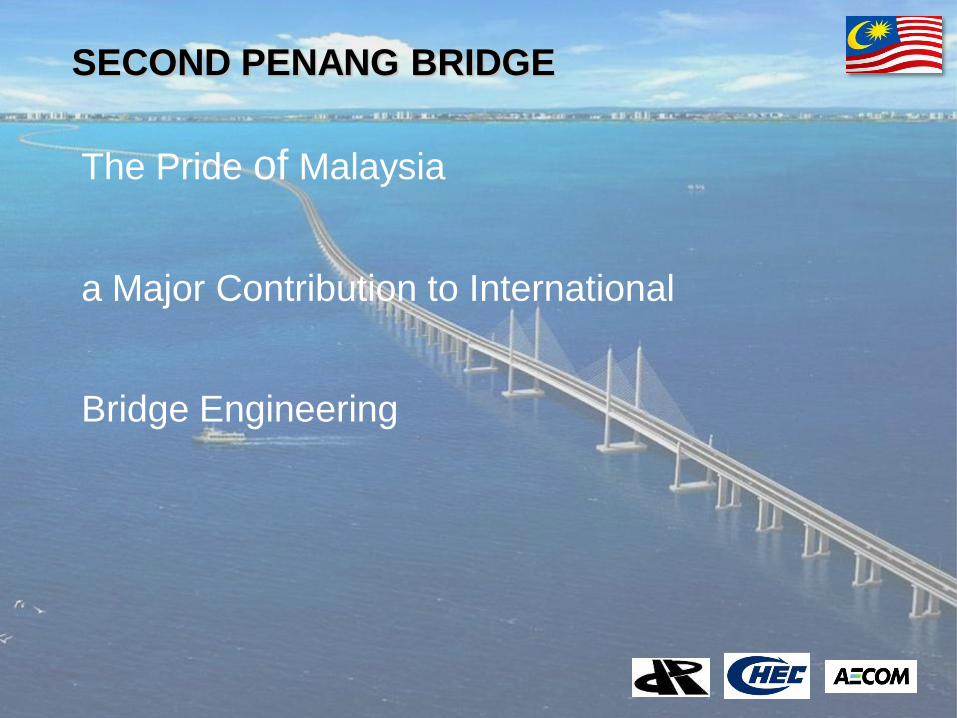
SECOND PENANG BRIDGE
The Pride of Malaysia a Major Contribution to International Bridge Engineering
Client logo
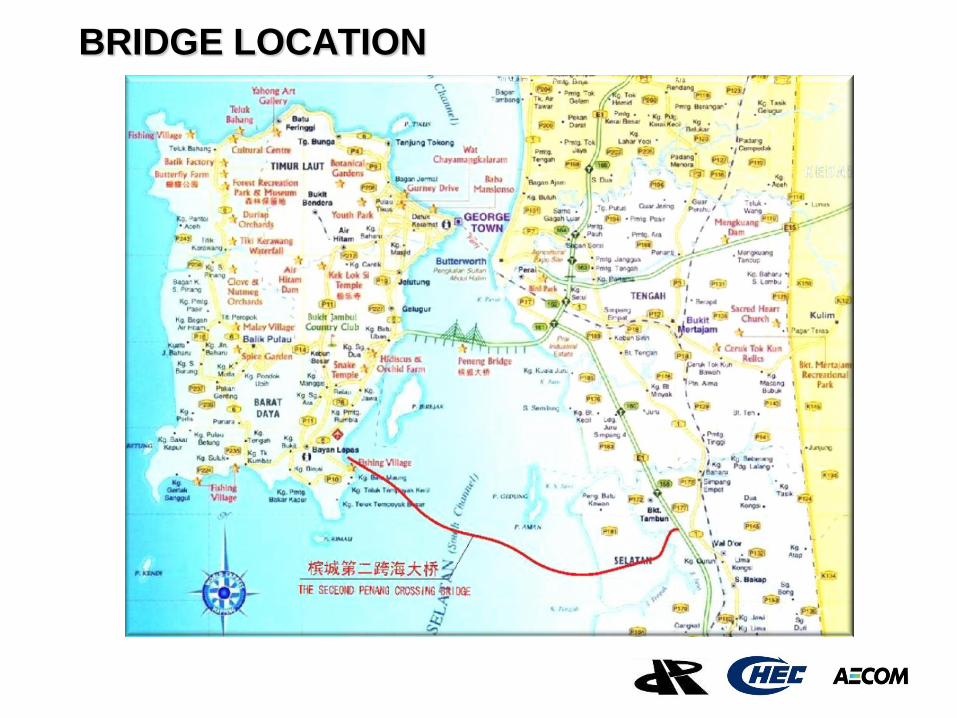
BRIDGE LOCATION
Client logo
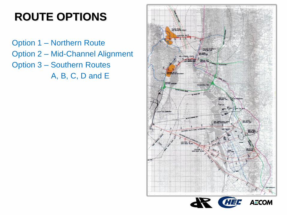
ROUTE OPTIONS
Option 1 – Northern Route
Option 2 – Mid-Channel Alignment
Option 3 – Southern Routes
A, B, C, D and E
Client logo
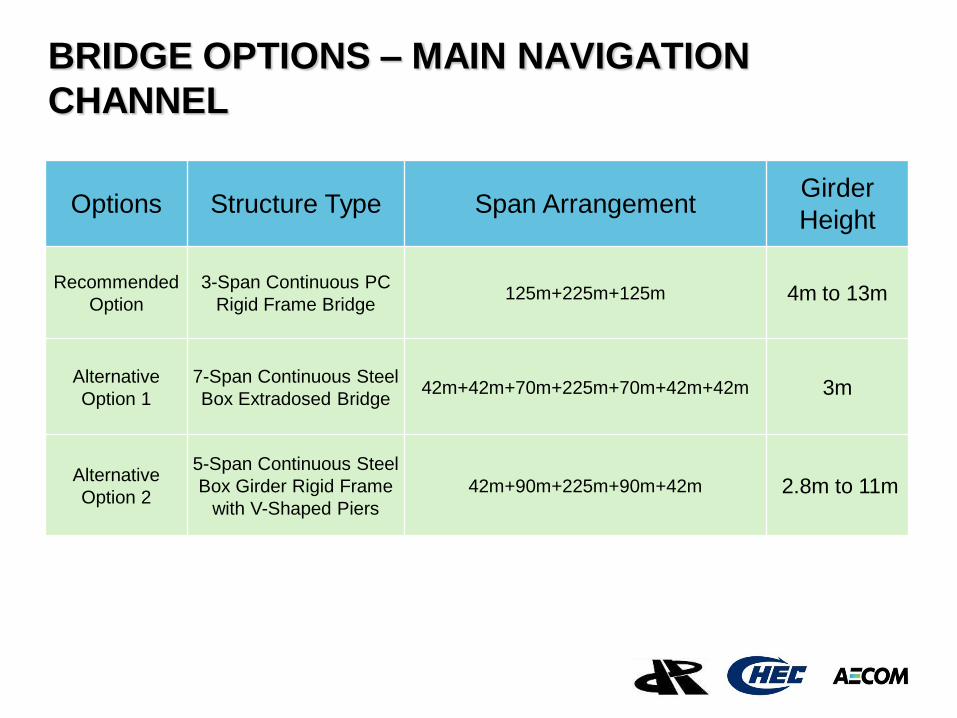
BRIDGE OPTIONS – MAIN NAVIGATION
CHANNEL
Options Structure Type Span Arrangement
Girder
Height
Recommended
Option 3-Span Continuous PC
Rigid Frame Bridge 125m+225m+125m 4m to 13m
Alternative
Option 1 7-Span Continuous Steel
Box Extradosed Bridge 42m+42m+70m+225m+70m+42m+42m 3m
Alternative
Option 2
5-Span Continuous Steel
Box Girder Rigid Frame
with V-Shaped Piers 42m+90m+225m+90m+42m 2.8m to 11m
Client logo
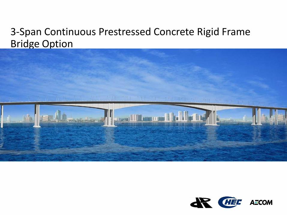
3-Span Continuous Prestressed Concrete Rigid Frame Bridge Option
Client logo
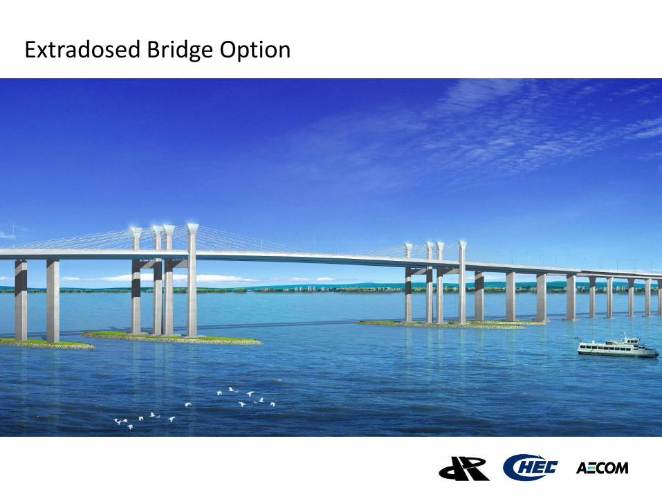
Extradosed Bridge Option
Client logo
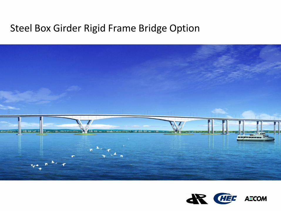
Steel Box Girder Rigid Frame Bridge Option
Client logo
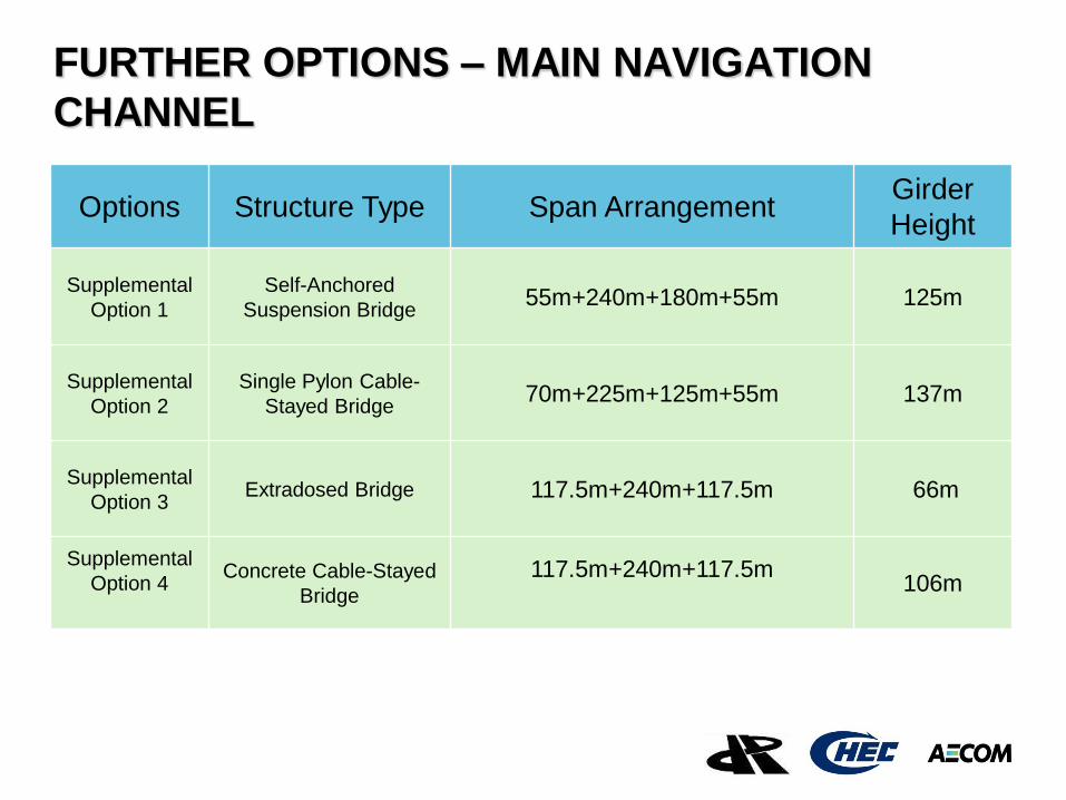
FURTHER OPTIONS – MAIN NAVIGATION
CHANNEL
Options Structure Type Span Arrangement
Girder
Height
Supplemental
Option 1
Self-Anchored
Suspension Bridge 55m+240m+180m+55m 125m
Supplemental
Option 2
Single Pylon Cable-
Stayed Bridge 70m+225m+125m+55m 137m
Supplemental
Option 3 Extradosed Bridge 117.5m+240m+117.5m 66m
Supplemental
Option 4
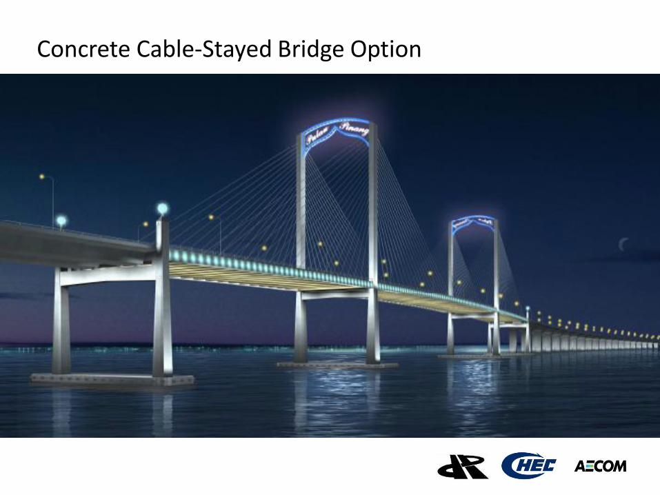
Concrete Cable-Stayed
Bridge
117.5m+240m+117.5m
106m
Client logo
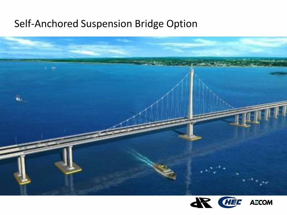
Self-Anchored Suspension Bridge Option
Client logo
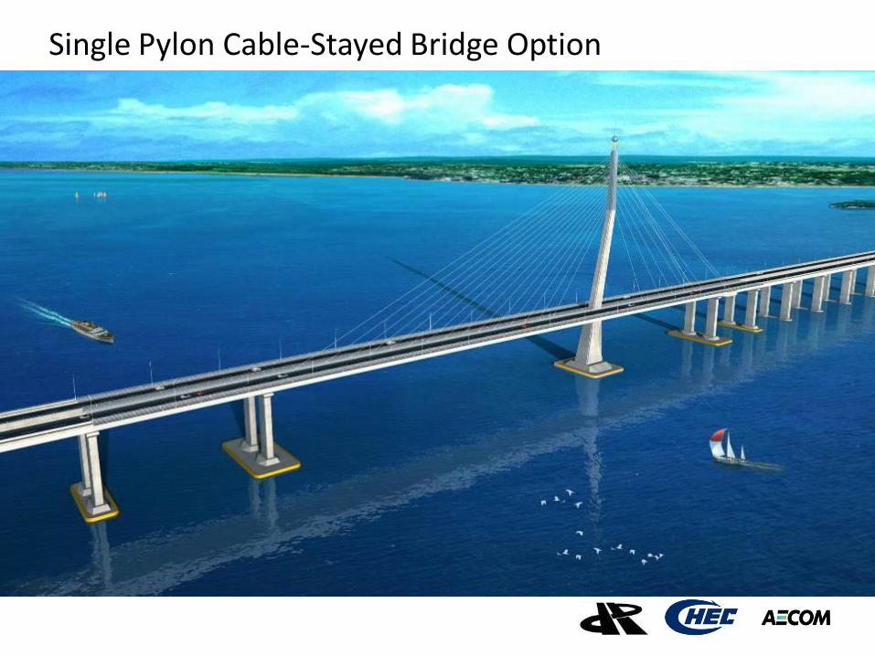
Single Pylon Cable-Stayed Bridge Option
Client logo
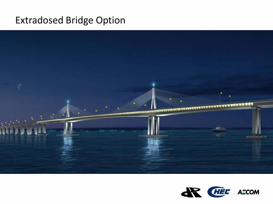
Extradosed Bridge Option
Client logo
Concrete Cable-Stayed Bridge Option
Client logo
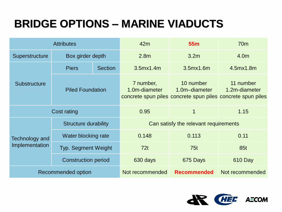
BRIDGE OPTIONS – MARINE VIADUCTS
Attributes 42m 55m 70m
Superstructure Box girder depth 2.8m 3.2m 4.0m
Substructure
Piers Section 3.5mx1.4m 3.5mx1.6m 4.5mx1.8m
Piled Foundation
7 number,
1.0m-diameter
concrete spun piles
10 number
1.0m–diameter
concrete spun piles
11 number
1.2m-diameter
concrete spun piles
Cost rating 0.95 1 1.15
Technology and
Implementation
Structure durability Can satisfy the relevant requirements
Water blocking rate 0.148 0.113 0.11
Typ. Segment Weight 72t 75t 85t
Construction period 630 days 675 Days 610 Day
Recommended option Not recommended Recommended Not recommended
Client logo
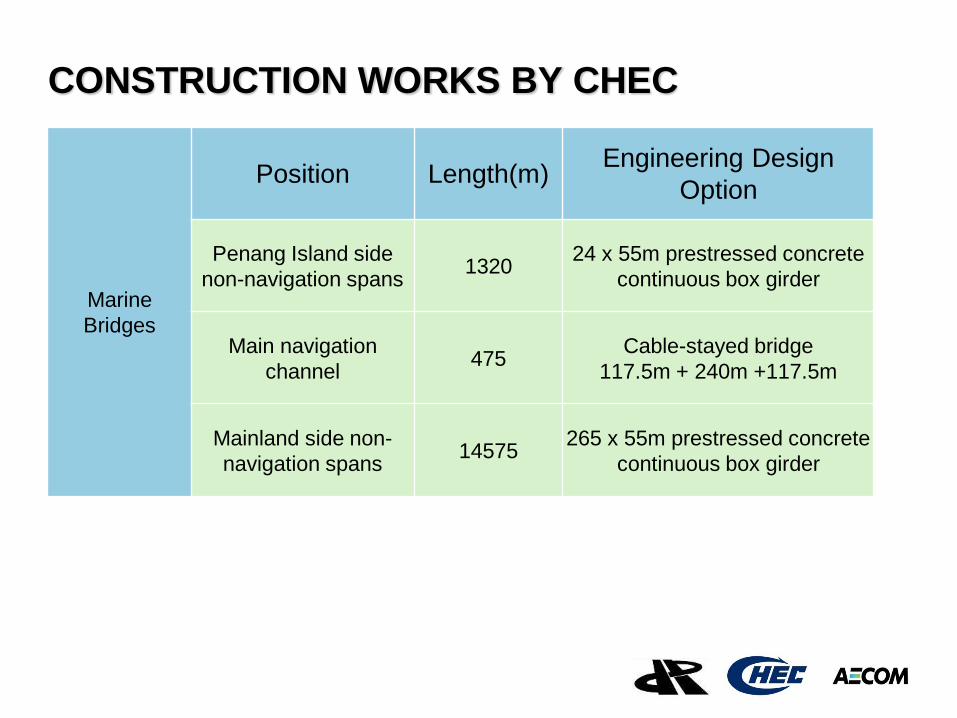
CONSTRUCTION WORKS BY CHEC
Marine
Bridges
Position Length(m) Engineering Design
Option
Penang Island side
non-navigation spans 1320
24 x 55m prestressed concrete
continuous box girder
Main navigation
channel 475
Cable-stayed bridge
117.5m + 240m +117.5m
Mainland side non-
navigation spans 14575
265 x 55m prestressed concrete
continuous box girder
Client logo
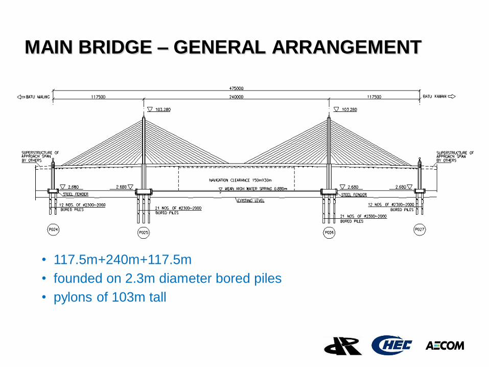
MAIN BRIDGE – GENERAL ARRANGEMENT
• 117.5m+240m+117.5m
• founded on 2.3m diameter bored piles
• pylons of 103m tall
Client logo
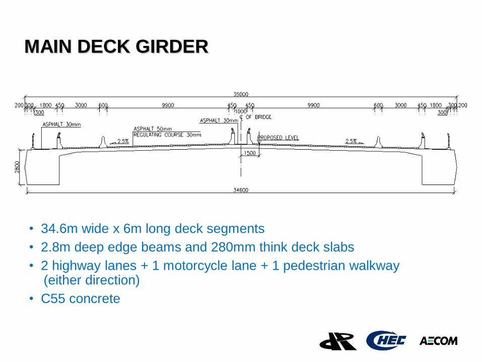
MAIN DECK GIRDER
• 34.6m wide x 6m long deck segments
• 2.8m deep edge beams and 280mm think deck slabs
• 2 highway lanes + 1 motorcycle lane + 1 pedestrian walkway (either direction)
• C55 concrete
Client logo
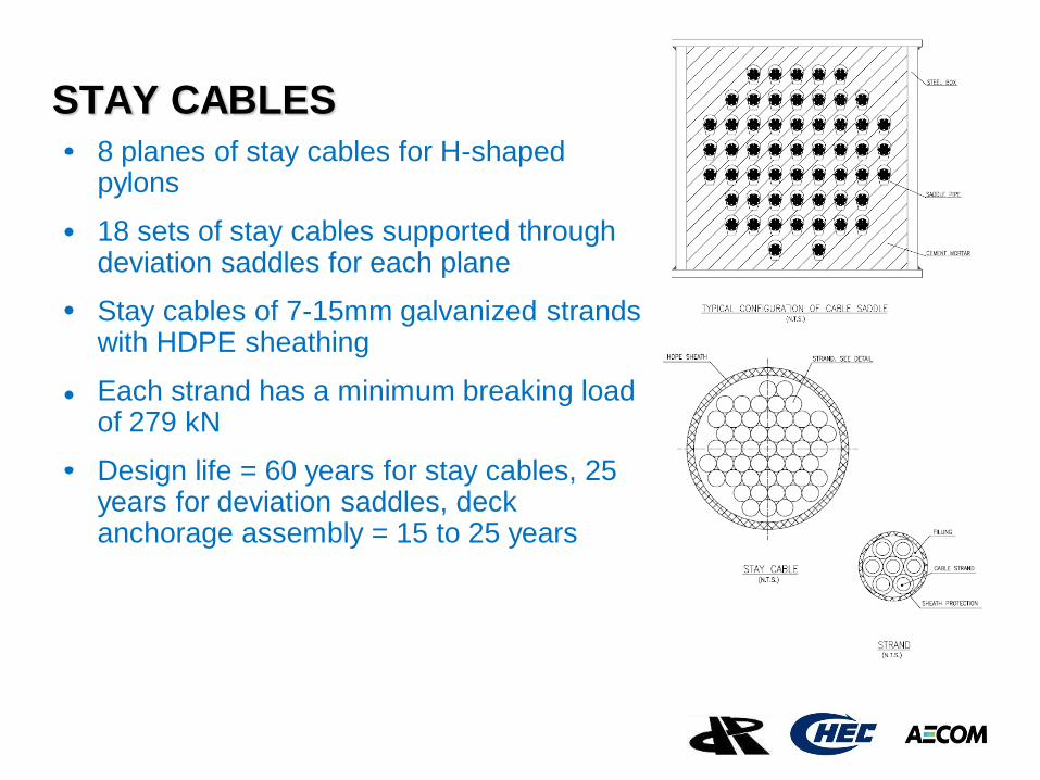
STAY CABLES
8 planes of stay cables for H-shaped pylons
18 sets of stay cables supported through deviation saddles for each plane
Stay cables of 7-15mm galvanized strands with HDPE sheathing
Each strand has a minimum breaking load of 279 kN
Design life = 60 years for stay cables, 25 years for deviation saddles, deck anchorage assembly = 15 to 25 years
Client logo
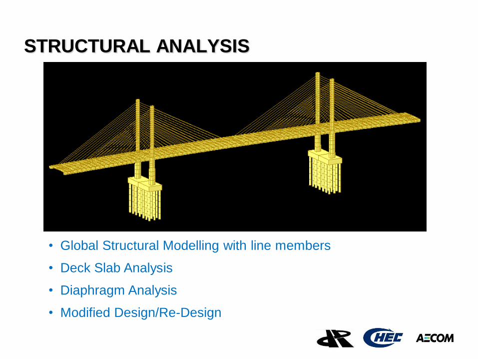
STRUCTURAL ANALYSIS
• Global Structural Modelling with line members
• Deck Slab Analysis
• Diaphragm Analysis
• Modified Design/Re-Design
Client logo
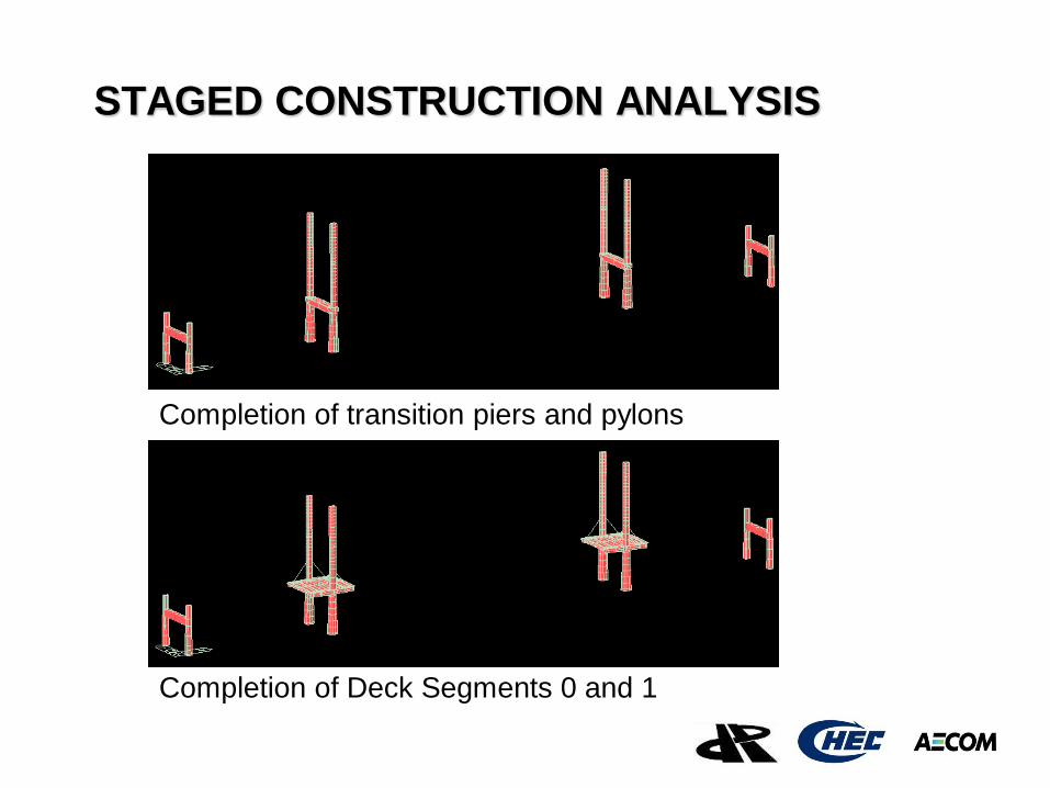
STAGED CONSTRUCTION ANALYSIS
Completion of transition piers and pylons
Completion of Deck Segments 0 and 1
Client logo
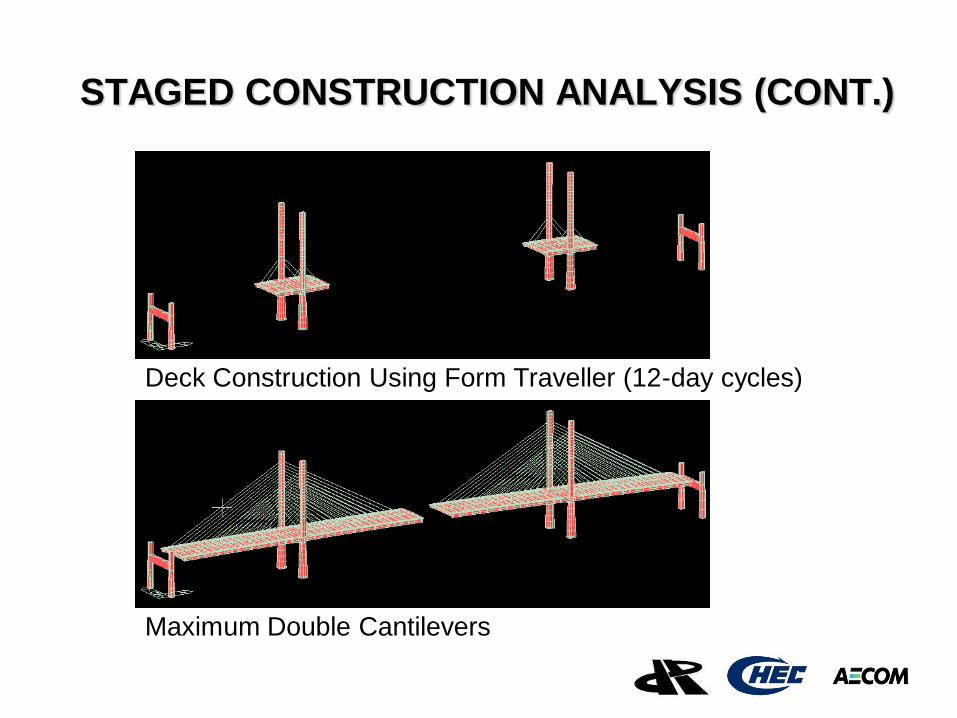
STAGED CONSTRUCTION ANALYSIS (CONT.)
Deck Construction Using Form Traveller (12-day cycles)
Maximum Double Cantilevers
Client logo
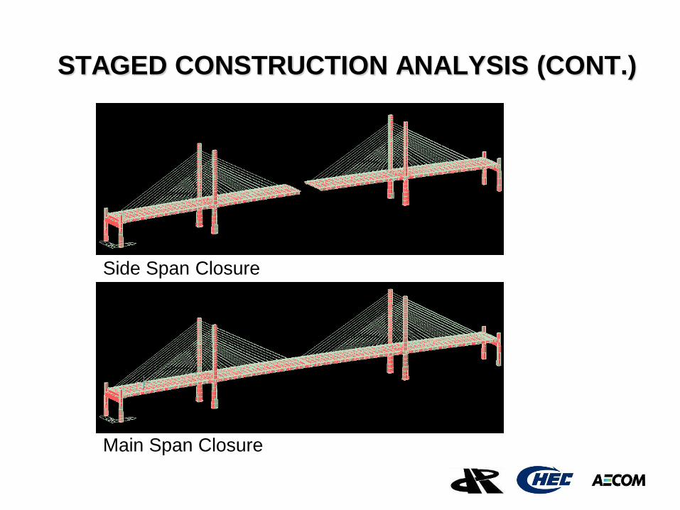
STAGED CONSTRUCTION ANALYSIS (CONT.)
Side Span Closure
Main Span Closure
Client logo
MODIFIED DESIGN Make provision for two outer motorcycle lanes to highway traffic lanes
• Global Structural Analyses for Construction Stages and at Bridge Completion
• Beam Model – both edge beams and slabs are simulated using beam elements in the longitudinal directions.
• Plate Model – slabs in beam model are modeled using plate elements to account for the shear lag effect
• Both models took full account of method and sequence of construction, temporary loads, permanent loads, traffic loads, wind loads, seismic loads, material properties and time-dependent effects.
Client logo
DESIGN BRIEF, MAY 2010
• Prestressed Concrete Members during construction tensile limit of 1MPa and compressive limit of 0.4fcu
• Reinforced Concrete Members (slabs, transition piers, pylons) during construction crack width limits
• Ultimate Limit State (ULS) axial force-bending moment interaction
• Stay Cables limiting stress of 0.45 GUTS • Deviation Saddles limiting stress of 0.70 GUTS
Client logo
SEISMIC ANALYSIS AND DESIGN
• Principles and procedures in AASHTO 2004
• Design Earthquake with a return period of 475 years
• Maximum Credible Earthquake with a return period of 2500 years
• Linear Spectrum Analysis with SRSS
• Nonlinear Time History Analysis
Client logo
SITE-SPECIFIC SEISMIC HAZARD
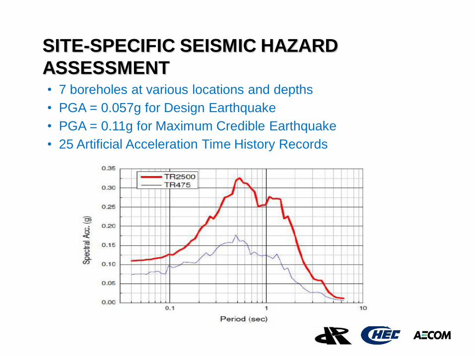
ASSESSMENT • 7 boreholes at various locations and depths
• PGA = 0.057g for Design Earthquake
• PGA = 0.11g for Maximum Credible Earthquake
• 25 Artificial Acceleration Time History Records
Client logo
BRIDGE AERODYNAMICS AND WIND
TUNNEL TESTING
• Wind Tunnel at Southwest Jiaotung University, China
• Static and Dynamic Section Model Testing for Bridge Deck
• Aeroelastic Model Testing of a Freestanding Bridge Pylon (scale 1:40)
• Aeroelastic Bridge Model Testing of Two Critical Erection Stages as well as at Bridge Completion (scale 1:60)
- maximum double cantilevers before side span closure - maximum single cantilever after side span closure
Client logo
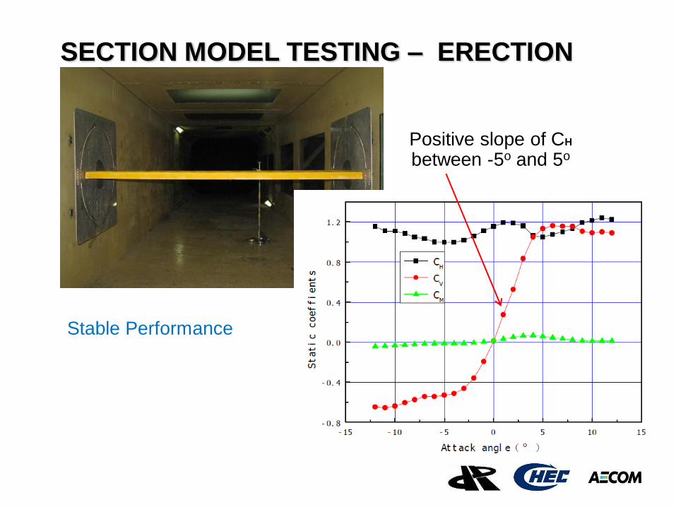
Stable Performance
SECTION MODEL TESTING – ERECTION
Positive slope of CH
between -5o and 5o
Client logo
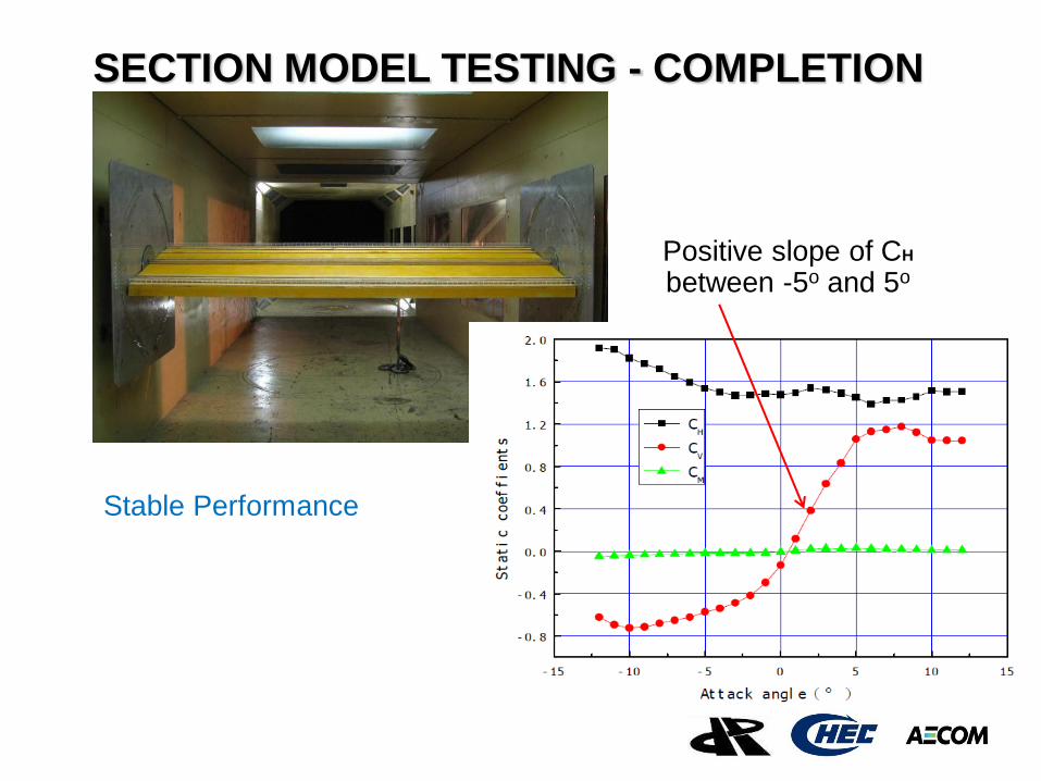
SECTION MODEL TESTING - COMPLETION
Positive slope of CH
between -5o and 5o
Stable Performance
Client logo
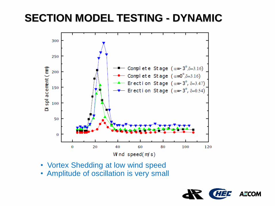
SECTION MODEL TESTING - DYNAMIC
• Vortex Shedding at low wind speed • Amplitude of oscillation is very small
Client logo
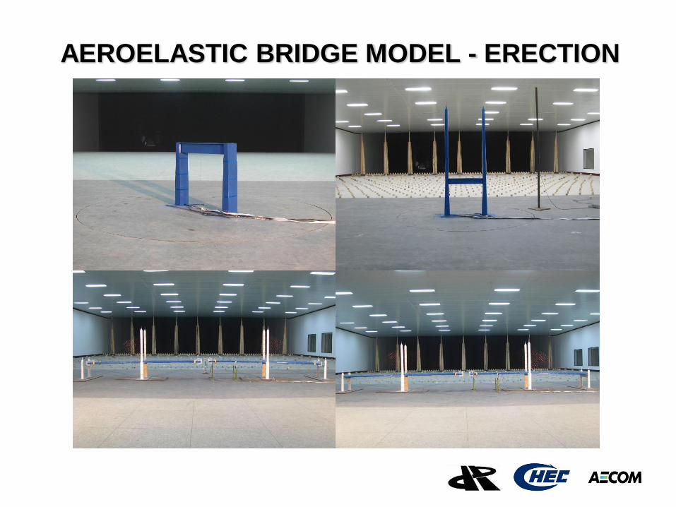
AEROELASTIC BRIDGE MODEL - ERECTION
Client logo
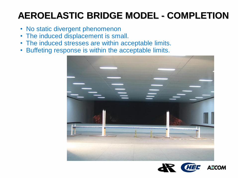
AEROELASTIC BRIDGE MODEL - COMPLETION
• No static divergent phenomenon • The induced displacement is small. • The induced stresses are within acceptable limits. • Buffeting response is within the acceptable limits.
Client logo
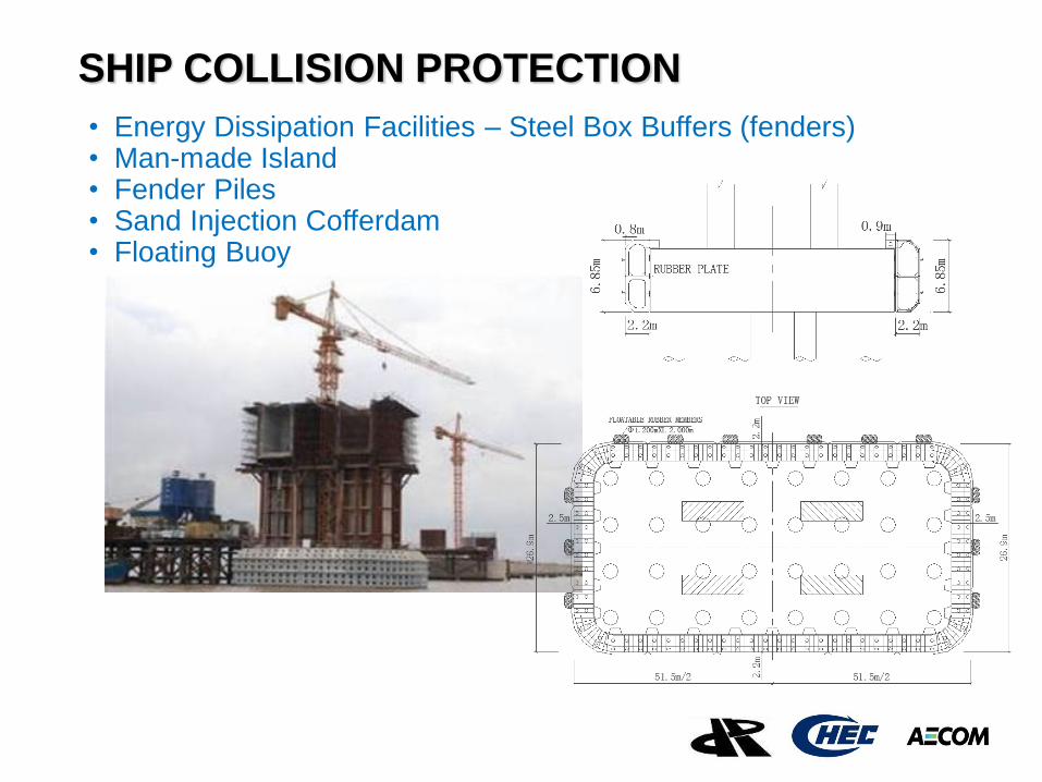
SHIP COLLISION PROTECTION
• Energy Dissipation Facilities – Steel Box Buffers (fenders) • Man-made Island • Fender Piles • Sand Injection Cofferdam • Floating Buoy
Client logo
HYDRAULICS STUDY
• Depth of Local Scour at Various Locations
• Wave and Current Loadings on Piles and Pile Caps
General Scour = 0.56m
Local Scour
Under Maximum Astronomical Tide,
4.23m at Pylons, 3.34m at Transition Piers, 3.33m at Approach Piers
Under Maximum Astronomical Tide and 120-year Wind,
6.18m at Pylons, 4.96m at Transition Piers, 5.03m at Approach Piers
Client logo
TSUNAMI AND LIQUEFACTION
Tsunami • Wave Generation and Propagation Hydrodynamics Model
• Calibration with tsunami event on 26 December 2004
• Maximum wave of 2.17m with an arrival time of 5 hours
Liquefaction
• probability < 5% for 0.06g ever recorded in Malaysia
• probability < 50% for 0.1g and Magnitude 7
Client logo
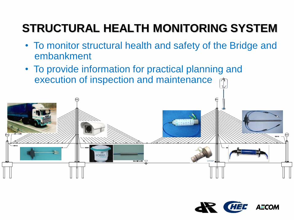
STRUCTURAL HEALTH MONITORING SYSTEM
• To monitor structural health and safety of the Bridge and embankment
• To provide information for practical planning and execution of inspection and maintenance
Client logo
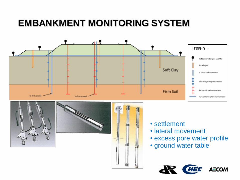
EMBANKMENT MONITORING SYSTEM
• settlement • lateral movement • excess pore water profile • ground water table
Client logo
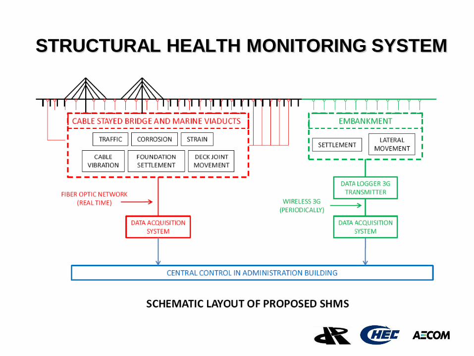
STRUCTURAL HEALTH MONITORING SYSTEM
Client logo
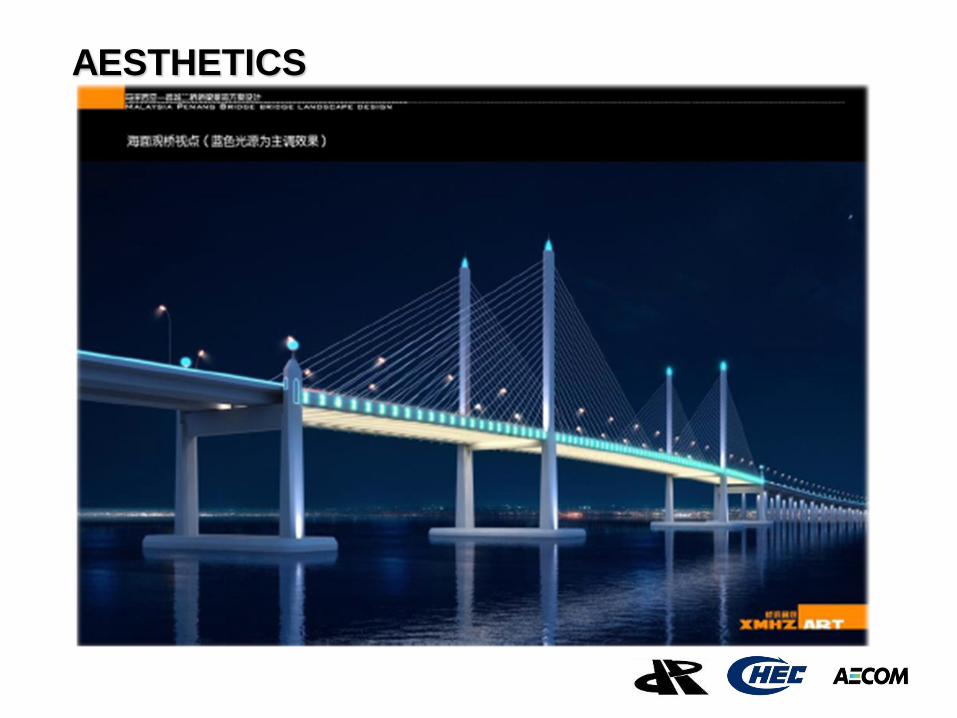
AESTHETICS
Client logo
THANK YOU