Embed Size (px)
Citation preview

The Design of Geosynthetic Final The Design of Geosynthetic Final Cover Systems Cover Systems & Future Alternatives& Future Alternatives
Pieter K. Scheer, P.E.Pieter K. Scheer, P.E.Richardson Smith Gardner & Associates, Inc.Richardson Smith Gardner & Associates, Inc.

Final Cover Cross SectionsFinal Cover Cross Sections(What Do Our Regulations Tell Us and What is Perhaps Typical?)(What Do Our Regulations Tell Us and What is Perhaps Typical?)

Cross Section of A Geosynthetic Cross Section of A Geosynthetic Final Cover SystemFinal Cover System
(Regulatory (Regulatory –– Subtitle D, NC, SC, VA)Subtitle D, NC, SC, VA)

Cross Section of A Geosynthetic Cross Section of A Geosynthetic Final Cover SystemFinal Cover System
(Regulatory (Regulatory -- Tennessee)Tennessee)

Cross Section of A Geosynthetic Cross Section of A Geosynthetic Final Cover SystemFinal Cover System
(Regulatory)(Regulatory)
Stipulated Regulatory Final Cover Systems Stipulated Regulatory Final Cover Systems Do Not Specifically Include a Drainage Do Not Specifically Include a Drainage Layer!!!Layer!!!–– A Drainage Layer is A Drainage Layer is EssentialEssential Except for Flatter Except for Flatter
Slopes (Say Below 10%)Slopes (Say Below 10%)Soil Barrier Component is of Questionable Soil Barrier Component is of Questionable Benefit Benefit –– Especially if k < 10Especially if k < 10--55 cm/seccm/sec

Cross Section of A Geosynthetic Cross Section of A Geosynthetic Final Cover SystemFinal Cover System
(Typical)(Typical)

Failures of Final Cover SystemsFailures of Final Cover Systems((UnderscoringUnderscoring the Importance of Proper Design)the Importance of Proper Design)

Failures of Final Cover SystemsFailures of Final Cover SystemsGreatly Exceed the Number of Failures of Landfill Liner Greatly Exceed the Number of Failures of Landfill Liner SystemsSystemsRatio of Failures is Perhaps 40 to 1!!!Ratio of Failures is Perhaps 40 to 1!!!Many of These Failures are Not Publicized Due to Legal Many of These Failures are Not Publicized Due to Legal Concerns (= Lack of Lessons Learned) Concerns (= Lack of Lessons Learned) Failures of Geosynthetic Final Cover Systems Occur Failures of Geosynthetic Final Cover Systems Occur Because of:Because of:
1.1. Excess Water Pressure in the Drainage Layer (Most Typical)Excess Water Pressure in the Drainage Layer (Most Typical)(Flow into drainage layer exceeds flow capacity of draina(Flow into drainage layer exceeds flow capacity of drainage layer ge layer leading to excess water pressure which uplifts the cover soil)leading to excess water pressure which uplifts the cover soil)
2. Veneer Stability (Weak Interface Relative to Slope Angle)2. Veneer Stability (Weak Interface Relative to Slope Angle)3. Landfill Gas Uplift3. Landfill Gas Uplift4. Erosion4. Erosion5. Combination of One or More of the Above (Typically Leads to #5. Combination of One or More of the Above (Typically Leads to #1)1)
Failures of Final Cover SystemsFailures of Final Cover Systems(Under(Under--Designed Drainage Layer)Designed Drainage Layer)

Failures of Final Cover SystemsFailures of Final Cover Systems(Landfill Gas Uplift)(Landfill Gas Uplift)

Failures of Final Cover SystemsFailures of Final Cover Systems(Landfill Gas Uplift)(Landfill Gas Uplift)

Failures of Final Cover SystemsFailures of Final Cover Systems(Erosion)(Erosion)

Failures of Final Cover SystemsFailures of Final Cover Systems(Erosion)(Erosion)

Failures of Final Cover SystemsFailures of Final Cover Systems(All of the Above!!!)(All of the Above!!!)

Failures of Final Cover SystemsFailures of Final Cover Systems(All of the Above!!!)(All of the Above!!!)

Design ElementsDesign Elements

Design ElementsDesign Elements
Design of Drainage LayerDesign of Drainage LayerGeotechnical Analyses (Veneer Stability & Geotechnical Analyses (Veneer Stability & Filter Design)Filter Design)Landfill Gas DesignLandfill Gas DesignSurface Water DesignSurface Water Design

Design of Drainage LayerDesign of Drainage Layer(Determining Required Flow Capacity)(Determining Required Flow Capacity)
The Flow Capacity of a Drainage Layer is Defined The Flow Capacity of a Drainage Layer is Defined in Terms of:in Terms of:–– Permeability and Thickness for Natural Drainage Media Permeability and Thickness for Natural Drainage Media
(Stone or Sand*); or(Stone or Sand*); or–– Transmissivity (Transmissivity (QQ = k x t) for Drainage Geocomposites= k x t) for Drainage Geocomposites**DONDON’’T USE SAND!!!T USE SAND!!!

Design of Drainage LayerDesign of Drainage Layer(Determining Required Flow Capacity)(Determining Required Flow Capacity)
FSQQ
OUT
IN
=

Design of Drainage LayerDesign of Drainage Layer(Determining (Determining QQININ))
DONDON’’T USE THE HELP MODEL to T USE THE HELP MODEL to Determine Determine QQININ!!!!!!!!–– Soong and Koerner (1997) Studied 8 Seepage Soong and Koerner (1997) Studied 8 Seepage
Related Slope Failures and Found That the Related Slope Failures and Found That the HELP Model UnderHELP Model Under--Predicted Predicted QQININ by Factors by Factors Ranging From 10 to 100.Ranging From 10 to 100.
Assume Infiltration Equal to Permeability of Assume Infiltration Equal to Permeability of Cover SoilCover Soil

Design of Drainage LayerDesign of Drainage Layer(Determining Required Transmissivity)(Determining Required Transmissivity)
θβ
ββ βreqd
dc n dc n dc nRF q Li RF q L RF q L= = =
sincos
sin tan
QQreqdreqd = required transmissivity of drainage geocomposite = required transmissivity of drainage geocomposite (m(m33/m/sec)/m/sec)
RFRFdcdc = drainage geocomposite reduction factor = drainage geocomposite reduction factor qqnn = fluid input rate/impingement rate (m/s)= fluid input rate/impingement rate (m/s)LL = flow length/drain spacing (horizontally projected) (m)= flow length/drain spacing (horizontally projected) (m)bb = slope angle of final cover (degrees)= slope angle of final cover (degrees)

Design of Drainage LayerDesign of Drainage Layer(Determining Required Transmissivity)(Determining Required Transmissivity)
Reduction Factor (Reduction Factor (RFRFdcdc) Accounts for:) Accounts for:–– IntrusionIntrusion–– CreepCreep–– CloggingClogging–– Overall Factor of SafetyOverall Factor of Safety
Richardson, Giroud, and Zhao Recommend Richardson, Giroud, and Zhao Recommend RFRFdcdc = 6= 6

Design of Drainage LayerDesign of Drainage Layer(Rules of Thumb)(Rules of Thumb)
Design for Maximum Drainage Length of Design for Maximum Drainage Length of 120 to 150 feet (Need to Add Drainage 120 to 150 feet (Need to Add Drainage Breaks)Breaks)Transmissivity of Drainage Geocomposite Transmissivity of Drainage Geocomposite should typically be on the order of 1 x 10should typically be on the order of 1 x 10--33
mm33/m/sec/m/sec–– Geonet Component of Drainage Geonet Component of Drainage
Geocomposites Will Typically Be At Least 0.25 Geocomposites Will Typically Be At Least 0.25 Inches Thick to Meet This Requirement Inches Thick to Meet This Requirement
–– Note That the Transmissivity of 1 foot of 1 x 10Note That the Transmissivity of 1 foot of 1 x 10--22
cm/sec Sand is Only 3 x 10cm/sec Sand is Only 3 x 10--55 mm33/m/sec!!!/m/sec!!!

Design of Drainage LayerDesign of Drainage Layer(Rules of Thumb)(Rules of Thumb)
Cover Soils More Permeable Than 1 x 10Cover Soils More Permeable Than 1 x 10--44
cm/sec Can Be Problematiccm/sec Can Be Problematic–– The Addition of Several Inches of Compost on The Addition of Several Inches of Compost on
Top of Cover Soils Can Greatly Reduce Top of Cover Soils Can Greatly Reduce Infiltration and Allow Desired Drainage LengthsInfiltration and Allow Desired Drainage Lengths
Assuming Cover Soils are Less Permeable Assuming Cover Soils are Less Permeable Than 1 x 10Than 1 x 10--55 cm/sec May Be Unrealistic cm/sec May Be Unrealistic and Lead to An Under Designed Drainage and Lead to An Under Designed Drainage LayerLayer
Design of Drainage LayerDesign of Drainage Layer(Specifying Transmissivity)(Specifying Transmissivity)
Always Require Conformance Tests!!!Always Require Conformance Tests!!!–– ManufacturerManufacturer’’s Data is Typically for Short Duration s Data is Typically for Short Duration
Between Steel PlatesBetween Steel PlatesWhen Specifying Transmissivity Include:When Specifying Transmissivity Include:–– Normal Load (Suggest 500 to 1,000 psf)Normal Load (Suggest 500 to 1,000 psf)–– Hydraulic Gradient (Use Maximum Slope Hydraulic Gradient (Use Maximum Slope –– 0.25 or 0.33)0.25 or 0.33)–– Minimum Seating Time of 24 Hours (Suggest 1 Test Minimum Seating Time of 24 Hours (Suggest 1 Test
Run to 100 Hours to Observe Effect of Creep from 24 to Run to 100 Hours to Observe Effect of Creep from 24 to 100 Hours) 100 Hours)
Boundary Conditions During Testing Must Boundary Conditions During Testing Must Approximate Actual Conditions (Suggest Using a Approximate Actual Conditions (Suggest Using a Sand Against Upper Surface of Geocomposite to Sand Against Upper Surface of Geocomposite to Account for Intrusion)Account for Intrusion)

Geotechnical AnalysesGeotechnical Analyses
Veneer Stability Veneer Stability –– Determining the Minimum Determining the Minimum Shear Strength Requirements to Meet:Shear Strength Requirements to Meet:–– FS (Static) FS (Static) >> 1.51.5–– FS (Seismic) FS (Seismic) >> 1.01.0
Filter Design Filter Design –– Evaluating Proposed Cover Evaluating Proposed Cover Soils and the Performance of the Upper Soils and the Performance of the Upper Geotextile of the Drainage Geocomposite as Geotextile of the Drainage Geocomposite as a Filtera Filter

Veneer StabilityVeneer Stability(Shear Strength Equation)(Shear Strength Equation)
tt = shear strength (psf)= shear strength (psf)ss = normal weight (psf)= normal weight (psf)FF = interface friction angle (degrees)= interface friction angle (degrees)c c = cohesion/adhesion (psf)= cohesion/adhesion (psf)
τ σ φ= +tan c

Veneer StabilityVeneer Stability(Kavazanjian Equation)(Kavazanjian Equation)
( ) ( )( )FS
cz
z dz
k
kc c
w c w
c cs
s=
+ −−⎡
⎣⎢⎢
⎤
⎦⎥⎥−
+
γ βφ
γγ
β φ
β
costan tan tan
tan
2 1
FS FS = factor of safety against veneer failure surface= factor of safety against veneer failure surfacec c = cohesion/adhesion along weakest (critical) interface= cohesion/adhesion along weakest (critical) interfaceggcc = unit weight of cover soil= unit weight of cover soilZZcc = depth of cover soil= depth of cover soilbb = slope angle of final cover (degrees)= slope angle of final cover (degrees)FF = interface friction angle along critical interface= interface friction angle along critical interfaceggww = unit weight of water= unit weight of waterddww = depth to water= depth to waterkkss = seismic coefficient (= 0 for static) (= peak grnd. accelerati= seismic coefficient (= 0 for static) (= peak grnd. acceleration for seismic)on for seismic)


Veneer StabilityVeneer Stability(Things to Keep In Mind)(Things to Keep In Mind)
The Addition of Layers in the Final Cover System The Addition of Layers in the Final Cover System Cross Section Increases Likelihood of Veneer Cross Section Increases Likelihood of Veneer Stability Issues.Stability Issues.Only Need to Specify Minimum Requirements for Only Need to Specify Minimum Requirements for Peak Shear StrengthPeak Shear Strength–– DonDon’’t Specify Different Values for Each Interface!!t Specify Different Values for Each Interface!!
In Order to Maximize the Shear Strength Against In Order to Maximize the Shear Strength Against the Geomembrane the Geomembrane –– Recommend Coextruded Recommend Coextruded Textured GM Because of Inherent Adhesion Textured GM Because of Inherent Adhesion (Velcro(Velcro®® -- Effect) Effect)

Filter DesignFilter Design
The Upper Geotextile of the Drainage The Upper Geotextile of the Drainage Geocomposite Must Perform as a FilterGeocomposite Must Perform as a FilterIn Filtration Design, Soils are Either In Filtration Design, Soils are Either ““StableStable””or or ““UnUn--StableStable””–– Stable Soils Perform an Internal Filtration Stable Soils Perform an Internal Filtration
Process Limiting the Migration of FinesProcess Limiting the Migration of Fines–– UnUn--Stable Soils Cannot Perform SelfStable Soils Cannot Perform Self--FiltrationFiltrationUnUn--Stable Soils Include GapStable Soils Include Gap--Graded, Graded, BroadBroad--Graded, and Highly Erodible SoilsGraded, and Highly Erodible Soils

Filter DesignFilter Design

Filter DesignFilter DesignFor Final Covers Soil Retention is KeyFor Final Covers Soil Retention is KeySeveral Methods Can be Used to Evaluate the Required Several Methods Can be Used to Evaluate the Required AOS of the Filter Geotextile Based on Soil PropertiesAOS of the Filter Geotextile Based on Soil PropertiesLuettich Method Luettich Method (from Mirafi):(from Mirafi):

Landfill Gas DesignLandfill Gas Design
Landfill Gas Must be either Actively Landfill Gas Must be either Actively Collected or Passively Vented to Minimize Collected or Passively Vented to Minimize Uplift Potential on GeomembraneUplift Potential on GeomembraneIf an Active Collection System is InIf an Active Collection System is In--Place Place Consider BackConsider Back--Up Passive Measures if Up Passive Measures if System Goes DownSystem Goes Down–– May Have to Convince Air Quality RegulatorsMay Have to Convince Air Quality Regulators

Landfill Gas DesignLandfill Gas Design(Accounting for Uplift Pressure)(Accounting for Uplift Pressure)
( ) ( )( )FS
cz
z dz
k
kc c
w c w
c cs
s=
+ −−⎡
⎣⎢⎢
⎤
⎦⎥⎥−
+
γ βφ
γγ
β φ
β
costan tan tan
tan
2 1
Revisiting the Veneer Stability Equation:Revisiting the Veneer Stability Equation:
–– uu = Equivalent Pressure Acting on Bottom of GM= Equivalent Pressure Acting on Bottom of GMDesigning for More Than a Pressure of 6Designing for More Than a Pressure of 6--inches Water inches Water Column (31 psf) Can Be Problematic Column (31 psf) Can Be Problematic –– Leading to Interface Leading to Interface Shear Strength Requirements That May Exceed Shear Strength Requirements That May Exceed Achievable ValuesAchievable Values
( )u z dw c w= −γ

Landfill Gas DesignLandfill Gas Design(Passive Back(Passive Back--Up)Up)

Surface Water DesignSurface Water DesignDONDON’’T ASSUME SHEET FLOW Over Long T ASSUME SHEET FLOW Over Long Distances!!! (say > 200 feet)Distances!!! (say > 200 feet)The Key Component of Surface Water Design is The Key Component of Surface Water Design is Limiting the Slope Length by Adding Drainage Limiting the Slope Length by Adding Drainage BreaksBreaks–– Fortunately, Drainage Breaks for Surface Water Fortunately, Drainage Breaks for Surface Water
Can/Should Be Aligned With Drainage Breaks for the Can/Should Be Aligned With Drainage Breaks for the Drainage Layer Drainage Layer
Drainage Breaks Can Be Accomplished with:Drainage Breaks Can Be Accomplished with:–– Diversion BermsDiversion Berms–– ““Rain GuttersRain Gutters””–– TackTack--On BermsOn Berms–– Benches (At Expense of Airspace Benches (At Expense of Airspace –– But Sometimes But Sometimes
Necessary)Necessary)

Surface Water DesignSurface Water Design(Drainage Breaks)(Drainage Breaks)

Surface Water DesignSurface Water Design(Rain Gutters)(Rain Gutters)

Surface Water DesignSurface Water Design(Tack On Berms)(Tack On Berms)

Surface Water DesignSurface Water Design(Rain Gutters)(Rain Gutters)
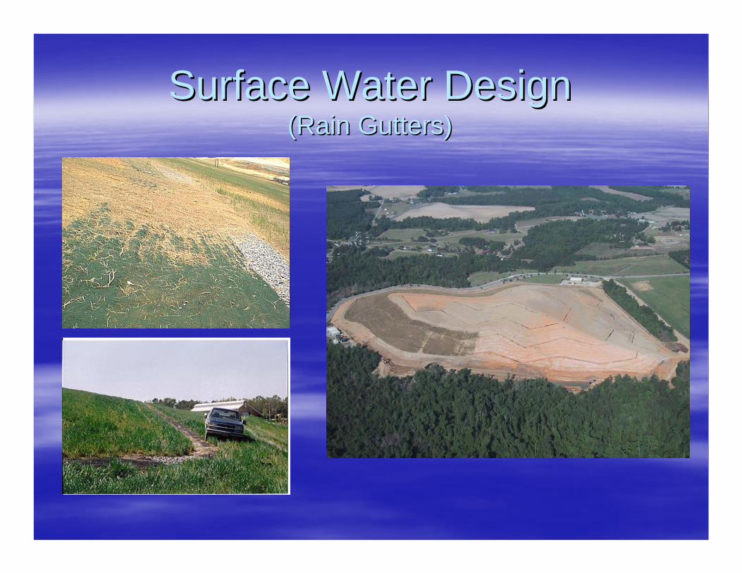
Surface Water DesignSurface Water Design(Rain Gutters)(Rain Gutters)

Future AlternativesFuture Alternatives

Future AlternativesFuture Alternatives
Why Alternatives? Why Alternatives? ---- Because ThereBecause There’’s a Lot That s a Lot That Can Go Wrong with Geosynthetic Final Covers!!! Can Go Wrong with Geosynthetic Final Covers!!! (Not Just Design But Maintenance Too!!!)(Not Just Design But Maintenance Too!!!)Future (Limited Current Use) Alternatives Include:Future (Limited Current Use) Alternatives Include:–– Advanced GeosyntheticsAdvanced Geosynthetics–– Exposed Geomembrane CoversExposed Geomembrane Covers–– ReRe--Evaluating Soil and Phyto CoversEvaluating Soil and Phyto Covers–– Other Options for Drier Climates (Example Other Options for Drier Climates (Example -- Capillary Capillary
Barrier)Barrier)

Future AlternativesFuture Alternatives(Advanced Geosynthetics)(Advanced Geosynthetics)
Combined geomembrane and geocompositeCombined geomembrane and geocomposite-- High Flow Capacity Drain On TopHigh Flow Capacity Drain On Top-- Textured Bottom SurfaceTextured Bottom Surface-- Limits Number of Interfaces if Geotextile is Bonded to SurfaceLimits Number of Interfaces if Geotextile is Bonded to Surface-- Still Too Many Limitations (Panel Size, Etc.)Still Too Many Limitations (Panel Size, Etc.)

Future AlternativesFuture Alternatives(Exposed Geomembrane Covers)(Exposed Geomembrane Covers)
LongLong--Term Interim Approach (Final???)Term Interim Approach (Final???)Maybe Best Suited for Bioreactors/Recirculation Landfills Maybe Best Suited for Bioreactors/Recirculation Landfills Where Settlement May be SignificantWhere Settlement May be SignificantDesign Issues:Design Issues:–– Wind & LFG UpliftWind & LFG Uplift–– Stormwater Runoff (Runoff Coefficient Near 1)Stormwater Runoff (Runoff Coefficient Near 1)–– UV ExposureUV Exposure–– MaintenanceMaintenance
Future AlternativesFuture Alternatives(Soil and Phyto Covers)(Soil and Phyto Covers)
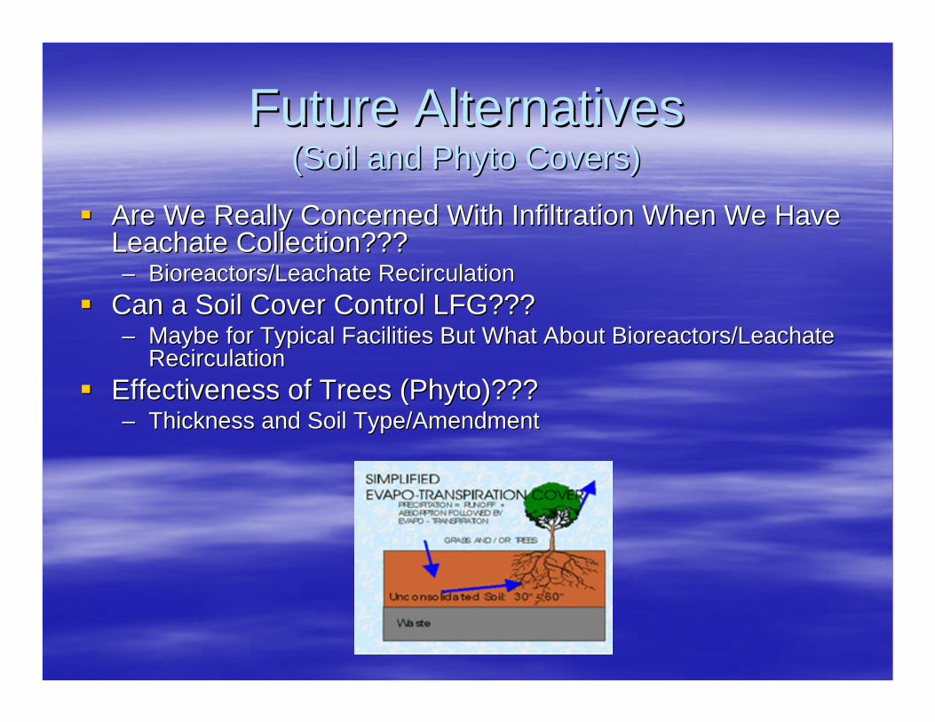
Are We Really Concerned With Infiltration When We Have Are We Really Concerned With Infiltration When We Have Leachate Collection???Leachate Collection???–– Bioreactors/Leachate RecirculationBioreactors/Leachate Recirculation
Can a Soil Cover Control LFG???Can a Soil Cover Control LFG???–– Maybe for Typical Facilities But What About Bioreactors/LeachateMaybe for Typical Facilities But What About Bioreactors/Leachate
RecirculationRecirculationEffectiveness of Trees (Phyto)???Effectiveness of Trees (Phyto)???–– Thickness and Soil Type/AmendmentThickness and Soil Type/Amendment

For More Information:For More Information:Pieter K. Scheer, P.E.Pieter K. Scheer, P.E.
Richardson Smith Gardner & Associates, Inc.Richardson Smith Gardner & Associates, Inc.14 N. Boylan Avenue14 N. Boylan AvenueRaleigh, NC 27603Raleigh, NC 27603
(919) 828(919) 828--05770577www.rsgengineers.comwww.rsgengineers.com
[email protected]@rsgengineers.com