Embed Size (px)
Citation preview
The Design of DESY IV -- Booster Upgrade for PETRA IV 2nd Topical Workshop on Injection and Injection systems (RULε series)
1st – 3rd April 2019
Hung-Chun Chao 1st April 2019 Villigen PSI, Switzerland

Page 2
0. Outline
1. Introduction
2. Lattice
3. Layout
4. Orbit Correction
5. Magnets
6. Ramping Dynamics
7. Injections and Extraction
8. Beam Recycle [optional]
9. Summary
| The Design of DESY IV | Hung-Chun Chao,1/4/2019

Page 3
1. Introduction • PETRA IV
− Inherent PETRA tunnel (2304m w/ 8 arcs and 4+4 “long” straights)
− 8 * Hybrid 7BA in each arc, emittance = 17 pm-rad (6 GeV), on-axis swap out injection
− 200 mA 80 bunch trains for brightness mode, 80 mA 80 bunches for timing mode (4.8E10)
• Current injector complex
− Thermionic DC gun -> Linac II (450 MeV) -> PIA -> DESY II (6GeV)
• Injector considerations
− Intensity N > 5.4E10, emittance ε < 30nm-rad (DESY II: ε = 350 nm-rad)
− Obey geometric constraints, Test beam facility, project timeline schedule, timing scheme
− Beam uniformity, injection efficiency, cost, recycle beam(optional), etc
• Options for injector upgrade
− Full energy full intensity Linac (6 GeV)
− Linac II -> PIA -> DESY II booster -> Accumulator in PETRA tunnel (expensive)
− Linac II -> DESY II accumulator -> DESY IV booster (low efficiency)
− Linac II -> PIA -> DESY II booster -> DESY IV accumulator (complicate)
− Linac II -> PIA -> DESY IV + beam stacking (cheapest)
− Linac II (700 MeV) -> PIA II -> DESY IV
Linac II (700 MeV) -> DESY IV (upgrade photocathode RF gun)
− Laser plasma wakefield accelerator (under discussion)
| The Design of DESY IV | Hung-Chun Chao,1/4/2019

Page 4
2. Lattice
| The Design of DESY IV | Hung-Chun Chao,1/4/2019
Linear and non-linear properties
Parameters Values
Periodicity 6
Circumference 316.8 m
Harmonic Number 528*
Straight Length 2.745 / 0.935 / 1.165 m
Working Tune 18.25 / 10.37
Natural Chromaticity -22.2 / -19.4
Damping Partition -0.36
Momentum Compaction 3.3 E-3
Beam Energy 6 GeV 700 MeV
Energy Loss per Turn 4.04 MeV 0.748 KeV
Equilibrium Emittance 19.3 nm-rad 0.261 nm-rad
Equilibrium Energy Spread 1.12 E-3 1.23 E-4
Horizontal Damping Time 2.29 ms 1.44 s
Vertical Damping Time 3.14 ms 1.98 s
Longitudinal Damping Time 1.92 ms 1.12 s
DA without errors (4D tracking)
Dynamic tuning
* Use 500 MHz RF, hP4/hD4=80/11
37 cm gap
Insertion Section

Page 5
3. Layout
• The abandoned DESY III will be removed.
• DESY IV shares the tunnel with DESY II.
• It goes counter-clockwise. (opposite to DESY II)
• 6-fold symmetries: 3 insertion sections are for cavities and 3 for injections/extraction
• Insertion #1 has two fast bumpers and one septum installed for the low energy off-axis injection.
• Insertion #2, 3, 5 house 5 RF modules (one spare) and 1 harmonic cavity (optional).
• Insertion #4 has two bumpers, one fast kicker, and one or more septums for the extraction.
• Insertion #6 has some elements for the injection of the recycled beam.
• Insertion #4 and 6 are geometrically symmetric w.r.t transport lines.
• Test beam facility beamlines are extracted (from BD) around 3 o’clock position.
| The Design of DESY IV | Hung-Chun Chao,1/4/2019
Six insertion sections Test Beam Facility

Page 6
4. Orbit Correction Schemes
| The Design of DESY IV | Hung-Chun Chao,1/4/2019
Different configurations
Trim coil
• Error sources • Alignment errors:
−Δx = 0.1 mm, Δy = 0.1 mm −Δφ (rolling angle) = 0.2 mrad
• Field errors: − Dipole: 0.02%, Quadrupole: 0.2%
• Beam stay clear (BSC=3σ beam size + max COD) without orbit correction is estimated < 15 mm at insertion sections and < 12 mm at FODO-arcs
• Correctors ramp with energy • Configuration C5 is efficient. (max str < 0.6 mrad)
100 random machines

Page 7
5. Magnets
Magnet BD BF BM QM1 QM2 S1 S2
L (m) 1.75 1.85 1.00 0.3 0.3 0.2 0.2
B0 (T)* 0.86 0.35 0.90
K0 (m-1) 0.043 0.0175 0.045
K1 (m-2) -0.44 0.49 -1.84 1.66
K2 (m-3) -4.78 2.89 3** 3**
# Elements 54 60 6 12 12 12 12
| The Design of DESY IV | Hung-Chun Chao,1/4/2019
Combined function magnets
BF
• BM is a C-type pure function dipole for the consideration of beam injection/extraction. • Programmable independent power supplies for quad trim coils and sextupoles for
dynamic tunning • The ideal pole faces follows the equi-potential lines equation Φ 𝑥𝑥,𝑦𝑦 = Φ(0, ±ℎ), • where the 2D scalar potential is Φ 𝑥𝑥,𝑦𝑦 = 𝐾𝐾0𝑦𝑦 + 𝐾𝐾1𝑥𝑥𝑦𝑦 + 𝐾𝐾2
63𝑥𝑥2𝑦𝑦 − 𝑦𝑦3 .
• Defining 𝑝𝑝 ≡ 2𝐾𝐾0𝐾𝐾2
+ 2𝐾𝐾1𝐾𝐾2𝑥𝑥 + 𝑥𝑥2 and 𝑞𝑞 ≡ ℎ3
2− 3𝐾𝐾0
𝐾𝐾2ℎ, around 𝑥𝑥 = 0,
− 𝑦𝑦 = ±2 𝑝𝑝 cos (13
cos −1 𝑝𝑝−3/2𝑞𝑞 − 2𝜋𝜋3
) for BF
− 𝑦𝑦 = ±2 𝑝𝑝 sinh(13
sinh −1(|𝑝𝑝|−3/2𝑞𝑞)) for BD • The actual pole faces need to be tweaked. • Use H-type magnets instead of C-type
BD
half gap h > 15 mm good field region = beampipe radius r > 12 mm
* Estimated at 6 GeV ** Maximal sextupole strengths normalized at 6 GeV

Page 8
6. Ramping Dynamics
• Repetition rate is 2~5 Hz (default: 2 Hz)
• 500 MHz 5-cell PETRA cavity is used.
• Energy ramps from 0.7 MeV to 6 GeV sinusoidally.
• Initial RF voltage has to be large enough to accommodate 3 successive bunches from LINAC (Vi>1.8 MV)
• Final RF voltage has to provides sufficient longitudinal quantum lifetime (Vf >5.5 MV).
| The Design of DESY IV | Hung-Chun Chao,1/4/2019
Repetition rate = 2~5 Hz • Ramping curve (2 Hz)
• Damping of the emittance and energy spread
• Change of energy acceptance, synchrotron tune, synchronous phase
• Eddy currents induced sextupole fields and the chromaticity shifts
• Required additional sextupole strengths to compensate chromaticity shifts
Page 9
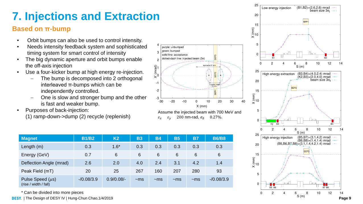
7. Injections and Extraction
Magnet B1/B2 K2 B3 B4 B5 B7 B6/B8
Length (m) 0.3 1.6* 0.3 0.3 0.3 0.3 0.3
Energy (GeV) 0.7 6 6 6 6 6 6
Deflection Angle (mrad) 2.6 2.0 4.0 2.4 3.1 4.2 1.4
Peak Field (mT) 20 25 267 160 207 280 93
Pulse Speed (𝜇𝜇s) (rise / width / fall)
-/0.08/3.9 0.9/0.08/- ~ms ~ms ~ms ~ms -/0.08/3.9
| The Design of DESY IV | Hung-Chun Chao,1/4/2019
Based on π-bump • Orbit bumps can also be used to control intensity. • Needs intensity feedback system and sophisticated
timing system for smart control of intensity • The big dynamic aperture and orbit bumps enable
the off-axis injection • Use a four-kicker bump at high energy re-injection.
− The bump is decomposed into 2 orthogonal interleaved π-bumps which can be independently controlled.
− One is slow and stronger bump and the other is fast and weaker bump.
• Purposes of back-injection: (1) ramp-down->dump (2) recycle (replenish)
* Can be divided into more pieces
Assume the injected beam with 700 MeV and 𝜀𝜀𝑥𝑥 = 𝜀𝜀𝑦𝑦 = 200 nm-rad, 𝜎𝜎𝛿𝛿 = 0.27%.

Page 10
8. Beam Recycle (Optional)
• Other than a new RF photocathode gun, possible alternative options for high intensity beam preparation are proposed. Two of them recycle the swapped-out beam into the booster.
1. [Recycle beam first + top up at low energy]
• Reverse the high energy extraction as high energy injection
• The recycled bunch can be replenished by fresh bunch at low energy by the method of transversely beam stacking with varying energy.
(1) Take the swapped-out beam as the first beam
(2) Ramp the beam energy down and fetch a fresh bunch in low energy injection section.
(3) Raise the energy until the two bunches are fully damped and merged.
• This method also provides a way to accumulate the beam in the booster. In such case step (1) is skipped and step (2) and (3) are repeated multiple times until the desired intensity is reached.
• Concerns about particle loss during ramping. Instability is more significant at low energy.
2. [HEPS option, pour recycled beam after]
• Firstly inject fresh bunches from LINAC and accelerate to 6 GeV, then pour the swapped-out beam to be merged with the existing beam.
• Use a four-kicker bump for injection. This hardware configuration also works for the first option.
• Need more precise orbit control
3. [Phase space painting][No recycle]
• Accelerate two bunches painted at low energy [NSLS2, PRSTAB 14, 020101]
| The Design of DESY IV | Hung-Chun Chao,1/4/2019
Different ways to prepare high intensity beam
Page 11
9. Summary
| The Design of DESY IV | Hung-Chun Chao,1/4/2019
Choose the feasible, simplest option for injector complex upgrade
• New booster DESY IV with upgraded RF gun/LINAC II and without accumulator PIA
DESY IV features
• Tight ring fit into DESY tunnel
• Small emittance by combined function magnets
• A section dedicated for recycled beam injection
• Independent programmable power supplies for trim coils in quads and sextupoles for dynamic tuning during ramping
• π-bumps for injections and extraction
• Simplified orbit corrector scheme
• Ramping dynamics and beam recycle options for high intensity beam preparation are discussed.
• DESY IV is the complement of PETRA IV.
To-be-complete
• Magnet design is underway. (pulsed/ramping)
• Errors tolerance study
• Impedance and instability study (Impedance budget for TMCI: Zt,eff < 0.6 MΩ/m [Y.-C.Chae])
• Intensity control and timing systems development
• Thanks everyone!