Embed Size (px)
Citation preview

Earth Structures and Retention Conference 2014 1
THE DESIGN OF A PILED THROUGH MASS GRAVITY STONE®
STRONG WALL FOR CANTERBURY STREET, CHRISTCHURCH
INFRASTRUCTURE REBUILD PROJECT
Barry Wai-Choo Kok1, Jeroen Berends2 and Martin Silec3
1&2Principal Geotechnical Engineer,
Geoinventions Consulting Services, Brisbane, Queensland, Australia. 3Managing Director,
Concrib Pty Ltd, Brisbane, Queensland, Australia.
ABSTRACT
Several retaining walls exhibited structural damage and collapse following the Christchurch earthquake in
February 2011. These retaining walls had to be redesigned and rebuilt using more resilient retaining wall systems
to withstand the peak ground acceleration of 0.52g. A 3.8m high mass gravity Stone® Strong retaining wall was
designed and constructed in Lyttelton, south of Christchurch. The formation is known as the Lyttelton Volcanic
Group which consists of a thick mantle of Canterbury Loess (windblown glacial silt). The Stone® Strong retaining
wall system consists of large modular precast hollow blocks which allowed 550mm diameter auger piles to be
installed through the block cavity to provide additional lateral resistance. This paper describes the design
verification process using finite element analysis to assess the stability and serviceability of the critical wall
sections under seismic condition provided by the principal designer.
1 INTRODUCTION
1.1 PROJECT BRIEF
Following the earthquake in February 2011, several retaining structures were damaged or had collapsed due to
ground motion associated with earthquakes that occurred in the Lyttelton area. Stronger Christchurch
Infrastructure Rebuild Team (SCIRT) were engaged in rebuilding these walls to meet current building code and
New Zealand standards, which includes the revised seismic hazard factor for Christchurch. This technical paper
describes the design verification process for the RW05 retaining structure on Canterbury Street.
An alternative Stone® Strong retaining wall system was adopted for RW05 walls, replacing the previously
specified Fulton Hogan concrete blocks. The alternative system incorporated piled foundations and tieback anchor
forces to provide supplementary wall capacity where gravity wall performances are insufficient.
Figure 1: Location map and Stone® Strong retaining structure location

Earth Structures and Retention Conference 2014 2
1.2 STONE® STRONG SYSTEM
The Stone® Strong system was first introduced in the United States of America in 2001 and was launched in New
Zealand in 2007. The first wall built in Australia was constructed by Concrib Pty Ltd in 2011, for the Gold Coast
City Council. The Stone® Strong System consists of large modular precast hollow blocks suitable for gravity
retaining structures up to 5.0m and RSS walls in excess of 15.0m. The standard 24SF block has a plain straight or
chiselled granite face area of 2.24m² and a mass of 2722kg. The smaller 6SF block has a 0.56m² face area and a
mass of 680kg. Each block is manufactured using a minimum concrete strength of 40MPa at 28 days and are
internally backfilled with aggregate to provide additional retaining wall mass.
Figure 2: Typical Stone® Strong blocks dimension
2 PROJECT DESIGN METHODOLOGY
2.1 REGIONAL AND LOCAL GEOLOGY
The regional geology in the Lyttelton area comprises of loess deposits typically 0.5m to 5.0m thick. However,
deposits up to 20.0m thick may be found at the base of steep slopes. Loess is a silty or loamy material deposited
predominately by wind. The loess deposits are underlain by the Lyttelton Volcanic Group, which typically consists
of basalt and pyroclastic deposits.
During the site reconnaissance, exposed loess was described generally as fine-grained deposits with discontinuous
seams of more granular material. The material exhibited low plasticity and was estimated to be firm to hard in
consistency. In general, the loess deposits are described by McDowell (1989) as silt with a lesser amount of clay-
sized particles (10% to 19%). Atterberg limits tests on samples collected indicated that Plasticity Index (PI) ranged
from 4% to 10%, with the higher range containing more clay. Strength tests performed on collected samples
included unconsolidated, undrained (UU) triaxial tests. Plot interpreted results from the UU tests were utilised for
the estimation of cohesion and internal friction angle for loess. Based on the plotted results in Figure 3, a lower-
bound trend line considering a cohesion intercept of 25kPa and an internal angle of friction of 30 degrees was
adopted.
In response to the observation of the site photos illustrated below, loess slopes are self-supporting, and near
vertical loess slopes several metres high exist throughout the Lyttelton area. This exposed loess has demonstrated
apparent cohesion in excess of 100kPa and internal friction angle above 30 degrees.
Figure 3: Triaxial test results and typical self-supported loess slopes
Earth Structures and Retention Conference 2014 3
2.2 DESIGN REQUIREMENTS AND ADOPTED DESIGN PARAMETERS
The design life of the Stone® Strong gravity structure is 100 years and the structure was classified as a Category
B wall which directly supports a road. Throughout the design life, full detailed inspections shall be completed for
all earthquakes with a Peak Ground Acceleration (PGA) exceeding 0.2g or where a change in horizontal alignment
of the wall exceeds 50mm.
Prior to stability analysis, representative properties must be assigned to each material used in the Stone® Strong
structure. Each material was characterised by the friction angle, cohesion and representative bulk unit weight as
shown in the Table 1 below
Material Properties Block Infill
Aggregate
Loess
Retained Fill
Foundation
Soil
Controlled
Engineered Fill
Angle of internal friction, ɸ’ (deg) 35 30 30 34
Bulk unit weight of soil, γ (kN/m3) 20 19 19 20
Cohesion, c’ (kPa) 0 25 25 0
Table 1: Soil properties adopted in design
The New Zealand Geotechnical Society, Inc. (NZGS, 2010) and the Structural Engineering Society of Canterbury
(SESOC) recommended a seismic design PGA value of 0.52g for the gravity structure on the Canterbury Street.
The Canterbury Loess was assessed and considered not to be susceptible to liquefaction.
A 12kPa uniformly distributed load was adopted in the stability analysis to accommodate for the heaviest loading
condition during construction. Groundwater was not anticipated to occur at the site and flood levels were located
well below the toe of the Stone® Strong structure. Therefore, fully saturated conditions were not considered in the
design model.
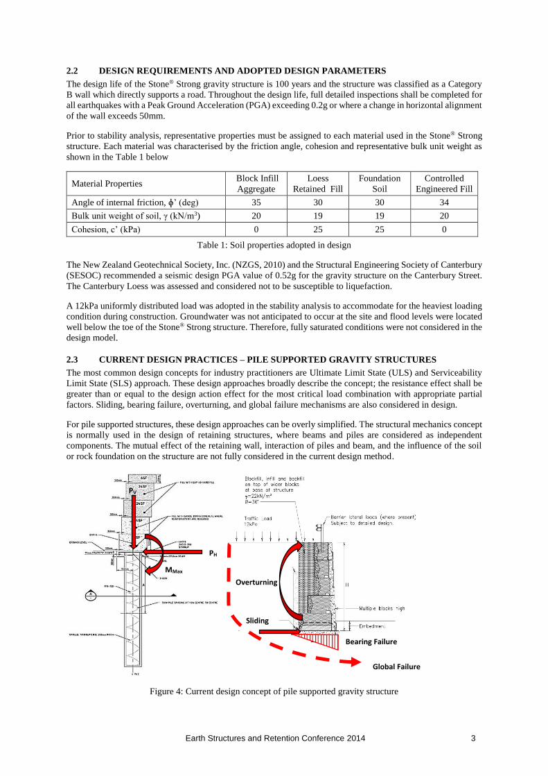
2.3 CURRENT DESIGN PRACTICES – PILE SUPPORTED GRAVITY STRUCTURES
The most common design concepts for industry practitioners are Ultimate Limit State (ULS) and Serviceability
Limit State (SLS) approach. These design approaches broadly describe the concept; the resistance effect shall be
greater than or equal to the design action effect for the most critical load combination with appropriate partial
factors. Sliding, bearing failure, overturning, and global failure mechanisms are also considered in design.
For pile supported structures, these design approaches can be overly simplified. The structural mechanics concept
is normally used in the design of retaining structures, where beams and piles are considered as independent
components. The mutual effect of the retaining wall, interaction of piles and beam, and the influence of the soil
or rock foundation on the structure are not fully considered in the current design method.
Figure 4: Current design concept of pile supported gravity structure
PV
PH
MMax
Sliding
Overturning
Bearing Failure
Global Failure

Earth Structures and Retention Conference 2014 4
2.4 STRESS-BASED DESIGN APPROACH – LIMIT EQUILIBRIUM ANALYSIS
Seismic design of gravity structures is most commonly performed by using the pseudo-static approach which has
all the limitations of stress-based design methods applied to earthquake engineering. The computed Factor of
Safety (FOS) is purely conventional. The pseudo-static method is inherently incompatible with the strain-based
design philosophy, due to its inability to quantify the magnitude of wall displacement.
As described in the project design document (2012), pseudo-static sliding stability analysis was performed on the
critical section of the structures using the procedure in FHWA (2003). The pseudo-static loads are defined as the
seismically-induced inertial forces within the soil block of the structures and the dynamic thrust (PAE) of the
retained material behind the soil block.
During the initial assessments, global slope stability analyses of the critical cross sections of the structures were
carried out using the commercial software Slope/W 2007, which is based on a two-dimensional limiting
equilibrium method. FOS against failure were computed using the Morgenstern-Price method of analysis. The
particular procedure employed, generates circular-shaped failure surfaces between specified coordinate limits. Strength and unit weight parameters adopted in the stability analyses are tabulated in Table 1.
Structure Location Analysis Computed FOS Required FOS
RW05 (132C)
CH80+000
2H:1V Retained Slope
4.0m Retained Height
3.8m Wall Height
Static – Short-Term
(During Construction) 1.92 1.20
Static – Long-Term 4.96 1.50
Pseudo-static Approach 1.72 1.25
*Extracted from SCIRT Detailed Design Report 10394 (2012)
Table 2: Computed FOS vs Required FOS
2.5 STRAIN-BASED DESIGN APPROACH – FINITE ELEMENT ANALYSIS
For gravity structures, the most significant performance indicator is the after quake, long term displacement or
deflection of the structure. During an earthquake, temporary loss of equilibrium of the gravity structures that fails
by sliding may be acceptable, if within the tolerance. This lead to the concept of “failure” becomes strictly
connected to the concept of “allowable displacement or deflection”. Hence, the stress-based design approach –
limit equilibrium under seismic actions is not mandatory in governing the design. The design focus lies in
calculating the permanent displacement or deflection of the structures. Strain-based design focuses on the
expected structures displacement or deflection, thus providing a measure of the expected damage.
The maximum displacement for critical cross section of the structures was computed using the commercial finite
element software PLAXIS. Based on analysis of the anticipated loads, a maximum horizontal displacement of
29mm was computed for the structures. By comparison, the requirements of the Christchurch City Council
Retaining Wall Design Guide (Beca, 2011) indicate that for collector roads (Canterbury Street) displacements
must be less than 100mm for rigid walls and 200mm for flexible walls. In summary, the results of the analyses
indicate that the walls will not exceed maximum displacements or collapse due to ground motions during
earthquake.

Earth Structures and Retention Conference 2014 5
Figure 5: Deformed mesh of finite element model for the pile supported structure
Figure 6: Total displacement contour of finite element model for the pile supported structure

Earth Structures and Retention Conference 2014 6
Figure 7: Residual displacements at various positions of the pile supported structure during earthquake
3 CONSTRUCTION METHODOLOGY
Removal of the rotated or collapsed walls was limited to 10.0m increments. The existing backfill material was
excavated until the natural loess soils were exposed. Steeper temporary excavations were stabilised by means of
temporary soils nails 10.0m long installed at an angle of 15 degrees and reinforced shotcrete.
Figure 6: Reconstruction process of the collapsed wall and temporary shotcrete support
The natural loess foundation soil was compacted prior to casting a 200mm thick 20MPa concrete footing beneath
the first row of Stone® Strong blocks.
A series of 550mm diameter holes were drilled at 1.22m c/c through the Stone® Strong internal block voids.
Circular reinforcement cages were installed in the predrilled holes. The cages consisted of eight 32mm steel
reinforcement bars with a yield strength of fy = 500MPa. Piles were embedded 3.0m and 4.0m below the concrete
foundation for wall heights of 2.5m and 4.0m respectively. Reinforcement cage lengths varied between 3.5m and
6.3m respectively. Voids between the pile cage and Stone® Strong block were concrete filled ensuring a minimum
cover of 75mm.
Figure 7: Construction process of the pile supported gravity structure

Earth Structures and Retention Conference 2014 7
Subsequent blocks were backfilled with 20mm gap graded aggregate to provide additional retaining structure
mass and provide additional drainage at the front of the structure. A 160mm diameter subsoil drain and 250mm
thick drainage layer was installed behind the Stone® Strong blocks to dissipate any pore water pressures.
Although the original requirement was to relocate the overhead power/communications pole to a minimum of
2.0m away from the back of the structure, the pole was incorporated within the Stone® Strong wall by modifying
the back of the block and placing the Stone® Strong blocks around the pole. This eliminated the necessity for the
poles to be removed which would cause construction delays. Special tapered capping units were manufactured to
follow the specific road gradient and allow for easy installation of guardrails.
4 RECOMMENDATIONS AND CONCLUSIONS
An overview of the project upon completion provides the following recommendations and conclusions:
A. The assessment of the long-term displacement or deflection of pile supported gravity structure subjected
to earthquake loading is a difficult problem to solve, even when using advanced numerical modelling.
Validation based on real-case histories or experimental verification by means of shaking table or seismic
centrifuge testing, would be essential to endorse the outcome of numerical simulations.
B. The stress-based limit equilibrium approach with pseudo-static method is inherently incompatible with
the strain-based design philosophy and the computed FOS is purely oversimplified in seismic design.
C. The innovative Stone® Strong system allows for piles to be drilled and installed after block placement
through the internal void spaces.
D. Blocks can be stacked to a height of 2.76m prior to backfilling, which speeds up the construction process
and can be easily modified to accommodate existing services.
Figure 8: The completed Stone® Strong pile supported gravity structure
5 ACKNOWLEDGEMENTS
The authors of this paper would like to acknowledge and thank Stronger Christchurch Infrastructure Rebuild
Team (SCIRT), Fraser Geologics, Stone® Strong Systems and Concrib Pty Ltd for their assistance and kind
permission to publish this paper. We look forward to future collaboration with many of these individuals in our
effort to implement innovative and useful infrastructure related technology.

Earth Structures and Retention Conference 2014 8
6 REFERENCES
Federal Highway Works Administration (FHWA), Geotechnical Earthquake Engineering Reference Manual,
Publication No. FHWA HI-99-012, 1998.
Federal Highway Works Administration (FHWA), Geotechnical Engineering Circular N0.4, Ground Anchors
and Anchored Systems, Publication No. FHWA IF-99-015, 2003.
GeoSlope International, SLOPE/W Computer Program, Calgary, Alberta, Canada, 2007
PLAXIS, Finite Element Computer Program, Delft, The Netherlands, 2007
Qun Chen, Li Wan, Changrong He and Zihui, Load Transfer And Stress In A Piled Gravity Retaining Wall,
ACTA Geotechnica Slovenica Conference, 2010
Corigliano M., Lai C.G., Pasquali R, Displacement-based seismic design of gravity walls using double-support
excitation, 8th International Conference on Structural Dynamics, Eurodyn, 2011
Beca Infrastructure Ltd (Beca), Earthquake Damages, Retaining Walls Repairs Works Design Brief Document
(TRIM 11/400653), October 2011.
Stronger Christchurch Infrastructure Rebuild Team (SCIRT), 2012, Lyttelton Retaining Wall Specifications,
February 2012.