Embed Size (px)
Citation preview

The DarkLight Rises:Visible Light Communication in the Dark
Zhao Tian, Kevin Wright†, and Xia ZhouDepartment of Computer Science, Department of Physics and Astronomy†
Dartmouth College, Hanover, NHtianzhao, [email protected], [email protected]
ABSTRACTVisible Light Communication (VLC) emerges as a new wirelesscommunication technology with appealing benefits not present inradio communication. However, current VLC designs commonlyrequire LED lights to emit shining light beams, which greatly limitsthe applicable scenarios of VLC (e.g., in a sunny day when indoorlighting is not needed). It also entails high energy overhead andunpleasant visual experiences for mobile devices to transmit datausing VLC. We design and develop DarkLight, a new VLC prim-itive that allows light-based communication to be sustained evenwhen LEDs emit extremely-low luminance. The key idea is to en-code data into ultra-short, imperceptible light pulses. We tacklechallenges in circuit designs, data encoding/decoding schemes, andDarkLight networking, to efficiently generate and reliably detectultra-short light pulses using off-the-shelf, low-cost LEDs and pho-todiodes. Our DarkLight prototype supports 1.3-m distance with1.6-Kbps data rate. By loosening up VLC’s reliance on visible lightbeams, DarkLight presents an unconventional direction of VLC de-sign and fundamentally broadens VLC’s application scenarios.
CCS Concepts•Networks→Wireless access networks;
KeywordsVisible light communication; Energy efficiency; Random accesscontrol
1. INTRODUCTIONThe idea of reusing ubiquitous lights around us for data commu-
nication is intriguing. Empowered by Visible Light Communica-tion (VLC) [21, 34], ceiling LED lights serve as wireless accesspoints that provide network connectivity to smart devices (e.g.,smartphones) in a room. Exploiting light as a new communica-tion modality, VLC offers 10K times greater bandwidth than radiospectrum, allows highly dense concurrent links because of its di-rectionality, and more importantly, ensures better security/privacy
Permission to make digital or hard copies of all or part of this work for personal orclassroom use is granted without fee provided that copies are not made or distributedfor profit or commercial advantage and that copies bear this notice and the full cita-tion on the first page. Copyrights for components of this work owned by others thanACM must be honored. Abstracting with credit is permitted. To copy otherwise, or re-publish, to post on servers or to redistribute to lists, requires prior specific permissionand/or a fee. Request permissions from [email protected].
MobiCom’16, October 03-07, 2016, New York City, NY, USAc© 2016 ACM. ISBN 978-1-4503-4226-1/16/10. . . $15.00
DOI: http://dx.doi.org/10.1145/2973750.2973772
by confining communication within a room since light cannot pen-etrate walls. A key appealing benefit of VLC is that it is built uponexisting lighting infrastructure. It adds data communication as anadditional functionality of lights and requires minimal deploymentoverhead (only attaching a low-cost modulation unit to existingLED lights).
But what happens to data communication when LED lights ap-pear off or dark? As the conventional wisdom goes, communica-tion is no longer sustained. Indeed, existing research on VLC hascommonly taken it for granted that light beams are visibly presentduring data communication. The tight reliance on visible lightbeams brings two problems in practical scenarios. First, in fact,there are a large number of scenarios where we desire minimal orno indoor lighting (e.g., in a sunny day with bright sunlight leak-ing through the window, or in the night during our sleep), whileour smart devices still demand network connectivity to chirp outsmall amount of data (e.g., smart thermostats sending temperaturedata, smart phones staying connected to the Internet for email up-dates). Current VLC designs fail to maintain communication inthese scenarios. Second, when VLC is brought to the world of mo-bile devices, the reliance on visible light beams not only createsvisually unpleasant experiences to users carrying or wearing thesedevices, but also entails prohibitive energy overhead for mobile de-vices to transmit data using VLC. Even the low-power LEDs of to-day’s smartphones consume up to 900 mW [3]. Keeping the LEDon quickly drains the device battery. Recent work [37] aims to ad-dress this problem by reflecting incoming light beams to transmitdata. However, it still requires shining light beams from the ceilingand the reflected light beams remain visually unpleasant to users.
In this paper, we seek to loosen up VLC’s reliance on visible lightbeams and sustain data communication even when the LED emitsextremely-low luminance. To this end, we propose DarkLight, anew VLC primitive that maintains the light-based communicationeven if the light appears dark or off. The key idea is to encodedata into ultra-short light pulses at a high frequency, such that theselight pulses are imperceptible to human eyes yet detectable by pho-todiodes. Any devices equipped with photodiodes can sense thechanges in the light pulses and decode data. DarkLight broadensthe applicable scenario of VLC, as it serves as a special mode thata VLC link can seamlessly switch to whenever perceptible lightbeams are not desired (e.g., in a sunny day). Thus, when integratedwith VLC’s normal mode where LEDs are visually on, DarkLightallows light-based communication be always-on, regardless of theactual light luminance. Furthermore, with the LED light operatingon an ultra-low duty cycle, DarkLight significantly drives down theenergy consumption of the LED front end and thus makes VLCmore affordable to mobile devices with tight energy budget.
To realize DarkLight in practice, we face three challenges. First,

it is non-trivial to generate and detect such ultra-short light pulsesusing off-the-shelf LEDs and photodiodes. Because of their lim-ited response time and ultra-short pulse duration, the resulting lightpulses have not yet reached the peak light intensity of the LED, lim-iting the communication distance. Second, these ultra-short, sparselight pulses impose challenges on the modulation and demodula-tion design. Common VLC modulation schemes either fail to keeplight pulses imperceptible (e.g., PWM [21]), or lead to very lowdata rates (e.g., 40 bps) tightly constrained by the ultra-low LEDduty cycle. Furthermore, these fragile, ultra-short light pulses aresusceptible to ambient light fluctuations, causing decoding errors.Finally, in a DarkLight network, a DarkLight receiver can perceivelight pulses from multiple transmitters. These light pulses can col-lide at the receiver and cause decoding errors.
We develop a holistic solution including circuit, systems designsand analytical studies to tackle the above challenges. First, wecompensate the limited sensitivity of off-the-shelf LEDs and pho-todiodes with effective driving circuit designs that react sufficientlyfast (in nanoseconds) for minimal delay and boost the gain of low-cost photodiodes to improve communication distance. Second, giventhe ultra-low LED duty cycle, we apply a lightweight yet efficientmodulation scheme to maximize the number of bits encoded intoeach single ultra-short light pulse. We also develop robust demod-ulation scheme to extract bits reliably from light pulses. Third, wefurther boost the data rate by exploiting the difference of humanvisual perception in different ambient light conditions. We sub-tly adapt the LED duty cycle to current ambient light level, whichgreatly improves the link rate and yet still maintains the resultingluminance imperceptible. Finally, we extend to a network of Dark-Light links, allowing a DarkLight receiver to decode bits from mul-tiple LEDs simultaneously and fine-tuning single link configurationbased on analytical results of collision probability.
DarkLight Prototype. We develop a DarkLight prototype, us-ing off-the-shelf, low-cost LEDs (Cree CXA, $7) and photodiodes(Honeywell SD5421, OPT101, $6 - $8). We have systematicallyexamined both its user perception and system performance. Ourkey findings are as follows:
• With 500-ns light pulses and 0.007% LED duty cycle, a Dark-Light LED is indistinguishable from an LED in light-off mode,when users perceive the illuminance on environmental objects indifferent ambient light conditions;• DarkLight achieves 1.6 Kbps data rate and supports up to 1.3 m
communication distance;• DarkLight drastically reduces the power consumption of the LED
front end from 19.8 W to 104 µW and operates with low-powerdriving circuits (< 48 mW for the transmitter and < 50 mW forthe receiver);• A DarkLight receiver effectively resolves local conflict and re-
ceives data from multiple LED transmitters simultaneously. Itsthroughput scales almost linearly as the number of perceivedLEDs grows.
We greatly advance prior work [49] by boosting the supportingdistance from 10 cm to 1.3 m with more sophisticated circuit andsystem designs. We also systematically study the network of Dark-Light links to optimize networkwide performance. Another relatedwork [17] has discussed the standard for lights to appear off andsimulated resulting data rates. Our work goes beyond analyticalresults and simulations by designing and implementing a practicalsystem realizing light-based communication in the dark.
Comparison to RF and Infrared. Radio frequency (RF) andinfrared (IR) are alternative communication frequencies that are in-
trinsically imperceptible. Operating on the visible light spectrum,DarkLight complements them and offers its unique benefits. Com-pared to RF, DarkLight achieves better security by confining com-munication within a room as light cannot penetrate the wall. Com-pared to IR, DarkLight is safer. Prior studies [33, 31] have shownthat IR can cause eye safety issues with high power and long expo-sure time [31]. Specifically, for IR rays with wavelength between780 and 950 nm (used in IR communication), they can pass throughthe human cornea and be focused by the lens onto the retina, poten-tially inducing thermal damage [33]. The principle of DarkLight isin fact general and can be applied to IR to lower its power whilemaintaining IR communication. Furthermore, IR emitters are notuniversally available on mobile devices, while cameras, or flash-lights, or LED indicators are the norm for mobile devices. Dark-Light offers an additional option when IR is not available.
Contributions & Applications. DarkLight sets a new paradigmof light-based communication. It presents a departure from the con-ventional VLC and fundamentally broadens the application scenar-ios of VLC. Our work identifies and tackles key systems challengesto realize DarkLight using off-the-shelf, low-cost devices. It alsogenerates far-reaching impact on provoking new ideas on VLC ap-plications. Examples include: 1) visible light sensing [39, 40, 60],which reuses light rays to sense user behaviors. It requires always-on connectivity and yet does not require high data rates. DarkLightcan enable 24/7 visible light sensing even when the illuminationof LEDs is not needed; 2) wireless authentication reusing built-inLEDs and light sensors on mobile devices. Because of its energyefficiency and high directionality, DarkLight is preferable to its RFalternatives; and 3) connecting smart devices as part of the openweb of things [7, 54].
2. CONCEPT AND CHALLENGESTo enable light communication even if light beams are not vi-
sually seen, DarkLight exploits the difference between human eyeperception and the responsiveness of photodiodes. Next we firstoverview the concept of DarkLight and then describe the practicalchallenges to realize the concept.
DarkLight Concept. The capability of human eyes perceiv-ing visible light differs drastically from that of photodiodes. Oureyes perceive light through photoreceptors [20], a specific type ofneuron in the retina, which convert light into signals that can stimu-late visual perception. Specifically, they absorb photons and triggerchange in the cell’s membrane potential. The effect of absorbing aphoton lasts 100 ms (for rods) or 10 – 15 ms (for cones). The effectsof all photons that are absorbed within a time threshold are addedup, which is called temporal summation [20]. In comparison, lightsensors, e.g. photodiodes, also convert light into electrical signals,but the lag time of the conversion is far shorter than visual percep-tion. The response time of photodiodes can reach sub-microsecond.
Exploiting the difference in the response time of human eyes andphotodiodes, DarkLight encodes data into ultra-short light pulsesthat stimulate minimal visual perception to human eyes and yet aredetectable using off-the-shelf, low-cost photodiodes. These ultra-short light pulses can be generated by reducing an LED light’s dutycycle, which is the percentage of the ON duration tON in a periodtperiod, d = tON/tperiod. Although lowering the LED’s peak lightintensity during its ON state can also decrease the resulting lumi-nance and produce imperceptible light beams, it curtails the com-munication distance as light luminance degrades over the square ofthe distance [23]. Thus, to minimize the negative impact on thecommunication distance, DarkLight tunes only LED’s duty cyclewithout adjusting its peak intensity.

(a) Off-the-shelf LEDs
-10 0
10 20 30 40 50 60 70 80 90
0 0.5 1 1.5 2 2.5
Voltage (
mV
)
Time (µs)
Lumileds 1205Cree CXA2520
Luminus CXM-18
(b) Rise time of high-power LEDs
-0.5 0
0.5 1
1.5 2
2.5 3
3.5 4
4.5 5
0 0.5 1 1.5 2 2.5
Voltage (
mV
)
Time (µs)
Cree XML U2Cree XML T6
microtivity IL051
(c) Rise time of low-power LEDs
Figure 1: High-power and low-power, off-the-shelf LEDs and their rise times (i.e., the time to ascend to the peak light intensity).
(a) Low-cost photodiodes
-0.2
0
0.2
0.4
0.6
0.8
1
1.2
0 0.2 0.4 0.6 0.8 1 1.2 1.4 1.6
Vo
lta
ge
(V
)
Time (µs)
SD3421OPT101
(b) Response delayFigure 2: Two representative low-cost photodiodes and their delay in responding to
incoming light changes.
0 0.1 0.2 0.3 0.4 0.5 0.6 0.7 0.8 0.9
1
0 50 100 150 200 250 300 350 400 450
Re
lative
Lig
ht
Inte
nsity
Time (ms)
Figure 3: The superposed light signals(normalized to the maximal light intensity)
received by the photodiode. Theultra-short light pulses can be buried in
ambient light fluctuations.
Practical Challenges. To realize DarkLight using off-the-shelf,low-cost LEDs and photodiodes, we face following challenges. First,generating and detecting such ultra-short, high-intensity light pulsesis non-trivial, because off-the-shelf LEDs and photodiodes are lim-ited in their sensitivity. On the LED side, off-the-shelf LED chipsdo not transition from OFF to ON state instantaneously. The result-ing delay for an LED chip to ascend to its peak intensity is referredto as its rise time, which is determined by the LED’s junction ca-pacitance and its driving circuit. If the rise time is much longerthan the light pulse duration, then the LED cannot reach its peakintensity, which can fundamentally limit the distance for photodi-odes to detect light pulses. To quantitatively examine the rise timesof existing LEDs, we have tested six representative types of LEDs(Figure 1(a)) on the market, ranging from three low-power LEDswith input voltage of 3.3 V to three high-power LEDs with inputvoltage of 36 V. For each LED, we connect it to a MOSFET toswitch it and measure its rise time using a high-end light sensor(Thorlabs PDA10A) and an oscilloscope. Figure 1(b)(c) plot theoutput voltage of PDA10A over time, where the voltage reflects theactual luminance from each LED. We observe that it takes roughly1 µs for high-power LEDs to rise to their 90% peak intensity and500 – 800 ns for low-power LEDs.1 Although low-power LEDsreact faster, their peak luminance is only roughly 5% of that ofhigh-power LEDs. Therefore, given the ultra-short pulse duration(e.g., 500 ns used in DarkLight), the resulting light pulses have alow peak, presenting challenges in their detection.
On the photodiode side, detecting ultra-short light pulses at rea-sonable distances (e.g., 1 m) requires photodiodes that have suf-ficiently high gains to support long communication distance anda short response delay not to miss ultra-short light pulses. How-ever, our experiments show that existing low-cost (< $6) photo-diodes do not satisfy both criteria. Take two types of photodiodes
1High-power LEDs reacts more slowly because they consist of in-tegrated LED arrays with larger area, resulting into higher junctioncapacitance and thus longer rise time and higher luminance [36].
(OPT101 [51] and Honeywell SD3421) as examples. For each pho-todiode, we connect it to a 100-kΩ resistor for the same amplifica-tion factor. As shown in Figure 2, OPT101 has a higher gain but ittakes 800 ns for the sensor to react to light intensity change, mean-ing that light pulses shorter than 800 ns cannot be detected. Onthe other hand, the delay of SD3421 is much shorter (< 200 ns)and yet its gain is only 10% of OPT101 dictating a short commu-nication distance. Photodiodes with high gain and fast speed, e.g.avalanche photodiodes, need high reverse voltage (> 100 V) notapplicable for mobile devices.
Second, the ultra-low LED duty cycle imposes challenges to themodulation and demodulation design. Common modulation de-signs either cannot keep the light pulses imperceptible by encod-ing data into changes of LED duty cycle (e.g., PWM [21]), or re-sult into very low data rates. As an example, for the LED to pro-duce only 0.07 lx illuminance (similar to a room at night with alllights off) at 1-m distance, the LED duty cycle needs to be below0.0018%. Simply using the On-Off Keying (OOK) modulation [43,52] results in only 40-bps data rate. With Frequency-Shift Keying(FSK) [38] the data rate is much lower since it requires multiplelight pulses to encode data.
When it comes to demodulation, the sparse, short light pulsesare vulnerable to ambient light fluctuations, which can be causedby switching on/off another light, a camera flash, or even a floatingpatch of cloud that covers the sun. These ambient light fluctuationscan overwhelm the short light pulses, preventing photodiodes fromextracting encoded light pulses from the received superposed lightsignals. Figure 3 shows an example of the light signals receivedat a photodiode (Honeywell SD5421) 1.5 m away from the LEDemitting 800-ns light pulses, while a smartphone with a flashingLED as the interfering light source is swinging by.
Finally, in the presence of multiple DarkLight links, light pulsesfrom different LEDs can collide at the a photodiode, which causesdecoding errors. The fact that LEDs are incoherent devices [21]means that we cannot obtain the phase information to differentiatetransmitters. Separating light pulses on the frequency domain as

0
4
8
12
16
20
0 0.5 1 1.5 2 2.5 3 3.5
Voltage (
mV
)
Time (µs)
7 V6.5 V
6 V5.5 V
5 V
(a) Impact of gate voltage Vcc
-0.08
-0.06
-0.04
-0.02
0
0.02
0 50 100 150 200 250 300
Voltage (
V)
Time (µs)
100 kΩ gain
1 MΩ gain
(b) Receiver gain improvement
Figure 4: Driving circuit design.
shown in prior works [39, 35] is also not applicable because of theencoding inefficiency of FSK in the context of DarkLight. We needto seek effective mechanisms for the receiver to decode data frommultiple transmitters.
To address the above challenges, we next present our DarkLightdesign for a single link (§ 3), followed by the solution and analysisfor dealing with multiple transmitters in a DarkLight network (§ 4).
3. DarkLight DESIGNWe design DarkLight with the practical constraints of off-the-
shelf LEDs and low-cost photodiodes in mind. By removing theneed of specialized LED luminaire and high-end photododiodesthat are costly and not widely deployed, we push the DarkLightdesign to the maximal efficiency and lower the practical barrier forDarkLight to be adopted in practice. The same DarkLight designcan be applied to specialized LED and photodiodes with shorterrise/response time, achieving superior performance.
Specifically, from a single link’s point of view, our design goal isto maximize the link data rate while minimizing the resulting lumi-nance to keep light pulses imperceptible to human eyes. At the highlevel, DarkLight design consists of three core components: 1) ef-fective driving circuit design to generate and detect ultra-short lightpulses, 2) efficient and robust modulation/demodulation scheme,and 3) subtle adaptation of LED duty cycle to the ambient light tofurther boost data rate. Next, we discuss each component in detail.
3.1 Effective Driving Circuit DesignThe goal of the driving circuit design is two-fold. On the LED
side, we aim to allow the circuit to react super fast (in nanoseconds)to facilitate the generation of light pulses, which last only hundredsof nanoseconds. On the photodiode side, we aim to improve thephotodiode gain to support reasonable communication distance.
LED Driving Circuit. Prior VLC system designs [35, 39] com-monly use a MOSFET to switch the LED and a micro-controller(e.g. Arduino) to directly drive the gate of the MOSFET. How-ever, to drive MOSFET’s gate quickly, its gate capacitance needshigh voltage (e.g., at least 6 V for STF5N52U, a fast power MOS-FET with 13.6 ns rise time, 2.25 V beyond its threshold voltage)and high dynamic charging current (hundreds of mA or even am-peres [28]), far exceeding the limited output of common micro-controllers (e.g., Arduino UNO outputs 3.3 V or 5V and 20 mA).
To overcome this problem, we combine a MOSFET with a MOS-FET gate driver to boost the voltage and charging current to theMOSFET (see Figure 8). The gate voltage Vcc plays an importantrole in determining the ascending speed of LED’s light intensity.To identify the proper Vcc value, we test different gate voltages us-ing an off-the-shelf LED (CREE CXA 2520), and measure LED’slight intensity using a high-end light sensor (Thorlabs PDA10A)placed 5 cm away. We use an FPGA to generate 800-ns squarepulses for the gate driver and plot the PDA10A output voltage in
symbol
0 1 2 255254253 0 1 2 255254253
00000010 11111101
0 1 2 5113 4 5 6 510509
......
0 1 2 5113 4 5 6 510509
......
000000010
Basic PPM
Overlapping PPM111111101
t symbolt
symbolt symbolt
ONt L
Time slot width
Figure 5: Pulse Position Modulation (PPM) and OverlappingPPM (OPPM). A light pulse occurs only once per symbol.
Each symbol is divided into 256 time slots, thus the time slotwhere the light pulse resides represents 8-bit information.
Figure 4(a). We observe that higher Vcc leads to quicker ascendingof light intensity and yet the speed improvement is marginal onceVcc is above 6 V. Thus we set Vcc to 6 V in our implementation.
Photodiode Driving Circuit. To detect ultra-short light pulses,we need photodiodes with low response delay. However, as shownin § 2, such low-cost photodiodes commonly have a low gain, greatlylimiting the communication distance. We overcome this problemby judiciously designing the photodiode’s amplifying circuit to boostits gain (see Figure 8). In particular, we use a transimpedance am-plifier together with a feedback resistor (Rf ) that determines theamplifier’s gain. We use a resistor with a high resistance value(1 MΩ) to increase the receiver gain and thus the communicationdistance. We also add a low pass filter to reduce circuit noise [22,24]. Figure 4(b) shows the improvement in the receiver gain withour circuit design.
3.2 From Pulses to BitsGiven these ultra-short light pulses, we now examine how to ef-
ficiently encode data into these pulses, and more importantly, reli-ably decode data in the presence of ambient light fluctuation.
Modulation. The sparsity of light pulses imposes a hard con-straint on the encoding efficiency. To boost encoding efficiency, wechoose to encode bits into the exact starting point (rise edge) of alight pulse in the time domain, which is referred to as the Over-lapping Pulse Position Modulation (OPPM) [13]. As an advancedvariant of PPM [21], OPPM further increases the number of bitsrepresented by each pulse. Specifically, we divide time into sym-bols with equal length, where only a single light pulse occurs withina symbol. Each symbol is further divided into 2M time slots. Thus,the exact time slot where the light pulse first occurs represents Mbits. OPPM differs from PPM in the configuration of time slotwidth L. PPM sets L no shorter than the pulse width, while OPPMallows L to be shorter than the pulse, leading to a larger number oftime slots within a symbol and thus more bits encoded by a pulse(Figure 5). The rationale is that only the starting point (rising edge)of a pulse is needed to convey the pulse position and represent bits.
Clearly the time slot width L is a key parameter in OPPM. Itsconfiguration faces a tradeoff. A smaller L allows a finer-grainedpartition of a symbol, packing more bits into a pulse.2 On the otherhand, a smaller L is more prone to slot synchronization offset andcollision with pulses of other DarkLight links. In § 4.2, we willdiscuss the configuration of L for different optimization goals in aDarkLight network.2The minimal L is determined by the ADC sampling rate, whichspecifies the minimal time interval between adjacent samples.

Demodulation. To extract data out of these sparse, ultra-shortlight pulses, a straightforward method is maximum likelihood de-coding [23], where we identify the slot with the highest receivedlight intensity. However, in the presence of ambient light fluctua-tion, this method can easily end up with locating pulses incorrectly,as shown in Figure 3.
To achieve robust decoding, we leverage the fact that ambientlight fluctuates at a much lower speed than the generated light pulsesin DarkLight. Thus, we base the pulse detection on the speed oflight intensity changes, i.e., the first-order derivatives of the lightsignals. Simply computing the finite difference (difference betweenadjacent samples), however, does not accurately capture the deriva-tives of the underlying signal, because finite difference respondsstrongly to noise. To address this problem, we leverage Gaussianderivative [46], a standard edge detection technique used in com-puter vision. It naturally smooths the signal and computes the first-order derivatives more accurately. Specifically, we compute thefirst-order derivative of a Gaussian function, sample the derivativefunction, and use the samples as a filter to convolute with the lightintensity signals. There are two important parameters in the Gaus-sian derivative filter: the filter size and the standard deviation (σ)of the Gaussian function. In our prototype, we set the filter lengthas five and choose σ = 1.
Furthermore, the decoding robustness also highly relies on accu-rate slot alignment. To minimize the slot offset, we insert a pream-ble before every data packet. The preamble consists of three sym-bols, each with a light pulse starting in the first time slot. Thisspecial preamble pattern is used by the receiver to detect the begin-ning of a packet, identify the number of slots in each symbol con-figured by the transmitter, and align subsequent time slots. Eventhough the symbol number is only 3, the corresponding bit numberis around 30. The probability of misdetection is less than 10−6 ifwe assume random data. When receiver’s ADC misses sample datapoints, it creates accumulating errors and causes decoding errors oflater pulses. To address this problem, each time we detect a riseedge, we identify the time slot the rise edge belongs to, realign theslot to the rise edge, and shift subsequent samples correspondingly.
3.3 Adapting to Ambient LightFinally, we exploit the impact of ambient light on human vision
perception to further boost the data rate of a single DarkLight link.Currently the ultra-low duty cycle d (e.g., 0.007%) is the ultimatelimiting factor of DarkLight’s data rate, which can be calculatedas d ·M/tON , where each light pulse represents M bits and tONis the pulse width. We seek to adapt LED’s duty cycle to ambientlight while maintaining light pulses imperceptible. The rationale isthat human eyes are more sensitive to light in a dark environmentthan in a bright condition.3 Based on this rationale, we can increasethe LED’s duty cycle when ambient light is stronger while keepinglight pulses from the LED imperceptible. Such adaptation of theLED duty cycle helps further raise the data rate, since indoor ambi-ent brightness varies greatly within a day, e.g., the illuminance of aroom can exceed 2000 lx in a sunny day. We next describe the keysteps to enable adaptation.
Sensing the Ambient Light. To achieve automatic adaptation,transmitters (LEDs) should be able to sense and measure the am-bient light intensity. There are two available methods: 1) using theLED itself as a light sensor [51, 43], given that an LED has a similar
3The physiologic explanation is that our retina contains two light-sensitive cells: rod and cone cells. Rods are more sensitive thancones and only mediate our vision at low ambient light levels [42],making eyes more sensitive to light when ambient light is darker.
structure as a photodiode and can also convert photons to electricalcurrent; 2) adding a photodiode alongside the LED chip [37]. Al-though the first method conceptually has a cleaner setup, it entailstwo practical limitations. First, an LED is half-duplex and thus hasto switch between sensing and transmission. The switching incursdelay in milliseconds, limiting the sensing frequency. Second, toenable LED sensing, we need additional circuit components to iso-late the LED driver circuit and amplifier circuit, so that they do notaffect each other. It adds control complexity and the isolators con-sume additional power. Thus, in DarkLight, we choose to add aphotodiode alongside the LED. It presents no limits on sensing fre-quency, simplifies the overall circuit, and lowers the driving circuitenergy consumption. To mitigate the photodiode saturation prob-lem, we connect a small feedback resistor in the transimpedanceamplifier to form a low-gain receiver (see Figure 8). It allows thetransmitter to sense a wide range of indoor ambient light illumi-nance change (e.g., 10−1 – 2000 lx).
Adapting the LED Duty Cycle. Based on the sensed ambi-ent light condition, DarkLight adapts its LED duty cycle using alookup table. We divide ambient light intensity into K levels andmap each ambient light level i(∈ [1,K]) to a LED duty cycle di,such that di is the maximal LED duty cycle that keeps the resultingluminance imperceptible to human eyes under the ambient lightlevel i. We build this mapping table through extensive study onuser perception (see § 6.1) and store this mapping as a lookup ta-ble (Table 1). The transmitter periodically senses the ambient light.Once the ambient light changes across levels, the transmitter thensearches through the lookup table to identify the new duty cycle,and adapts accordingly by adjusting the number of slots. Note thatwe keep the pulse width the same because the change of pulse widthchanges the communication distance.
Implications on Demodulation. With the adaptation describedabove, the slot number in each symbol, a key parameter used in de-coding, can vary. To ensure correct decoding under varying LEDduty cycles, the receiver examines the preamble pattern to identifythe current duty cycle used by the LED. Specifically, since the firsttwo light pulses in the preamble are both located in the first slot ofa symbol, the time interval between these two pulses is the sym-bol length. Dividing it by the slot width configured in § 4.2 givesthe number of slots in each symbol. An alternative approach is tolet the DarkLight receiver also sense the ambient brightness andsearch through the same lookup table to obtain the current duty cy-cle. This, however, requires the receiver to calibrate with the pho-todiode at the transmitter. Furthermore, the transmitter and receivercan perceive different ambient light because of the non-uniform il-luminance distribution in a room caused by shadowing.
4. NETWORKING DarkLightWe now move on to a network of DarkLight links, seeking to
optimize networkwide performance. Operating on the visible lightspectrum, a DarkLight link is inherently directional. However,given the receiver photodiode’s field-of-vision (FoV) and LED den-sity, a DarkLight receiver can still likely perceive light pulses frommultiple LEDs. Light pulses from multiple LED sources confusereceiver’s decoding. They can also overlap and cause decoding er-rors. Enforcing link access control is challenging for ceiling LEDs,given that LEDs all face downwards and cannot sense one another’slight rays. Other alternative methods include time-division multi-access (TDMA) control and retransmission upon each collision.However, they greatly sacrifice network throughput.
To address this problem, we develop a mechanism for a Dark-Light receiver to separate ultra-short light pulses from different

0
50
100
150
200
250
-0.3 -0.2 -0.1 0 0.1 0.2
# o
f o
ccu
rre
nce
s
Rise edge offset (µs)
(a) 7.14 MHz
0
50
100
150
200
250
300
-0.4 -0.3 -0.2 -0.1 0 0.1 0.2
# o
f o
ccu
rre
nce
s
Rise edge offset (µs)
(b) 4.76 MHz
0
50
100
150
200
250
-0.6 -0.4 -0.2 0 0.2 0.4
# o
f o
ccu
rre
nce
s
Rise edge offset (µs)
(c) 3.03 MHz
0
300
600
900
-1.5 -1 -0.5 0 0.5 1 1.5
# o
f o
ccu
rre
nce
s
Rise edge offset (µs)
(d) 1 MHz
0
200
400
600
800
1000
-2 -1.5 -1 -0.5 0 0.5 1 1.5 2 2.5
# o
f o
ccu
rre
nce
s
Rise edge offset (µs)
(e) 500 KHz
Figure 6: The distribution of rise edge offset (i.e., time difference between the start of a rise edge and the start of its nearest timeslot) observed by the DarkLight receiver (Honeywell SD5421 photodiode), under varying sampling rates.
LEDs and decode bits from multiple LEDs simultaneously. Com-pared to TDMA or retransmission-only methods, it not only boostsa single receiver’s throughput (especially helpful for ceiling LEDstransmitting heavy downlink traffic), but also removes the need totightly synchronize all LEDs, which can be tricky given the diverselight sources (e.g., LEDs on mobile devices, ceiling LEDs, floorlamps, table lamps, wall lamps, etc) in an environment. Further-more, to support visible light sensing, it is crucial for a receiver toperceive lights from multiple LEDs concurrently.
Next we describe our mechanism to embrace multiple transmit-ters, followed by collision analysis and single link configuration foroptimal networkwide performance.
4.1 Embracing Multiple TransmittersWe aim to allow a receiver to decode bits from light pulses emit-
ted by multiple LEDs simultaneously. Our solution is driven bya simple observation: each LED has its own set of time slots fordata encoding, and the rise edges of light pulses from this LEDonly appear at the beginning of this LED’s time slots. Thus, if arise edge does not align with the beginning of any slot of this LED,the associated light pulse does not come from this LED. We canthen differentiate multiple simultaneous bit streams from differentLEDs, as long as their slots do not align perfectly. Next we firstexamine the actual rise edge offset (i.e., the offset from the startpoint of its nearest time slot) observed by the receiver, followed bythe detail of separating pulses from different LEDs.
Quantifying Rise Edge Offset. The transmitter aligns the riseedges of light pulses perfectly with the beginning of its slots. Thereceiver, however, can observe offsets because of hardware arti-facts. To understand the offset magnitude, we conduct experimentsas follows. We instrument the transmitter to send 1024 randomOPPM symbols (with 256 slots each). We then sample the lightsignals with different rates, ranging from 500 KHz to 7.14 MHz.We use the edge detection method in § 3.2 to locate each rise edge,compute the time difference between adjacent rise edges, and de-rive the time offset as the remainder with a modulus of the timeslot width L. We calculate the time difference with respect to theprevious rise edge instead of the first rise edge to avoid the impactof sampling rate inaccuracy.
Figure 6 plots the offset histogram under different sampling rate.Our key observation is that rise edge offsets are much smaller (within2 µs) than the received pulse width (40 µs) and exhibit roughly azero-mean Gaussian distribution with a very small variance. Themean is not a perfect zero because the ADC sampling rate is im-perfect (artifacts of crystal oscillators). Given that we use the sam-pling rate to calculate the time difference, when the actual samplingrate is smaller than the nominal sampling rate, the calculated timeis underestimated. We can push the mean offset closer to 0 by cal-ibrating the ADC sampling rate. In addition, lower sampling rateslead to slightly larger offsets. The reason is that we locate the riseedge by finding the point with the largest derivative, which means
-0.009
0
0.009
0.018
0.027
0.036
0.045
0 20 40 60 80 100 120
Voltage
(V
)
Time (µs)
Light pulse 1
Light pulse 2
Figure 7: Rise edges of two light pulses overlap at RX.
the light signal ascends fastest at this point. With a lower samplingrate, ADC is more likely to miss this point during sampling.
In conclusion, we can experimentally decide the range θ of thepossible rise edge offset, [θ, θ], where θ = θ − θ, and use it todetermine whether a pulse is emitted from an LED. For example,for the sampling rate of 1 MS/s, we can set θ = −1.5 µs andθ = 1.5 µs.
Identifying Pulse Sources. We refer to the encoded light pulsesfrom a LED as a stream. The DarkLight receiver continuouslysenses incoming light intensity, identifies pulses’ rise edges, andassigns each rise edge to a stream. Specifically, as shown in Algo-rithm 1, for a pulse with rise edge starting at t, the receiver com-putes the interval between t and the most recent rise edge of eachknown stream i, and derives the rise edge slot offset qi. This pulsebelongs to stream i if only qi is within the rise edge offset range(i.e., θ < qi < θ). If no such stream is found, this rise edge belongsto a new stream. If this condition holds for multiple streams, then acollision occurs. We refer to such collisions as slot collisions.4 Wewill analyze the collision probability in § 4.2.
When rise edges overlap (Figure 7), it is hard to separate them.As a result, they are assigned to one stream and other streams misspulses in certain symbols. Prior work [30] use the phase infor-mation to resolve edge collisions. This method, however, is notapplicable here, since LEDs are incoherent light sources [21] andlight signals do not own phase information. We solve this prob-lem by buffering the most promising candidate rise edge (i.e., withthe smallest rise edge offset) within the coming symbol. If no riseedge is assigned to a stream at the end of its symbol, then the riseedge is assumed to overlap with other rise edges and we decode thesymbol using the most promising candidate. Because the rise edgeoffset with the correct rise edge is very small compared to L, wecan still decode the symbol correctly. But we do not use this edgefor future edge classification and stick to the former edge assignedto the stream.
4.2 Addressing Remaining CollisionsA DarkLight receiver can leverage Algorithm 1 to decode bits
from multiple LEDs – let them be synchronous or unsynchronized.
4Note that the collision of two pulse streams does not affect thedecoding of other streams that do not collide. Thus, we can let thecollided streams re-transmit data without affecting other streams.

Algorithm 1: Identify the source of a new rise edge.input : 1) t, start time of the rise edge to be classified;
2) T [i], start time of the most recent rise edge of stream i;3) L: time slot width;4) [θ, θ], rise edge offset range.
output: s, the stream number that the new rise edge is classified to.
n = 0 /* # of streams */cnt = 0k = 0for i← 1 to n do
mi = round(t−T [i]Fs
) /* closest integer */
qi = t−mi × Fsif (qi > θ) AND (qi < θ) then
cnt = cnt+ 1k = i
endendif cnt == 0 /* new stream */then
n = n+ 1T [n] = ts = n
endelse if cnt > 1 then s = −1 /* collision */
else T [k] = t; s = k; /* existing stream */
If the LEDs are synchronized, we can pre-allocate the slot begin-nings evenly such that the rise edges can always be differentiated.With slot slot width L and rise edge offset range θ(<< L), eachDarkLight receiver can separate maximally bL/θc LEDs. If theLEDs transmit in a laissez-faire fashion, it is possible that the slotoffset of two pulse streams is within the rise edge offset range [θ, θ],resulting into slot collisions and making our mechanism unable toseparate them. Next we analyze the probability of slot collisionswith unsynchronized LEDs and leverage the analysis to fine-tunesingle DarkLight link configuration.
Analyzing Collision Probability. Assume N unsynchronizedDarkLight transmitters that randomly start their transmissions5, Lis their slot width and θ is the width of the rise edge offset range,we have the following theorem on the probability of slot collisions.
THEOREM 1. ForN(< bL/θc) unsynchronized DarkLight trans-mitters perceived by a DarkLight receiver, the probability p of slotcollision (i.e., the time slot offset of two transmitters is shorter thanθ) is
p = 1− (L−N · θ
L)N−1. (1)
PROOF. Consider a DarkLight transmitter starting the transmis-sions and then the other (N −1) transmitters choose the start timesof their time slots within the slot of the first transmitter. A slot col-lision occurs when any two start times are less than θ away. Thus,we can translate the problem into the following: if we randomlyput (N − 1) points into a line segment of length L, what is theprobability p′ of the resulting N line segments all longer than θ?
To derive p′, let xi denote the coordinate of the ith point. Then
5In our design, if a packet follows the previous packet sufficientlyclose (less than a packet duration), we align its slots with the previ-ous packet to reduce collision probability, because otherwise bothpackets can collide independently with a packet from another LED.
the sample space is
0 < xi < L, ∀i ∈ [1, N − 1] .
The volume V of the sample space isLN−1, because it is a (N−1)-dimensional cube. On the other hand, the event space (i.e., all linesegments are longer than θ) is
|xi − xj | > θ ∀i 6= j, i, j ∈ [1, N − 1]
θ < xi < L− θ ∀i ∈ [1, N − 1]
As we show in the Appendix6, the volume VE of the event space is(L−N ·θ)N−1. Therefore, we have p′ = VE
V= (L−N·θ
L)N−1, and
the probability of slot collision is 1−p′, i.e., 1−(L−N·θL
)N−1.
Eq. (1) indicates that slot collisions are less likely to occur withlarger time slot width L. A larger L, however, leads to fewer timeslots per symbol and thus fewer bits encoded per pulse, as shownin § 3.2. Next we describe how to judiciously configure L to takeinto account the network condition and achieve the best tradeoff.
Configuring Time Slot Width L. Based on the collision prob-ability derived in Theorem 1, we can now compute the expectedthroughput for each DarkLight link as well as the whole network.This allows us to properly configure the time slot width L to op-timize link performance taking into account the network condition(i.e., LED density, receiver photodiode’s FoV). We discuss two pos-sible objective functions that we can optimize through configuringL.
First, for applications prioritizing throughput, we can configureL to maximize the expected link throughput. Based on the LEDdensity and receiver photodiode’s FoV, we can estimate the numberof LEDs N that a receiver can perceive. Based on Theorem 1,the probability that a DarkLight link does not collide with othersis (L−2θ
L)N−1. A single link’s throughput without any collision
is log2 tsymbol/L
tsymbol. Thus, the expected throughput E[Y ] of a single
transmitter is
E[Y ] =log2 (tsymbol/L)
tsymbol· (L− 2θ
L)N−1. (2)
By setting dE[Y ]dL
= 0, we can numerically derive the optimal slotwidth L∗ such that dE[Y (L∗)]
dL= 0.
Second, for applications that prioritize reliability, we can con-figure L to ensure that the collision probability p is below δ whilemaximizing the link data rate. By setting (1− (L−N·θ
L)N−1) = δ,
we can derive the optimal L∗ as:
L∗ =N · θ
1− (1− δ)1
N−1
. (3)
Similarly, if only a specific link needs to be highly reliable, we canconfigure L to ensure the collision probability of a single link isbelow a threshold δ, by setting (1− (L−2θ
L)N−1) = δ to derive the
L∗ = 2θ
1−(1−δ)1
N−1.
The benefit of the above slot configuration depends on the trafficpattern. If the traffic occurs so sparsely that only one LED transmitsdata most of the time, a shorter slot results in higher throughput.However, when the traffic is heavy (e.g., ceiling LED’s downlinktraffic), or when concurrent transmissions are required (e.g., sens-ing applications), simple retransmission causes frequent collisions,leading to lower network throughput and higher latency. Configur-ing L is advantageous by reducing collisions in the first place.
6A detailed proof can be found in our technical report [48].

FPGA
MAX4427G
S
D
Vs
Vcc
=6 V
4.7 μF
0.1 μF
STF5N52U
Vbias
= 5V
Vdd
-Vdd
Vout
-+
Rf = 1M Ω
R3 = 1k Ω
Cc = 10 pF
C3 = 10 nF
R2 = 1M Ω
OPT101
REXT
= 47 k Ω
XADC
52
TX
RX
USRPV
dd
-Vdd
Figure 8: The circuit design of DarkLight.
5. DarkLight PROTOTYPEWe build DarkLight prototype following the circuit design in
§ 3.1. Figure 8 shows the complete circuit for DarkLight transmit-ter and receiver. In § 6.2, we will measure the power consumptionof the circuit.
Transmitter. We use off-the-shelf LEDs (integrated array chip-on-board) targeted for indoor illumination. We have tested differentmodels from different manufacturers and they have shown similartiming characteristics. The prices range from $7 to $17. In ourprototype, the default LED is Cree CXA 2520. We implement theTX physical layer on an FPGA. We choose FPGAs because theycan generate ultra-short pulses and control the pulse positions atthe clock-level granularity required by OPPM. We use the Basys3 FPGA board equipped with a Xilinx Artix-7 FPGA ($79). Itsclock speed is 100 MHz, but due to the constraint of the GPIO, theshortest output pulse is 40 ns.
To implement the adaptation described in § 3.3, we equip theLED with a photodiode OPT101 ($8) with on-chip transimpedanceamplifier. The internal feedback resistor (1 MΩ) of OPT101 is toolarge to measure ambient light intensity because it easily saturates.Thus we connect it to an external 47 kΩ feedback resistor to en-sure that it can measure strong ambient light. We sample the out-put of OPT101 using the built-in 12-bit 1MS/s Analog-to-DigitalConverter (ADC) on Artix 7. The FPGA samples data from thephotodiode every 5 seconds7, estimates the current ambient lightcondition, and then configures the LED duty cycle based on Ta-ble 1. We adapt the duty cycle exponentially in base 2, so that thenumber of slots per symbol remains a power of 2 across all ambientlight levels, which ensures efficient data encoding.
Receiver. The receiver photodiode is Honeywell SD5421 ($6)and its shortest response time is 15 ns. To support a reasonabledistance, we use a 1 MΩ feedback resistor in the transimpedanceamplifier. It increases the gain and yet also prolongs the receivedlight pulse width from 500 ns to 40 µs. The prolonged pulse widthhas a minimal impact since we rely only on the rise edge of thelight pulse to encode/decode bits. We sample light signals usinga USRP N200 with an LFRX daughterboard and between the out-put signal and USRP is a voltage follower to prevent the low inputimpedance of LFRX from loading the signal. We use USRP in ourprototype for research purpose, since it can support sampling ratesup to 25 MS/s (lower than its capacity 100 MS/s due to the Ethernetconnection between USRP and PC), allowing us to evaluate a widerange of sampling rates. In practical usage scenarios, the samplingrate can be much lower. Thus USRP is not necessarily needed andcan be replaced with low-power FPGAs. We implement the RXphysical layer using GNU radio with C++.
7To minimize the impact of sensor data noise, the FPGA fetches1024 samples each time and computes the average. The sensingduration is 1.024 ms in total.
Table 1: The mapping table for DarkLight to adapt LED’sduty cycle to the current ambient light condition.
Ambient illumiance LED duty cycle # bits per symbol< 600 lx 0.0076% 10
600 lx–1200 lx 0.015% 9> 1200 lx 0.031% 8
(a) Indirect viewing (b) Direct viewingFigure 9: Two viewing scenarios in DarkLight’s user
perception study (§ 6.1). In indirect viewing (a), the usernaturally looks around; in direct viewing (b), the user directly
stares at the DarkLight transmitter with a lampshade.
6. DarkLight EVALUATIONWe evaluate DarkLight by examining two aspects: 1) user per-
ception: whether users actually perceive the ultra-low luminancefrom DarkLight transmitters under varying ambient light condi-tions, and 2) system performance: DarkLight’s throughput undervarying distances and viewing angles, power consumption, and itsmulti-link throughput.
Experiment Setup. We use the prototype described in § 5. Bydefault, we set pulse width tON as 500 ns, the time slot width L as3.2 µs, and the symbol length tsymbol as 6.55 ms. The DarkLightreceiver is placed right under the transmitter at 1.3-m distance. Thereceiver samples light signals using a USRP with 1 MS/s samplingrate and decodes data. We then calculate throughput (i.e., the num-ber of bits correctly received) and accuracy (i.e., percentage of bitscorrectly received) as our performance metrics. All experimentsare repeated for five rounds.
6.1 User PerceptionWe conduct a user study8 to systematically examine user’s per-
ception of the ultra-short light pulses from a DarkLight LED. Werecruit 20 participants (13 male and 7 female) between 22 to 60years old. We mount a DarkLight LED with a lampshade on anoffice ceiling (2.6 m in height, Figure 9). We examine whether par-ticipants can distinguish a DarkLight LED and an LED that is actu-ally off. We randomly switch the LED between the light-off modeand the DarkLight mode with different duty cycles (pulse width500 ns). Participants are not aware of LED’s actual state. For eachtrial, users select whether they believe the light is on or off. Foreach LED state, which appears three times, we calculate how likelyusers perceive the LED off by the ratioRoff = NOFF/(NON+NOFF),whereNOFF andNON are the number of times that participants thinkthe LED is off and on respectively.
As shown in Figure 9, we instruct users to view the LED in twomanners: 1) indirect viewing, where participants look at the envi-ronment and make their judgments by perceiving the illuminanceon walls, floor, and other objects in the room; and 2) direct viewing,where participants raise their heads and stare at the ceiling LED di-rectly. The distance between user eyes and the LED is within 0.7 –8We have obtained the IRB approval at our local institution.

Table 2: User perception of DarkLight in indirect viewing.The percentage (Roff) is the likelihood of users perceiving the
LED to be off.Duty cycle Ambient light level
1 2 3 4 5light off (0.05 lx) 97% 93% 95% 87% 100%0.0067% (0.06 lx) 97% 93% 93% 92% 65%0.018% (0.07 lx) 95% 97% 98% 82% 82%0.047% (0.101 lx) 95% 92% 95% 87% 60%0.13% (0.191 lx) 97% 93% 95% 83% 45%0.33% (0.412 lx) 98% 97% 93% 80% 17%0.88 % (1.06 lx) 93% 93% 88% 80% 12%2.3% (2.78 lx) 83% 87% 82% 50% 2%6.25% (7.4 lx) 92% 90% 83% 18% 0%
Table 3: User perception of DarkLight in direct viewing.Duty cycle Ambient light level
1 2 3 4 5light off (0.04 lx) 83% 95% 98% 98% 90%0.0025% (0.05 lx) 88% 82% 67% 13% 2%0.0035% (0.05 lx) 90% 80% 42% 12% 2%0.005% (0.05 lx) 68% 70% 35% 5% 0%
0.0071% (0.05 lx) 80% 37% 18% 3% 0%0.01% (0.06 lx) 73% 33% 13% 3% 0%
0.014% (0.06 lx) 65% 8% 5% 7% 0%
1 m. Indirect viewing is our primary target scenario since it is themore natural way we perceive ceiling LEDs in our daily life.
We conduct the experiment in five different ambient light condi-tions: (1) 550 lx–600 lx (e.g. a sunny day with fluorescent lightson); (2) 100 lx–150 lx (e.g. a sunny day with other artificial lightsoff); (3) 30 lx–50 lx (e.g. afternoon to dusk with other artificiallights off); (4) 2 lx–12 lx (e.g. afternoon to dusk with all windowblinds down); (5) 0.01 lx–0.05 lx (e.g. on a clear night or in a com-pletely dark room with windows covered by thick curtains).
Table 2 and Table 3 summarize the results in these two viewingsettings, respectively. In the first column, we also include the il-luminance measured at night incurred by the LED at 1-m distancefor each LED duty cycle. An interesting note is that the Roff ratiois not always 1 even for the light-off mode, indicating the sophis-tication of human vision perception under varying ambient lightlevels. Thus the difference in the Roff value between DarkLightand light-off mode better indicates how well DarkLight performsin hiding light pulses. We make three key observations. First, inthe indirect viewing scenario, our default LED duty cycle setting(0.007%) allows the DarkLight LED to be perceived very similar(< 7% difference in Roff) to an LED in the actual light-off mode.It demonstrates the efficacy of DarkLight’s design principle. Sec-ond, ambient light levels greatly affect human perception of light.In a bright condition (ambient light level 1), a duty cycle of 0.33%allows DarkLight LED to be indistinguishable from the light-offmode, whereas in the dark night (ambient light level 5) the dutycycle needs to be under 0.007% for DarkLight LED to be simi-lar to actual light-off mode. This result indicates the necessity ofLED duty cycle adaptation (§ 3.3). Third, direct viewing is a muchmore challenging scenario as more photons enter human eyes. As aresult, it requires a lower duty cycle (e.g., 0.0025%) to keep Dark-Light similar to the light-off mode in the day (ambient light level1 - 3). In the night, human eyes are sensitive to photons and canperceive the DarkLight LED in direct viewing. Note that this is anextreme viewing scenario for ceiling LEDs. Direct viewing is morenatural when applying DarkLight to mobile devices for short-range(e.g., 10 cm) communication, where we can configure a shorterpulse width (e.g., 100 ns) to better keep light pulses imperceptible.
Spatial Density. After examining user’s perception of a sin-
Table 4: User perception (Roff): 5 LEDs v.s. 1 LED.Duty cycle (x) 5 LEDs 1 LED Duty cycle (5x)
0.0025% 87% 67% 0.0125%0.0035% 67% 60% 0.0177%0.0050% 93% 40% 0.0250%0.0071% 87% 27% 0.0354%0.0100% 73% 20% 0.0500%0.0141% 60% 0% 0.0707%
gle DarkLight LED, we next evaluate the perception of multipleDarkLight LEDs. We seek to understand whether the illuminancefrom m DarkLight LEDs is perceived the same as a single LEDemitting the equal amount of illumiance with a duty cycle m timeshigher. To this end, we test two scenarios as below: (1) 5 Dark-Light LEDs (4 placed in a 7 cm × 7 cm square and 1 in the squarecenter) each with a duty cycle of x, and (2) one LED with a dutycycle of 5x. We conduct the user study with 5 participants in thedirect viewing scenario, where the ambient illuminance is 564 lx.Table 4 compares the Roff ratios as LED duty cycle x varies. Ourkey observation is that users are much less likely to perceive lightin scenario (1). This is because the same amount of optical en-ergy is spatially spread out in scenario (1), making human eyesless sensitive [20]. Furthermore, users perceive 5 DarkLight LEDs(0.0141%) almost the same as a single LED operating with a sim-ilar duty cycle (0.0177%), because of the similar spatial density ofoptical energy. It demonstrates that scaling out DarkLight LEDsdoes not lose the imperceptibility.
Flickering Effect. We also examine whether DarkLight causesany flickering effect because of its long period (6.56 ms). In our im-plementation, the lowest flashing rate is approximately 160 Hz. Inthe user study, we ask users whether they perceive noticeable flick-ering. No user has reported any unless he/she stares at the LED ata very close distance (10 cm). The reason is that the minimal flash-ing rate to avoid flickering depends on the light intensity: the lowerthe light intensity, the lower the threshold [50]. Thus, although thelowest flashing rate is close to the threshold to avoid flickering fornormal VLC, users do not perceive flickering in DarkLight.
6.2 Single-Link PerformanceWe now examine the performance of a single DarkLight link, fo-
cusing on the impact of different practical factors on its throughput.We also examine the power consumption of both the LED front endand driving circuits.
Throughput. We start with testing DarkLight’s throughput at thedefault distance (1.3 m). Given that the time slot width L is a keyparameter in DarkLight modulation (§ 3.2), we vary L under thedefault LED duty cycle to examine its impact on link throughput.We test three slot widths: 800 ns, 1600 ns, and 3200 ns, translatingto 13, 12, and 11 bits encoded per symbol (6.56 ms), respectively.We transmit 1000 random bits each time and configure the RX withdifferent sampling rates to measure the resulting throughput.
From Figure 10(a), we observe that DarkLight achieves 1.6 - 1.8Kbps overall throughput once the sampling rate is sufficient to sup-port a given time slot width. As expected, short time slots demandhigher sampling rates to detect rise edges correctly. When the sam-pling rate is not sufficiently high, the time interval between adjacentsamples is too large, making the receiver fail to detect the preamblecorrectly and discard the whole packet. The result also indicates thelower-bound of L for a given sampling rate. For example, for thesampling rate of 1 MS/s, L needs to be above 1.6 µs, because therise edge offset is already [-1 µs, 1 µs] with 2 µs range (Figure 6).In addition, reducing the slot width from 3.2 µs to 800 ns leads

0 0.2 0.4 0.6 0.8
1 1.2 1.4 1.6 1.8
2
0.5 1 1.5 2 2.5 3 3.5 4 4.5 5
Thro
ughput (k
bps)
Sampling rate (MS/s)
800 ns slot1600 ns slot3200 ns slot
(a) Throughput w/ different time slot widths
0
0.2
0.4
0.6
0.8
1
1.2
1.4
1.6
1.2 1.3 1.4 1.5 1.6 1.7 1.8 0
20
40
60
80
100
Thro
ughput (k
bps)
Accura
y (
%)
Distance (m)
500-ns700-ns800-ns
(b) Distance w/ different pulse widths
0
0.2
0.4
0.6
0.8
1
1.2
1.4
1.6
0 2 4 6 8 10 12 14 16 0
20
40
60
80
100
Thro
ughput (k
bps)
Accura
y (
%)
Incidence angle (degree)
0.5 m0.7 m0.9 m1.1 m
(c) Viewing angle w/ different distances
Figure 10: DarkLight single-link performance.
to marginal improvement in the throughput, because reducing theslot by half adds only 1 bit encoded per symbol. Since shorter timeslots require higher sampling rates and higher power consumption,a 3.2-µs time slot achieves the best tradeoff in our current setting.
Supporting Distance. We now evaluate DarkLight’s supportingdistance. We measure DarkLight’s throughput and accuracy as wevary the link distance from 1.2 m to 1.8 m. We test three pulsewidths (500 ns, 700 ns, 800 ns). We place the receiver photodioderight below the LED with zero offset. Figure 10(b) shows that thedefault pulse width (500 ns) supports up to 1.3-m distance whilemaintaining 1.6-Kbps data rate. The throughput drops quickly tozero after the supporting distance, because the light intensity dropsto the same level as circuit noise, making the receiver unable todetect any rise edge. A wider pulse width supports longer dis-tances because a longer pulse duration allows the LED to ascendto a higher light intensity before LED reaches its peak. In prac-tice, we set the pulse width based on the target distance in differentapplication scenarios. From our experiments, we also observe thatadding the lampshade decreases the supporting distance by approx-imately 30 cm. In office settings, human hands are typically 1.5 maway from the ceiling and thus 700–800 ns pulse width is sufficient.
Viewing Angle. Next we test DarkLight’s robustness againstreceiver misalignment given the FoV of the LED and receiver pho-todiode. We move the receiver photodiode with different incidenceangles while keeping the photodiode upward at a fixed distanceto the LED. For each incidence angle, we measure the resultingthroughput and accuracy at the receiver. Figure 10(c) plots the re-sults for different link distances (0.5 m – 1.1 m). Our first observa-tion is that the maximum viewing angle starts to decrease when thedistance is longer than 0.9 m. This is because at shorter distances,the incidence angle dominates the degradation of the light intensity,while at longer distances, the distance dominates the degradation.Another observation is that that DarkLight is more robust againstmisalignments under longer link distances. For example, the cov-erage radius at 0.5 m is 12.9 cm (0.5 m× sin 15), while at 1.1 m is19.1 cm (1.1 m× sin 10). This is because light beam propagatesmore widely as it travels further in a cone shape and thus the sameoffset distance results into smaller incidence angle thus smallerdegradation in light intensity even at longer distances. The viewingangle of our current prototype, approximately 15, is mainly lim-ited by the FoV (18) of the receiver photodiode (SD5421), whichhas a lens to focus light for higher gain.
Adaptation. Next we examine DarkLight’s adaptiveness to am-bient light fluctuations. We emulate ambient light change using asmartphone flashlight (Figure 11(a)). We use a commercial lightmeter (EXTECH 401036) to map the photodiode’s voltage read-ing to the sensed illuminance, based on which the DarkLight LEDadapts its current data rate. Figure 11(b) plots photodiode’s volt-age readings and the instantaneous throughput at the receiver, as
Photodiode
LED
Flashlight on phone
(a) Setup
1
2
3
4
5
6
7
0 10 20 30 0
0.2
0.4
0.6
0.8
1
1.2
Transitionboundaries
Th
rou
gh
pu
t (k
bp
s)
OP
T1
01
Vo
lta
ge
(V
)
Time (s)
ThroughputVoltage
(b) Adaptation
Figure 11: Examine DarkLight’s ability to adapt LED dutycycle to current ambient light condition. We systematically
control a phone’s flash light to emulate ambient light changes(a). DarkLight periodically (every 5 s) senses the ambient lightusing a photodiode next to the LED and adjusts its duty cycle
and thus the data rate within 5 s delay.
the flashlight is moving towards and then away from the LED. Thehorizontal lines mark the voltage levels for transitioning to anotherdata rate according to Table 1. We observe that DarkLight grace-fully adapts its data rate as ambient light varies. The adaptationdelay is within 5 seconds, because the FPGA fetches photodiode’sdata every 5 seconds (§ 5).
Power Consumption. DarkLight’s power consumption comesfrom the LED front end and the driving circuits at both the transmit-ter and receiver. We measure the power consumption of the drivingcircuits as follows. For the FPGA, we estimate its post-routingpower consumption using the power analysis tool provided in Xil-inx Vivado. For each circuit component, we measure its power byP = V I . We connect a high-power, accurate 1-Ω resistor in seriesto each positive power rail (e.g. Vdd) and measure the voltage dropacross the resistor using a digital multimeter. It allows us to obtainthe current from the power supply. If the power supply is single-voltage supply, we use P = VddIsupply; if it is dual-voltage supply(e.g. ±2.5 V), we use P = 2VddIsupply . When the current is toosmall (< 0.1 mA) with the resulting voltage (< 0.1 mV) across theresistor beyond voltage meter’s resolution, we directly measure thecurrent using the current meter. For the MOSFET gate driver, itspower dissipation is P = CloadV
2ccf , where Cload includes the ca-
pacitance of the load (i.e., the input capacitance of the MOSFET,529 pF) and the parasitic capacitance of the wiring from the gatedriver to the MOSFET, Vcc is 6 V (Figure 8), and f is the switch-ing frequency. Note that we switch only once per symbol, so weneed to multiply the frequency of the light pulse by the duty cy-cle. Because we are unable to measure the parasitic capacitanceof the wiring, we stick to the P = V I estimation. We measure 5duty cycles from 0.0064% to 0.014% and 3 pulse widths (500 ns,600 ns, 800 ns). The receiver’s power consumption, based on ourmeasurement, does not change with LED duty cycle.
Table 5 summarizes the power consumption of different circuitcomponents. Overall, the driving circuits are very energy-efficient,

Table 5: Power consumption of each component in the drivingcircuit of the transmitter and receiver.
Transmitter Receiver
FPGA MOSFET PD PD transimpedance voltagegate driver (OPT101) (SD5421) amplifier follower
78 mW 15–30 µW < 425 µW < 0.5 µW 45 mW 4.5 mW
0
100
200
300
400
500
0.006 0.01 0.014 0.018 0.022
LE
D p
ow
er
(µW
)
Duty cycle (%)
800 ns500 ns600 ns
Figure 12: LED front endpower under different LED
duty cycles and pulse widths.
Table 6: Energy efficiencyof DarkLight and normal
VLC transmittersDarkLight Normal VLC
Modulation 2048-OPPM OOKLED 104 µW 324 mW
Driver 15 µW 58.5 mWPD (TX) 425 µW –
Total power 544 µW 383 mWThroughput 1.6 kbps 156 kbpsEfficiency 0.34 µJ/b 2.5 µJ/b
with power consumption below 78 mW for the transmitter and 50mW for the receiver, where the FPGA and the transimpedance am-plifier dominate the power consumption. We can further lower thepower by replacing the FPGA with ASIC.
Figure 12 plots the power consumption of the LED front end asits duty cycle increases under different pulse widths. As expected,given a pulse width, the LED power increases linearly with theduty cycle. Yet with the small duty cycles used in DarkLight, theLED power stays below 500 µW, several orders of magnitude lowerthan its normal power (19.8 W). Given a duty cycle, a longer pulsewidth leads to higher energy consumed in the ON duration, thus800-ns pulses leads to higher power. However, a longer pulse alsoentails a longer symbol length to maintain a given duty cycle, whichcompensates the increase in the pulse energy. Thus 600-ns pulsesconsume slightly lower power than that of 500 ns.
We further compare DarkLight’s energy footprint to normal VLC,using the metric of energy consumption per bit (Joule/b). To elim-inate the discrepancy in hardware implementation, we implementnormal VLC on the same DarkLight prototype by increasing itsduty cycle to 8% while fixing the pulse duration. Table 6 sum-marizes the comparison. We observe that DarkLight consumesonly 13.6% of normal VLC’s energy to transfer one bit, becauseof its encoding efficiency (encoding 10x more bits per light pulsethan OOK) and its low-power circuit design. While normal VLCcan boost data rates using advanced modulation schemes such asOFDM, these modulation schemes require higher-end driving cir-cuit with higher energy cost. To the best of our knowledge, no priorwork has measured the circuit energy overhead of OFDM VLC sys-tems, so no detailed comparison can be made. Since the power ofIR emitters (100 mW to 20 W [1, 2, 4, 6]) is similar to that of LEDs,we expect DarkLight achieves similar energy gains over IR.
6.3 Multi-Link PerformanceFinally we evaluate DarkLight’s performance when multiple links
are present. Because of the high directionality of light propaga-tion and the limited viewing angles (FoV) of photodiodes, a VLCnetwork inherently allows dense concurrent links transmitting datasuccessfully and a DarkLight network is no exception. However,in a small local region, light signals within a photodiode’s FoV canstill collide and interfere with one another. Our multi-link experi-ments aim to examine how a DarkLight receiver deals with multipleperceived DarkLight LEDs, using the design in § 4.
Synchronized LEDs. We first examine scenarios with synchro-nized LEDs (e.g., ceiling LEDs all centrally controlled), where weset up 20 DarkLight LEDs in a 0.3 m × 0.2 m (0.06 m2) rectanglearea (Figure 13(a)) to emulate a local conflict zone in the DarkLightnetwork. These LEDs are centrally controlled by an FPGA. We in-
stantiate multiple DarkLight modules on the FPGA and create a topcontrol module to allocate the start times of these LEDs’ time slots.It ensures that the start times of LEDs’ time slots are spread outwithout any two less than L/N away, where L is slot width andN is the transmitter number. We gradually switch on LEDs to in-crease the number of transmitters. For each given number of LEDs,we configure L to the optimal L∗ that allows the receiver to receivepackets from all transmitters successfully.9
Figure 13(b) plots the receiver’s throughput as the number ofperceived LEDs increases. We observe that the throughput at a sin-gle receiver increases almost linearly with the number of LEDs. Itdemonstrates the efficacy of DarkLight’s design in dealing with in-terfering transmitters. The marginal gain decreases as the numberof LEDs grows. It is because that when we increase LEDs, for agiven sampling rate and symbol length, we need to extend the slotwidth to make sure the rise edges from multiple LEDs are distin-guishable. So the number of bits encoded per symbol decreasesfor all LEDs. The implication behind the throughput gain providedby LED number is that we increase the pulse density and natu-rally it will increase the added optical transmit power, thus addedluminance. But it is different from increasing the duty cycle of asingle link because the emitted photons are spread out, resultinginto multiple line-of-sight paths, which can be valuable for visiblelight sensing applications.
Unsynchronized LEDs. We next examine scenarios with unsyn-chronized LEDs (e.g., DarkLight used in mobile devices in a peer-to-peer manner, or in diverse surrounding asynchronous lights forlight sensing [39, 53]), where LEDs start their transmissions with-out any coordination. Specifically, we test the worst-case scenario,where for all LEDs within the viewing angle of a receiver’s photo-diode, their packets overlap. We use the same LED layout shownin Figure 13(a) and configure10 L based on the slot configurationin § 4.2. Each transmitter selects a random slot offset (the randomnumbers are generated beforehand and stored in the FPGA’s ROM)with respect to its previous packet slots. An LED transmits 100packets continuously in each round of experiment. In Figure 13(b),we plot the network throughput as the number of LEDs increases to20. We observe that network throughput is approximately half thatof synchronized LEDs, mainly because longer slot width results infewer bits encoded in each symbol and slot collision can corruptdecoding, which does not occur among synchronized LEDs.
We further validate the efficacy of the collision probability modeland the slot configuration in § 4.2 by experimenting 5 LEDs. For agiven number of LEDs, we log the packets correctly received andcalculate the ratio of these packets, referred to as the collision-freerate. We repeat the experiment as we vary the slot width from12.8 µs to 409.6 µs and increase the number of LEDs from 2 to 5.In Figure 13(c), we compare the measured collision-free rates in-dicated as markers to that derived by our model indicated by lines.The experimental results well align with the model, validating themodel accuracy. We further examine whether the optimal slot width(L∗) derived from our model indeed leads to the highest through-put. In Figure 13(d), we plot the network throughput achieved byeach slot width and mark L∗ as vertical lines for different numberof LEDs. We observe that L∗ lies in very close proximity to thethroughput peak in all cases. The small offset is due to the fact that
9For 2, 3, 4, 5, 10, 15, and 20 LEDs in a 0.06-m2 area, the optimalL for synchronized LEDs is 12.8 µs, 12.8 µs, 25.6 µs, 25.6 µs,51.2 µs, 51.2 µs, and 102.4 µs respectively.
10For 2, 3, 4, 5, 10, 15, and 20 LEDs in a 0.06-m2 area, the optimalL for unsynchronized LEDs is 25.6 µs, 51.2 µs, 51.2 µs, 102.4 µs,204.8 µs, 204.8 µs, and 204.8 µs respectively.

0.3 m
0.2
m
(a) Setup
0
5
10
15
20
5 10 15 20Netw
ork
thro
ughput (k
bps)
Number of LEDs
synchonizedunsynchonized
(b) Scalability
0 0.1 0.2 0.3 0.4 0.5 0.6 0.7 0.8 0.9
1
25 125 625
Corr
ect ra
te
Slot width (µs)
N=2N=2N=3N=3N=4N=4N=5N=5
(c) Unsynchronized Collision
0
200
400
600
800
1000
16 64 256 1024
Thro
ughput (b
ps)
Slot width (µs)
N=2N=3N=4N=5
(d) Unsyncrhronized Throughput
Figure 13: DarkLight’s multi-link experiments. LEDs are arranged as shown in (a). For a single receiver, its throughput scaleslinearly as the number of perceived LEDs increases (b). When LEDs’ transmission is unsynchorized, the ratio of the collision-freepackets over the transmitted fits the analytical model well. The markers represent experiment result and the lines represent the
model (θ = 2.3 µs) in § 4.2 (c). For a fixed number of LEDs, an optimal configuration for slot width exists. The vertical linesrepresent the optimal slot width solved using the analytical model (§ 4.2) (d).
in Eq. (2), the number of bits per symbol is not rounded to a num-ber that is power of two. This is to ensure the expected throughputdifferentiable and we can optimize it conveniently. Overall the an-alytical L∗ accurately reflects the actual throughput performance.
7. RELATED WORKLow-Luminance VLC. Two prior works have studied a simi-lar concept of DarkLight. In [17], Borogovac et al analyzed theachievable data rates in varying low illuminance levels. They lever-aged optical channel models to derive SNRs and the theoretical datarates. Our work differs in that we present a complete system designto realize light communication in the dark. Another prior work isour preliminary study [49], where we demonstrated the feasibilityof a single-link DarkLight using off-the-shelf LEDs and photodi-odes, with a communication distance of 10 cm. In this work, wehave greatly advanced the design, extended the supporting distance,and addressed the networking challenge in multi-link scenarios.
VLC Modulation. Active research has studied VLC modulationdesigns. We classify them into two categories: 1) basic single-carrier pulse modulation schemes that encode bits into pulse pres-ence [43, 52], pulse width, pulse position [41, 44, 45], pulse am-plitude, the light polarization [58], or color [29], and 2) advancedmulti-carrier pulse modulation schemes (e.g., OFDM) that requiremore complicated hardware [21, 23]. In this work, we focus onsingle-carrier pulse modulation schemes for hardware simplicity.DarkLight’s modulation design is inspired by prior schemes. Itfaces a new constraint of keeping light pulses imperceptible.
VLC Applications. Prior works [11, 26, 57, 59] have inves-tigated using signal lights and car’s headlights to enable road-to-vehicle and vehicle-to-vehicle communication and improve roadsafety. In addition to communication, other VLC applications in-clude indoor localization and human sensing. VLC-based localiza-tion employs LEDs as anchors that broadcast beacons with lightIDs and locations [35, 38]. A recent design [58] further allowedany light sources to be used for indoor localization. Aminikashaniet al investigated positioning in OFDM-based VLC systems [10].In [55], Xie et al proposed adding IDs to lights by covering eachlight with a coded lampshade that rotates around the LED. A re-cent work combined inertial and light sensors on smartphones forindoor localization without modulating the light [56]. Visible lightsensing collects light intensity values from photodiodes and tracksbodies [39, 40] or finger movements [60]. All these systems canleverage DarkLight to broaden their sensing scenarios.
IR Communication. IR communication shares similarity withDarkLight, as it is also imperceptible and operates on optical chan-
nels. Prior works [8, 12, 18, 19, 25, 32, 33, 47] have extensivelystudied its modulation schemes using intensity modulation with di-rect detection (e.g., OOK, PPM, and subcarrier modulation), IR’schannel characteristics, potential IR noise sources, MAC proto-cols, and designs of transmitters and receivers to maximize thelink signal-to-noise ratios. However, these modulation schemes aredesigned for intrinsically imperceptible IR and cannot keep Dark-Light’s light pulses imperceptible.
8. CONCLUSION AND FUTURE WORKWe presented DarkLight, a new VLC primitive that allows light-
based communication to be sustained even when LED lights ap-pear dark or off. We tackled systems challenges to realize Dark-Light using off-the-shelf, low-cost LEDs and photodiodes. We alsosystematically studied the networking challenges of DarkLight andenabled a DarkLight receiver to receive data from multiple trans-mitters simultaneously. We demonstrated the efficacy of our designusing a DarkLight prototype, which achieves 1.6 Kbps with 1.3-msupporting distance. DarkLight pushes the limits of existing VLCdesigns, fundamentally broadens VLC’s applicable scenarios, andprovokes new thinkings on VLC applications.
Moving forward, we plan to advance DarkLight as follows. First,DarkLight’s current data rate and communication range are mainlyconstrained by the response time of low-end LEDs and low-costphotodiodes. To boost DarkLight’s data rate and range, we willexplore higher-end LEDs and photodiodes to examine DarkLight’sultimate limit. We will also consider more advanced driving cir-cuit designs such as pulse shaping techniques [14, 15, 16, 27] togenerate shorter and higher light pulses. Second, we will improveDarkLight’s energy efficiency. We use USRP in our current proto-type to explore the impact of different sampling rate. For a givenapplication, we can replace USRP with a dedicated ADC consum-ing lower power. Existing ADCs [5] supporting 2Msps samplingrate consume only 3.7 mW power. We also plan to implement thetransmitter and receiver using ASIC [9] to further lower the power.Third, the principle of DarkLight can be applied to IR to lower IRenergy for eye safety. We will port our system to commercial IRemitters and examine its performance tradeoffs.
9. ACKNOWLEDGMENTSWe sincerely thank the reviewers for their insightful comments.
We thank DartNets lab members for their support on our study.This work is supported in part by the National Science Founda-tion under grant CNS-1552924. Any opinions, findings, and con-clusions or recommendations expressed in this material are thoseof the authors and do not necessarily reflect those of the fundingagencies or others.
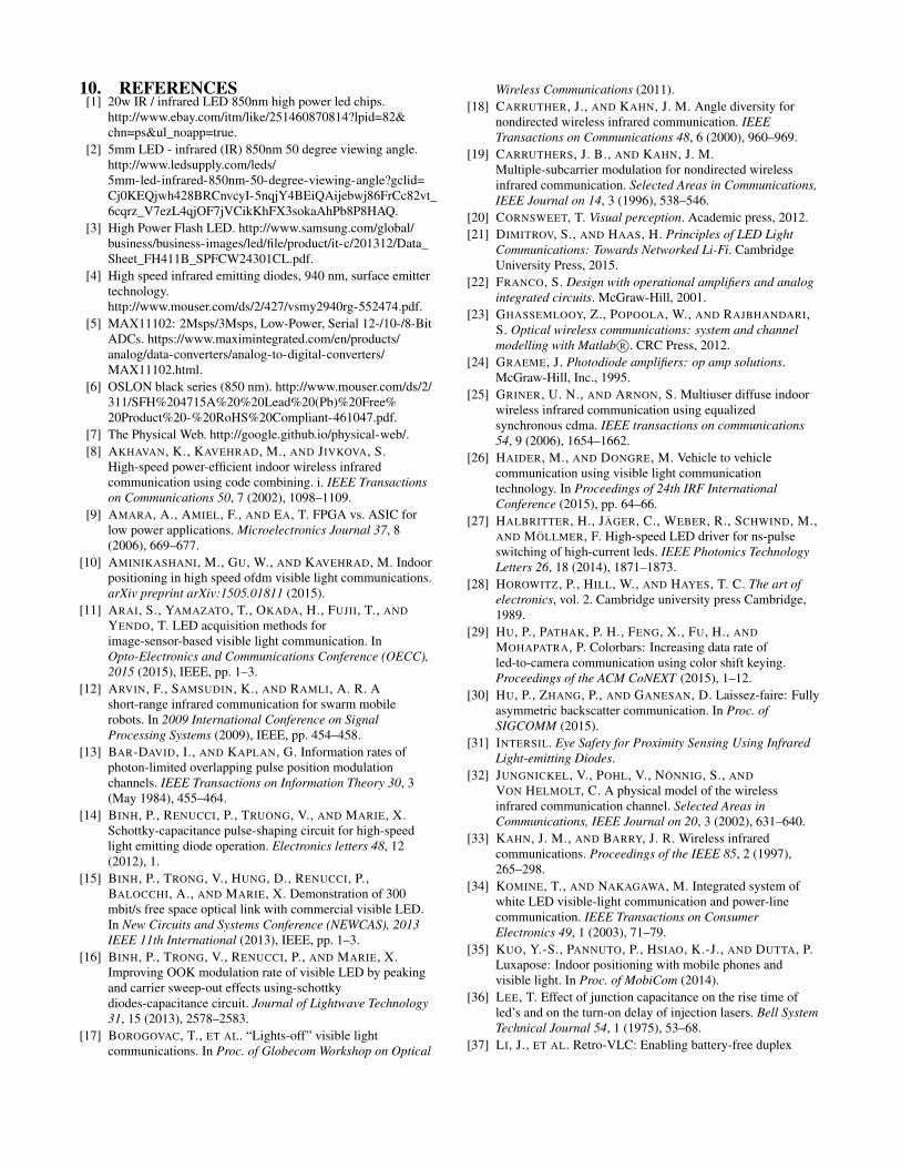
10. REFERENCES[1] 20w IR / infrared LED 850nm high power led chips.
http://www.ebay.com/itm/like/251460870814?lpid=82&chn=ps&ul_noapp=true.
[2] 5mm LED - infrared (IR) 850nm 50 degree viewing angle.http://www.ledsupply.com/leds/5mm-led-infrared-850nm-50-degree-viewing-angle?gclid=Cj0KEQjwh428BRCnvcyI-5nqjY4BEiQAijebwj86FrCc82vt_6cqrz_V7ezL4qjOF7jVCikKhFX3sokaAhPb8P8HAQ.
[3] High Power Flash LED. http://www.samsung.com/global/business/business-images/led/file/product/it-c/201312/Data_Sheet_FH411B_SPFCW24301CL.pdf.
[4] High speed infrared emitting diodes, 940 nm, surface emittertechnology.http://www.mouser.com/ds/2/427/vsmy2940rg-552474.pdf.
[5] MAX11102: 2Msps/3Msps, Low-Power, Serial 12-/10-/8-BitADCs. https://www.maximintegrated.com/en/products/analog/data-converters/analog-to-digital-converters/MAX11102.html.
[6] OSLON black series (850 nm). http://www.mouser.com/ds/2/311/SFH%204715A%20%20Lead%20(Pb)%20Free%20Product%20-%20RoHS%20Compliant-461047.pdf.
[7] The Physical Web. http://google.github.io/physical-web/.[8] AKHAVAN, K., KAVEHRAD, M., AND JIVKOVA, S.
High-speed power-efficient indoor wireless infraredcommunication using code combining. i. IEEE Transactionson Communications 50, 7 (2002), 1098–1109.
[9] AMARA, A., AMIEL, F., AND EA, T. FPGA vs. ASIC forlow power applications. Microelectronics Journal 37, 8(2006), 669–677.
[10] AMINIKASHANI, M., GU, W., AND KAVEHRAD, M. Indoorpositioning in high speed ofdm visible light communications.arXiv preprint arXiv:1505.01811 (2015).
[11] ARAI, S., YAMAZATO, T., OKADA, H., FUJII, T., ANDYENDO, T. LED acquisition methods forimage-sensor-based visible light communication. InOpto-Electronics and Communications Conference (OECC),2015 (2015), IEEE, pp. 1–3.
[12] ARVIN, F., SAMSUDIN, K., AND RAMLI, A. R. Ashort-range infrared communication for swarm mobilerobots. In 2009 International Conference on SignalProcessing Systems (2009), IEEE, pp. 454–458.
[13] BAR-DAVID, I., AND KAPLAN, G. Information rates ofphoton-limited overlapping pulse position modulationchannels. IEEE Transactions on Information Theory 30, 3(May 1984), 455–464.
[14] BINH, P., RENUCCI, P., TRUONG, V., AND MARIE, X.Schottky-capacitance pulse-shaping circuit for high-speedlight emitting diode operation. Electronics letters 48, 12(2012), 1.
[15] BINH, P., TRONG, V., HUNG, D., RENUCCI, P.,BALOCCHI, A., AND MARIE, X. Demonstration of 300mbit/s free space optical link with commercial visible LED.In New Circuits and Systems Conference (NEWCAS), 2013IEEE 11th International (2013), IEEE, pp. 1–3.
[16] BINH, P., TRONG, V., RENUCCI, P., AND MARIE, X.Improving OOK modulation rate of visible LED by peakingand carrier sweep-out effects using-schottkydiodes-capacitance circuit. Journal of Lightwave Technology31, 15 (2013), 2578–2583.
[17] BOROGOVAC, T., ET AL. “Lights-off” visible lightcommunications. In Proc. of Globecom Workshop on Optical
Wireless Communications (2011).[18] CARRUTHER, J., AND KAHN, J. M. Angle diversity for
nondirected wireless infrared communication. IEEETransactions on Communications 48, 6 (2000), 960–969.
[19] CARRUTHERS, J. B., AND KAHN, J. M.Multiple-subcarrier modulation for nondirected wirelessinfrared communication. Selected Areas in Communications,IEEE Journal on 14, 3 (1996), 538–546.
[20] CORNSWEET, T. Visual perception. Academic press, 2012.[21] DIMITROV, S., AND HAAS, H. Principles of LED Light
Communications: Towards Networked Li-Fi. CambridgeUniversity Press, 2015.
[22] FRANCO, S. Design with operational amplifiers and analogintegrated circuits. McGraw-Hill, 2001.
[23] GHASSEMLOOY, Z., POPOOLA, W., AND RAJBHANDARI,S. Optical wireless communications: system and channelmodelling with Matlab R©. CRC Press, 2012.
[24] GRAEME, J. Photodiode amplifiers: op amp solutions.McGraw-Hill, Inc., 1995.
[25] GRINER, U. N., AND ARNON, S. Multiuser diffuse indoorwireless infrared communication using equalizedsynchronous cdma. IEEE transactions on communications54, 9 (2006), 1654–1662.
[26] HAIDER, M., AND DONGRE, M. Vehicle to vehiclecommunication using visible light communicationtechnology. In Proceedings of 24th IRF InternationalConference (2015), pp. 64–66.
[27] HALBRITTER, H., JÄGER, C., WEBER, R., SCHWIND, M.,AND MÖLLMER, F. High-speed LED driver for ns-pulseswitching of high-current leds. IEEE Photonics TechnologyLetters 26, 18 (2014), 1871–1873.
[28] HOROWITZ, P., HILL, W., AND HAYES, T. C. The art ofelectronics, vol. 2. Cambridge university press Cambridge,1989.
[29] HU, P., PATHAK, P. H., FENG, X., FU, H., ANDMOHAPATRA, P. Colorbars: Increasing data rate ofled-to-camera communication using color shift keying.Proceedings of the ACM CoNEXT (2015), 1–12.
[30] HU, P., ZHANG, P., AND GANESAN, D. Laissez-faire: Fullyasymmetric backscatter communication. In Proc. ofSIGCOMM (2015).
[31] INTERSIL. Eye Safety for Proximity Sensing Using InfraredLight-emitting Diodes.
[32] JUNGNICKEL, V., POHL, V., NÖNNIG, S., ANDVON HELMOLT, C. A physical model of the wirelessinfrared communication channel. Selected Areas inCommunications, IEEE Journal on 20, 3 (2002), 631–640.
[33] KAHN, J. M., AND BARRY, J. R. Wireless infraredcommunications. Proceedings of the IEEE 85, 2 (1997),265–298.
[34] KOMINE, T., AND NAKAGAWA, M. Integrated system ofwhite LED visible-light communication and power-linecommunication. IEEE Transactions on ConsumerElectronics 49, 1 (2003), 71–79.
[35] KUO, Y.-S., PANNUTO, P., HSIAO, K.-J., AND DUTTA, P.Luxapose: Indoor positioning with mobile phones andvisible light. In Proc. of MobiCom (2014).
[36] LEE, T. Effect of junction capacitance on the rise time ofled’s and on the turn-on delay of injection lasers. Bell SystemTechnical Journal 54, 1 (1975), 53–68.
[37] LI, J., ET AL. Retro-VLC: Enabling battery-free duplex

visible light communication for mobile and IoT applications.In Proc. of HotMobile (2015).
[38] LI, L., HU, P., PENG, C., SHEN, G., AND ZHAO, F.Epsilon: A visible light based positioning system. In Proc. ofNSDI (2014).
[39] LI, T., AN, C., TIAN, Z., CAMPBELL, A. T., AND ZHOU,X. Human sensing using visible light communication. InProc. of MobiCom (2015).
[40] LI, T., LIU, Q., AND ZHOU, X. Practical Human Sensing inthe Light. In Proc. of MobiSys (2016).
[41] NOSHAD, M., AND BRANDT-PEARCE, M. ExpurgatedPPM using symmetric balanced incomplete block designs.Communications Letters, IEEE 16, 7 (2012), 968–971.
[42] PALMER, S. E. Vision science: Photons to phenomenology,vol. 1. MIT press Cambridge, MA, 1999.
[43] SCHMID, S., ET AL. LED-to-LED visible lightcommunication networks. In Proc. of MobiHoc (2013).
[44] SHIU, D.-S., AND KAHN, J. M. Differential pulse-positionmodulation for power-efficient optical communication.Communications, IEEE Transactions on 47, 8 (1999),1201–1210.
[45] SUGIYAMA, H., AND NOSU, K. MPPM: a method forimproving the band-utilization efficiency in optical PPM.Lightwave Technology, Journal of 7, 3 (1989), 465–472.
[46] SZELISKI, R. Computer vision: algorithms andapplications. Springer Science & Business Media, 2010.
[47] TANG, A. P., KAHN, J. M., AND HO, K.-P. Wirelessinfrared communication links using multi-beam transmittersand imaging receivers. In Communications, 1996. ICC’96,Conference Record, Converging Technologies forTomorrow’s Applications. 1996 IEEE InternationalConference on (1996), vol. 1, IEEE, pp. 180–186.
[48] TIAN, Z., WRIGHT, K., AND ZHOU, X. The DarkLightrises: Visible light communication in the dark. In DartmouthCollege Computer Science Technical Report series (July2016). TR2016-814.
[49] TIAN, Z., WRIGHT, K., AND ZHOU, X. Lighting Up theInternet of Things with DarkVLC. In Proc. of HotMobile(2016).
[50] TYLER, C. W., AND HAMER, R. D. Analysis of visualmodulation sensitivity. iv. validity of the ferry–porter law.JOSA A 7, 4 (1990), 743–758.
[51] WANG, Q., GIUSTINIANO, D., AND GNAWALI, O.Low-cost, flexible and open platform for visible lightcommunication networks. In Proc. of HotWireless (2015).
[52] WANG, Q., GIUSTINIANO, D., AND PUCCINELLI, D.OpenVLC: Software-defined visible light embeddednetworks. In Proceedings of the 1st ACM MobiComworkshop on Visible light communication systems (2014),ACM, pp. 15–20.
[53] WANT, R., HOPPER, A., FALCAO, V., AND GIBBONS, J.The active badge location system. ACM Transactions onInformation Systems (TOIS) 10, 1 (1992), 91–102.
[54] WANT, R., SCHILIT, B., AND JENSON, S. Enabling theInternet of Things. Computer 48, 1 (Jan 2015), 28–35.
[55] XIE, B., TAN, G., AND HE, T. Spinlight: A high accuracyand robust light positioning system for indoor applications.In Proceedings of the 13th ACM Conference on EmbeddedNetworked Sensor Systems (2015), ACM, pp. 211–223.
[56] XU, Q., ZHENG, R., AND HRANILOVIC, S. Idyll: indoorlocalization using inertial and light sensors on smartphones.In Proceedings of the 2015 ACM International JointConference on Pervasive and Ubiquitous Computing (2015),ACM, pp. 307–318.
[57] YAMAZATO, T., KINOSHITA, M., ARAI, S., SOUKE, E.,YENDO, T., FUJII, T., KAMAKURA, K., AND OKADA, H.Vehicle motion and pixel illumination modeling for imagesensor based visible light communication. IEEE Journal onSelected Areas in Communications 33, 9 (2015), 1793–1805.
[58] YANG, Z., ET AL. Wearables can afford: Light-weightindoor positioning with visible light. In Proc. of MobiSys(2015).
[59] YOO, J.-H., JANG, J.-S., KWON, J., KIM, H.-C., SONG,D.-W., AND JUNG, S.-Y. Demonstration of vehicular visiblelight communication based on led headlamp. InternationalJournal of Automotive Technology 17, 2 (2016), 347–352.
[60] ZHANG, C., TABOR, J., ZHANG, J., AND ZHANG, X.Extending mobile interaction through near-field visible lightsensing. In Proc. of MobiCom (2015).
APPENDIXWe prove that the volume VE of the event space is (L−N ·θ)N−1.Based on symmetry, the event space consists of multiple parts ofequal volume V ′ and in each part, the points have different permu-tation. There are (N−1)! permutations for (N−1) points so thereare (N−1)! parts. Then we have VE = (N−1)! ·V ′. To calculateV ′, we assume x1 < x2 < . . . < xN−1 without generality. Thenwe can write one part as (eliminating the absolute value):
xi−1 + θ < xi < L− (N − i) · θ, ∀i ∈ [1, N − 1], (4)
where x0 = 0. Thus, the volume V ′ of the part can be calculatedas:
V ′ =
∫ L−(N−1)θ
θ
∫ L−(N−2)θ
x1+a
. . .
∫ L−θ
xN−2+θ
1 dxN−1 . . . dx2 dx1.
Define yi = xi − i · θ, ∀i ∈ [1, N − 1]. We can write V ′ as:
V ′ =
∫ L−Nθ
0
∫ L−Nθ
y1
. . .
∫ L−Nθ
yN−2
1 dyN−1 . . . dy2 dy1
=
∫ L−Nθ
0
. . .
∫ L−Nθ
yN−3
((L−Nθ)− yN−2) dyN−2 . . . dy1
Since∫ L−NθyN−3
((L−Nθ)−yN−2) dyN−2 = 12(yN−3−(L−Nθ))2,
we can derive
V ′ =(L−Nθ)N−1
(N − 1)!.
Thus VE = (N − 1)! · V ′ = (L−N · θ)N−1.