Embed Size (px)
Citation preview
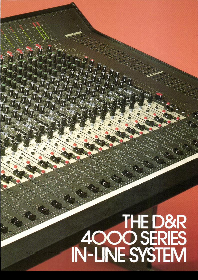

The D & R 4000 ser ies is d is t inguishable f rom the other desks, employ ing in- l ine mix ingin var ious ways. F i rs t ly a word about how we've achieved such technica l excel lencefo r such a compe t i t i ve p r i ce .We have emp loyed a p lug and f l a t cab le w i r i ng sys tem wh ich means tha t t he i nd i v i -dua l channe ls a re i n te rchangeab le w i th eacho the r t hus mak ing the desk fu l l y modu-la r . Ano the r t echn ica l i nnova t i on wh ich he lps ho ld the p r i ce o f t he 4000 se r ies downis a comp le te l y new way o f rou t i ng wh ich e l im ina tes the need fo r t he comp l i ca tedsw i t ch ing and w i r i ng c i r cu i t s f ound on conven t iona ldesks l ead ing to a sav ing o f 150sw i t ches on a 32 channe l m ixe r .
A s imp le pa tch -bay wh ich fac i l i t a tes ve ry easy pa tch ing i s a l so the resu l t o f ou r cos tconscious design ef for ts . The console i tse l f is o f a superb design, the modules are moun-ted i nd i v idua l l y i n a lum in ium "U" p ro f i l es w i th c lea r une rasab le l e t t e r i ng p ro tec ted bya po l yca rbona te f i lm . These p ro f i l es a re se t i n to the s tu rdy me ta l hous ing wh ich hasat t ract ive wooden s ides.
A comple te ly new approach to l im i t ing o fabove aud io range f requenc ies , th roughpass ive f i l te r ing ( ins tead o f the s tandardac t ive f i l te r ing) g ives th is conso le as a l lour o ther des igns an inc red ib le t ranspa-rancy th rough i t s absence o f t rans ien t d is -to r t ion . By c r i t i ca l l y damping every in te -gra ted c i rcu i t a t 40 KHz square waves wehave ach ieved comple te e l im ina t ion o fovershoot and/or r ing ing and s lewing .A t t h e m i c i n o u t s a l l t h e a m o l i f i c a t i o n i sper fo rmed by d isc re te low no ise t rans is -to rs and th roughout the s igna l pa th by
B i -Fet op-amp (ser ies TL 070) , wh i le the mix inga m p u t i l i s e t h e r e k n o w n e d i n d u s t r i a l s t a n d a r dlow no ise aud io op-amp NE 5534AN.We have chosen fo r a min imum aud iopath toach ieve to ta l t ransparancy . Due to an exce l -l e n t c i r c u i t d e s i g n t h e r e i s a m i n i m u m o fc ross ta lk , con t ro l in te rac t ion and th is combi -ned w i th the superb pr in ted c i rcu i t board lay -ou t con t r ibu tes to a very s tab le and low no iseproduc t .
A rundown of the ser ies 4000 possibi l i t ies
1 1 segment posit ive/negat ive reading peak-bargraph meter per in /ou tpu t channe l
48V phantom power ing , sw i tchab le perc h a n n e l
c l i ck f ree phase reverse swi tch fo r mic / l inea n d r e m i x s i g n a l s e n t e r i n g t h e c o n s o l e
ex t remely low no ise e lec t ron ica l l y R.F .screened, ba lanced mic amps
s imul taneous sync / remix inputs fo r + 4 dBua s w e l l a s - 1 0 d B V
1 0 0 H z h i g h - p a s s f i l t e r
4 band sweep eq. of novel design withoutin te rac t in g cont ro l func t ions
6 aux sends pre/post switchable and selec-tab le f rom channe l and mon i to r s igna ls pa ths
comple te ly new f ree f loa t ing in /ou tpu tsf rom subgroup amps mak ing subgroup ing toa n y m u l t i t r a c k c h a n n e l p o s s i b l e w i t h a m i n i -mum of sw i tches
s imu l taneous rou t ing to master , d i rec t ou t -p u t a n d g r o u p s u m m i n g a m p s p o s s i b l e
sync and e f fec t inpu ts per channe l , chan-g ing a 24 conso le in to a 48 l ine input remixconsote
m o n i t o r m u t e a n d p . f . l .c h a n n e l m u t e a n d p . f . l .100 mm channe l fader ,60 mm moni to r fader2 inser ts per channe ls imu l taneous mul t i t rack feed ou tpu ts fo r
+ 4 d B u a n d - 1 0 d B V a v a i l a b l emaster sect ion with 25 segment led bars
and ohase correlat ion meterlow d is to r t ion 1 KHz l ine up osc i l la to rta lkback w i th bu i l t in e lec t re t and rou t ingcommunica t ion sys tem swi tchab le v ia the
a. f . l . /p . f . l . sys tem6 master aux sends w i th ind iv ldua l se lec-
tab le a . f . l . sw i tchescomprehensive control room monitor sec-
t ion with al ternat ive monitor loudspeaker swit-c h i n g , m o n o s w i t c h a n d m u t e s w i t c h i n g
two stereo master recorders can be playedb a c k ( + 4 d B u / - 1 0 d B V i n p u t s a v a i l a b l e )
modu lar 64 po in t pa tchbay modu lesa l l connect ions v ia XLR and jackp lugssub mstr in groups possible

The 11 segment ledbar ( the f i rs t led ind ica-tes only that the power supply is on) is apeakreading instrument indicat ing both po-si t ive and negat ive peaks which is absolu-tely necessary in modern recording.
Below the ledbar sect ion are the input cir-cui t controls and switches. The f i rst beingthe, per channel, switchable + 48V phantompower supply. Below this is the - 20 dB pad,necessary for extremely high input signalso n t h e m i c i n p u t .
The l ine swi tch changes the XLR input tol ine level sensit iv i ty and also changes theba lanced mic input connect ion in to an un-ba lanced l ine input . The input sens i t i v i t yr a n g e s f r o m - 1 0 d B u t o + 2 0 d B u .
The remix switch, which also act ivates al ine leve l inpu t has pr io r i t y over the l ineswi tch . The remix input i s combined w i ththe sync input on the back of the console.
The ga in cont ro l ac ts fo r the mic ampl i f ie ras a feedback control and in the l ine/remixmode as an input a t tenuator . The mic ga inranges from - 20 dB to - 64 dB whi lst pro-v id ing an enormous headroom wi th a min i -mum of 40 dB.
This phase.reversal switch is active on bothmic and l ine/remix inputs which proves han-dy in al l sorts of recording si tuat ions.
The high-pass f i l ter is a f ixed frequency f i l -ter with a - 3dB turn over frequency at 100Hz. The slope is 9 dB per octave.
The equal izer stands out by vir tue of i ts s im-ple yet ef fect ive design, with a minimum au-d iopath wh ich guarantees a good s igna l tonoise rat io. l t is of a parametr ic 4 band de-s ign wh ich spans the who le aud io spec-t rum. The h igh she lves a t 12 KHz and thelow at 60 Hz. The high midranges from '1
KHz to 11 KHz and the low midranges from100 Hz to 1 KHz. The l i f t and cut range ofa l l 4 equa l izer sec t ions is + 16 dB. Thepoint of turnover frequencies in this equa-l i zer w i l l p leasant ly surpr ise you. In theeventual i ty of st i l l further equal isat ion beingnecessary there fol lows an insert ion pointwhich makes insert ion of addit ional e.q.units possible. The whole e.q. sect ion is by-passab le w i th a s i len t sw i tch .
The 4000 series offers in total 6 individualaux sends which easi ly al lows for the mostextensive remix sessions. The aux sendsare per pair switchable pre/post the moni-tor/channel fader. Basical ly the 6 sends arewired pre/post the monitor fader which ma-kes i t possible to have foldback as wel l aseffect pre and post the mult i t rack machine.
This switch connects al l the 6 sendspre/post the channel fader this being neces-sary in the remix mode.
Subgrouping in the 4000 console is done ina new way and demands a new way of thin-king from the engineer. The basic idea is tohave subgroup ampl i f ie rs on ly where youneed them. This means that there is nogroup ampl i f ier preceeding every mult i t rackchannel as you might have been used to inconvent iona l in - l ine des igns .In the 4000 console there are only 8 sub-group ampl i f iers, only 8? Yes only 8, but the-se 8 subgroups are f ul ly f loat ing. You canswitch them to the inputs as wel l as to theoutputs anywhere in the console.lmag ine , rou t ing f rom channe l 1 to channe l28 w i thout pa tch ing , th is i s poss ib le in the4000 series in the fol lowing way.There are 8 switches for this novel rout ingsystem, 4 for going to the subgroups and4 for coming from the subgroups, cal led "tosub" and "from sub". l f you are not sub-group ing , the s igna l coming f rom the chan-nel fader goes direct ly to the mult i t rack ma-chine. But let 's say you want to stereo sub-group channe l 1 to 8 to mu l t i t rack channe l1 and 2. This means that you need 2 sub-groups because you want to do i t in stereo.The f i rst thing you have to do is to br ing thes igna ls to the subgroups by push ing theswitch marked "to sub 1/2"(you are usingnow subgroup 1 and 2). The pan-pot deter-mines the s igna l leve l sen t to subgroup 1and/or 2, depending on i ts posi t ion, lef t ,r igh t o r cen t ra l . The s igna ls coming f romchannel 1 to 8 are now brought to subgroup1 and 2 (physical ly located in the mastersect ion). But, now, you need them on mul-t i t rack channel 1 and 2. You only have toconnect the mult i t rack inputs to the outputsof the subgroup amps. This is done by swit-ch ing the " f rom sub 72" sw i tches .
As already de-scr ibed above, this con-trof (with a -4" dB attenuat ion when setcentral) pans the signal between the oddand even subgroups as wel l as lef t / r ightmaster buss. i f selected.
In the on-posit ion, the monitor sect ion in thechanne l i s sw i tched f rom the input to theoutpu t o f the mul t i t rack mach ine .
lf it is necessary to control the overall levelgoing to the multitrack, the submaster switchinserts the monitor fader in the signal path.
The switch "effect" makes it possible to usethe monitor sect ions as effect returns. Inthis manner you have control over as manyeffect returns as the console has channels.

The p.f . l . switch enables you to prefadel isten to the signal coming from the chan-nel or f rom the mult i t rack as wel l as fromthe effect input.Mut ing is done by cance l l ing the s igna l co-ming from the channel, sync or effect in-puts. The p.f . l . is not af fected by muting.
This smal l fader, 58 mm travel, is of thecarbontrack type.
The p.f . l . and mute switches in the channelshave the same functions as the monitor sec-t ions. The p.f . l . does not interrupt the sig-nal path. The mute funct ion has a led to in-dicate i ts funct ion.
The channel fader is of the carbontrack ty-pe with a 100 mm length. Standard is the J.P.fader. Options are A.L.P.S. and Penny andGiles.
On the back of the console you wi l l f ind thein/outputs of the channels. On the top the-re is the XLR type input connector for themic and Line amp. Next there is the combi-ned sync/remix input which accepts two le-ve ls , +4dBu ( the pro fess iona l s tandard)and the - 10 dBV which is the semi-profes-sional standard. Mult i t rack Feed is the out-pu t o f the channe l wh ich has to be p luggedinto the input of the mult i t rack machine. Onth is socket a lso there are +4dBu and- 10 dBV levels avai lable. The channel in-sert is the jack into which you can insertanci l lary equipment such as compressorsnoise gates and other frequently used effectdevices. The effect jack is there as an ex-t ra l ine input in the remix s i tua t ion .The monitor insert is there to make possibleextra equal iz ing or the insert ion of otheranc i l la ry equ ipment in the mon i to r ing sec-t ion o f the channe l .
First there are the extremely precise 25 seg-ment peak reading ledbars with both a po-
s i t i ve and negat ive read ing d isp lay . Be lowth is ledbars i s the phase cor re la t ion meterwhich is wired in paral lelwith t ie ledbar me-te rs . The osc i l la to r i s o f the phase sh i f t t y -pe which produces a low distort ion 1 KHzsinewave. The 4000 series offers the possi-b i l i t y o f comprehens ive communica t ionfrom the studio to the control room at al l t i -mes and in al l stages of a session. l t is alsopossible to speak f rom the control room tothe s tud io v ia a l l ou tgo ing l ines by meansof the aux ou tpu ts . The s la te swi tch makesi t poss ib le to pu t in fo rmat ion on tape. Byuse o f the ta lkback swi tch the C.R.M. i s a t -tenuated by 20 dB. There is a h igh qua l i t y ,bu i l t in , e lec t re t m ic rophone fo r ta lkbackpurposes . A h igh pass f i l te r fu r ther inc rea-ses the clar i ty.
The 6 aux masters w i th the i r a . f . l . sw i tchescont ro l the to ta l ou tgo ing leve l o f the auxsends.
C.R.M. s tands fo r Cont ro l Room Moni to rand regu la tes the leve l o f a l l the s igna lsgo ing to the cont ro l mon i to r . The s te reo 1and 2 switch make i t possible to select f rom2 stereo sources instead of the master mixdown. The mono switch makes comparisonbetween stereo and mono possible. Mutecance ls the mon i to r comple te ly . A l t . mon.s tands fo r a l te rna t ive mon i to r ing . l t i s pos-sible with this switch to br ing in another mo-nitor system i f one is connected. Noble fa-ders are standard but A.L.P.S. or Penny andGi les a re ava i lab le op t iona l l y .
The patchbay is modular and has provisionfor 64 break patch-points per module. Theconnect ions between the patch-points andthe socket at the rear of the console are ma-de v ia two pr in ted c i rcu i t boards wh ich ha-ve at the back molex pin connectors. In thisway you can br ing any in /ou tpu t jack to thepatchbay by means o f s imp le ex terna l w i -r ing and further i t is an economical methodwhich saves t ime.
-I:IT?gr{c B
t${
$F
- I r-_l r E l | T t f f r T n r u r u r o t l : r o
s p " . , . . e . l O R e r o d B L . ! . r : : 1 5 d B w r i n a s p . . d n L s . c P , p . . s p . . a , L n f r r s . . L T N E A R
-FREOUETCY
i ; . , . " ' ' -uo, ' i - [ T Ir . ; ' * ' - ;^";"*
- ;

Notes: Nominal operat ing level throughout the console is 0 dBu (o.775 v)-Nominal output level is + 4 dBu/- 10dBu.
e lec t ron ica l l y ba lanced R.F . suppressed.input impedance 2 kOhmgain + 64 dB to + 0 dB (44 dB var iab lega in w i th 20 dB "pad" )h e a d r o o m m i n . 4 0 d B M a x i n o u t + 2 0 d Bno ise - 126 dB (A we igh t ing)
input impedance 10 kOhmgain f rom - 10 dBu to in f in i t yheadroom 22 dBEqu iva len t inpu t no ise- 96.5 dB (20-20.000H2)frequency response referred to0 dB a t 1 kHz l -0 .5 dB a t 8 Hz-0 .5 d B a t 140 kHz l -3 dB a t 400 kHz
a 16 dB at 12 kHz+ 16 dB f rom 1 kHz to 11 kHz w i thQ fac tor 1 .5
+ 16 dB f rom 100 Hz to 1 kHz w i thQ factor '1.5
t 1 6 d B a t 6 0 H zhigh pass 100 Hzslope 9 dB per octave
Test condit ion; One channel, assigned to and fromgroupbuss output,microphone input loaded with a 150 ohmsource , mic p reamp se t fo r 30 dB ga in , g roup ou tpu t +4 dBufrequency response referred to0 dB at 1 kHz -0.5 dB at 20 Hz and 2OkHzNoise -84dBu be low + 4 dBu ou tDut
Record modeDirect Assign between two channels both at 30 dB gain +4 dBu out o f channe l 1 , 150 ohm source on channe l 2 inout .
Crosstalk on channel 2 (referred to + 4 dBu)
100 Hz better than -88 dB1 kHz better than -90 dB
10 kHz be t te r than -74 dB
sync /e f fec t inpu t impedance 10 kOhmsync sens . +4 dBu/ - 10 dBu. E f fec t sens 0 dBu.Output impedance 100 ohm on a l l ou tpu tsmax ou tpu t +22 dB in to 1 kOhm and above
f requency response -0 .5 dB a t 17 Hzf rom l ine inputs to s te reo mix buss ou tpu tsre f to 0 dB a t 1 kHz l -0 .5 dB a t 40kHz/ -3 dB a t 135 kHzdistort ion no more than 0.009% at 1 kHzheadroom +22 dB, ou tpu t amp + 18 dBNoise -84 dB below + 4 dBu (20-20.000 Hz) measured at
the stereo buss outouts with stereo master fader atmax. al l channel faders at ful l attenuation panpots atthe i r cen ter oos i t ions
-83 dB below + 4 dBu (20-20.000 Hz) with one channel fa-der a t un i ty ga in
Channel 1 is fed with +4 dB, fader at unity panned to left . Stereo master fader at maximum.Channel 2 is terminated with a 20 ohm source. Fader at unity, panned to r ight stereo master.Cross ta lk on r igh t master ou tpu t : 100 Hz be t te r than -77 dB l l k1z be t te r ihan -70 dB/10 kHz be t te r than -63 dB
i__tWIDTH20 modules 1060 mm30 modules 1530 mm40 modules 2000 mm
L o___.] >! L
R o _ _ l > J '
V
950mm