Embed Size (px)
Citation preview


2
The cover in composite material
INDUSTRIE POLIECO-MPB s.r.l. VIA E. MATTEI, 49
25046 - Cazzago San Martino (BRESCIA - ITALY) Tel.++39 030 7758911 Fax ++39 030 7750845
e-mail: [email protected] http: www.kio-polieco.com

3
POLIECO GROUP is the European leader in producing and marketing twin-wall corrugated pipes in high density polyethylene. The first in Italy, since 1992, to produce corrugated cable conduit in polyethylene for electric and telephone networks and, in 1995, corrugated pipes for sewerage not under pressure. POLIECO GROUP is today an international reality with various production units in Italy, France, Spain, Greece and Slovak Republic. During 2010, Industrie Polieco-MPB decided to develop a project for the manufacturing of manhole tops made of composite material. Manhole tops are currently almost exclusively made in spheroidal cast iron, lamellar cast iron or concrete. In recent years the European market has been invaded by products from Asian countries, even of doubtful quality. Having perceived the potential ofcomposites, small manufacturers of manhole tops made of composite material have also appeared on the market. At presentsome of these manufacturers have developed production methods at handmade level only and, in particular, without any guarantee of repeatability of the load bearing capacity, whereas others are proposing their products for niche applications only. POLIECO GROUP today introduces KIO, the composite material cover, in the same classes and similar dimensions to the cast iron ones as foreseen by EN124 reference standard. POLIECO is UNI EN ISO 9001:2008 certified. In December 2005 , POLIECO also obtained the Environmental Management System certificate of conformity according toUNI EN ISO 14001:2004 reference standard. This technical manual intended for public and private designers and users, provides information on: the product, raw materials used, applicable reference Standard, and testing methods and the advantages of composites covers compared to cast iron ones.
Cazzago San Martino, February 2012

4
CHAPTER 1. INTRODUCTION ______________________________________________ 5
CHAPTER 2. THE COMPOSITE MATERIAL __________________________________ 5
CHAPTER 2. THE COMPOSITE MATERIAL __________________________________ 6 2. 1 − THE GLASS FIBRE _______________________________________________________ 6
CHAPTER 3. THE PRODUCT _______________________________________________ 7
CHAPTER 3. THE PRODUCT _______________________________________________ 8 3. 1 − THE PRODUCT __________________________________________________________ 8 3. 2 − MANUFACTURING PROCESS _____________________________________________ 9 3. 3 − ADVANTAGES OF THE COMPOSITE MATERIAL COVER __________________ 10
3. 3. 1 − LIGHTNESS AND HANDINESS ________________________________________________ 10 3. 3. 2 − RESISTANCE TO CORROSION AND CHEMICAL SUBSTANCES _____________________ 11 3. 3. 3 − NOISE REDUCTION_________________________________________________________ 11 3. 3. 4 − ELECTRICAL AND THERMAL INSULATION _____________________________________ 11 3. 3. 5 − ENVIRONMENT PROTECTION ________________________________________________ 12 3. 3. 6 − THEFT PREVENTION________________________________________________________ 12 3. 3. 7 − CUSTOMISATION __________________________________________________________ 12
CHAPTER 4. THE REFERENCE STANDARD_________________________________ 13 4. 1 − MARKING ______________________________________________________________ 14
CHAPTER 5. THE LABORATORY TESTS ____________________________________ 14
CHAPTER 5. THE LABORATORY TESTS ____________________________________ 15 5. 1 − CONFORMITY TO EN 124:1994 ___________________________________________ 15
5. 1. 1 − PERMANENT SET___________________________________________________________ 15 5. 1. 2 − LOAD BEARING CAPACITY___________________________________________________ 16
5. 2 − CONFORMITY TO prEN 124 – Part 5:2011__________________________________ 16 5. 2. 1 − DEFLECTION UNDER LOAD __________________________________________________ 17 5. 2. 2 − CREEP RESISTANCE ________________________________________________________ 17 5. 2. 3 − RESISTANCE TO FATIGUE ___________________________________________________ 17 5. 2. 4 − IMPACT RESISTANCE _______________________________________________________ 17 5. 2. 5 − EFFECT OF HEATING _______________________________________________________ 17 5. 2. 6 − COMPOSITE MATERIAL REQUIREMENTS ______________________________________ 18
5. 3 − CERTIFICATION________________________________________________________ 18
CHAPTER 6. INSTALLATION AND BEDDING _______________________________ 20

5
CHAPTER 1. INTRODUCTION Research for lightness in a product, the cover, normally considered heavy: lightness where high mechanical resistance and durability in time are requested: the innovative KIO cover demolishes the obvious to simplify life: simplified handling, laying and maintenance, greater number of pieces which can be transported on a single load, reduced environmental impact, excellent mechanical properties and resistance to chemical agents. In recent years the use of composite material established itself in the aeronautical and automotive industry and diffused in many sectors due to the combination of lightness and handiness with resistance and duration greater than the traditional materials (concrete and ferrous materials). For the first time in Italy Industrie Polieco-MPB Srl has developed and manufactured KIO, the composite material cover.

6
CHAPTER 2. THE COMPOSITE MATERIAL Composite materials are complex materials in which two or more constituent materials (with significantly different physical or chemical properties) are combined to produce structural or functional properties not present in any individual component: compared to traditional materials, the composite materials are sturdy and light at the same time, with excellent resistance to corrosion and chemical agents, with high electrical and thermal insulation properties. The composite material used for manufacturing the KIO cover consists of a long fibres reinforcement adequately encapsulated within a thermoset matrix resin. Thermoset matrix resins are polymers that, once produced, become infusible and insoluble, as a result of the formation during the production process of a three-dimensional networkof strong covalent bonds, which make the process irreversible. The formulation of the thermosetting resin used for manufacturing KIO was developed to maximise the mechanical properties of the finished product in terms of both mechanical and impact resistance and to have excellent processability conditions. The reinforcing fibre is the glass fibre: compared to traditional glass fibres, the grade selected for KIO is characterised by excellent mechanical and electrical properties, improved resistance to corrosion by acids, improved resistance to high and low temperatures and excellent behaviour to stress-corrosion cracking.
2. 1 − THE GLASS FIBRE
The glass fibres are one of the most known reinforcing materials, widely used for manufacturing composite materials. Common experience says monolithic glass is a brittle material due to the large number of defects of crystallisation acting as microfaults and areas of concentration of the stresses. Whereas, if it is spun to a diameter less than one micron, it loses its characteristic weakness to become a material with high mechanical resistance and resilience: these characteristics are also maintained at very high temperatures. To manufacture glass fibres with high resistance to traction, flexibility, dimensional stability and resistance to corrosion a glass raw material with particular chemical-physical features is required; the vitrifiable mixture is melted at high temperature, made homogenous and subsequently refined so that all air bubbles and impurities are fully eliminated; impurities if present would break the fibres and stop production. Indeed the manufacturing process of the continuous filament consists in extruding the molten glass through platinum dies having several 1-2 mm diameter holes. Viscous glass drops are formed, kept at a high temperature and mechanically stretched to form filaments wound around drums rotating at high velocity. The mechanical effect of stretching and winding is not sufficient to keep the filaments together in a long-lasting way, in a single thread or in a fibre ribbon. The glass is too smooth to agglomerate; furthermore, it is sensitive to friction, abrasion and static electricity, phenomena that can increase when proceeding with weaving or other transformations. For this reason, when the filaments come out of the die they are softened and coated with thin layers of organic compounds, called sizing.

7
The purpose of the protective coating on the glass surface is to:
- agglomerate the filaments when twisted to form a single thread and protec the single filaments against abrasion;
- cover them with a lubricating film; - ensure proper bonding to the resin matrix, thus allowing for transfer of shear loads
from the glass fibers to the thermoset plastic (without this bonding, the fibers can 'slip' in the matrix and localised failure would ensue)
Some properties typical of the glass fibres we use for manufacturing the KIO cover are listed in the following Table 1.
Density of filaments about 2.6 g/cm3 Tensile strength 3000 ÷ 3700 MPa Elongation at break 4,2 ÷ 4,5% Young modulus 72 ÷ 74 GPa Moisture content < 0,2% Heat conductivity λ 1.0 W/m °K Coefficient of linear thermal expansion (between 20 and 100°C)
approx. 6 * 10-6 m/m/°K
Reaction to fire fire-proof Dielectric strength (glass in mass) 60 – 100 KV/mm
Table 1 – Properties of the glass fibre

8
CHAPTER 3. THE PRODUCT
3. 1 − THE PRODUCT
are The three essential elements for choosing the cover are: the class, the clear opening and the shape. The appropriate class depends upon the place of installation. The various places of installation have been divided into groups numbered 1 to 6 as described in the following table 2. Reported in the third column of the same table is a guide on the class to use for each group. The selection of the appropriate class is the responsibility of the designer.
Place of installation Group Class Load bearing capacity 15 kN. Areas which can only be used by pedestrians and pedal cyclists.
Group 1 Min. A 15
Load bearing capacity 125 kN. Footways, pedestrian areas and comparable – areas, car parks or car parking decks.
Group 2 Min. B125
Load bearing capacity 250 kN. For gully tops, installed in the area of kerbside channels of roads which, when measured from the kerb edge, extends a maximum of 0,5 m into the carriageway and a maximum of 0,2 m into the footway.
Group 3 Min. C250
Load bearing capacity 400 kN. Carriageways of roads (including pedestrian streets), hard shoulders and parking areas for all types of road vehicles.
Group 4 Min. D400
Load bearing capacity 600 kN. Areas imposing high wheel loads, e.g. docks, aircraft pavements.
Group 5 Min. E600
Load bearing capacity 900 kN. ): Areas imposing particularly high wheel loads, e.g. aircraft pavements.
Group 6 Min. F900
Table 2 – Place of installation
Figure 1 – Place of installation

9
The clear opening is the diameter of the largest circle that can be inscribed in the clear area of the frame, in other words the clear span of the cover. This value is normally unambiguous for all cover manufacturers and is equal to multiples of 100 mm. The external dimensions of both covers and frames are not subject to specifications. Therefore each manufacturer has different external dimensions for covers and frames , thus making the interchangeability of covers impossible. With regard to shape, on the Italian market square shapes starting with an external frame dimension of 300x300 mm and circular shapes of Φ800 mm (with a clear opening of 600 mm) are mostly present. The KIO cover is at present manufactured in the classes B125 and C250; the D400 class cover will soon be ready too. Frame external dimensions and clear openings are reported in the following Table 3.
Manhole top Frame external dimension (mm)
Clear opening (mm)
400 x 400 400 302 500 x 500 500 402 600 x 600 600 502 700 x 700 700 602
φ800 800 600
Table 3 – Frame and cover dimensions In addition to the KIO cover, we also produce the KIO grating. The reference standard prescribes precise parameters with regard to grating’s slots. Standard EN124 highlights that the slots must be designed so that the water way area shall not be less than 30% of the clear area and shall be given in the manufacturer’s catalogue. For Class C250 the slots must be from 16 to 32 mm wide and shorter than 170 mm.
3. 2 − MANUFACTURING PROCESS
The choice and the setting of the production process are just as important as the choice of raw materials: this is why for manufacturing KIO Industrie Polieco-MPB Srl decided to use a technology in which the production process is fully automated , and each step is controlled by a control system that allows for highly reproducible production, to guarantee quality and performances of the finished product. The KIO production process ensures excellent wettability of the fibres by the polymeric matrix, avoiding the formation of air bubbles and allows to get excellent interlaminar cohesion of the components. Indeed it is well known that the properties of composite materials strictly depend not only on the properties of their individual constituents, their shape, concentration and orientation, but also on their mutual interaction: the synergy
10
between the reinforcement and the polymer matrix is an essential requirement to obtain the desired physical-mechanical- properties.
3. 3 − ADVANTAGES OF THE COMPOSITE MATERIAL COVER
There are many advantages to the composite material cover compared to the cast iron or concrete ones already on the market: some of these advantages strictly related to the properties of the raw material used, others to the manufacturing process. Some of the advantages of the composite material covers are listed below.
3. 3. 1 − LIGHTNESS AND HANDINESS
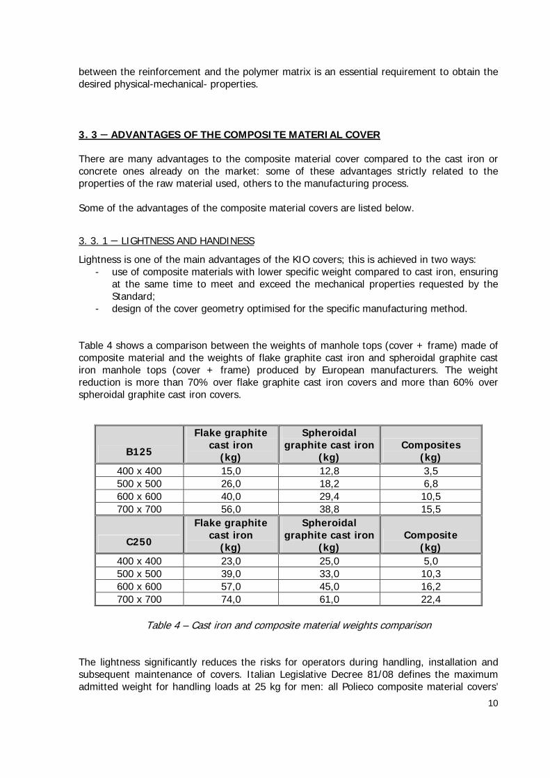
Lightness is one of the main advantages of the KIO covers; this is achieved in two ways: - use of composite materials with lower specific weight compared to cast iron, ensuring
at the same time to meet and exceed the mechanical properties requested by the Standard;
- design of the cover geometry optimised for the specific manufacturing method. Table 4 shows a comparison between the weights of manhole tops (cover + frame) made of composite material and the weights of flake graphite cast iron and spheroidal graphite cast iron manhole tops (cover + frame) produced by European manufacturers. The weight reduction is more than 70% over flake graphite cast iron covers and more than 60% over spheroidal graphite cast iron covers.
B125
Flake graphite cast iron
(kg)
Spheroidal graphite cast iron
(kg) Composites
(kg) 400 x 400 15,0 12,8 3,5 500 x 500 26,0 18,2 6,8 600 x 600 40,0 29,4 10,5 700 x 700 56,0 38,8 15,5
C250
Flake graphite cast iron
(kg)
Spheroidal graphite cast iron
(kg) Composite
(kg) 400 x 400 23,0 25,0 5,0 500 x 500 39,0 33,0 10,3 600 x 600 57,0 45,0 16,2 700 x 700 74,0 61,0 22,4
Table 4 – Cast iron and composite material weights comparison
The lightness significantly reduces the risks for operators during handling, installation and subsequent maintenance of covers. Italian Legislative Decree 81/08 defines the maximum admitted weight for handling loads at 25 kg for men: all Polieco composite material covers’

11
weigh is lower than said limit. For cast iron covers, two persons or mechanical tools are required for handling even the smaller dimensioned one.
3. 3. 2 − RESISTANCE TO CORROSION AND CHEMICAL SUBSTANCES
The composite material cover is not subject to corrosion phenomena or attacks by chemical substances: the surface of the cover is entirely made of a thermosetting resin, which is resistant to acid and alkaline substances, oils, greases and hydrocarbons. Only concetrated acid solutions (i.e. concentrated hydrochloric acid, sulphuric acid or nitric acid) or specific solvents (i.e. dimethylformamide) can adversely attack external surface of the cover. Together with the impossibility of creating sparks or condensation, this feature makes the composite material cover particularly suitable to be installed in refuelling stations or fuels storage plants. The use of said composite material covers instead of cast iron covers has become standard procedure in North European and American countries. Resistance to corrosion is also particularly important in drainage or sewage: the meteoric water conveyed through the gratings to the below piping system is certainly not polluted by passing through the grating's slots. The thermosetting resin used is also resistant to salty water: composite material covers are therefore particularly suitable in seaside areas. All this ensures that, unlike cast iron covers, the composite material cover has never to be painted.
3. 3. 3 − NOISE REDUCTION
The use of composite material frames and covers significantly reduces noise upon passing of vehicles or persons., The noise is typical of cast iron systems and it is due to the inadequate coupling between cover and frame or to laying errors.
3. 3. 4 − ELECTRICAL AND THERMAL INSULATION
The thermosetting resin external surface makes the cover a perfect insulating system, which prevents voltage dispersions and protects pedestrians and their animals against accidental electric shocks e.g. due to bare electric wires. Furthermore, the KIO cover is a low thermal conductor and protects against any hot steam leakages in district heating piping systems. The cover has minimum interference with the radio frequency, satellite or cell phone signals associated with modern transmission systems (e.g. meters, flow meters) installed inside underground manholes.
12
3. 3. 5 − ENVIRONMENT PROTECTION
As far as environment protection is concerned, the technology used by Polieco for manufacturing the composite material covers is highly innovative compared to the traditional manufacturing process of cast iron covers this technology ensures a remarkable reduction of CO2emission in the atmosphere compared to cast iron. This becomes clear when comparing the energy required to reach the temperature to mould cast iron (higher than 1200°C) and the energy required to reach the temperature to mould composite materials (around 60°C). The lower amount of CO2 released in the atmosphere is also strictly related to the lower weight of each single cover enabling to load on a truck a number of covers three times higher than cast iron covers with subsequent reduction of pollution due to the lower number of transports. To conclude note that the composite material can also be recycled for successive use, which allows a further reduction of the environmental impact of the product.
3. 3. 6 − THEFT PREVENTION
More or less every day we read that covers have been stolen to be sold and melt: the value of scrap iron is rising increasingly and the number of thefts to the detriment of local authorities and service companies are rising as well. Beside an economic damage caused by the need to replace the stolen products, there are also risks of serious accidents and injuries caused by unmarked dangerous openings on the road. As mentioned above, the composite material cover is recyclable but only through highly specialised processes and the obtained product can only be re-used for manufacturing particular pieces. The theft of composite material covers is not very attractive as there is no illegal secondary market.
3. 3. 7 − CUSTOMISATION
In addition to inserting the city, the service or the buyer's logo like for the cast iron covers currently on the market, there is also the possibility of producing covers and/or frames in different colours so as to identify a specific service or offer an aesthetical value to the laying of covers.

13
CHAPTER 4. THE REFERENCE STANDARD The KIO cover is manufactured in compliance with EN 124:1994 – “Gully tops and manhole tops for vehicular and pedestrian areas. Design requirements, type testing, marking, quality control”. EN 124:1994 is the standard presently in force; it specifies the dimensions, classes, materials, design and testing requirements, marking and quality control of gully tops and manhole tops with a clear opening up to and including 1000 m, for installation within areas subjected to vehicular and/or pedestrian traffic. The current Standard foresees the following materials: spheroidal graphite cast iron, flake graphite cast iron, cast steel, rolled steel or steel reinforced concrete. Other materials can be used provided that all the Standard requirements are met as well as any other relevant requirements established by an independent body, guaranteeing a third party control of the prescribed technical features. The above mentioned Standard is currently under revision by the Working Group CEN/TC165/WG4 “Covers, gratings, drainage channels and other ancillary components for use outside buildings”. The revised European Standard will be prepared under Mandate M/1181 given to CEN by the European Commission and the European Free Trade Association and it will establish the condition for CE marking of the products. The document will consists of the following parts:
Part 1: Classification, general design, performance and testing requirements, test methods and evaluation of conformity
Part 2: Gully tops and manhole tops made of cast iron Part 3: Gully tops and manhole tops made of steel, aluminium alloy Part 4: Gully tops and manhole tops made of steel reinforced concrete Part 5: Gully tops and manhole tops made of composite materials Part 6: Gully tops and manhole tops made of Polypropylene (PP), Polyethylene (PE)
or Polyvinyl-chloride (PVC-U) The revised standard will specifically foresee the use of different materials, among which composite materials defined in Part 5. Part 1 (Classification, general design, performance and testing requirements, test methods and evaluation of conformity) widely reprises the current standard in force. Additional requirements are:
- skid resistance: to prevent covers from potential skid, the surface skid resistance shall be assessed;
- child safety: where required by specific provisions in the place of intended use child safety features and/or devices shall be incorporated in the design of manhole tops and/or gully tops: this can be achieved by means of the mass of the individual covers or gratings or with locking accessory or securing feature
In addition to the requirements of Part 1, depending on the used materials the gully tops and manhole tops shall meet the requirements specified in Parts 2 – 6. 1 “Wastewater engineering products”

14
Additional tests have been introduced for some materials compared to that foreseen by EN 124:1994: for composite materials these tests are described in the subsequent paragraph 5.2.
4. 1 − MARKING
According to the Standard EN124:1994, the following information shall be clearly and lastingly reported on each cover, grating and frame:
- standard of reference (EN124) - the appropriate class - the name and/or identification mark of the manufacturer - the place of manufacture which may be in code - the mark of a certification body
According to the revised standard, covers, gratings and frames shall also bear the week or month and year of manufacture.

15
CHAPTER 5. THE LABORATORY TESTS
5. 1 − CONFORMITY TO EN 124:1994
The finite product shall be tested according to EN 124:1994. In particular, permanent set and load bearing capacity shall be measured to establish the appropriate class of the product. Design requirements shall also be verified to assess its fitness for purpose.
5. 1. 1 − PERMANENT SET
The test consists in measuring the permanent set (residual deflection) after the application of 2/3 of the test load for the relative class. Manhole tops shall be tested as complete units in their condition of service; the test sample shall be placed in the testing machine (preferably an hydraulic test press), with an appropriate test block (whose shape and dimensions are specified in the standard) placed on the test sample with its vertical axis perpendicular to the surface and coincidental with the geometric center of the cover. The initial reading at the geometric centre of the cover shall be taken. The load shall be applied at a rate of 1 to 5 kN/s up to 2/3 of the test load; the load on the test specimen shall then be released. This procedure shall be carried out 5 times. The final reading at the geometric centre of the specimen shall be taken at the end of the 5th cycle. The permanent set shall then be determined as the difference of the measured readings before the first and after the fifth cycle. The permanent set shall not exceed the values given in Table 5.
Class Permissible permanent set, mm
A 15 and B 125 CO100
1
C 250 to to F 900
CO3001
(2)
When secured by means of a locking device or a specific design
feature
CO5001
(3)
When secured by means of a sufficient mass per
unit area
(1) CO/50 when CODP < 450 mm (2) 1 mm max when CO < 300 mm (3) 1 mm max when CO < 500 mm CO = clear opening, mm; the diameter of the largest circle that can be inscribed in the clear area of the frame
Table 5 – Permissible permanent set
Permissible permanent set for the KIO cover are reported in the following Table 6.

16
Permissible pernmanent set Description
Clear opening (CO) mm
Class B 125 Class C250 KIO 400 x 400 302 6.04 mm 1.01 mm KIO 500 x 500 402 8.04 mm 1.34 mm KIO 600 x 600 502 5.02 mm 1.67 mm KIO 700 x 700 602 6.02 mm 2.01 mm
KIO φ800 600 6.00 mm 2.00 mm
Table 6 – Permissible permanent set for KIO cover
5. 1. 2 − LOAD BEARING CAPACITY
Immediately after the test described above, the test load FT (as reported in Table 7 for the different classes) shall be applied to the test sample at the same rate of 1 to 5 kN/s. The load shall be maintained for 30” and then released. The test samples shall not show visible cracks during the test and at the end of it.
Class Test load FT, kN A 15 15 B 125 125 C 250 250 D 400 400 E 600 600 F 900 900
Table 7 – Test loads
5. 2 − CONFORMITY TO prEN 124 – Part 5:2011
At present the Standard prEN124 – Part 5 (Gully tops and manhole tops made of composite materials) specifies additional requirements and test methods for manhole tops manufactured from composite materials compared to those reported in EN124:1994, as further guarantee of the suitability of the products for the intended use and of their durability in time. Cast iron covers are not subjected to these additional requirements. KIO fully meets all the additional requirements specified by prEN124 – part 5. The relevant test methods are briefly described below, as at present reported in the above mentioned standard. Useless to say that said tests (and requirements) may undergo changes during drafting of the reviewed standard.

17
5. 2. 1 − DEFLECTION UNDER LOAD
The test consists in measuring the deflection at the geometric centre of the manhole top (as would be supplied to the end user and that has not been subjected to any other test procedure) when loaded with a test load equal to 1/3 FT (refer to Table 7) At present no requirements are provided. The maximum deflection under load shall be recorded and declared as mm per mm of clear opening (CO).
5. 2. 2 − CREEP RESISTANCE
A load equal to that used for measuring the permanent set, which is equal to 2/3 of the test load for the relative class,, shall be applied to a manhole top that has not previously been subjected to any prior form of load test.. The load shall be applied for 60 minutes and then released; after a 5 minute recovery time, the product shall meet the requirements for permanent set repoeted in Table 5.
5. 2. 3 − RESISTANCE TO FATIGUE
A manhole top that has not been subjected to any other test procedure shall be subjected to a certain number of cycles (e.g. 10.000 cycles for class B125 and 50.000 cycles for class C250) of cyclic loads up to 1/3 of the test load for the relative class. Once the number of cycles is completed, the product shall meet the requirements for permanent set and load bearing capacity described in clauses 5.1.1 and 5.1.2..
5. 2. 4 − IMPACT RESISTANCE
A manhole top as would be supplied to the end user and that has not previously been subjected to a test load shall be conditioned at 60°C for 30 days, allowed to cool to room temperature for at least 2 hours and then conditioned at -20°C for at least 4 hours. Within 30 s, an appropriate mass (i.e. equal to 3.75 kg for class B125 and 4.5 kg for class C250) with a 50 mm diameter hemispherical end shall be dropped from a height of 2000 mm onto the geometrical centre of the test sample.. The impact test shall be repeated at a further 7 equally spaced points, 4 of which around the periphery. The piece shall be re-conditioned at -20°C for 10–15 minutes between impacts. At the end of the test there shall be neither visible cracking nor delamination.
5. 2. 5 − EFFECT OF HEATING
A sample previously subjected to the impact resistance test shall be conditioned in an oven for 60 minutes at 150°C: at the end of the test the sample shall not show visible defects, blistering, cracks or delaminations. Also the gratings (with their frames) shall be subjected to the same testing regime of covers.

18
5. 2. 6 − COMPOSITE MATERIAL REQUIREMENTS
At present prEN 124 Part 5 also specifies tests to assess some properties of the composite materials used for manufacturing the manhole tops, which are:
water absorption; hardness; resistance to vehicle fuels; resistance to abrasion; surface resistivity (only in the event that safety considerations require that the mahole
top is capable of dispersing a static electrical charge); weathering resistance (only in the event of specific extreme climate conditions).
Industrie Polieco-MPB Srl laboratory is already equipped for performing all the testing at present specified by pr-EN124 – Part 1 – General requirements and pr-EN124 – Part 5 – Composite materials.
5. 3 − CERTIFICATION
Industrie Polieco-MPB Srl obtained the cerificate of conformity according to the European Reference Standard EN 124:1994 for KIO manhole tops for all classes and all dimensions. The certificate was issued in March 2012 by the accredited certification body ICMQ (Istituto di certificazione e marchio qualità per prodotti e servizi per le costruzioni), once performed all the tests specified by EN124:1994 and also those specified by prEN 124 – part 5. Copy of the certificate is reported in the following page.

19

20
CHAPTER 6. INSTALLATION AND BEDDING Correct installation is an essential requirement in guaranteeing durability and efficiency of all building products, including manhole tops. In failed installations of manhole tops, regardless of their manufacturing materials, rocking of the frame and the cover can occur under traffic, causing damaging effect, like noise pollution and potential hazard to pedestrians and vehicles. A guide to the installation of manhole tops and gully tops has been prepared by a dedicated Technical Commission of UNI in the technical report UNI/TR 11256 (September 2007): Guide to the installation of gully tops and manhole tops for vehicular and pedestrian areas. This specification conceived for cast iron covers is also applicable to composite material manhole tops: their reduced weight makes the operations described in the above mentioned report easier, quicker, less dangerous and less subject to human errors. The phases and methods for the installation of a new manhole top are:
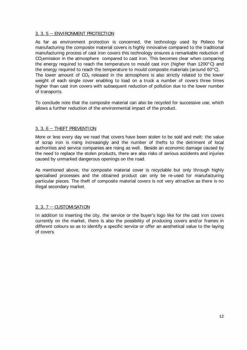
- compatibility between cover/frame and manhole A frame with the same clear opening of the manhole must be chosen so that the frame itself does not work in jerks. The following images report some examples highlighting the correct choice or not of the frame/cover (or grating) system compared to manholes, for square and round frames.
21
- preparation of the bedding layer The bedding layer must be prepared on the upper part of the manhole previously cleaned from debris, mud or dirt; the bedding layer must have an even thickness of 2 to 4 cm and must be smoothened to obtain a flat support base for the subsequent placing of the frame.
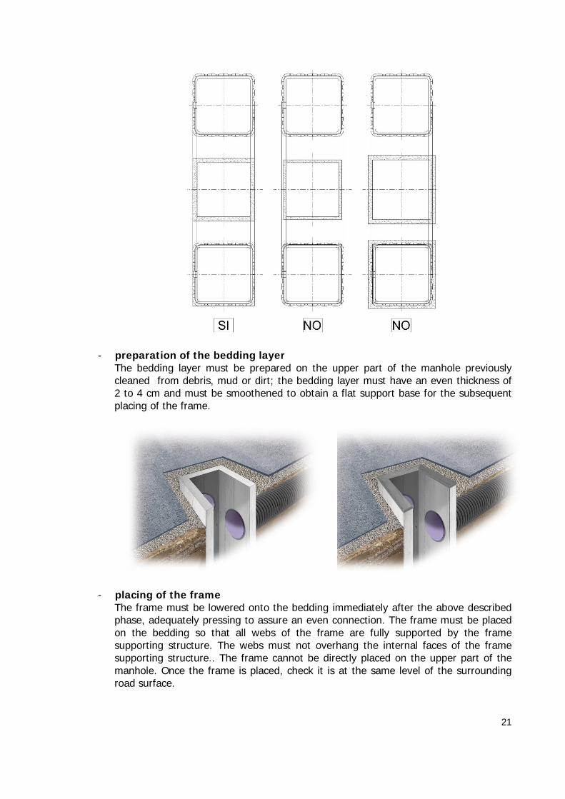
- placing of the frame The frame must be lowered onto the bedding immediately after the above described phase, adequately pressing to assure an even connection. The frame must be placed on the bedding so that all webs of the frame are fully supported by the frame supporting structure. The webs must not overhang the internal faces of the frame supporting structure.. The frame cannot be directly placed on the upper part of the manhole. Once the frame is placed, check it is at the same level of the surrounding road surface.

22
- placing of the cover The cover (or grating) can be placed inside the frame only once the bedding material has sufficiently set. Check that the inside of the frame is clean for an even and continuous support before placement. Secure the positioned cover/grating with manhole tops, if a locking device is provided.
- placement of cover surround materials Once the cover (or grating) has been placed and the bedding material has achieved sufficient tensile and compressive strength, complete the area around the cover; fill the surrounding area with bituminous material up to the upper rim of the frame. Avoid passing compaction devices over the recently installed manhole top to avoid damaging the bedding ,frame or cover (grating).