Embed Size (px)
Citation preview


1
THE PORT AUTHORITY OF NEW YORK AND NEW JERSEY OPERATIONS SERVICES DEPARTMENT
CENTRAL AUTOMOTIVE DIVISION 241 ERIE STREET, ROOM 307
JERSEY CITY, NEW JERSEY 07310-1397
DATE: December, 2015 CODE: 014-G7G815-4844
SPECIFICATIONS FOR:
AIRCRAFT REFUELING
10,000 GALLON TANKER VEHICLE SPECIFICATIONS 1. Intent
These specifications cover the furnishing of forty-five (45) latest production model 10,000 Gallon Aircraft Refueling Tanker Vehicles for Aircraft Refueling operations at Newark Liberty International Airport and JFK International Airport. These vehicles shall be provided at each Airport as follows: Twenty (25) 10,000 Gallon Aircraft Refueling Tanker Vehicles at Newark
Liberty International Airport Twenty (20) 10,000 Gallon Aircraft Refueling Tanker Vehicles at JFK
International Airport The vehicles shall be the manufacturer’s latest production model available and equipped with all manufacturer stock or standard equipment, and also equipped with the specific components and the optional equipment for each vehicle as listed within these specifications. The vehicles shall also have all other equipment, parts or components that are necessary and/or appropriate for the operational intent of the vehicles. The Contractor shall complete the Bidder’s Pricing Sheet located in Appendix C, listing the Price for each vehicle and listing the Grand Total Bid Price that will be used to evaluate the bid. Note: The bid shall be evaluated based on the Grand Total Price listed in the Bid Evaluation Pricing.

2
Although the vehicles are being purchased by the Port Authority of NY & NJ, they will be operated and maintained by the agency’s aircraft refueling Contractor, presently Allied Aviation at both Newark Liberty International Airport and JFK International Airport. All rights of the Port Authority regarding serviceability, warranty, fitness for service, training, and other Contractor requirements to the Port Authority shall apply to the refueling Contractor. The vehicles shall be designed to fuel or defuel all commercial aircraft in a safe and efficient manner using any combination of refueling nozzles on the vehicle. The Contractor shall design and manufacture these vehicles so that they meet these specifications including all other requirements specified herein and all latest requirements mandated and as required by 49CFR, NFPA 407, EI, ATA, SAE, and all other latest requirements that apply to the construction, operation, and maintenance of aircraft refueling vehicles. The Contractor shall provide the vehicles with all components, equipment, and items required to place the vehicles in-service and to perform the aircraft refueling function, and shall not be limited to the itemized components listed in these specifications. These specifications are intended only to establish minimum requirements for the vehicles. The aircraft refueling vehicles shall consist of a commercially available latest model year cab-chassis as specified in the section entitled “Cab-Chassis Specifications” equipped with an aircraft refueling system with all components as specified in the section entitled “Aircraft Refueling System Specifications. The Contractor shall procure the cab-chassis, perform all proper cab-chassis modifications, install an elevating lift platform, and provide a complete aircraft refueling system and components. The vehicles shall be configured so that they are easily operated to refuel all narrow-body and wide-body aircraft that currently operate at commercial airports. The elevating lift platform shall provide the capability of refueling all current largest commercial aircraft such as the Airbus A380. The aircraft refueling system shall be a 750 GPM refueling system that has minimum pressure loss. The refueling system shall be equipped with a pressure control system as specified herein with the following aircraft refueling capabilities: Two (2) underwing refueling hose connections on the elevating refueling
platform One (1) single wrap ground refueling reel with an underwing refueling
hose connection to operate from the LH side of the vehicle One (1) multi-wrap ground refueling reel with either an underwing
refueling hose connection or an overwing refueling hose connection as specified herein to operate from the LH side of the vehicle
Any of the underwing hoses shall be capable of defueling aircraft All refueling hoses and nozzles shall be properly configured so that any wide-body aircraft is easily refueled or defueled utilizing the platform refueling hoses

3
and any narrow-body aircraft is easily refueled or defueled utilizing the ground refueling hoses. The refueling system shall be capable of, and set to fuel aircraft at 750 GPM with the two (2) platform refueling hoses or 400 GPM with any single two and one half (2½”) inch refueling hose with zero (0) PSIG back pressure in the aircraft refueling manifold. All refueling system components shall be calibrated and properly set and locked so that the system will limit its rated flow rate and strictly maintain a maximum refueling pressure as specified herein when refueling from any nozzle. The 10,000 gallon tanker vehicle must be able to traverse all roadways and areas at airports as necessary to service aircraft in a normal manner, without disruption of other vehicular traffic, and with no undue stresses or wear on any components or structure of the vehicle. The vehicle shall have maximum governed speed of twenty-five (25) MPH and also have the following maximum overall dimensions in normal operating conditions:
Overall Width: 120 inches, max Overall Height: 128 inches, max Overall Length: As Short As Practical Wall-To-Wall Turning Diameter: 136 feet, max
The Contractor shall provide a completed vehicle certificate of compliance for each vehicle certifying that it is in full compliance with all applicable regulations including appropriate FMVSS and DOT 406 requirements as though it were an on-highway vehicle, NFPA, ATA Specification 103, etc., stating all limitations and exclusions. The Contractor shall be identified as the final-stage manufacturer and provide a label on the vehicle as required by 49CFR568 as though it were an on-highway vehicle.
2. Contractor Prerequisites The Contractor shall meet the following minimum qualifications to assure that it can meet the responsibilities and commitment for this purchase. The Contractor shall submit a letter certifying that it has the financial ability to fully handle this purchase and meets all of the prerequisites listed below. After the opening of Bid and within five (5) business days of receipt of request, the Bidder shall submit to the manager the following documentation:
4
A. Proof that the Bidder has been in the business of manufacturing aircraft refueling vehicles and has manufactured at least two (2) aircraft refueling vehicles within the preceding seven (7) years.
B. Proof that its units have operated satisfactorily in the field from the time that they were placed in-service and also that the latest delivered vehicles have operated satisfactorily in the field for a minimum of one (1) year. Such proof shall include names phone numbers and emails of customers being used as references.
C. Proof that the Bidder’s manufacturing shop is an ASME certified shop with authorization to manufacture, perform alterations, or repair pressure vessels, in particular holding an R-Stamp for the repair and/or alteration of DOT 406 Motor Vehicle Cargo Tanks.
D. Proof that the Bidder shall have had in its last fiscal year, or the last complete calendar year immediately preceding the opening of its bid, a minimum of five hundred thousand ($500,000.00) dollar annual gross income from the production and sale of aircraft refueling vehicles.
E. Evidence that they have plant and equipment capacity to manufacture the quantity of units required by this agreement in the time allotted.
F. The name and address of the Bidder’s chief banking representative handling the Bidder’s account.
The Port Authority reserves the right to reject bids of Bidders who cannot provide satisfactory evidence of their qualifications to the engineer. Request of information under this clause shall not be construed as an acceptance of any Bidder’s Bid.
3. Procurement Requirements Of Cab-Chassis
The Contractor shall be responsible to purchase the cab-chassis and to assure that it is equipped with the equipment and components required by these specifications. All cab-chassis components that are available from the cab-chassis manufacturer and required by these specifications shall be provided and installed by the cab-chassis manufacturer. The Contractor shall submit the cab-chassis' factory line setting tickets, the manufacturer's production sheets, and/or any other documentation as requested. The Contractor shall perform all required modifications and install all other components so that the vehicle complies with these specifications and all other state and federal regulations. For the ease of administering and processing all warranty claims, the Contractor shall purchase all cab-chassis’ from a manufacturer’s authorized truck dealer located in the NY-NJ

5
Metropolitan area, herein referred to as the cab-chassis supplier. The cab-chassis supplier shall have a warranty/service facility located within a forty (40) mile radius of Newark Liberty International Airport or JFK International Airport. The Contractor shall be responsible to inform the cab-chassis supplier of the intended use of these vehicles. The warranty repair shops shall be a cab-chassis manufacturer’s authorized dealer, authorized to perform all warranty work on the cab-chassis’. The Contractor shall have an agreement with the cab-chassis warranty repair shop that stipulates and requires them to be responsible to perform all warranty work in a professional, quality, efficient, and timely manner, and as required by the paragraph entitled “Vehicle Warranties.” All warranty work shall be the responsibility of the Contractor, who must obtain and schedule the services from the cab-chassis warranty repair shop and require them to correct any deficiencies on the cab-chassis’. The cab-chassis shall have full warranty as stipulated in the paragraph entitled "Vehicle Warranties." At the discretion of the Engineer, any cab-chassis warranty work may be performed at Newark Liberty International Airport or JFK International Airport with the approval of the Engineer and the concurrence of the Contractor at the facility. Major cab-chassis warranty work as determined to be “Major” by the Engineer, shall be performed at the cab-chassis warranty repair shop if it is requested by the Engineer. Although the cab-chassis supplier shall be responsible for all cab-chassis warranty repairs including all costs including parts, labor, and vehicle transportation to and from the repair shop, the Contractor shall be the ultimate party responsible. Both the Contractor and the cab-chassis supplier acknowledge that this equipment is essential to the operation of the airports and must provide the highest priority to scheduling and completing warranty or repairs whether on-site or at their designated repair facility.
4. Factory Service Representative Upon delivery of the first vehicles, the Contractor shall provide a factory trained qualified service representative(s) at Newark Liberty International Airport and at JFK International Airport, at the time after the first vehicles are delivered to each airport to prepare and place them in service. For the remaining units, the Contractor shall train airport personnel in procedures to prepare each of the units for service as described below. The service representative(s) shall be present prior to starting to prepare each vehicle for service and shall not leave until each of the delivered vehicles are fully serviced and placed in service. If for any reason a vehicle is removed from service, if deemed necessary by the engineer, the service representative(s) shall return to correct any problems that arise. The service representative(s) shall be a technician(s) qualified and familiar with all the vehicle systems; i.e., engine, transmission, axles, brakes and brake interlock, running gear, electrical, electronic, hydraulic, product pumping, etc. The service

6
representative(s) shall be qualified to troubleshoot, service, and/or repair all of the systems. In addition, the service technician must qualify under the high security requirements detailed in the Standard Automotive Terms and Conditions. For the remaining vehicles to be delivered, the Contractor shall provide a vehicle make-ready sheet that provides a list of all items to be performed to prepare each of the remaining vehicles for service. If any problems are encountered in preparing the vehicles for service, the service representative(s) shall return to the airport and address any deficiencies. All deficiencies shall be corrected by the service representative(s). Prior to shipping each vehicle, the representative(s) shall perform a complete inspection of the unit to insure compliance with specifications and to assure that all components required to prepare each vehicle for service are shipped with each vehicle. The make-ready processes to prepare the vehicle for service shall be limited to installation of filter-separator elements, fluid level checks, verification of vehicle and refueling system performance checks for the acceptance testing requirements, and any minor adjustments as deemed appropriate by the engineer. All items as required for each vehicle to meet all Port Authority Airport Rules And Regulations and all other regulations as required by these specifications to place each vehicle in-service shall be the responsibility of the Contractor. The representative(s) shall be on site and readily available between the hours of 8:00 AM and 4:00 PM, (excluding Saturdays, Sundays, and Holidays) or as required to perform the above tasks.
CAB-CHASSIS SPECIFICATIONS
5. Cab-Chassis General Requirements The unit shall be a commercially available cab-chassis that is suitable and built for use to transport 10,000 gallons of Jet-A fuel and operate as an aircraft refueling vehicle at commercial airports. The cab-chassis shall be a unit with a two (2) person tilt cab. The cab-chassis shall be equipped with steering front axle(s) and driving rear axle(s) with the required front and rear gross axle weight ratings (GAWR), GVWR, and GCWR required to safely and efficiently operate the vehicle in all conditions up to and including the governed speed of twenty-five (25) mph. The cab-chassis shall be an Autocar Xpeditor, KME Refueler Cab-Over, Mack Model MR, Peterbilt Model 320, or approved equal. The cab-chassis and all its components shall be the latest production models. The cab-chassis shall be

7
equipped with all the specified components, be adapted for use as an aircraft refueling vehicle, and meet all applicable Federal and State requirements. The vehicle shall have the required wheelbase to provide the proper vehicle weight distribution and location of the vehicle’s center of gravity, both laden and unladen. Note: Dimensions used throughout this specification are U.S. Standard units (i.e., inches, pounds, etc.).
6. Engine
The engine shall be the latest production Cummins, Detroit, Caterpillar, or approved equal tier 4 final diesel engine that meets the latest EPA emissions regulations required for the production year of the cab-chassis, and as required to operate within the airport properties at EWR and JFK International Airports for aircraft refueling operations. The engine shall be an electronically operated engine and have the following minimum requirements: 4 Cycle Internal Combustion Engine 6 Or 8 Cylinders 250 HP @ Governed RPM Minimum Torque @ Optimum RPM
Required For Vehicle GVW OR GCWR Governor For Maximum Governed RPM The engine shall be equipped with the following: A. Cooling System:
The engine shall be serviced with a 50/50 mix of permanent type (ethylene glycol) antifreeze and water
Fan w/automatic fan clutch Fan shroud Manufacturer’s standard coolant hoses (for radiator and heater) Engine oil filters: full flow, spin on type
B. Fuel System:
The engine shall be approved for continuous operation using commercially available ASTM D2 diesel fuel and B20 ASTM D6751 biodiesel fuel. If the use of any of these fuels are restricted in any manner, all such
8
restrictions shall be detailed with the bid. The fuel system shall be equipped with the following: Filter-Water Separator With Water Drain Valve: Racor 1000FG,
Heated Engine Fuel Filter System: Manufacturer’s Standard Spin-On
Type If an engine requires a boost pump to assure adequate fuel flow to
the engine, a pressure-operated switch with an in-cab warning light shall be furnished to warn the operator of low boost pump pressure. The boost pump shall shut off when the engine is turned off, or to an emergency shutoff switch located near the light to allow the operator to shut off the boost pump in the event of fuel leakage downstream of the boost pump
C. Cold Start Aids:
Manufacturer’s Standard Engine Cold Start System That Allows Engine To Start At 0F Without Any External Power
D. Controls, Monitors, And Indicators:
The engine shall be equipped with the following minimum controls, monitors, and indicators: Starter Switch: Run/Stop switch and push button start switch Engine temperature gauge or indicator light Engine oil pressure gauge or indicator light Voltmeter or indicator light Engine hour-meter: in cab on dash Engine tachometer Air filter restriction indicator: on air filter Engine speed governor Engine shutdown system: manufacturer’s standard engine
protection system with automatic override, and with visual and audible alarm for: Low Oil Pressure High Coolant Temperature Low Coolant Level

9
E. Exhaust System
The vehicle shall be in full compliance with NFPA 407 including the components and operation of the diesel particulate filter (DPF) and the setup and operation of the engine’s complete exhaust system. The exhaust system shall be equipped with a discharge diffuser or other device to reduce the exhaust discharge temperature as much as practical. The exhaust system shall be configured so that it exhausts in a safe direction and away from the product and product fumes, and to the extent possible it shall exhaust towards the front right side of the cab with proper ground clearance. The exhaust system shall be properly sized and be equipped with all stainless steel components (i.e., exhaust muffler, piping, etc.). Unless the system is capable of preventing emitting sparks, it shall be equipped with a stainless steel spark arrester. The exhaust shall meet all engine and cab-chassis manufacturer’s requirements for the supplied engine, and meet all EPA emissions requirements applicable for the vehicle. The exhaust system shall have the required components and piping routed so that they are in a well protected location and with shields so that it operates safe from spilled fuel and any hydraulic or oil system components. The engine and piping shall be equipped with all heat shields and solid shields to protect the hot exhaust from any fuel spills or inadvertent contact with the operator. All components shall be stainless steel and heavy-duty type solid pipe, clamps, flexible hangers, and hardware.
All controls, monitors, and indicators shall be installed for ease of operation, properly labeled, and ready observation by the driver.
7. Engine - Noise The engine, when installed, shall conform to federal, state, and local noise codes. The sound level at the driver's position shall not exceed 83 dB(A)
8. Transmission - Automatic The vehicle shall be equipped with an Allison fully automatic multi-speed transmission. The transmission shall be rated for the maximum net input power

10
and torque, and also have the minimum rating required for the actual vehicle’s laden GVW and GCWR. The transmission shall be an electronic transmission equipped with the following components: Vocational application recommended by Allison and approved by the
Engineer Transmission oil cooler: As required for operation Synthetic transmission fluid approved by the manufacturer Illuminated gear selector segment Neutral safety switch for starter All secured driveline bolts A transmission shift selector inhibitor system that prevents the
transmission selector from shifting the transmission unless the vehicle is fully stopped and the service brake pedal is applied. The shift inhibitor system shall also prevent the PTO/Pump switch to operate unless the vehicle is also fully stopped, the service brake pedal applied, transmission in neutral, and the pump not rotating beyond acceptable engagement or disengagement speed.
Transmission shall be equipped with the proper gear lock-up activated when the vehicle is placed in pump mode as required for proper pumping system operation
9. Power Take Off (PTO) Requirements
The unit shall be equipped with a split-shaft power take off (PTO). The PTO and the PTO actuating system shall be installed by the cab-chassis manufacturer and rated for application with the selected engine/transmission. The Contractor shall be responsible for selecting properly rated components to power the product pto/pump specified. The PTO system shall be capable of pumping 750 GPM @ 100 PSI out of the product pump at an ambient temperature of -20F. The PTO system shall be activated using the manufacturer’s recommended operating system to engage and power the PTO/Product Pump. The PTO engagement system shall operate through the vehicle's interlock system that sets the vehicle parking brakes when the PTO is engaged. The PTO engagement system shall be designed and operate so that the PTO does not shift unless the transmission gear selector is in the neutral position. PTO indicator lights shall be installed to show when the PTO (pumping) system is engaged or disengaged.
10. Power Steering The unit shall be equipped with an integral hydraulic power-assisted steering system. The system shall be designed so that in the event of power assist failure,

11
the system shall revert to the manual mode with full steering control. The power cylinder and control valve shall be an integral component of the steering system. The steering system shall include a properly sized power steering fluid reservoir and the power steering fluid shall be cooled through the use of a suitably sized air/fluid heat exchanger. The power steering system and pump shall be fully equipped with all necessary components for the proper performance. The power assist system shall be manufacturer's installed system only. Add-on or after-market kits will not be accepted. An operator shall be capable to turn the steering wheel lock-to-lock with one (1) hand with the vehicle stopped on a paved surface, with engine idling and vehicle loaded to maximum laden weight.
11. Brakes The vehicle shall be equipped with a full air brake system conforming to the latest Federal and State requirements. It shall be a dual system with spring-set parking brakes designed to provide automatic modulated spring brake application with any system failure(s) on all rear wheel positions. All wheels shall be equipped with brakes, brake chambers, and automatic slack adjusters. All parts shall be installed so that they properly operate and are protected from damage. The entire installation shall be in strict accordance with the brake manufacturer's recommendation. The vehicle service brakes and parking brakes shall comply with the latest motor vehicle laws of the States of New York and New Jersey and Federal requirements. All tubing used for air lines shall be heavy duty high pressure flexible air brake quality hose. The braking system shall include the following minimum components: Manufacturer’s standard brakes with automatic slack adjusters Non-asbestos brake linings Air Compressor: Sized to provide a minimum recovery time adequate to
replenish the vehicle’s air system under normal operating conditions and be in compliance with 49CFR571.121
Alcohol Evaporator: Easily accessible for servicing Air Tank Drain Valve On Each Tank: Cable operated type and all routed
and grouped to a common location as practical, and properly labeled Adjustable governor and system-relief valve Air Dryer With Heater: CR Brakemaster model 62 or other adequately
sized for the system air compressor CFM that is a non-desiccant type Air pressure gauges Low air pressure warning

12
An automatic moisture drain valve for the wet reservoir (its operation shall not interfere with the operation of the manually operated drain valve)
Mechanical release provision for spring parking brakes The air system shall be the manufacturer’s standard system for the vehicle to meet all applicable Federal 49CFR brake system and braking performance requirements and the aircraft refueling system operational needs. The aircraft refueling vehicle manufacturer shall stipulate all operational settings for the needs of the vehicle to safely and adequately operate as an aircraft refueling service vehicle.
12. Vehicle Axle Configuration, GVWR, GCWR, And GAWR Requirements The Contractor shall provide a vehicle configuration that is a standard vehicle design in the aircraft refueling industry. The vehicle shall be a straight truck type design configuration (non-articulating) and the vehicle shall be equipped with all proper axles required to properly propel and steer the vehicle, in a safe and efficient manner when the vehicle is fully loaded, partially loaded, or unloaded, on any typical road conditions experienced at the airports. All steering axle(s), drive axle(s), and trailer axle(s) provided on the vehicle shall have the proper suspension(s) and they shall have the minimum requirements as specified below in the paragraphs entitled “Vehicle Steering Axle(s) And Suspension(s)”, “Vehicle Drive Axle(s) And Suspension(s)”, and “Vehicle Trailer Axle And Suspension”. The vehicle shall have a gross vehicle weight rating (GVWR), a gross combination weight rating (GCWR), and each axle system a gross axle weight rating (GAWR) that is established by the cab-chassis’ manufacturer. These ratings shall be properly selected for the design of the vehicle and they shall be within the limits of the actual applied loads when the vehicle is fully loaded, partially loaded, or unloaded. All ratings shall be certified for continuous service. The vehicle gross weight at each axle and weight distribution shall be verified with actual scale weights and documented. The Contractor shall obtain the actual scale weight certificates for each axle/set, with a laden and unladened vehicle, from a licensed public scale.
13. Vehicle Steering Axle(s) And Suspension(s) The vehicle shall be equipped with rigid front steering axle(s), with the required suspension(s). The steering axle(s) have a minimum GAWR required for its application. The axle shall meet the requirements specified in the paragraph entitled “Vehicle Axle Configuration, GVWR, GCWR, and GAWR Requirements.”

13
All steering axle(s) and suspension(s) shall have the following minimum requirements: Non-Driving Axle(s): Minimum capacity rated for actual loading Manufacturer’s recommended wheel seals Springs: Minimum capacity rated for actual loading Wheels: Type:........................Disc if available Size:.........................As required Capacity:.............As required to withstand all applied loads
For a vehicle that makes repeated tight turns.
Split Ring Type Wheels Will Not Be Accepted All wheel nuts shall have Wheel Checks affixed in a highly visible
contrasting color that will allow them to visually stand out from the color of wheels.
Tires: Construction:........Radial Tread Pattern:.......Manufacturer’s standard Capacity and Load Range/Ply:......Each wheel and tire assembly shall have
the minimum capacity at recommended pressure required to withstand both vertical and side loads for a vehicle that makes repeated tight turns. Tires to be filled with nitrogen, and a label shall be placed near each tire position stating the recommended charge pressure and a statement that tire is to be charged with nitrogen only.
All axle and suspension systems shall be factory installation only, as supplied by the cab-chassis manufacturer. Conversions, or retrofits will not be accepted. All ratings shall be certified for continuous service.

14
14. Vehicle Drive Axles And Suspension The vehicle shall be equipped with a rigid tandem drive axles, with the required suspension. The drive axles shall have a minimum GAWR required for its application. The axle shall meet the requirements specified in the paragraph entitled “Vehicle Axle Configuration, GVWR, GCWR, And GAWR Requirements”. All drive axle(s) and suspension(s) shall have the following minimum requirements: Drive Axles: Vehicle must include a least two (2) driving axles Minimum capacity rated for actual loading Single-speed Single or double reduction Ratio to provide maximum speed of twenty-five (25) mph with a fully
laden vehicle at governed engine rpm in its highest gear Suspension: Minimum capacity rated for actual loading Wheels: Type:........................Disc if available Capacity:...........As required to withstand all applied loads
For a vehicle that makes repeated tight turns.
Split Ring Type Wheels Will Not Be Accepted All wheel nuts shall have Wheel Checks affixed in a highly visible
contrasting color that will allow them to visually stand out from the color of wheels.
Tires: Construction:........Radial Tread pattern:.......On/Off Road Capacity and Load Range/Ply:......Each wheel and tire assembly shall have the
minimum capacity at recommended pressure required to withstand both vertical and side loads for a vehicle that makes repeated tight turns. There shall be no

15
contact or rubbing of adjacent dual wheel tire sidewalls. Tires to be filled with nitrogen, and a label shall be placed near each tire position stating the recommended charge pressure and a statement that tire is to be charged with nitrogen only.
All axle and suspension systems shall be factory installation only, as supplied by the cab-chassis manufacturer. Conversions, or retrofits will not be accepted. All ratings shall be certified for continuous service.
15. Frame The vehicle shall be equipped with a chassis frame of suitable strength and rigidity to allow operation at maximum gross weight for on/off highway operations. The frame main section per rail shall conform to the following minimum requirements: Yield Strength: 120,000 PSI Section Modulus: 37.5 CU. IN. Resisting Bending Moment: 4,500,000 IN-LBS The frame main section shall conform to the requirements of the cab-chassis and aircraft refueling vehicle manufacturer to provide the vehicle with a frame adequate for the intended purpose of the vehicle that makes repeated tight turns and operates on unlevel ground throughout the airport. As such, the vehicle shall be engineered with a frame specification that provides the yield strength, section modulus, resisting bending moment that provides a minimum factor of safety of four (4) at any point along the full length of the frame and assures the vehicle is equipped with an adequate frame with the following minimum requirements: The chassis shall be a continuous formed steel channel. Required section modulus shall not be obtained by the use of fish plating. Cross bracing shall be provided as required for torsional resistance. The bracing shall be of a properly designed section and be properly spaced. The use of inverted "L" inner or outer channel reinforcements to obtain required section modulus shall be permitted, as practical, to provide an adequate structure. The frame shall have a frame design with the required strength, rigidity, deflection limits, and sufficient factor of safety in all operating and loading conditions when the vehicle is operating at the airports. If required, additional reinforcing angle

16
frame reinforcements shall be provided along the frame length to provide the adequate frame structural strength for the vehicle to operate satisfactory. A shear, bending moment, deflection, and factor of safety diagram for the frame and supporting load analysis diagram and calculations shall be furnished.
16. Cab The vehicle shall be equipped with a fully enclosed cab. It shall be a tilt type cab with two seating positions and it shall be equipped with the following items: Cab Tilt Mechanism: Manual/hydraulic tilting system and mechanical latch Front Bumper: Manufacturer's standard heavy duty bumper Cab Entry: In accordance with SAE J-185 All step surfaces shall be non-skid design Sun visor on LH & RH Side View Mirrors On Both Sides: Manufacturer’s standard power adjustable
heated west coast mirrors and brackets. The mirrors shall be properly installed to provide full view of the width of the vehicle
Supplemental Mirrors: Seven (7”) inch convex mirrors below west coast mirrors and Five (5”) inch convex mirrors at the top of the west coast mirrors
Coat hook Remove and blank out ash tray 12VDC auxiliary power outlet (UL 2089 compatible) with cover Driver Seat: Manufacturer’s standard air-ride seat Passenger Seat: Manufacturer’s standard seat Vinyl Seat Covers: Heavy Duty Dual arm rests Retractable seat belts for driver and passenger seats Dual Horns: Electric Floor mat(s): Resistant to Jet-A fuel and secured to the floor in a manner
that allows the floor mat(s) to be easily replaced Tinted Windshield Windshield Wiper: LH & RH, electric, two speed or variable speed if available Windshield washer: Electric Manufacturer’s standard interior lights Cab Interior Lighting: Dome LED light with switch to provide sufficient
lighting of meter printer during night time operation Gauges, indicators, and switches shall include:
All manufacturer’s standard dash mounted gauges, indicators, and switches
Air pressure (primary & secondary)
17
Gauges and indicators specified in the paragraph entitled “Engine,” in the item entitled “Controls, Monitors, And Indicators.”
Indicators specified in the paragraph entitled “Electrical System,” in the item entitled “Indicator Panel”
Heater and Defroster: High output Air Conditioning: Manufacturer’s factory standard engine compartment
mounted (roof mounted not acceptable) Cab entrance assist handle on LH & RH Manufacturer’s standard factory rust protection Door locks: Disconnected door locks so that the doors remain unlocked
but can be readily reconnected to be operational All required lighting and reflectors to meet all FMVSS requirements
17. Electrical System
The vehicle shall be equipped with an integral electrical system consisting of battery, alternator, starter, wiring harness, and other necessary components and devices. The system shall conform to the following requirements: Nominal System Voltage: 12 VDC Negative ground Heavy duty wiring Master Battery Disconnect Switch: Baxter DPS-1200 vehicle master battery
disconnect switch, properly rated for hazardous locations, waterproof, and installed so that the connections are fully protected with in accordance with NFPA 407 requirements. The switch shall be equipped with a low voltage monitoring system that monitors the battery voltage of the vehicle when the alternator is not charging and will disconnect the vehicle batteries from the electrical system when the voltage fall below 11.4 V for one (1) minute. The switch shall be located as close as possible to the batteries in an approved enclosure and it shall be readily operated from a remote properly rated hazardous switch located the LH outside of the cab. The remote battery shutoff switch shall have a design configuration so that it can be readily locked with a pad lock in the off position so that it disables all vehicle starting circuits for Lock-Out/Tag-Out of the vehicle for maintenance.
18. Alternator An engine-driven alternator shall be installed to provide all required electrical demands and to maintain battery charge, to provide sufficient satisfactory electrical power in all loading conditions during continuous duty application. The

18
alternator shall be installed using standard factory mounting brackets. The charging system shall conform to the following minimum requirements: Negative ground Air-cooled Voltage (nominal): 12 VDC Rated Output (SAE Standard No. J56): 130 Amps minimum Minimum Output At Idle: 80 Amps Proper voltage regulator for alternator supplied If a higher output factory installed out alternator is available, it should be quoted
as an option 19. Battery
The batteries shall be mounted outside the cab in a location readily accessible for checking and replacement. They shall be protected from weather and splashing by a suitably vented box or enclosure with a hinged or removable cover and shall comply with the following specific requirements: Voltage (nominal): 12 VDC Number Of Batteries & Cold Cranking Amps:
(SAE Standard No. J537I at 0°F): Minimum of two (2) batteries and a total CCA required to provide all required electrical demands for the full operation of the vehicle
Rubber protective boot on all positive battery terminals
20. Fuel Tank The vehicle shall be equipped with a DOT fuel tank that has a minimum nominal capacity of forty-five (45) gallons. The complete fuel tank shall be painted green and it shall have a permanent green label with one and one-half (1½) inches high white lettering stating "DIESEL FUEL ONLY" shall be installed as close as practical to the fuel filler neck. The fuel filler cap shall be safety chained to prevent loss. The safety chain shall not be welded, riveted or bolted to the tank.
21. Miscellaneous Front Tow Hooks: Two (2) front tow hooks shall be provided and shall be
heavy duty cast type and properly bolted (not welded) to the trailer or chassis frame. The hooks shall be easily accessible.

19
Mud Flaps: Provided As Required with the proper road clearance
Note: Mud Flaps Shall Be Black And Devoid Of All Advertising.
22. Vehicle Rear View Camera The vehicle shall be equipped with a Federal Signal CAMSET Model 56, color low light capable back up camera installed at the rear of the vehicle with a color monitor (minimum 5” LCD screen) in the cab providing adequate visibility at the rear of the vehicle under all conditions, including low light conditions. The camera shall be mounted at a rear location to provide rearward vision, and the monitor shall be installed in the cab in a location readily observable by the driver. The camera and monitor shall be an integrated system. The camera system shall be installed with the manufacturer’s approved wiring and brackets for durable installation for the specific application. The monitor shall only turn “On” and display the rear view of the vehicle when the transmission is in reverse.
23. Engine Fire Suppression System The vehicle shall be equipped with the Fogmaker water mist fire suppression system or approved equal. Fire detection shall be of a hydro-mechanical design and be able to activate automatically without electrical power. The detection temperature of the system shall be established between three hundred degrees (300°) Fahrenheit to three hundred and ninety (390°) Fahrenheit. A panel shall be provided in the operator area with an audible and visible alarm to warn of low pressure or activation. When a fire is detected in the engine compartment, the system shall release the entire contents of extinguisher in no less than fifty (50) seconds of actuation time. The system shall release adequate water mist to reduce the temperature of the engine components and engine compartment to reduce risk of re-igniting the fire. The extinguisher system shall utilize a water-based manufacturer’s environmentally friendly extinguishing fluid. Dry chemical shall not be accepted. The extinguisher shall be a high-pressure piston accumulator constructed from anodized aluminum of 6061 T6 alloy charged with nitrogen and extinguishing fluid to the manufacturer’s recommended levels. The system shall be DOT approved and it shall be equipped with all controls, gauges, and indicators required to reliably operate and allow it to be easily checked and maintained. The system shall be installed so that it is easily serviced. The system shall operate so that it releases the required amount of extinguishing fluid within fifty (50) seconds from the time the system is activated. The nozzles shall deliver water droplets between five (5) and eighty (80) m and be constructed of brass or stainless steel. The fire suppression system shall be integrated to provide adequate coverage as recommended by the system manufacturer and shall be equipped with the following features:

20
A system panel that indicates that system is active, disabled, or needs service
Automatically shutdown the engine when the system is activated and prevent the engine to start
Override switch for the automatic engine shutdown that is safety wired in the automatic position
Manual switch in the cab to activate the system that is safety wired in the NORMAL or DEACTIVATED position
Manual switch on the exterior LH of the cab to activate the system that is safety wired in the NORMAL or DEACTIVATED position
Provisions to test the system without releasing the agent
24. Cab-Chassis Accessories
The vehicle shall be equipped with the following items and accessories, installed in a quality manner and to reflect aesthetic appearance: A. Front Bumper
The front bumper shall be modified as required to permit the installation of all components required to adapt the vehicle for aircraft refueling application and to provide aesthetic appearance.
B. Other
All other work necessary or required to adapt this unit for the intended operation shall be performed. This includes all modifications to the engine, chassis, cab, electrical system, air system, brake system, etc.
PRODUCT TANK AND AIRCRAFT REFUELING SYSTEM SPECIFICATIONS
25. Aircraft Refueling Vehicle General Requirements
The vehicle shall be a nominal 10,000 Gallon aircraft refueling tanker with a complete aircraft refueling system that is equipped with control valves, control and sensing systems, hydraulic systems, electrical and electronic systems as required to refuel all aircraft as required by these specifications. All components shall be supplied and installed in accordance with all of the component manufacturer’s requirements and in accordance with the applicable standards.

21
The components shall be selected so that they operate in accordance with the component manufacturer’s rated capacity and to provide the most effective, efficient, and easiest maintainable system. However, notwithstanding the fact that these specifications do not call out all the details of the system, the Contractor shall furnish and install a refueling system capable to refuel aircraft as required by these specifications. The refueling system shall be designed as required by these specifications for continuous (not intermittent) operating service. The refueling system shall have a minimum flow capacity of 750 GPM with a pumping system capable of maintaining a pressure of 100 PSIG. All refueling components, controls, and equipment shall be supplied and properly installed so that all components are easily accessible for checking, testing, replacement, and servicing. The system shall be designed with piping and components that have minimum pressure loss. The aircraft refueling vehicle shall meet all latest requirements of SAE ARP5818, SAE ARP5918, NFPA 407, ATA Specification 103. The product tank shall be designed to meet the following maximum dimensional requirements when installed on the cab-chassis: Overall Height: 128 in, Max Overall Width: 120 in, Max All system components, controls, and equipment shall be fully installed, and all necessary equipment and components calibrated and locked, so that the vehicle is ready for operation.
26. Refueling System General Requirements The vehicle shall be equipped with an elevating lift platform located behind the cab, an underwing aircraft refueling single wrap refueling hose reel located behind the lift platform to operate from the LH side of the vehicle, and the product tank behind reel. The multi-wrap aircraft refueling reel shall be located in the product tank cabinet to operate from the LH side of the vehicle. The platform and the aircraft refueling system shall be equipped with all specified components and shall meet all requirements as specified herein. The platform and the refueling system shall be designed so that the vehicle is capable of refueling aircraft as per the operational requirements specified in the paragraph entitled “Intent.” The vehicle shall be designed with components, operating systems, and configuration to provide the capability to perform underwing pressure refueling to any aircraft encountered at commercial airports, including all narrow-body aircraft (especially those that require the system to maintain the minimum pressurized fuel

22
at the nozzle), wide-body aircraft including Airbus A380 and the Boeing 787, and also perform overwing aircraft refueling for vehicles equipped with overwing hose connections. The vehicle shall be equipped with a complete aircraft refueling system equipped with control valves, control and sensing systems, pneumatic systems, hydraulic systems, electrical and electronic systems as required to refuel all aircraft as required by these specifications, and installed so that they are easily accessible for inspecting, servicing, testing, and replacement. The Contractor shall supply and install all components in accordance with all component manufacturer’s requirements and in accordance with all applicable standards. Components shall be selected so that they operate in accordance with the component manufacturer’s rated capacity and provide the most effective, efficient, and easiest maintainable system. Notwithstanding the fact that these specifications do not call out all the details of the systems provided in the vehicles, the Contractor shall furnish a complete aircraft refueling tanker vehicle capable of refueling aircraft as required by these specifications and designed for continuous service under the most severe operating conditions. All system components, controls, and equipment shall be fully installed and calibrated so that the vehicle is ready for operation.
27. Elevating Refueling Platform The vehicle shall be equipped with an elevating aircraft refueling platform that safely and efficiently has the capability to carry a minimum of two (2) people and allowing the operator to fuel all types of wide-body aircraft at commercial airports. The platform shall be supplied complete with all of the minimum equipment and components required to fuel aircraft as required herein and ATA 103 Specifications. The refueling platform shall be installed directly behind the cab and it shall remain stable at any height up to and including its maximum height, when refueling any aircraft and regardless of where on the platform the operator stands without the use of outriggers or other externally deployed methods of stability augmentation. The platform shall fully comply with the latest ANSI, OSHA, and SAE requirements, including the stability requirements as per the latest SAE ARP1247. The refueling platform shall be equipped with the equipment and components as specified later in this section. The platform shall be a complete heavy-duty hydraulic operated commercially available elevating lift system. The platform assembly shall be installed and reinforced to the vehicle frame. The platform shall be equipped with all required brackets, supports, and stiffeners as required. The platform shall be of a design configuration and installed on the vehicle so that it does not exceed the vehicle’s overall height requirements as specified herein.

23
The lift platform system shall be a personnel lifting type unit with a scissor lift or lift mast type system that has a capacity to lift the complete laden platform, including all platform framework, floor, handrails, piping, brackets, hoses, all other platform structural components, all refueling equipment, and a minimum of four hundred and fifty (450) pounds (minimum of two (2) people) for refueling personnel to perform the aircraft refueling operation anywhere within the platform area when it is fully extended. The lift system shall be equipped with heavy duty bearings, sealed roller bearings, and with heavy duty channels and structural members as provided by the lift system manufacturer. The complete hydraulic system, including the hydraulic cylinders, valves, lines, etc., shall be adequately rated to all operating conditions and protected by an adequately set pressure relief valve. The platform shall be capable of elevating from an approximate height of forty-eight (48”) inches in the down position to a minimum height of one hundred and seventy-nine (179”) inches in the up position, measuring from the ground to the top of the platform grating. The platform shall be approximately seven (7) feet wide measuring along the width of the chassis by three and one half (3½’) feet long measuring along the length of the chassis. The platform shall have access steps on the left side of the vehicle as described below. The platform shall be completely fabricated from steel and have a galvanized steel or aluminum grating floor. The complete floor from the entrance and throughout shall be flush and not have any protrusions that can cause a trip hazard. The platform shall be of a rigid design that meets all walking areas requirements as required by OSHA and that supports a minimum load of four hundred and fifty (450) pounds on any area of the platform. If a lift mast system is provided, the platform shall be equipped with a solid steel platform panel measuring approximately four and one half (4½’) feet high by approximately four (4”) inches wider than the lift rails, located at the center of the platform. The platform shall be fully enclosed by a forty-two (42”) inch high steel or aluminum handrail and have a twenty-four (24”) inch wide entrance door that is spring loaded in the closed position. The entrance door shall open toward the inside of the platform only and it shall be located on the left side of the vehicle for the direct access onto the platform from the platform access steps. The refueling system shall be equipped with a platform supply pipe assembly and a properly sized Jac Risor hose that supplies fuel to a platform fixed riser pipe assembly that supplies fuel to the two platform refueling hoses. The Jac Risor hose shall be installed with all required components and swivel(s) to provide the required movement of the hose without any undue stress on any the hose or on any platform or piping system components. The Jac Risor hose shall be equipped with flanges on both end connections, and a posi-seal butterfly valve shall be provided at the end of the platform fixed riser pipe assembly. The hose piping system,
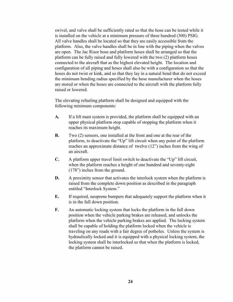
24
swivel, and valve shall be sufficiently rated so that the hose can be tested while it is installed on the vehicle at a minimum pressure of three hundred (300) PSIG. All valve handles shall be located so that they are easily accessible from the platform. Also, the valve handles shall be in line with the piping when the valves are open. The Jac Risor hose and platform hoses shall be arranged so that the platform can be fully raised and fully lowered with the two (2) platform hoses connected to the aircraft that as the highest elevated height. The location and configuration of all piping and hoses shall also be with a configuration so that the hoses do not twist or kink, and so that they lay in a natural bend that do not exceed the minimum bending radius specified by the hose manufacturer when the hoses are stored or when the hoses are connected to the aircraft with the platform fully raised or lowered. The elevating refueling platform shall be designed and equipped with the following minimum components: A. If a lift mast system is provided, the platform shall be equipped with an
upper physical platform stop capable of stopping the platform when it reaches its maximum height.
B. Two (2) sensors, one installed at the front and one at the rear of the platform, to deactivate the “Up” lift circuit when any point of the platform reaches an approximate distance of twelve (12”) inches from the wing of an aircraft.
C. A platform upper travel limit switch to deactivate the “Up” lift circuit, when the platform reaches a height of one hundred and seventy-eight (178”) inches from the ground.
D. A proximity sensor that activates the interlock system when the platform is raised from the complete down position as described in the paragraph entitled “Interlock System.”
E. If required, neoprene bumpers that adequately support the platform when it is in the full down position.
F. An automatic locking system that locks the platform in the full down position when the vehicle parking brakes are released, and unlocks the platform when the vehicle parking brakes are applied. The locking system shall be capable of holding the platform locked when the vehicle is traveling on any roads with a fair degree of potholes. Unless the system is hydraulically locked and it is equipped with a physical locking system, the locking system shall be interlocked so that when the platform is locked, the platform cannot be raised.

25
G. A hose and cable carrier that contains and guides all platform hoses and electrical lines that move with movement of the platform. The carrier shall be an open plastic type of sufficient size to handle all lines and to properly guide all lines when the platform is elevated to any height.
H. A mechanical safety latch that can be utilized to prevent the lift from lowering from an elevated height that allows maintenance to be performed beneath the lift platform.
The platform hydraulic system shall function from a twelve (12) VDC power supplied from the vehicle’s master electrical switch. The system shall include all necessary components properly rated for the type of service. The hydraulic reservoir, pump/motor assembly, solenoids, relays, etc. shall be located near the cab, in a protected area and deemed as part of the engine compartment, easily accessible for servicing. The reservoir shall be equipped with a drain ball valve and chained plug. The bottom of the hydraulic cylinder shall be securely bolted to its supporting structure and the fluid port shall be equipped with an adjustable flow valve with lock to control and set the up/down speed of the platform. The top of the cylinder shall be enclosed to prevent any water from reaching the cylinder head. The hydraulic system shall be equipped with two (2) emergency lowering valves that lower the platform by returning hydraulic oil from the lift cylinder to the reservoir, in event of an electrical failure or emergency. One (1) emergency lowering valve shall be a push/pull type and shall have a weather-proof boot, and shall be located at the highest point on top of the platform panel so that it can be vertically activated. The second emergency lowering valve shall be a brass ball valve located in a position that is easily accessible from the ground. Either valve shall be capable of lowering the platform. The platform shall be equipped with a spring-loaded single momentary control switches to raise and to lower the platform. Each switch shall be a Cole Hersee model M-490 in a sealed enclosure. The switch assembly shall be located at the upper right side of the platform panel. A second switch to raise the platform shall be installed in an inconspicuous location so that it is accessible from the ground to perform maintenance. The switches shall be vapor-proof and have Class 1 Division 2 ratings. The platform electrical system shall function off the vehicle’s master electrical shutoff switch. The system shall include all necessary components properly classified and rated for the type of service. All solenoids, relays, fuses, circuit breakers, electrical connections, etc. shall be located near the cab, in a weatherproof electrical box located in a protected area, easily accessible for servicing.

26
The platform shall be equipped with access steps located on the left side of the vehicle to provide access onto the platform’s entrance gate. The access steps shall have a minimum of eighteen (18”) inches wide Ryerson Morton Grip Strut steps. The steps shall be equally spaced approximately ten (10”) inches apart and the first step shall not be more than eighteen (18”) inches above the ground. The steps shall be designed to support a minimum of five hundred (500) pounds. A handrail fabricated from one (1”) inch pipe shall be provided and installed on both sides of the access steps. All steps, stairways, ladders walkways handholds, handrails, and used to access the cab, maintenance and operational areas or other parts of the equipment shall also minimally conform to the most recent edition of SAE J185 – Access Systems for Off-Road Machines, using the ‘preferred’ dimensions offered in this standard.
28. Elevating Refueling Platform Equipment The refueling platform shall be equipped with all required components to perform the aircraft refueling operation, and shall also include the following minimum items: A. A digital fuel pressure display as described in paragraph entitled “Digital
Pressure Control System Requirements,” subparagraph entitled “Refueling Nozzle Pressure Display.” The display shall be installed at a location that is readily visible by the operator. The display shall be protected by a one half (½”) inch thick Lexan bolt-on cover.
B. A deadman line and control of sufficient length to allow operation of the refueling system on the platform as specified in the paragraph entitled “Deadman” to activate/deactivate the aircraft refueling control system.
C. Storage for the deadman control.
D. Two and one half (2½”) inch refueling hoses as specified in the paragraph entitled “Refueling Hoses” subparagraph entitled “Refueling Platform.” Each refueling hose shall be connected to the platform supply pipe and shall be equipped with an underwing refueling nozzle as specified in the paragraph entitled “Underwing Nozzles.”
E. Two underwing nozzle storage holders as specified in the paragraph entitled “Underwing Nozzle Storage Holders.” The holders shall be positioned so that the refueling hoses lay in a natural bend so that the hoses are not susceptible to kinks as specified herein.
F. An emergency refueling system shutdown valve located so that it is readily accessible to the operator.
G. Stainless steel brackets and rollers if required to protect hoses.
27
H. A Betts model 305B-07113 spot light with switch shall be installed on the elevating platform.
29. Product Tank
The tank shall have a nominal capacity of 10,000 U.S. Gallons. The actual capacity of the tank shall be determined by the Contractor to provide the capability of the vehicle to dispense a minimum of 9,800 U.S. Gallon with a full tank, while having the additional capacity required for fuel expansion and for sump and low fuel level allowances. The complete tank including all components and hardware shall be of 300-Series stainless steel. The tank shall be constructed throughout of ASTM 304 E.L.C. B2 finish stainless steel. The complete tank shall be designed and constructed so that it meets all DOT 406 latest requirements as specified by 49CFR178.346. The tank shall also be tested to the DOT 406 requirements and a certificate of compliance shall be provided certifying that the tank meets all the latest DOT 406 construction and test requirements. The tank shall also comply with all the requirements stipulated in the aforementioned Port Authority "Airport Rules And Regulations." Documents of all tests and certificates of compliance shall be provided to the Engineer. The Contractor shall provide a product tank with a warranty for the tank to satisfactorily operate without any leaks for a minimum period of ten (10) years, starting from the time the vehicle is placed in-service. The tank shall have a maximum overall width of one hundred and twenty (120”) inches, and an adequate height and length to provide a vehicle that has the proper weight distribution and a center of gravity that is as low as possible. The tank shall have a semi-rectangular cross section with rounded corners and shall be of smooth skin construction. The tank shall be designed as a single compartment tank with the required reinforced heads, baffles, stiffeners, and reinforcements. Where reference is made throughout the specification to a tank compartment, it shall mean the area of the tank between baffles. The tank bottom and extending a minimum of 8 inches above the outriggers shall be of a minimum thickness of eight (8) gauge material. The tank sides, top, baffles, and all other structures of the tank shall be of a minimum thickness of ten (10) gauge material. The front and rear tank heads and all baffles shall have flanged and dished type configuration, and shall also have channel stiffening members. Dimpled tank heads are not acceptable. The Contractor shall use SAE 347 alloy stainless rod to weld all material together. All exterior welds shall be smooth and clean. The tank shall be provided with the required continuously open trough at the bottom of the tank to provide the required sump area to collect water. The trough shall be an integral part of the bottom tank shell, and shall have a minimum size
28
of four (4”) inches wide at the bottom and run the full length of the tank. The tank shall be equipped with three (3) bottom drain valves installed at the center of the trough as specified in the paragraph entitled “Tank Water Drain System,” that will fully drain the product tank. One valve shall be located at each end of the tank and one shall be located at the center of the tank. The tank bottom including the trough shall be designed and constructed so that it meets all DOT 406 requirements. The tank shall be equipped with a heavy duty integral tank frame as specified in the paragraph entitled “Tank Frame.” The tank shall be properly assembled onto the chassis with all proper components to provide satisfactory service including withstanding all imposed stress and flexing loads during all modes of operation. A strapping chart measured in one quarter (1/4”) inch increments shall be furnished and provided in the manuals. The tank interiors shall be clean and free of scale, rust and water and shall be flushed with jet fuel prior to delivery. The tank shall only be tested with clean jet fuel that meets ASTM D1655 specifications when filled to perform all vehicle performance tests. All screens, strainers, filters, and accessories shall be cleaned after completion of all tests.
30. Tank Frame The tank shall have a longitudinal structure welded directly to the bottom of the tank, forming a tank frame that provides sufficient structural integrity and support of the tank when installed onto the chassis, to provide satisfactory service including withstanding all imposed stress and flexing loads during all modes of operation. The tank frame shall be of a proper design configuration and width for satisfactory performance. The tank frame shall extend approximately four (4”) inches longer than the tank at both the front and the rear heads of the tank, and each extension have gussets that connect to the head stiffening members. The frame shall be completely fabricated from a minimum thickness of three eighths (3/8”) inch 300-Series stainless steel and shall be full section from front to rear. The frame shall be reinforced with all necessary supports, gussets, cross members, etc. necessary to distribute concentrated loads over large areas, withstand all bending and torsional stresses in all operating conditions. The tank shall be installed on a chassis frame using standard industry practices for installation of large fuel tanks on chassis. The tank shall be secured to the chassis by suitable hold-down devices, using Grade-8 bolts, washers, and nuts. All nuts shall be elastic self locking type nuts. A full length sill shall be installed between the tank frame and the chassis frame. The frame shall be equipped with a C-

29
Section of sufficient size that runs the full length of the tank frame to enclose and secure the tank sill to prevent it from moving or slipping out. If the tank is a detachable component of the vehicle, as a trailer type design, the tank shall have a frame equipped with additional structural framework as required to install all other components required, such as, fifth wheels, trailer axle and suspension system(s), etc. and all other components required for the proper operation of the vehicle. The tank shall be secured to the axle and suspension system(s) by suitable design, using Grade-8 bolts, washers, and nuts. All nuts shall be elastic self locking type nuts.
31. Tank Rollover Protection The top of the tank shall have a structural rollover protection rails of proper height and configuration. The rollover rails shall be fabricated from a minimum size of three (3”) inch stainless steel structural tubing that run the full length of the tank and be adequately anchored as an integral component to the tank heads and bulkhead structure. The rollover protection rails shall be designed and installed so that they protect the manhole covers, vents, and all other components installed on the top of the tank and it shall be elevated from the top of the tank so that rain, snow, and sleet can runoff the sides of the tank. The front of the tank shall be equipped with a solid protective stainless steel barrier section that is the height of the rollover rail and with sides that flare outwards approximately three (3’) feet toward the rear and sides of the tank so that any product spills from the top of the tank does not drain towards the front head of the tank but can drain towards the rear of the vehicle. The complete tank rollover protection shall be manufactured from 300-Series stainless steel. A one (1”) inch clear synflex drain line shall be provided on the bottom corners on each side of the front section and run from the top to approximately six (6”) inches below the frame rails, to control the draining of liquids from the top front area of the tank. Each drain line shall be properly secured. The rollover supporting structure shall be designed to fully protect the tank and all components on the top of the tank from damage in the event the vehicle overturns. The top of the rollover structure shall have a minimum clearance of one and one half (1½”) inch above the highest point of any component installed on the top of the tank. The complete rollover structure shall be in compliance with DOT 406 requirements.

30
32. Tank Top Walkway The top of tank shall have a walking area that is between the two (2) rollover rails, and have 300-Series stainless steel expanded metal walkway areas between the manhole covers. The walkway shall be a minimum of thirty (30”) inches wide, run the full length of the tank. Any area on the walkway shall meet walking areas as required by OSHA requirements and be capable of supporting a six hundred (600) pound load without experiencing any permanent deformation. All open edges shall be ground smooth and there shall be minimum projections. The Contractor shall design and install a one (1”) inch stainless steel pipe on the inside and on each side of the tank rollover protection rails that run the full length of the tank for use as a walkway safety anchor. The walkway safety anchor is to allow a person to secure a safety harness to each side of the tank with a quick connect snap-on closed hooks and allow the person to walk down the center of the tank while the harness can slide down the pipe on each side of the tank. The Contractor shall provide six (6) safety harnesses that meet all OSHA requirements and require their use when accessing the top of the tank.
33. Tank Ladder A permanent ladder shall be provided at the center and at the rear of the tank to provide access to the top of the tank. The ladder shall be either completely secured to the tank or if secured to the tank and the chassis, it shall have flexible type joints to relieve flexing stress between the tank and the chassis. The ladder shall be of a heavy duty construction with the required supports. The ladder shall be the manufacturer’s standard production ladder. Also, a swing type stirrup step with a shear bolt that provides a step at approximately sixteen (16”) inches above the ground shall be bolted under the bumper to provide a step to access the rear ladder. Grab-handles shall be provided on the top of the tank on each side on the inside of the ladder to provide safety of ascent and descent. All steps, stairways, ladders walkways handholds, handrails, and used to access the cab, maintenance and operational areas or other parts of the equipment shall conform to the latest edition of SAE J185 – Access Systems For Off-Road Machines, using the ‘preferred’ dimensions offered in this standard. This requirement shall apply to all steps, stairways, ladders walkways handholds, handrails, and access locations specified throughout these specifications.

31
34. Tank Manholes The tank shall be equipped with one (1) manhole opening at the center of each compartment. All manhole openings shall be twenty (20”) inch diameter. Three (3) manhole openings shall be equipped with hinged covers. The manholes with the hinged covers shall be located one (1) on the front compartment, one (1) on the center compartment, and one (1) on the rear compartment. All other compartments shall be equipped with blank, inspection type, manhole covers. The hinged manhole covers shall be Tiona Betts model that meets the latest DOT 406 requirements. The cover shall be installed so that the hinges are located at the forward end of the vehicle, so that the covers close when the truck moves forward. The manhole assembly shall be 304 stainless steel twenty (20”) inch with ten (10”) inch hinged fill covers of the self closing and latching type. The manhole cover and vents shall not be obstructed and they shall conform to the latest DOT 406 requirements. The blank manhole covers shall be 304 stainless steel twenty (20”) inch Tiona Betts inspection manhole covers. All manhole cover gaskets shall be of a material approved for use with aviation fuels. All vents shall be equipped with fire screens. The three (3) compartments that have the hinged manhole covers shall have a circular disc gauge marker on a threaded stainless steel rod with provision for a safety locking seal. The discs shall be set at the proper height marking the maximum level to fill the tank providing adequate provision for expansion.
35. Product Tank Digital Level Gauge System The product tank shall be equipped with an intrinsically safe product tank digital level gauge and display system to indicate the quantity of product in the tank. The product tank digital level gauge and display system shall be a Titan Logix Corp model TD 80-CBEXT, with the Finch 5332E Display, completely rated for Class 1 Division 2 hazardous area application, and with programmable low, high, and high-high alarms. The level gauge and display system shall be installed at the approximately the center of the tank, where it can provide the best product level reading, and installed in accordance with the manufacturer’s requirements, so that it can be programmed to accurately operate in the vehicle. The level gauge system shall be programmed by storing a product tank strapping chart by the method required by the manufacturer. The display shall provide a readout in whole gallons for the quantity of product in the tank.

32
The digital display gauge shall also be setup to shutdown the refueling system by disabling the deadman when the quantity of fuel in the product tank reaches a level that prevents any air from being injested from the internal valve when discharging the tank and allows the deadman to be operational when the refueling system is set for defueling. The product tank digital level display shall be installed on the control panel and easily visible from the side of the vehicle.
36. Equipment Rack Equipment racks shall be provided on the vehicle to support and protect all components. The equipment racks shall be of a heavy duty structural construction, capable of supporting all required components. The equipment rack support frame shall be fabricated from heavy wall structural members with all necessary cross members, diagonals, gussets, brackets, and mounting plates. All enclosures or splash plates or shields shall be provided to protect the components. All racks shall be properly installed and located so that they provide the best maintenance accessibility to all components. The location of all equipment racks shall also be selected to achieve the proper vehicle weight distribution. Any rack and all components installed on it shall provide a minimum of fourteen (14) inches of ground clearance with a fully loaded vehicle. The equipment rack(s) shall also have all necessary lighting for the fueling operation and marker lights.
37. Internal Valves And Venting System The product tank shall have a Carter model 64247 6-inch internal valve with proximity switch and a Carter model 64220 five and one quarter (5¼”) inch tank vent valve with proximity switch. The vent valve shall be operationally interlocked so that the internal valve does not open until the vent valve is first opened. This sequence operation shall occur when the vehicle is set to fuel or defuel aircraft, or set to be bottom loaded or top loaded. The system shall be designed, assembled, and operated with the required internal valves, venting and pressure relief systems required to comply with all requirements specified by 49CFR178.346 and NFPA 407. The construction of all valves and their components shall be 300-Series stainless steel or aluminum. The construction of all brackets, supports, hardware, etc. shall be 300-Series stainless steel. All internal and vent valves shall be air or fuel operated and bolted onto a TTMA flange welded to the tank shell. The seat opening on the internal valve shall be a minimum of two (2”) inches above the lowest point measured from the bottom of the tank shell to provide the area

33
required to trap water. All vents shall be equipped with fire screens to control flame propagation. All components shall be properly protected and arranged so that they can be serviced and removed through the manhole opening, or removed from the exterior of the product tank. Each vent shall be equipped with a sealed cover that protects the valve and prevents water from rain or snow to collect on the top of the valve. The vent shall be equipped with a hood type cover that connects into to the tank rollover tube or other piping that allows the product tank to vent to the right side and rear of the vehicle. The venting system shall be designed so it only vents toward the rear of the vehicle from the connecting point. The discharge end of the vent shall be equipped with a forty-five (45) degree elbow with a removable screen that is installed with a Victaulic connection that directs the vent towards the rear and in the downward direction. To load the truck from the top, only the center compartment with the hinged manhole cover shall be used and it shall be designated as the toploading compartment. The internal valve and all components installed in the toploading compartment shall be adequately protected from the fill tube. The product tank, internal valve, and venting system shall have a minimum capability of filling or pumping off the product tank at a minimum rate of 900 GPM, with all compartment liquid levels remaining relatively at an equal height. The tank shall have a properly sized tank bottom loading and product discharge piping to properly load and offload the tank through the internal valve. The bottom loading pipe shall meet the requirements specified below. The product discharge pipe shall have a vertically mounted sump, installed at the lowest point of the tank drain and fill pipes. The tank discharge pipe shall be a minimum size of six (6”) inches, connected from a higher point above the product tank sump to the product pump. A posi-seal six (6”) inch butterfly valve shall be installed in the tank discharge pipe and easily accessible from the side of the vehicle with a provision to lock the valve handle when the valve is off.
38. Tank Water Drain System All product tank and other sumps shall be fitted with an internal water drain system consisting of a screw-in type, one (1”) inch drain valve, Morrison model 372-0200AV operated with a cable operator. The valve shall be equipped with a stainless steel screen on the inside of the sump. The cable operated valves shall be designed with a spring loaded positive shut-off system, so that the valve will self-close and remain closed unless the cable is pulled to hold the valve open. The

34
tank drainage system shall be designed, assembled, and operate so that it meets all requirements specified 49CFR178.346. The cable operated valves shall be connected to manually operated three quarter (¾”) inch full-flow drain ball valves using a minimum size of three quarter (¾”) inch copper or stainless steel tubing. The drain valve handles shall not be less than three (3”) inches long. The discharge shall be fitted with a brass street elbow facing down with a three (3”) inch long brass pipe nipple with an Evertight male fitting with a cap that is secured to the vehicle with a braided cable. The drain ball valves shall be grouped together in an approved location, guarded so that they are protected from breakage, and properly labeled. Each compartment and valve assembly shall be arranged so that no water pockets can form.
39. Bottom Loading/Test Recirculation System The vehicle shall be equipped with two (2) bottom loading connections located on the left side of the vehicle and at the front end of the product tank. These connections shall also be used for recirculating and testing the refueling system at a minimum rate of 800 GPM. These two (2) connections shall be located so that the two (2) elevating platform hoses, ground fueling hose, or bottom loading hose(s) can easily be connected from the ground position. The system shall meet all SAE AS1284, ARP5818, and ARP5918 latest requirements. Each fill connection shall be equipped with a two and one half (2½”) inch Carter or Meggitt bottom loading adapter with cap and a two and one half (2½”) inch posi-seal butterfly valve. The two (2) connections with the valves shall be piped downstream into a manifold that is piped into a four (4”) inch electrically operated butterfly valve, a four (4”) inch gate valve, and into the product tank. A gammon quick connect with cover shall be located in the manifold upstream of the electrically operated butterfly valve where a calibrated fuel gauge can be connected to perform aircraft refueling system tests. The complete system shall be designed to have the minimum capability of handling Jet-A fuel at a minimum flow rate of 800 GPM. The gate valve shall be used to make back pressure adjustments when testing the refueling system. The electrically operated butterfly valve shall be used to perform surge tests and to stop tank filling operations when the tank is full as signaled by the Scully system as described in paragraph entitled “Product Tank High-Level Shutdown System” and to perform surge tests when testing the aircraft refueling system. The four (4”) inch gate valve shall be a Betts model AAG1014 aluminum gate valve with a wheel handle. The electrically operated butterfly valve shall be a Flowseal high performance four (4”) inch 316 stainless steel wafer valve with a GE RCS electric actuator model DCR 50-2, operated with twelve (12) VDC and

35
rated for the application. Electric actuator shall be equipped with a heater to eliminate any condensation, a brake, all required auxiliary limit switches, and any other components control systems required to operate as specified herein. The electrically operated butterfly valve shall also be equipped with an indicator that shows the position of the valve and the ability to override the valve. The valve shall automatically revert back to the proper operating positions when the manual override is operated and the electric operator is cycled. The valve shall operate by a control system shall utilizes a motor driver to set the speed to close the valve. The motor driver shall be equipped with two potentiometers where each can set the closing speed of the valve. A valve shutoff speed selector switch shall be provided, and it shall be a SPDT switch that shall be used to select either potentiometer to close the valve. One potentiometer shall be set to close the valve from full open to full close in two (2) seconds or less and the other potentiometer shall be set to close the valve from full open to full close in five (5) seconds or less. The valve shall be operated by a momentary switch that closes the valve in the closing time when the switch is activated. A test panel shall be provided and it shall be equipped with the following components to perform aircraft refueling system tests:
Valve speed selector switch
Valve shutoff switch
Pressure gauge to indicate system back pressure and surge pressure
All wiring and system components shall meet all NFPA 406 and NEC requirements. A quick disconnect shall be installed in the manifold upstream of the gate valve that will be used to install a calibrated pressure gauge to check pressure reading when performing refueling tests. The manifold shall be piped into the product tank, and routed to the bottom of the tank with a check valve, an aluminum or stainless steel diffuser, and all other required components to fill the product tank and meet all DOT 406 certification requirements. The bottom loading/test recirculation system shall be equipped with an interlock system that automatically applies the parking brakes when any hose(s) are connected.
40. Product Tank High-Level Shutdown System The product tank shall be equipped with a primary and secondary high-level shutdown systems to safeguard the product tank from overfilling during any bottom loading operations or aircraft defueling operations. Each system shall be equipped with all necessary components, sensors, operators, indicators, and test

36
devices to assure their operation. Each shutdown system shall be installed as per manufacturer’ recommended installation requirements. The shutdown system shall be equipped with a Scully Intellicheck 2 overfill and monitoring system model 08961SHO, setup for aviation aircraft refueling tanker vehicle operations. The system shall be equipped with a Scully thermosocket model 08678. The thermosocket shall be installed in a location near the bottom loading connections to connect the vehicle’s Scully system to the load rack, to provide the necessary signals to/from the load rack’s control systems. The system shall be equipped with two (2) Scully 2-wire optic sensors, model SP-TO. The sensors shall be rated to operate from -40F To 140F. The high-level shutdown system sensors shall be located in the center compartment where they can best operate for sensing tank level and be readily accessible for checking and maintenance from the top of the tank, and labeled “Primary” and “Secondary,” respectively. Each sensor system shall be designed and installed to operate as follows: A. Primary High Level Shutdown System
One (1) sensor shall be of proper length so that it operates as the primary high level shutdown. The primary shutdown system shall shutdown the tank loading operation when the fuel level in the product tank reaches a predetermined level that is approximately one hundred (100) gallons lower than the full-level marker as described in paragraph entitled “Tank Manholes.” The primary shutdown system shall shutdown the tank loading operation by closing the electrically operated butterfly valve during bottom loading operations or by closing the product tank internal valve during defueling operations.
B. Secondary High-High Level Shutdown System
A second sensor shall be of proper length so that it operates as the secondary high-high level shutdown. The secondary shutdown system shall shutdown the tank loading operation when the fuel level in the product tank reaches a level that is within a maximum of one hundred (100) gallons more than the primary high level shutdown listed above.

37
The secondary shutdown system shall shutdown the tank loading operation by closing the tank load rack during bottom loading operations or by closing the product tank internal valve during defueling operations.
When the Scully system shuts down the loading operation, the following refueling system components shall operate as follows:
Deactivate the deadman
Close the product tank internal valve
Open the primary (bypass) valve
Close the secondary (in-line valve)
Revert the fuel/defuel valve to the fueling position
The primary and secondary systems shall be equipped with a pre-check system to check that the system properly operates.
41. Fuel Delivery System: General The following minimum components shall be supplied for the fuel delivery system. The Contractor shall supply and properly install all necessary components for the pumping system. The components shall function to provide the most effective, efficient, and easiest maintainable pumping system. However, notwithstanding the fact that these specifications do not call out all the details of the pumping system, the Contractor shall furnish and install a complete pumping system capable of driving the fueling pump to deliver eight hundred (800) GPM at one hundred (100) PSIG. The Contractor shall furnish, in accordance with the provisions of the clause entitled "Contractor's Drawings," a detailed drawing of such pump drive, including make and model of components. The drive mechanism components shall be adequately sized for continuous service at eight hundred (800) GPM, under the most severe operating conditions.
42. Split-Shaft PTO/Pump Fuel Delivery System A. Split-Shaft PTO/Product Pump
The Contractor shall provide a complete operating pumping system that is automatically controlled from a control on the dash and interlocked to operate as specified herein. The system shall include a shift system, split shaft driven, self priming centrifugal product pump, Gorman-Rupp model 06D3-GHH ductile iron pump with heavy duty gear box and shift to engage the pump and capable of delivering a minimum of seven hundred and fifty (750) GPM at one hundred (100) PSIG.

38
The Contractor shall install all components to activate and transmit power from the truck chassis driveline to the PTO that drives the product pump. The pumping system shall be installed and function as per manufacturer's recommendations. The system shall include the power take-off, drive shafts, activating and deactivating components, interlock components, and all other required components necessary for the proper operation. The pumping system shall properly function through the neutral safety switch, utilizing a throttle stop and the min/max governor control system. The PTO actuating system shall be equipped with a proximity switch that indicates positive engagement and disengagement of the pump. The system shall be simple, and utilize the minimum amount of valves and switches. The PTO shall power the product pump through a proper sequence actuating system. The system shall insure that the vehicle's driveline is completely stopped before shifting into the pump mode and the driveline is stopped or rotating at a speed that is within the manufacturers requirements before shifting into gear. The parking brake shall apply automatically when the PTO system is engaged, and function as part of the interlock system. The system shall also be properly interlocked to function smooth and as described in the paragraph entitled "Interlock System." The actuating system shall be fully designed to function in a fail-safe manner under all conditions. The control to activate the pump system shall be installed in the cab in a location convenient for the driver's control. An indicator light shall be installed in the cab near the control and a second indicator light shall be installed on the control panel. The PTO and product pump shall be installed in a quality manner and in accordance with the manufacturer’s requirements. All necessary components requiring modification or fabrication shall be performed in a quality manner to provide maximum durability. Standard off-the-shelf components shall be used as much as possible. All required additional supports, gussets, and reinforcements shall be provided and properly installed. All frame modifications shall be properly done according to standard industry practices.
B. Product Pump Piping The pump suction and discharge lines shall be properly piped from the tank to the dispensing equipment and other components, with proper size pipes. The piping system assembly to the pump shall be designed and installed so that it complies with all manufacturer’s recommended

39
requirements. All connections to the pump or through bulkheads shall be made using Victaulic or flange type couplings. The piping system shall be designed with properly routed pipes and swivel joint assemblies, which shall provide maximum flexibility and necessary movement between the cab-chassis, the tank, and the equipment. The piping shall incorporate all requirements set forth in the paragraph entitled "Piping, Fittings, & Valves", and required by 49CFR178.346, NFPA 407, and the Port Authority Airport Rules And Regulations. The pump installation and piping design shall take into consideration component stress, vertical, horizontal, and torsional loads, flotation, lubrication, maintainability, and facilitate removal and installation of both the pipe sections and the components.
43. Piping, Fittings, Valves & Swivels
A. Main Product Fuel System
The fuel product shall be handled through a system of rigid piping joined together by welding, Victaulic, and flanged fittings with proper gaskets and seals. All gaskets and seals shall be of a material approved for use with aviation fuels. All system piping shall meet the minimum requirements as listed in SAE ARP5818. All fittings with the pipe threads shall be coated with the proper sealant(s) required to handle jet fuels. All components, piping, and fittings shall be rated for the working pressure of the system. The piping system and each section shall also be designed to limit the fuel velocity to a safe level, when operating at maximum flow conditions as stipulated in SAE ARP5818. To provide optimum cleanliness of fuel, all piping, fittings, valves, strainers, control system components, and all other piping system components in contact with the fuel product upstream and downstream of the filter-separator shall be stainless steel or aluminum. All stainless steel fittings shall be Best Weld fittings. In addition, all components with alloys that come into contact with the jet fuel product dispensed, shall be free of copper, brass, lead, and zinc. At least one (1) Victaulic coupling shall be installed in selected locations of the piping system to act as vibration dampeners and to facilitate maintenance. Victaulic nipples shall be made of thick wall and installed as recommended by the manufacturer. The shoulders of Victaulic nipples shall be flush with the inside of adjacent piping. All aluminum pipe

40
flanges shall have a minimum thickness of one half (½”) inch. Flanges shall not distort when bolts are tightened to their proper torque requirements. All flange connections shall have the proper gaskets. All shut-off valves shall be Norris butterfly type, provided with Viton (Hycar) seat and seals, stainless steel stem, and detent stops. All valves shall be assembled so that the valve is open when the handle is in-line with the piping. Unless otherwise stated, all seals used in all components throughout the system shall be Viton seals. All piping, valves, flanges, fittings, components, etc. shall conform to the best practices of the industry and shall be selected for minimum pressure loss. The piping and complete system shall only be tested with clean jet fuel that meets ASTM D1655 specifications.
B. Swivels Handling Product
All swivel joints, except nozzle swivels or other as specified within these specifications, shall be OPW Endura swivel joints with the required eccentric tolerance to provide reliable service for the specific application where the swivel is installed. Each swivel joint shall be of the proper size, style, and rating for the application (including testing of the hoses) and be installed in accordance with the manufacturer’s requirements and also installed so that it is easily accessible for disassembly to inspect, replace, or perform maintenance without removing any major piping from the vehicle. The piping and swivels shall be installed so that they operate within the eccentric tolerance of the swivel and without undue wear.
C. Pneumatic Systems All air lines shall be heavy wall synflex tubing. The lines shall be full length (from component to component), properly and neatly routed and supported. All air lines, fittings and components shall be sized for minimum friction loss and properly function as required. The valves shall be properly selected and rated for its service. All air valves, lines, and components shall operate without failure from -20F To +120F, and shall have a minimum rating of two hundred (200) PSIG working pressure.

41
D. Fuel Control Lines, Sump Drains, And Fuel Systems Components
All fuel control and sense lines that handle product shall be stainless steel with all stainless steel fittings, valves, and components. All components, piping, and fittings shall have a minimum rating of one hundred and fifty (150) PSIG working pressure. The lines shall be full length (from component to component) or as practical for installation and maintenance, properly and neatly routed and supported. All lines, fittings and components shall be sized for minimum friction loss and shall properly function as required. All fuel control line fittings shall be threaded type fittings and all sump drain line fittings shall be either threaded or shall have compression ferrules and fitting nuts. All components shall be properly selected and rated for its service and shall operate without failure from -20F To +120F.
E. Sump Drains
All drain lines shall be either copper or stainless steel. All drain lines shall be equipped with brass or stainless steel fittings, valves, and components. All sump drains shall be equipped with spring-loaded shutoff valves that remain fully closed in the normal position. The end of all drain discharges of each drain line shall be equipped with fitting that direct flow to the ground direction and the end of the drain line shall be equipped with a three quarter (¾”) inch quick disconnect OPW male Kamlok adapter with a female dust cap that is secured to the vehicle with a cable.
44. Filter-Separator/Monitor
The refueling system shall be equipped with a horizontal three (3) stage filter-separator/monitor vessel. The filter-separator shall be a micronic filter-water separator unit with coalescing filter elements and teflon separators. The three (3) stage filter-separator/monitor vessel shall be installed so that all fuel dispensed from any refueling nozzle flows through the vessel. The filter-separator/monitor vessel shall be located on a structural support framework, positioned to provide best accessibility for element servicing and maintenance. The filter-separator/monitor shall be a Velcon or Facet model equipped with the latest EI approved coalescing filter elements, separators, and monitor elements. The filter-separator/monitor unit shall be rated at a minimum of eight hundred (800) GPM for Jet-A fuel and shall be capable of removing solid contaminants of 0.5 microns and one hundred percent (100%) water in accordance with EI 1581 latest edition for operation in an aircraft refueling vehicle.

42
The filter-separator/monitor vessel shall be provided complete with all new coalescing filter elements, separators, and monitor elements, and, all brackets and hardware for each vehicle as required herein and shall be certified to have passed the latest performance requirements of EI 1581 and EI 1583 latest editions for operation in an aircraft refueling vehicles. A letter shall be furnished certifying that the filter-separator/monitor operates in accordance with the aforementioned performance requirements and provide all other documentation as requested by the Engineer. The filter-separator/monitor vessel shall be of aluminum or carbon steel construction, be designed and labeled in accordance with ASME code, and have a rated working pressure of one hundred and fifty (150) PSIG, tested to two hundred and twenty-five (225) PSIG. The vessel shall have a label affixed to the vessel with the manufacturers' U1-A label. The filter-separator/monitor vessel shall have a hinged end opening cover with swing bolt that secures the cover and Buna-N o-ring sealing gasket. Carbon steel vessels shall be internally epoxy coated to MIL-C-4556D. The hinged cover shall remain level when opened and shall be properly positioned to secure in place when closed. The filter vessel shall also have changeable screw bases. All piping and components installed in the filter-separator/monitor shall be made of non-corrosive materials. A drain valve as specified in the paragraph entitled “Filter-Separator Water Sump Control Valve” shall be provided for draining the filter-separator sump. The filter-separator/monitor vessel shall be equipped with the following minimum components: A. Pressure Relief Valve: To prevent excessive fuel pressure build up
including fuel pressure built up from thermal expansion to be automatically relieved from the filter-separator/monitor and refueling system to the product tank. The relief valve shall be installed at the top of the filter-separator/monitor.
B. Air Eliminator: To automatically eliminate air from the filter-separator/monitor vessel and refueling system relieving it to the product tank. The air eliminator shall be a stainless steel or carbon steel Armstrong Machine Works model 21 air trap. The air eliminator shall be installed at the top of the filter/separator/monitor vessel and shall be piped to the product tank to vent all air, and shall be installed so that any release of fuel will not splash, spray or free fall.
43
C. Vacuum Breaker: To facilitate draining and sumping the filter-separator/monitor vessel. The vacuum breaker shall be a Gammon model GTP-9365, installed at the top of the filter-separator.
D. Filter-Separator Differential Pressure Gauge: To indicate the differential pressure across the filter-separator elements. The gauge shall be a Gammon Technical Products model GTP-534-PBF-30A. The gauge shall be equipped with a full deflection test button or valve, and it shall be located on the control panel. The gauge shall be equipped with plugged connections to allow easy installation of an external differential pressure gauge to indicate the differential pressure across the monitor elements.
E. Monitor Differential Pressure Gauge: To indicate the differential pressure across the monitor elements. The gauge shall be a Gammon Technical Products model GTP-534-PBF-30A. The gauge shall be equipped with a full deflection test button or valve, and it shall be located on the control panel. The gauge shall be equipped with plugged connections to allow easy installation of an external differential pressure gauge to indicate the differential pressure across the monitor elements.
F. Filter Elements: The new coalescer, separator, and monitor elements shall not be installed, and they shall all be provided new with all the proper installation brackets and hardware, all packaged and shipped with the vehicle for installation at the Airport. All the packages shall be marked with the vehicle number.
G. Water Drain Valve: To drain the filter-separator/monitor sump, as described in the paragraph entitled “Filter-Separator Water Sump Control Valve.”
H. Filter-Separator High Differential Pressure Shutdown: A differential pressure system that shuts down the refueling system when the differential pressure across the filter-separator is exceeded and shall illuminate a red indicator light on the control panel to show that the system was shut down due to a high filter-separator differential pressure. The Filter-Separator Differential Pressure Gauge test button shall be used to test the shutdown feature. The refueling system shall operate so that when it is shutdown by the high differential pressure shutdown, it shall trigger a latching relay and remain disabled until it is reset by a Filter-Separator High Differential Pressure Shutdown Reset Switch located in the locked compartment as listed in the paragraph entitled “Control Panel.”
I. Monitor High Differential Pressure Shutdown: A differential pressure system that shuts down the refueling system when the differential pressure across the monitor is exceeded and shall illuminate a red indicator light on the control panel to show that the system was shut down due to a high

44
differential pressure. The Monitor Differential Pressure Gauge test button shall be used to test the shutdown feature. The refueling system shall operate so that when it is shutdown by the high differential pressure shutdown, it shall trigger a latching relay and remain disabled until it is reset by a Monitor High Differential Pressure Shutdown Reset Switch located in the locked compartment as listed in the paragraph entitled “Control Panel.”
Each vehicle shall be provided with a new set of all filtration system elements as specified above, all packaged for best protection and shipped with the vehicle. However, the Contractor shall have one set of filter elements to test all vehicles as specified in the paragraph entitled “Refueling System Testing.”
45. Filter-Separator Water Sump Control Valve The filter-separator shall be equipped with an electronic operating water sump control, Gammon Technical Products model GTP-9330 1-CC Water Probe latest production model for water detection, equipped with the recommended control system with adequate enclosure and operating controls for the application, installed at the bottom of the filter-separator sump. The water sump control valve system shall function to automatically stop the refueling system and prevent the flow of fuel to the aircraft and deactivate all deadman valves whenever there is an accumulation not exceeding three (3) quarts of water in the sump. Fuel overshoot upon shutdown shall not exceed five percent (5% ) of flow. The sump control system shall incorporate an externally manually operated pre-check test to assure that the shutdown system is properly working when the refueling system is either stopped or operating at full flow conditions. A minimum size of three quarter (¾”) inch stainless steel or copper line with a manually operated three quarter ( ¾”) inch full-flow ball valve shall be provided to drain the filter-separator sump. The discharge from the sump drain valve shall be routed to a convenient location for manual draining and shall be clearly labeled. The end of the drain line shall be equipped with fitting that direct flow to the ground direction and the end of the drain line shall be equipped with a three quarter (¾”) inch quick disconnect OPW male Kamlok adapter with a female dust cap that is secured to the vehicle with a cable.
46. Clean Sample And Millipore Adapter A Gammon Sampling Kit 1, Gammon Model GTP-144, stainless steel, complete with probe, quick disconnect valve nipple, shutoff valve, and coupler shall be provided. The valve packing shall be Teflon or nylon. In no case shall the

45
packing be graphite or similar material. The coupler shall be fitted with a dust cap Gammon model GTP-1232, retained by a cable. The coupler shall be compatible with the millipore fuel test equipment connectors. Each sampling kit shall be installed on a straight section of the main refueling pipe at the following locations: Inlet side of the filter-separator vessel
Discharge side of the filter-separator vessel
The sample fittings shall be equipped with a ninety (90) degree elbow and shall run parallel to the piping. Each sampling kit shall be easily accessible and clearly identified “Inlet Fuel Sample” and “Outlet Clean Fuel Sample” respectively.
47. Water Test Device A Gammon Hydro-X Tester model No. GTP-9404 shall be provided and fully installed per manufacturer’s requirements. The tester shall be installed on the control panel and be easily accessible. The inlet shall be equipped with a shut off valve Gammon model GTP-1149-4M with a tee at the clean sample adapter. The outlet shall be connected in a section of piping down stream of the air eliminator outlet through a check valve.
48. Product Flow Meter The product flow meter shall be located downstream of the filter-separator, on the driver's side of the vehicle, near the control panel. The product meter system shall include the meter with electronic register, pre-set feature, temperature probes, fuel density meter, printer, and all other components as required to provide a complete operating system as described herein. A. Product Meter With Electronic Register Requirements
The product flow meter shall be a Liquid Controls non-ferrous model M80-2 tri-rotor aircraft refueler meter equipped with a 100:1 pulse output device that interfaces with the Liquid Controls LCR600 electronic meter register and printer. The printer shall be installed in the cab in an accessible location. The meter shall be a six (6”)_inch unit of aluminum construction with a minimum rated capacity of eight hundred (800) GPM. All parts that come in contact with the product shall be of non-corrosive material. The meter shall be accurate between fifty (50) GPM to eight hundred (800) GPM. The meter with electronic register shall be certified for conformance by A4A Specifcations 103, the National Conference on Weights and Measures, it shall be approved for use by the State of New

46
Jersey Office Of Weights And Measures, and its accuracy shall be in compliance with all applicable technical requirements of the National Institute of Standards and Technology (NIST) Handbook 44. The electronic meter register shall be UL listed for Class 1, Div 2, Groups C and D and be in full compliance with NFPA 407, Standard for Aircraft Fuel Servicing. The electronic meter register shall have the following minimum requirements: 1. Capability to display the following information:
Volume dispensed by the vehicle for each refueling job reading in large numbers in whole gallons (also capable of being set to read in tenths or hundredths of a gallon for calibration purposes). This reading shall automatically reset itself to zero (0) whenever a refueling job is initiated and before initiating a new job.
Totalizer showing the cumulative quantity of fuel dispensed by the vehicle reading in whole gallons. This reading shall be a minimum of eleven digits and it shall not be resettable.
A pre-set feature to preset a desired volume to be dispensed when performing overwing refueling reading in whole gallons.
A ten (10) character alpha numeric programmable field that allows setting a three (3) digit vehicle number that identified the vehicle and prints the set vehicle number on all printed tickets.
Messages and warnings displayed on the screen.
2. Display indication(s) that show the selected states of operation to
include delivery, emergency stop, temperature compensation, and ticket printer status, etc. Such as, in an active delivery, both the volume and flow rate are being displayed in real time.
3. LCR600 will provide an on screen message for any printer errors
4. An integral keypad with all required keys to setup, program, and operate the electronic meter register.
5. Multi-point programmable with a minimum of ten (10) points so that the meter can be programmed to automatically adjust

47
dispensing accuracy within weights and measures accuracy requirements when refueling at any rate between fifty (50) GPM and one thousand (1000) GPM. The number of calibration points and flow rates that provide the optimum performance of the meter to meet the above requirements shall be pre-determined and provided in the vehicle manuals.
6. Automatic temperature compensation with probe installed in a probe well located downstream of the meter. Capability to operate with or without temperature compensation. When temperature compensation is active, a message on the active delivery screen will read “Volume corrected to sixty (60°) degrees Fahrenheit. The temperature probe shall be calibrated either prior to the delivery of the vehicle or after delivery by the Contractor prior to the acceptance of the vehicle and the temperature compensation shall be turned "OFF."
7. Capability to store and print the following minimum data for each refueling job:
Ticket Number
Start Date and Time
Ending Date and Time
Truck Identification Number
Start Totalizer Reading in Gallons (Captured when job is initiated by activating Start on Meter)
Ending Totalizer Reading in Gallons (Captured when job is completed by activating Finish on Meter)
Total Quantity of Gallons Dispensed
Average Density
Average Temperature
Total Weight Dispensed
8. Illuminate the screen with a backlight
B. Operating Capabilities
The electronic meter register shall have the following minimum capabilities: 1. Operate with twelve (12) VDC power input with ± twenty percent
(20%) variation and have voltage spike protection induced during

48
any voltage surges, including when jump starting a vehicle, in accordance with conducted electrical transients of equipment installed on commercial vehicles fitted with twelve (12) V or twenty-four (24) V electrical systems and during dual battery jump start as per ISO 7637-2:2011 (Road vehicles -- Electrical disturbances from conduction and coupling -- Part 2: Electrical transient conduction along supply lines only).
2. Two (2) solid state outputs which are rated to twenty-eight (28) VDC for control of other operations and direct interface to a programmable logic controller (PLC).
3. Pulse output shall be fully programmable and shall be an open collector output with an internal pull-up resistor tied to a voltage input. The output voltage shall be settable to the system operating voltage.
4. An RS-232 serial communication capability for connecting an electronic ticket printer.
5. An RS-232 and RS-485 serial communication capability for interfacing with suitable on- board computing equipment.
6. The ability to customize user defined delivery tickets, formatted in English language, without changing hardware or software.
7. Multiple programmable levels of security for various levels of operation and protection.
8. Weights & Measures sealable, and in full compliance with Handbook 44 and its NTEP Certificate of Conformance.
9. Ability to store and retrieve the last two hundred (200) refueling jobs.
The meter shall be equipped with a pulser that is secured directly to the meter and adequately secured to prevent tampering and meet all regulatory codes. A vapor proof LED light with switch shall be installed near the meter register to illuminate the meter's display area. After the vehicle is delivered, the meter shall be calibrated for Jet-A fuel at Newark Liberty International Airport or JFK International Airport by a certified calibrating company, as approved by the Engineer. The Contractor shall make all arrangements for the calibration and pay all expenses.

49
C. Fuel Density Meter
The Liquid Controls M80-2 product flow meter with the LCR600 electronic meter register shall be equipped with a fuel product density meter that shall be an integral component of the product flow meter and located on the driver's side of the vehicle, near the meter in a readily viewable location. The density meter shall automatically provide the density of the fuel product dispensed as specified herein during any aircraft refueling operation. The density meter system shall operate so that it continuously samples the product during flow and electronically registers the fuel product density as the product flows through the product flow meter. The density meter system shall be equipped with all components required to operate, test, and calibrate the density meter to the specified requirements. The density meter shall have all required components to provide a complete operating system and meet all specifications and operational requirements as listed herein. The density meter shall be an Intergated Sensing Systems, Inc., MassSense MS-LDM, that is UL Listed and certified as an intrinsically safe unit for installation and operation on the aircraft refueling vehicle operating on the airport. The density meter and its complete installation shall be UL listed for Class 1, Div 2, Groups C and D and be in full compliance with NFPA 407, NEC, and all other applicable requirements. The unit shall be stainless steel and rated for operation for Jet-A fuel product. The density meter shall have the following minimum specifications and operational requirements: 1. Meter register have the setup capability for fuel density to be
turned either “On” or “Off” and display the following:
When meter register is setup with density “Off,” the meter digital display to show “Density: OFF”
When meter register is setup with density “On,” the meter digital display to show “Density: <current density> lbs/gal at <current temperature>°F”
Meter register to show “Density: Error” when the density system reports a malfunction or any other issues that deem the density to be erroneous
Meter register to show indicator that shows “Density Out of Specs” when the fuel product is outside the ASTM D1655 density range.

50
Meter register to show an indicator that shows “Density Outside Flow Range” when the product flow rate is outside the operating flow rate range
2. The average fuel density, temperature, and average flow rate shall be printed on the refueling ticket.
3. Certified for conformance with NIST and approved for use of jet fuel on aircraft refueling vehicles.
4. Operating flow rate range from eighty-five (85) GPM to eight hundred (800) GPM of product flow rate through the meter.
5. Determine and capture density, temperature, and flow rate data readings at a minimum rate of one (1) density reading per one half (½) second, each with a minimum accuracy of 0.0001 g/cc, and providing the corresponding temperature readings that has a minimum accuracy of 0.6°F, throughout the operating product flow rate range.
6. Ability to display density in lbs/gal and temperature in °F, and also the average corrected density at standard temperature for each density reading collected during a refueling job
7. The density meter with all components, wiring, and installation shall be NEC Class 1 Division 2 approved and have an IP 67/NEMA4X rating.
8. Minimum operating pressure of 150 PSIG with surges of 300 PSIG.
9. Minimum operating temperature range from minus ten degrees
(-10°F) to one hundred and twenty (120°F) for the fuel product temperature and ambient temperature range.
10. Operate with twelve (12) VDC power input with ± twenty percent (20%) variation and have voltage spike protection induced during any voltage surges, including when jump starting a vehicle, in accordance with conducted electrical transients of equipment installed on commercial vehicles fitted with twelve (12) V or twenty-four (24) V electrical systems and during dual battery jump start as per ISO 7637-2:2011 (Road vehicles -- Electrical disturbances from conduction and coupling -- Part 2: Electrical transient conduction along supply lines only).
11. Capable of maintaining calibration for the application when used on vehicles with any vehicle vibration and shock operating conditions.

51
12. Interface with the product flow meter with the capability to take fuel samples during product flow through the product meter, determine the product density, and display on the LC meter register the instantaneous density reading with the respective instantaneous temperature reading during all static and all flow conditions during any operating flow rate range. The unit shall also have data logging capability to store a minimum of sixty (60) days of continuous data collection identified by the date and time stamp for each data point.
13. Operate interactively with the product flow meter as follows:
Data logging capability with vehicle number or density unit identification, date, time, and all density data and flow rate.
Begin and continuously collect fuel density, temperature, and flow rate as specified herein only when the product is flowing within the operating flow rate range.
Meter register to continuously display current (real-time) density, temperature, and flow rate when the meter is activated to start a refueling job until the refueling job is completed.
Meter register to display the average density, temperature, and flow rate when the refueling job is deemed complete by the product flow meter.
Meter register to display an indicator that shows “Density Outside Flow Range” when the product flow rate is outside the operating flow rate range.
Suspend taking density data when the product flow is stopped or outside the operating flow rate range.
Ability to store a minimum of the last six months of data.
Ability to download any or all charts.
14. Communication port to provide the capability to interface with a laptop to setup and download data.
15. Components configured to follow procedure to make and test density meter calibration by reading the density and temperature off the density meter and collecting the product fuel in the density meter and verifying the meter density reading by testing the collected product by other density test device.
16. Shutdown the refueling system when density is out of the density range and indicated on the meter register that shows “Density Out

52
of Specs” when the fuel product is outside the ASTM D1655 density range.
The unit shall be fully installed in accordance with manufacturer’s requirements and it shall be fully calibrated and tested to assure proper operation. The LC meter register shall operate as per the Engineer’s requirements to allow it to provide density operation and functionality as specified herein.
D. Printer
A product meter printer shall be a bolt-on installation located in the cab so that it is readily accessible for operation by the operator, and easily serviced, or removed for maintenance. The printer shall be protected by an enclosure manufactured from Lexan that provides access for operation and protects the printer. The printer shall meet or exceed the following specifications: 1. Manufacturer: Epson TM-U295 2. Model: M66SA
2. Style: Dot Matrix Slip Printer
3. Power Input: 12 Volt DC
4. Features: Forward, Reverse, And Release Keys With Corresponding LED'S
E. Product Flow Meter/Printer Functionality
The product flow meter shall be set up, programmed, and configured with the operational functionality and with the set print format configuration to print a refueling ticket all as approved by the Engineer. The LCR600 shall be in the Standard Volume Mode, and operate in conjunction with the refueling system to initiate a refueling job when Start is selected on the meter, dispense fuel utilizing the deadman control, and to complete a refueling job when Print is selected on the meter. When Print is selected on the meter, the printer shall print the refueling ticket for the completed job. The final operating functionality shall all operating requirements as specified herein and shall be approved by the engineer prior to placing the vehicle in-service.

53
49. Refueling Control System General Requirements The vehicle shall be equipped with a digitally controlled pressure and flow aircraft refueling system that operates with an electronic digitally controlled interlock system, where the complete system provides the operational and functionality requirements specified herein. A digital pressure control system shall be defined as a system that directly operates and controls pressure and flow operations with a fast response capability by an Electronic Control Module (ECM), Programmable Logic Controller (PLC), or any other processor controlled system with the required input/output (I/O) configurable and programmable system, utilizes high speed pressure tranducers, and is equipped with the required user displays. The complete system and all components shall be rated to meet all required classification required for the installation, meeting all latest NEC, NFPA 407, SAE ARP5818 requirements. The system shall have been commercially used with proved success in the aircraft refueling equipment application and be in full compliance with the latest ATA 103, NEC, NFPA 407, and ARP5818 requirements, and, as accepted and approved by the Engineer.
50. Operation of the Aircraft Refueling Digital Control System The aircraft refueling digital control system shall be equipped with all required components, equipment, and systems as specified herein and all other components and systems to provide the vehicle the capability to perform the aircraft refueling operations as required to refuel any aircraft at commercial airports and include the following requirements. A. Aircraft Refueling Control System
The aircraft refueling system shall be equipped with independent primary and secondary pressure control systems as described in the paragraph fifty one (51) entitled “Digitally Controlled Aircraft Refueling System” The refueling system shall be activated and deactivated by an electric deadman control. When the system is activated, the primary control shall activate the refueling system, raise engine rpm, pumping fuel from the product tank through the refueling system and to the dispensing nozzles in a fail-safe and controlled manner. The refueling control systems shall independently limit the dispensing flow rate and continuously regulate the refueling pressure at all nozzles to the limits as specified below. The pressure and flow control systems shall be controlled by an electronic operating system to modulate the product pressure and limit flow rate as it is dispensed. The control systems shall be adjustable and repeatable within 2 psig in any two (2) consecutive tests, shall have the following

54
operational requirements and shall limit the fuel pressure and flow rate to the following limits: 1. Flow Rate Limits
Flow rate shall be limited to seven hundred and fifty (750) GPM when dispensing fuel from the two lift platform hoses
Flow rate shall be limited to four hundred and fifty (450) GPM when dispensing fuel from one of either of the two lift platform hoses
Flow rate shall be limited to four hundred and fifty (450) GPM when dispensing fuel from the Main Ground Refueling Hose
Flow rate shall be limited to one hundred and fifty (150) GPM when dispensing fuel from the Low Flow Ground Refueling Hose when equipped with the underwing nozzle
Flow rate shall be limited to forty (40) GPM when dispensing fuel from the Low Flow Ground Refueling Hose when equipped with the overwing nozzle
The system shall limit the flow rate to the lowest fail-safe in any possible operating conditions
2. Pressure Limits:
Fuel pressure shall be limited to 382 PSIG measured at a point directly downstream of any nozzle dispensing fuel (aircraft manifold) when the system is controlled by the primary pressure control system
Fuel pressure shall be limited to 482 PSIG measured at a point directly downstream of any nozzle dispensing fuel (aircraft manifold) when the system is controlled by the secondary pressure control system
The secondary pressure control system shall maintain complete control when the primary system becomes inoperative or exceeds the primary control limits
The primary and secondary control systems shall maintain a 2 psi pressure accuracy at the refueling manifold throughout the flow range (zero (0) to seven hundred and fifty (750) GPM).

55
3. Surge Pressure Limits:
Maximum momentary surge pressure shall be limited to one hundred and twenty (120) PSIG measured at a point directly downstream of any nozzle dispensing fuel (aircraft manifold) during a complete aircraft refueling valve(s) closure (completely stopping fuel flow) made in a timeframe not to exceed two (2) second from full open to fully closed when refueling at any flow rate up to the maximum rate of seven hundred and fifty (750) GPM and with any manifold back pressure (aircraft manifold).
Maximum momentary surge pressure shall be limited to one hundred (100) PSIG measured at a point directly downstream of any nozzle dispensing fuel (aircraft manifold) during a complete aircraft refueling valve(s) closure (completely stopping fuel flow) made in a timeframe not to exceed five (5) seconds from full open to fully closed when refueling at any flow rate up to the maximum rate of seven hundred and fifty (750) GPM and with any manifold back pressure (aircraft manifold).
Maximum locked-in static pressure immediately after a surge shall be limited to seventy (70) PSIG measured at a point directly downstream of any nozzle dispensing fuel (aircraft manifold).
4. Refueling System Pressure Stability
The refueling system shall operate in a stable and controlled manner and without any significant hunting within fifteen (15) seconds of continuous refueling and the refueling pressure shall not fluctuate greater than 5 PSIG during startup or during any normal back pressure fluctuations that occur during a refueling operation.
The fueling pressure shall be stable and shall not exceed a pressure fluctuation greater than 4 PSIG at flow rates up to one hundred and fifty (150) GPM and ±2 PSIG at flow rates above one hundred and fifty (150) GPM up to seven hundred and fifty (750) GPM
5. Refueling System Pressure Recovery
The refueling system shall operate in a stable and controlled manner and without any significant hunting when

56
recovering at startup or during any refueling operation. Specifically, the system shall operate so that when the system is pressurized to the full pressure, forty (40) PSIG with the Primary System or fifty (50) PSIG with the Secondary System, with the manifold closed, once the manifold is opened to flow at approximately one hundred and sixty (160) GPM, the system shall quickly recover and the system pressure shall not drop below twenty (20) PSIG.
The primary and secondary systems shall be fully tested and their performance and accuracy when dispensing from any possible combination of nozzles shall be fully documented on test sheets in the Vehicle Tests And Certificates Booklet described in the paragraph entitled “Vehicle Tests And Certificates Documentation.”
51. Digitally Controlled Aircraft Refueling System The vehicle shall be equipped with a Carter Digital IV or approved equal pressure and flow control system that provides independent primary and secondary digital pressure control systems to control refueling system operation as described in the paragraph entitled “Operation Of The Digitally Controlled Aircraft Refueling System” The complete digital pressure control system, including all fuel lines, electrical cables and connectors, and all other components shall be rated for the proper working pressure and ratings, shall be installed in strict accordance with the manufacturer’s requirements and all other requirements as specified herein, and, meet all applicable ATA 103, NFPA 407, SAE ARP5818 and ARP5918 requirements. The primary and secondary control systems shall meet the following minimum requirements. 1. Primary Digital Pressure Control System
The refueling system shall be equipped with a Carter model 64515AD digitally controlled by-pass control valve. The by-pass control valve shall operate as the primary control system that operates and controls the refueling system to modulate and limit refueling flow rate and pressure independent of the secondary digital pressure control system. The digital by-pass control valve shall be a four (4”) inch direct acting valve of aluminum construction with remote sensing, a Victaulic fitting on the inlet and a flanged outlet. The valve shall be fast closing enabling it to close rapidly when a surge pressure signal is sensed (when the aircraft valve closes rapidly). The valve shall meet the maximum surge pressure limits as stipulated in the paragraph entitled “Operation Of The Refueling

57
Control System.” The valve shall be adjusted for opening and closing times so that it operates in a smooth and efficient manner on start-up, during fueling, and during any shutdowns. The valve shall be equipped with all control system accessories required for the installation.
2. Secondary Digital Pressure Control System
The refueling system shall be equipped with a Carter model 64514AD digital inline control valve and it shall be designated as the secondary pressure control valve. The inline pressure control valve shall operate as the secondary control system that operates and controls the refueling system to modulate and limit refueling flow rate and pressure independent of the primary digital pressure control system. The pressure control valve shall be located in the main fuel line upstream of all refueling reels and platform supply fuel lines. The digital in-line control valve shall be a four (4”) inch direct acting valve of aluminum construction with remote sensing, a Victaulic fitting on the inlet and a flanged outlet. The valve shall be fast closing enabling it to close rapidly when a surge pressure signal is sensed (when the aircraft valve closes rapidly). The valve shall meet the maximum surge pressure limits as stipulated in the paragraph entitled “Operation Of The Refueling Control System.” The valve shall be adjusted for opening and closing times so that it operates in a smooth and efficient manner on start-up, during fuelings, and during any shutdowns. The valve shall be equipped with all control system accessories required for the installation.
3. Primary And Secondary Digital Controllers
The vehicle shall be equipped with digital controllers that operate the primary and secondary systems. The controllers shall be equipped with all programmable routines and adjustments and with all operational indicators to setup and to operate the refueling system to refuel aircraft. The controllers shall handle any combination of refueling hoses at the capacities specified herein and shall comply with the requirements specified in the paragraph entitled “Operation Of The Refueling Control System,” with all other requirements specified in ATA Specification 103, NFPA 407, NEMA 4X, IP66 and with all other requirements to operate the system in a fail-safe manner that shuts down the refueling system when a malfunction occurs. The system shall be equipped with a deadman timer system that requires the operator to cycle the deadman control to maintain the refueling system operational. The deadman timer system shall be capable of being activated or deactivated when the system is setup, and a feature to set a pre-selected cycle time.
58
The Contractor shall provide six (6) sets of programming software, special tools, specific controls, cables with connectors, and accessories required to set up the complete operating system. Three (3) sets shall be delivered to Newark Liberty International Airport and three (3) sets shall be delivered to JFK International Airport.
4. Pressure Control System
The refueling system shall be equipped with the required refueling control system that operates the complete primary and secondary control systems. All solenoids shall be equipped with viton or low swelling buna seals.
The primary and secondary systems shall be calibrated to sense flow rate and refueling pressure at a point directly downstream of any refueling nozzle (aircraft manifold). The parameters for each system shall be programmable and the refueling flow rate and nozzle pressure limits shall be adjustable. Each system shall provide the refueling system performance and accuracy that meet the requirements as specified in the paragraph entitled “Operation Of The Refueling Control System.” All adjustments shall be secured in a tamper-proof manner to prevent unauthorized access to any of the system settings. The primary and secondary digital pressure control systems shall be equipped with all necessary components required to allow each of the systems to meet the performance requirements when operating in any conditions encountered during refueling including during startup, normal aircraft refueling operations, shutdowns, and any other conditions caused by either the aircraft, the refueling system, or the operator. The digital system shall have all necessary routines and/or required adjustments such as rate-of-opening, rate-of-closing, surge control, maximum flow control, etc. for each operational mode to control and limit the refueling operating parameters when refueling with any practical combination of refueling nozzle(s) regardless of which system is controlling.
52. Digital Control System Equipment Requirements The digital pressure control systems shall be equipped with digital displays at the required location for the operator to continuously monitor the refueling pressure and system operation, and the controllers enclosed with all wiring connections in a sealed enclosure installed in an easily accessible centralized location on the vehicle to provide ease of maintenance. The digital pressure control system shall meet the following requirements:

59
1. Digital System Enclosure
The primary and secondary digital refueling system controller module including all associated electrical connections shall be a NEMA 6 (IP67) rated unit installed in an enclosure. The Enclosure and enclosure components shall have the following minimum requirements:
NEMA 4X (IP66) rated enclosure
Heavy rubber gasket around the cover to make a weather-tight seal when the cover is securely closed
All cables shall enter the enclosure from the bottom of the enclosure and each cable shall be secured and sealed to the enclosure with an adequately sized nylon cable gland connector adequate for sealing the cable (choke type connector). All cables and connectors shall be UL approved, have a minimum rating of NEMA 6 (IP67), and rated for a minimum temperature range of –twenty (20º) degrees Fahrenheit to one hundred and twenty (120º) degrees Farenheit.
Safety barriers and insulators as required to protect all electrical systems
Terminal strips and fuses as required
Grounding post, properly labeled
Shielded cables
Labels for all components, for each cable, and each terminal strip
Component securing brackets as required to secure all boards and electrical components
Two (2) desiccants to absorb any moisture buildup in the enclosure
Adequate ventilation/drain system that is in full compliance with NFPA 407 requirements to eliminate any moisture to prevent any condensation build-up inside the enclosure
2. Digital Control System Fuel Components
All components that operate in the refueling system shall be equipped with Viton or low swelling Buna seals. All connections shall be assembled with connections that facilitate maintenance and quick serviceability of all components.

60
3. Digital System Electrical Components
All electrical components that operate the refueling system shall be intrinsically safe and meet all NFPA 407, NEMA 4X (IP66), and NEC requirements. All connectors and wiring shall be meet NEMA 4X or IP66 requirements and terminate with connectors at each end with NEMA 4X or IP66 connections.
4. Programmable Logic Controller (PLC)
The digital system shall be equipped with a Programmable Logic Controller (PLC) as specified in the paragraph entitled “Electrical System.” The PLC shall directly provide all signals required to operate the digital system and shall be programmed with the required functionality to provide the required vehicle operation and aircraft refueling functions as specified herein.
5. Refueling System Nozzle Pressure Display
The vehicle shall be equipped with a digital refueling pressure displays that provide a reading of the actual refueling pressure and flow rate directly downstream of any refueling nozzle (aircraft manifold) throughout the refueling flow range of zero (0) to seven hundred and fifty (750) GPM. The display shall indicate the refueling nozzle pressure and also indicate which system is controlling the refueling nozzle pressure, the primary or secondary pressure control system. Displays shall be provided at the following locations and positioned so that they are readily visible by the operator:
Elevating refueling platform
Control panel
The displays shall have a minimum nominal size of approximate three quarter (¾”) inch high digits that clearly display the aircraft refueling pressure in whole numbers. The displays shall be illuminated to provide visibility of the control panel in all day and night lighting conditions. The system shall also have indicators to display all pertinent information, including the nozzles in operation, to indicate the specific operating conditions of each control system.
6. Adjustments And Controls
All system programming connections, switches, valves, regulators, and controls shall be located in a secure lockable location so that they are protected and not accessible by the operators. All controls to perform the setup and periodical test of the system shall be installed in an accessible
61
location for maintenance, in a lock box below the control panel as specified in the paragraph “Control Panel.”
53. Defueling System
The vehicle shall be equipped with a defueling system capable of defueling aircraft from any underwing refueling hose connections. The defueling system shall be equipped with a actuator operated Gorman-Rupp Fuel/Defuel Valve, a properly sized check valve that prevents fuel to reverse flow through the filter-separator/monitor, and all other required components to provide the system with the capability to defuel through the meter at a minimum rate of one hundred and fifty (150) GPM. The Fuel/Defuel Valve shall have an external indicator showing the internal position of the valve and be clearly labeled. The control to operate the refueling system in either refueling or defueling mode shall be installed on the control panel, and it shall be identified as the Fuel/Defuel Control. An indicator light to show that the refueling system is in defueling mode shall be installed above the Fuel/Defuel Control on the control panel as described in the paragraph entitled “Control Panel.”
54. Ground Refueling Hose Reels The vehicle shall be equipped with the following refueling hose reels: A. One (1) Main Ground Refueling Hose Reel: It shall be shall be single
wrap type hose reel located between the elevating platform and the product tank, have a capacity of fifty (50) feet of two and one half (2½”) inch hose, and equipped with an underwing refueling nozzle.
B. One (1) Low-Flow Ground Refueling Hose Reel: It shall be shall be multi wrap type hose reel located on the LH side of the vehicle, have a capacity of fifty (50) feet of one and one half (1½”) inch hose, and equipped with an underwing refueling nozzle.
The refueling hose reels shall be the latest Reelcraft models that meet all specification requirements listed herein. The reels shall be configured so that they are top wound from the left side of the vehicle. The reel and nozzles shall be positioned so that the nozzles are easily accessible operated from the ground position. The reels shall be installed so that they can be easily adjusted when replacing any components that affect the exact piping alignment of the reel. The reels shall have drums adequately sized to meet the requirements for the hose bend radius requirements and capable of withstanding a pressurized hose when

62
wound on the reel. The hose reel support structures shall be heavy duty, with access to grease bearings, perform all routine required maintenance, and to facilitate replacement. The reels shall be equipped with heavy duty explosion proof electric motors, with a Crouse-Hinds vent(s) on the motor housing that are oriented so that they are protected from water entering the vents. The motor shall drive the reel through a speed reducer and chain drive to rewind the refueling hose. The reel drum shall be equipped with a brake, position lock, and a clutch with handle that can be used to disengage the motor and manually rewind the hose. Also the multi wrap reel shall be equipped an auxiliary crank rewind. Each reel motor shall be actuated by an individual rewind switch, Cole Hersee model M-490 installed in a sealed enclosure wired through a relay. The switches shall be the momentary push-button type, rewinding the hose when activated and automatically shutting off when released. The reel switches shall be installed in accessible locations, near the respective reel, so that they operate the respective reel from the operating position. All heavy gauge wiring shall be installed in weather-tight conduit and fittings. Each hose reel motor and connecting wiring shall be protected by manual reset circuit breakers of the manufacturer's recommended rating. All wiring shall be properly sized as recommended by the reel manufacturer. All wiring shall be installed in accordance with NFPA 407 and the National Electrical Code requirements. All internal piping in the reels shall be of corrosion resistant material and with low friction fittings. The outlet piping shall have a bolting flange with an o-ring groove at the drum opening. The flange adapter for the Main Ground Refueling Reel shall be equipped with a two and one half (2½”) inch male outlet to connect the refueling hose and the flange adapter for the Low-Flow Ground Refueling Reel shall be equipped with a one and one half (1½”) inch male outlet to connect the refueling hose. The outlet piping on the reels shall extend above the drum so that sufficient clearance is provided between the hose connection assembly and the drum. Also, a clamp shall be provided to prevent the last eighteen (18) inches of hose from being unwound from the reel. The piping into the reel shall be equipped with a stainless steel or aluminum swivel that is a durable for the application and recommended by the reel manufacturer, and, incorporates easily replaceable seals. A posi-seal butterfly valve shall be provided at the inlet to turn off each hose reel. The hose reel piping system, swivel, and shutoff valve shall be sufficiently rated so that the hose can be tested while it is installed on the vehicle at a minimum static pressure of three hundred (300) PSIG. The valves shall be installed so that they are open when the handle position is in line with the piping. Stainless steel rollers shall be provided where required to protect the hose from chafing.

63
55. Refueling Hoses All refueling hoses shall be capable of handling aviation jet fuel and shall be aviation type refueling hoses with three (3) ply reinforcement, a minimum rating of three hundred (300) PSIG working pressure and twelve hundred (1,200) PSIG burst pressure. The hoses shall be grade 2, type C hose, and shall conform to all requirements of the latest revision of EI 1529 and NFPA 407 standards including markings. All hose ends shall be equipped with end couplings as described for each designated hose below. The hoses shall be equipped with either brass or stainless steel couplings. All refueling hoses and couplings installed on the vehicle shall meet all latest EI 1529 and NFPA 407 requirements for their application. A certificate of compliance shall be provide for each hose for each vehicle and shall be provided in the “Tests and Certificates Booklet.” All refueling hoses shall conform to the above requirements and shall be supplied and properly installed on the following components: A. Main Ground Refueling Hose Reel:
A two and one half (2½”) inch ID by fifty (50’) foot long aircraft refueling hose shall be provided and installed on the main ground refueling hose reel. The end of the hose connecting to the reel shall have a two and one half (2½”) inch female swivel adapter to facilitate replacement, and the end of the hose connecting to the nozzle shall have a two and one half (2½”) inch male coupling.
B. Low Flow Ground Refueling Hose Reel:
A one and one half (1½”) inch ID by fifty (50’) foot long aircraft refueling hose shall be provided and installed on the low flow ground refueling hose reel. The end of the hose connecting to the reel shall have a one and one half (1½”) inch female swivel adapter with reducer to facilitate replacement, and the end of the hose connecting to the nozzle shall have a one and one half (1½”) inch male coupling.
C. Elevating Refueling Platform Jac Risor Hose:
A properly sized aircraft refueling hose shall be provided and installed as described in the paragraph entitled “Elevating Refueling Platform.” The hose shall have a flanged adapter at both ends. The hose shall be installed so that it lays in a natural loop arrangement, properly moving as the platform is raised to any height, without scuffing, twisting, or kinking.
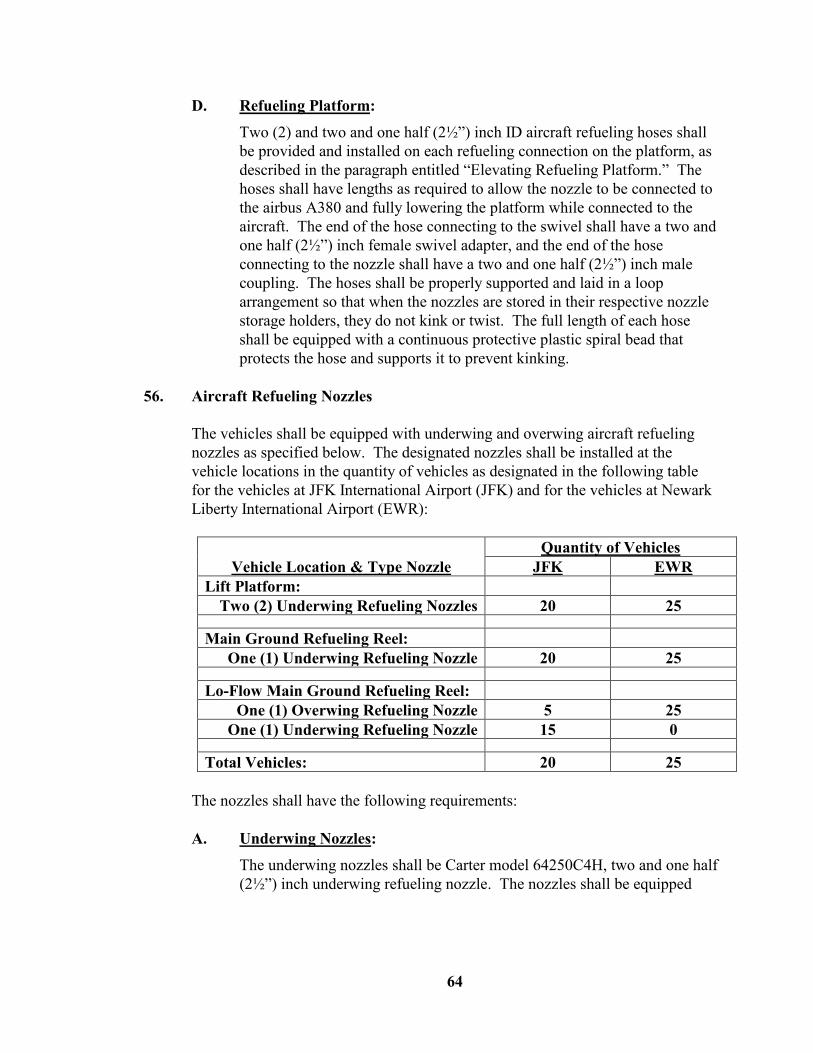
64
D. Refueling Platform:
Two (2) and two and one half (2½”) inch ID aircraft refueling hoses shall be provided and installed on each refueling connection on the platform, as described in the paragraph entitled “Elevating Refueling Platform.” The hoses shall have lengths as required to allow the nozzle to be connected to the airbus A380 and fully lowering the platform while connected to the aircraft. The end of the hose connecting to the swivel shall have a two and one half (2½”) inch female swivel adapter, and the end of the hose connecting to the nozzle shall have a two and one half (2½”) inch male coupling. The hoses shall be properly supported and laid in a loop arrangement so that when the nozzles are stored in their respective nozzle storage holders, they do not kink or twist. The full length of each hose shall be equipped with a continuous protective plastic spiral bead that protects the hose and supports it to prevent kinking.
56. Aircraft Refueling Nozzles
The vehicles shall be equipped with underwing and overwing aircraft refueling nozzles as specified below. The designated nozzles shall be installed at the vehicle locations in the quantity of vehicles as designated in the following table for the vehicles at JFK International Airport (JFK) and for the vehicles at Newark Liberty International Airport (EWR):
Vehicle Location & Type Nozzle Quantity of Vehicles
JFK EWR Lift Platform:
Two (2) Underwing Refueling Nozzles 20 25
Main Ground Refueling Reel: One (1) Underwing Refueling Nozzle 20 25
Lo-Flow Main Ground Refueling Reel: One (1) Overwing Refueling Nozzle 5 25
One (1) Underwing Refueling Nozzle 15 0
Total Vehicles: 20 25 The nozzles shall have the following requirements: A. Underwing Nozzles:
The underwing nozzles shall be Carter model 64250C4H, two and one half (2½”) inch underwing refueling nozzle. The nozzles shall be equipped
65
with a two and one half (2½”) inch hose swivel and a one hundred (100) mesh strainer that is easily removable for inspection and cleaning. The swivel retaining screws or any quick disconnect retaining latches shall be safety wired. The fueling nozzles shall be equipped with Gammon Technical Products Part #SPR-PR6R fueling nozzle protectors.
B. Overwing Nozzles:
The overwing nozzles shall be OPW model 295SA, one and one half (1½”) inch overwing refueling nozzle with a Jet-A nozzle tip, (no substitutes will be permitted). The nozzles shall be equipped with a one and one half (1½”) inch hose swivel and a one hundred (100) mesh strainer that is easily removable for inspection and cleaning. The fueling nozzles shall be equipped with a nozzle-to-aircraft grounding pin.
57. Underwing Nozzle Storage Holders
Each underwing nozzle shall be stored in a positive locking nozzle storage holder that operates with an interlock system to indicate when the nozzle is unstowed. Each nozzle storage holder shall be positioned in a readily accessible location. Each nozzle storage holder shall be of a rigid design and shall be capable of fully securing and locking the underwing nozzle with a dust cap in the stored position so that the nozzle surface remains fully covered when in the stored position. Bayonet type holders are not acceptable. The dust cap shall be installed with a nut and bolt type of assembly to the storage holder. The holders shall be made of heavy-duty high strength aluminum and/or stainless steel. The holders shall have quick acting and positive locking mechanisms to secure the nozzles. The locking mechanisms shall be of a design that is easily accessible and simple to operate. The holders shall accommodate the nozzle with a cap and have adjustments to maintain tightness of the nozzle when stored. The storage holder’s interlock system shall provide positive acting so that it allows misalignments when storing the nozzles, vibrations, and a minimal amount of nozzle movement that will not activate the interlock system when the vehicle is driven. The complete unit shall be easily adjusted and disassembled for maintenance. Each nozzle storage holder shall be positioned so that when the nozzle is stored, it is protected from any precipitating weather conditions and to facilitate nozzle insertion and removal by the operator. Each holder shall function and be used in such a manner that when the nozzle is inserted, the respective portion of the interlock system is deactivated. Each holder's interlock shall be connected to the vehicle’s interlock system, so that it operates as specified in the paragraph entitled “Interlock System.”

66
58. Overwing Nozzle Storage Holders Each overwing nozzle shall be stored in a positive locking nozzle storage holder that operates with an interlock system to indicate when the nozzle is unstowed. The nozzle storage holder shall be positioned so that the nozzle is stored vertically with the spout directed downward. Each nozzle storage holder shall be positioned in a readily accessible location. Each nozzle storage holder shall be positioned so that when the nozzle is stored, it is protected from any precipitating weather conditions and to facilitate nozzle insertion and removal by the operator. Each holder shall function and be used in such a manner that when the nozzle is inserted, the respective portion of the interlock system is deactivated. Each holder's interlock shall be connected to the vehicle’s interlock system, so that it operates as specified in the paragraph entitled “Interlock System.”
59. Deadman The refueling control system shall be equipped with a fixed storage bracket that allows the operator to wrap the fifty (50) feet of the deadman cable and also provide storage receptacle for the deadman control. The complete assembly shall meet all NFPA 407 and NEC requirements. The bracket shall be located on the LH side of the vehicle so that it can be easily operated. A storage receptacle for the deadman control shall be installed on the elevating platform to store the deadman control located on the elevating platform.
60. Static Grounding Reels The system shall be equipped with two (2) Gammon manual rewind static grounding reels, one installed on each side of the vehicle, in locations that are easily accessible by the operator. The reels shall be equipped with seventy-five (75’) feet of one eighth (1/8”) inch High Visibility aircraft static grounding cable and 100 amp grounding clamp. In addition to the grounding clamp, the reels shall also be equipped with a grounding plug. Each reel shall have handles to rewind the reels and a protective scuff guard to protect the grounding cable. The reels shall be electrically bonded together by means of a properly sized grounding conductor to the vehicle frame. Resistance shall not exceed twenty-five (25) Ohms between the two (2) grounding clamps of the reels.

67
61. Static Grounding Posts The vehicle shall be equipped with two (2) grounding posts located near the grounding reels, one installed on each side of the vehicle, in locations that are easily accessible by the operator.
62. Emergency Fuel Shut-Off Switches The vehicle shall be equipped with emergency fuel shutoff switches. Activation of any one of the switches will completely shut down the refueling system. Emergency fuel shutoff switches shall be two (2) position manually operated switches, properly rated for the application and meet all NFPA 407 and NEC requirements. Emergency fuel shutoff switches shall be installed at the following locations: Left side of the vehicle
Right side of the vehicle
Top of the elevating platform
The complete refueling system and all deadman controls shall be deactivated after any emergency fuel shutoff switch is activated. If the refueling system is operating, after any emergency fuel shut-off switch is activated, the refueling system shall immediately completely stop all refueling operations so that the quantity of fuel dispensed shall not exceed a quantity in gallons of five percent (5%) of steady flow, measured from the time that any emergency shutdown switch is activated. Each switch shall have the handles painted red, be labeled “Emergency Fuel Shutoff” and “Push,” and shall have additional indications as required to comply with NFPA 407.
63. Interlock System The vehicle shall be equipped with an interlock system. All components and operating functionality shall be provided so that the interlock system operates as specified herein and as required by ATA 103, NFPA 407, SAE ARP5818, and SAE ARP5918. The safety interlock system shall operate as follows. A. Operation of Interlock System: The safety interlock system shall
operate so that when it is activated, it shall operate as follows:
1. Apply the vehicle’s parking brakes at a regulated application rate when the interlock system is activated

68
2. Allow the vehicle’s parking brakes to be released by use of the cab-chassis parking brake control in the cab when the interlock system is deactivated
3. Indicate that the interlock system is activated by an amber interlock indicator light located on the dash that is operational only when the ignition switch is in the “On” position
4. Turn “On” the vehicle’s brake lights only when the ignition switch is in the “On” position and the refueling system is not activated
5. Allow the refueling system to be operational by allowing the deadman controls to be operational only if the following conditions are met:
The emergency shutoff switches are all in the deactivated position, and
The interlock system is activated, and
The vehicle’s parking brakes are applied, and
The PTO/Pump is activated, and
The product tank internal valve is open, and
The product tank vent is open
B. Activation of Interlock System: The safety interlock system shall be
automatically activated when any of the following conditions exist:
1. The vehicle’s air brake system is lower than 60 PSIG, or
2. The product PTO/pump system is activated, or
3. Any refueling nozzle is removed from its nozzle storage holder, or
4. The lift platform is lifted from the full down position, or
5. The vehicle’s wheel chocks are removed from their storage compartment, or
6. Top loading system is activated, or
7. The bottom loading system is activated, or
8. The product tank internal valve is open, or
9. The product tank vent is open
C. Deactivation of Interlock System: The safety interlock system shall be
automatically deactivated when any of the following conditions exist:

69
1. The product PTO/pump system is deactivated
2. The vehicle’s air brake system is higher than sixty (60) PSIG, and
3. All refueling nozzles are stored in their nozzle storage holders, and
4. The lift platform is in the full down position, and
5. The vehicle’s wheel chocks are stored in their storage compartment, and
6. The refueling system is deactivate (The deadman controls are not operational), and
7. Top loading system is deactivated, and
8. The bottom loading system is deactivated, and
9. The product tank internal valve is closed, and
10. The product tank vent is closed
D. Interlock Override System: For emergency situations, the safety
interlock system shall be equipped with an Emergency Interlock Override switch located on the front left side of the vehicle, above the bumper. The switch shall be safety wired in the normal position and be properly labeled “Interlock Override.” The interlock override switch shall operate so that when it is activated, it allows the vehicle’s parking brakes to be released by use of the cab-chassis parking brake control in the cab, and will also operate as follows:
1. Deactivate the complete refueling system so that it is not operational (Deadman controls are deactivated), and
2. Overrides all conditions listed in “B” above and the system releases the vehicle’s service brakes as applied by the interlock system
3. Override the requirement to have all refueling nozzles stored in their nozzle storage holders, and
4. Override the requirement to have the lift platform in the full down position, and
5. Override the requirement to have the vehicle’s wheel chocks stored in their storage compartment, and
6. Deactivate the bottom loading system, and
7. Close the product tank internal valve, and
8. Close the product tank vent, and
70
9. Activate the vehicle’s four (4) way flashers, when the ignition switch is in the “On” position
10. Allow the operator to drive the vehicle when the operator deactivates the PTO/Pump (places it in Road Mode) and releases the vehicle’s parking brakes (Provided that the vehicle’s parking brake air system is higher than 60 PSIG
The system shall be operated with PLC, proximity sensors, and all other required sensors and control devices as specified in the paragraph entitled “Electrical System.”
64. Electrical System A. Electrical Standards
All installed electrical equipment, lighting, and electrical components shall conform to:
All system electrical circuits shall meet all latest NEC, SAE ARP5818A, and all applicable code requirements.
SAE Standards J1292, “Automobile, Truck, Truck-Tractor, Trailer, And Motor Coach Wiring”
SAE Standards J1127, “Battery Cable”
SAE Standards J1128, “Low Tension Primary Cable”
All terminal connections shall conform to SAE Standard J163, “Low Tension Wiring And Cable, And Splice Clips”
All lamp circuits shall meet SAE Standard J575, “Test Methods And Equipment For Lighting Devices”
All fused circuits shall conform to SAE Standard J156, “Fusible Links”
All circuits shall conform to SAE Standard J541, “Voltage Drops For Starting Motors”
All lighting controls, switches and indicator lamps shall be mounted and properly labeled on a control panel.
Placement of all work lights, body lights, indicator lamps, controls, and panels shall be approved by the engineer prior to installation.
Work lights, body lights, indicator lamps, storage compartment lights and switches shall be of the shock and vibration resistant design.

71
The Contractor shall provide a full schematic of the body electrical system for all body lighting, indicator lamps, auxiliary equipment, accessory lighting and control circuits (including automatic reset circuit breaker size, wire size with color code, switch, and indicator lamp make, model and part numbers). This diagram and schematic shall be in addition to the chassis manufacturer’s furnished electrical manual.
All vehicle body lighting, reflective devices and conspicuity systems shall conform to FMVSS 108 requirements. All body lighting and wiring shall be of LED sealed lighting system design. All work lights, body lights, indicator lamps, lights and switches shall be shock and vibration resistant design.
B. General Electrical System Design
The electrical system shall be designed utilizing the following electrical components as needed for the design of the circuits, and any other specific functional electrical components as recommended by the Contractor, to provide an easily maintainable electrical system:
1. All electrical relays, fuses, circuit breakers, and electrical service components shall be centrally located and installed on an electrical panel or enclosure
2. All circuits shall have adequately sized copper stranded wire for the current and voltage drop requirements in accordance with the applicable SAE and NEC requirements to continuously operate each component or electrical system for the required application
3. Circuits that exceed twenty (20) Amps and are operated by a switch shall operate through a waterproof continuous duty Tyco Bosch Hi-Amp Power Relays with screw terminals with parallel and series diodes, unless the component is equipped with a manufacturer’s integral operating system
4. Dash mounted switches shall first utilized the cab-chassis manufacturer’s upfitter switches and if additional switches are needed the switches shall be Waytek, Inc. model 44237 Amber LED Fat Bat round rocker switches, and, when several area required, the switches shall be centrally located on the dash or installed onto a panel secured to the dash
5. Electrical system shall utilize a OptiFuse Part Number BLR-I-310 fuse block with LED indicators, 10 position fuse block utilizing APR type fuses, rated at 30A per circuit and 100A input, a fuse block cover, and each circuit properly labeled

72
6. Cooper Bussmann Transportation Products Series 18X Hi-Amp Circuit Breakers waterproof circuit breakers, manual reset switchable waterproof surface mount circuit breakers
7. All high amperage power supply cables for hose reels, battery switches, or other equipment where power is provided directly from the battery shall be of flexible stranded copper welding cable and be covered with high temperature wire loom with a minimum rating of minus forty degrees (-40°) Fahrenheit to three hundred degrees (300°) Fahrenheit.
8. All fuses, circuit breakers, relays, and connectors shall be sealed waterproof type
9. All connectors shall be covered with a protective shield, equipped with rubber boots, and battery positive terminal shall have a rubber protective cover guard
10. All cables and wiring installed by the Contractor shall be of a type, size and color or otherwise approved identification code in accordance with appropriate SAE and/or NEC standards and codes.
11. Wires shall be enclosed in protective high temperature wire loom of appropriate size and protected from chaffing or cutting by grommets or other bulkhead connections, and clamped or fixed for protection from vibration and movement wherever appropriate.
12. All equipment installed on the interior of the cab shall not interfere with the vehicle’s air bag deployment zones.
All switches shall be "ON" in the up position (if the switch is a toggle/rocker switch) and shall have an indicator lamp per switch and be accessible from the driver’s position. Each switch shall be properly labeled with and engraved plastic label or other permanent durable label approved by the Engineer. Selection, location and placement of all auxiliary equipment and lighting, i.e., work lights, body lights, indicator lamps, switches, controls, relays and panels shall be approved by the engineer prior to installation.
C. Refueling System Electrical Design
The vehicle shall be equipped with a Programmable Logic Controller (PLC), forty-eight (48) channel minimum, and programmed with the functionality to operate vehicle and refueling system functions as required by these specifications. The Contractor shall develop and provide a logic

73
chart that details the functionality of the PLC and the operation of each system’s circuit for every possible condition (mode) of operation. The interlock system shall be completely operated with Turck, Inc. Proximity Sensors and other electrical operating components necessary for the system. The proximity sensors shall be equipped with led indicators and have all sealed connections. The PLC shall be rated NEMA 6 (IP67) rated. All electrical and electronic components requiring protection shall be installed in a NEMA 4X rated enclosure(s) and shall have: NEMA 4X (IP66) rated couplings of the enclosure with NEMA 4X
(IP66) rated electrical cabling/wiring that is run into the enclosure
Safety barriers and insulators sufficient to protect all electrical and electronic systems
Terminal strips and fuses as required
Grounding post
Label all components, each wire, and each terminal connection
All the electrical and electronic system wiring shall run full length from component to component without splicing, and shall have adequate mechanical strength for the application. All wiring shall be properly sized with proper conductor(s) to adequately carry the maximum applied current for each circuit in accordance with NEC requirements. All lighting equipment shall be the shock-mount type. Rubber grommets shall be installed where wires go through walls or bulkheads. All adequate cables or wiring that shall be hypalon or superior insulated wire, run in suitable synflex tubing and shall terminate with weather-tight connections. All wiring connections shall be made in a weatherproof sealed electrical box. Where multiple connections are made, they shall be made on terminal junction blocks. All circuits for all components and lighting circuits shall be fused on a fuse block panel or have resettable circuit breakers. In-line fuses shall be used only if accepted by the Engineer. Each hose reel motor shall be protected with a manual reset circuit breaker and a fuse shall be installed for each hose reel switch. The vehicle shall have a main electrical box for all system components and connections, and a lighting electrical box for all lighting system components and connections. The boxes shall be weatherproof sealed electrical boxes with hinged cover, installed in locations that are readily accessible for maintenance, inspection and trouble-shooting. All electrical components including relays, fuses, fuse block panels, junction blocks, circuit breakers, etc. shall be installed in the electrical box and properly spaced for ease of maintenance. All wiring to components shall originate from the electrical

74
boxes. All wires, breakers, terminals, fuses, etc., shall be properly coded or labeled to identify each circuit and to match all drawings. Supply and install the required batteries, as specified in the cab-chassis section, in a suitable enclosure with a removable or hinged cover. The batteries shall be strapped down with sufficient clearance between the battery and the top cover. The batteries shall be installed outside the cab in a location readily accessible for checking and replacement. The batteries shall be wired to the battery disconnect switch, properly rated and installed. The switch shall be installed as close as possible to the batteries. All connections on the switch shall be properly protected with protective rubber boots. The switch shall be located on the left side of the vehicle, behind the cab and marked “Battery Disconnect Switch” in one half (½”) inch red letters. All switches and warning lights shall be properly mounted and labeled on a single panel in the cab or on the control panel. All switches shall have one “On” indicator light per switch. The complete electrical, electronic, and lighting systems shall be in accordance with NFPA 385, NFPA 407, NEC requirements, and “Port Authority Airport Rules and Regulations.”
65. Air System
All components for a complete, properly functioning air system shall be provided. All air components shall be properly sized and installed. All air lines and components shall be heavy duty and be properly routed and supported. Each air line shall be labeled on each end and easily identified on the drawings. The air system shall be properly designed and installed so that the complete system properly operates at any ambient temperature from minus twenty degrees (-20) Fahrenheit to one hundred and twenty degrees (+120) Fahrenheit for any duration of time. The air system shall consist of the following components and all other components as required but not specified: A. The auxiliary air system shall have a minimum of one (1) reservoir and it
shall have a volume required to satisfactorily operate the refueling system.
B. The auxiliary air system shall be equipped with a relief valve set at one hundred and fifty (150) PSIG.

75
C. A Velcon Aquacon model VF-31E air dryer with a differential gauge. The Aquacon shall be a positive shutdown filter installed in the main air supply line.
D. All auxiliary air tanks shall be equipped with cable operated air tank drain(s). All tank drain valve cables shall be routed to one (1) location and grouped together side-by-side, in a readily accessible location. Each cable shall be installed through an assembly of pipe couplings and the cable looped so that each can be easily pulled to activate the valve. Directly above the drain cables shall be labeled “Auxiliary Air Tank Drains.”
E. All gauges as required shall be supplied and they shall be, dial type with two and one half (2-1/2”) inch face, silicone or glycerin filled, and zero (0) to one hundred and sixty (160) PSIG range.
F. Quick exhaust valves shall be installed at all locations as required. All quick exhaust valves shall have exhaust port openings facing down or elbowed to a down position.
G. All air valves shall be of the same make and be readily available. All air valves shall have the minimum specifications required to operate with maximum reliably at the at any ambient temperature from minus twenty degrees (-20) Fahrenheit to one hundred and twenty degrees (+120) Fahrenheit for any duration of time.
H. All other components as required for the proper function of all systems, including pumping, hydraulic, pneumatic, electrical, etc.
66. Lights & Reflectors
The vehicle shall be equipped with all lights to comply with all federal, state, and airport rules and regulations. All sets of lights shall be separately fused and controlled by switches. All body lighting shall be Betts vapor-proof snap seal system and be of the led type lights. All lights and reflectors shall be of a bolted assembly. The following vehicle lighting shall be supplied: A. Cab
The cab shall be equipped with all cab-chassis manufacturer’s standard lighting but shall include not less than headlights, signal lights, marker lights, clearance lights, reflectors, etc., as required to comply with all FMVSS 108 requirements.

76
B. On The Front Of The Tank
Two (2) amber clearance lights, installed at the highest structure, one on each side at the top corner of the tank, visible from all directions.
An amber three (3) light cluster identification lights, installed at the highest structure at the top center of the tank.
C. On Each Side Of The Vehicle
One (1) amber clearance light, installed at the top front of the tank, below the tank section.
One (1) amber clearance light, installed at the center of the tank, below the tank section.
One (1) amber arrow turn signal light, installed at the center of the tank, below the tank section, to operate with the turn signals.
Red and amber, Class A reflectors.
D. On The Rear Of The Vehicle
Two (2) assemblies of red stop, tail, backup, and turn lights with side marker lights, one on each side of the vehicle. Each assembly shall be installed so that it is flush with the rear of the bumper.
One (1) red brake light assembly (a 3rd stop light). The light shall be installed at the center of the vehicle and at a location and height to be determined during the production of the first vehicle.
Two (2) red clearance lights, installed at the high structure at the top corner of the tank, one on each side visible from all directions.
A red, three (3) light cluster identification lights, installed at the top rear center of the tank.
One (1) white license plate lamp and bracket, installed in a visible location.
Two (2) flood lights installed at the top of the tank, one (1) on each side of the vehicle, activated when the vehicle is placed in reverse to illuminate the rear area of the vehicle.

77
E. On The Top Of The Vehicle At The Highest Point
A low profile amber LED flashing beacon with a switch in the cab on the dash. The beacon shall not be a strobe light.
F. Other
Conspicuity materials (i.e., retroreflective sheeting (or reflex reflectors) as required on trailers or truck tractors. Exact locations to be determined by the Engineer.
Notwithstanding the other requirements of this numbered section, ensure that the lights and reflectors are located on the vehicle so that they clearly mark its dimensional extremities from all directions and as required by the “Port Authority Airport Rules And Regulations.”
67. Control Panel A control panel shall be provided on the left side of the vehicle, conveniently located for ready observation by the operator. The control panel shall be designed and manufactured so to reflect a rigid construction with aesthetic appearance. The panel shall be of stainless steel or aluminum construction, of proper size, and have approximately four (4”) inch sides to protect all instrumentation. All instruments shall be illuminated and labeled with engraved plastic labels. The control panel shall have the following minimum displays, gauges, and indicators: Digital system display showing the refueling pressure and all other
indicators as specified in the paragraph entitled “Digital Control System Equipment Requirements”
Meter Electronic Register
Product Tank Digital Display
Filter-separator differential pressure gauge with a differential pressure gauge test switch located in accessible location
Filter monitor differential pressure gauge with a differential pressure gauge test switch located in accessible location
Filter monitor high differential shutdown indicator
Two and one half (2-1/2”) inch, dial type, pump output pressure gauge
Two and one half (2-1/2”) inch, dial type, auxiliary air tank pressure gauge
78
Digital or a four (4”) inch dial type thermometer: The thermometer shall have the probe installed approximately 6 inches downstream of the meter and the probe installed in a thermo well that extends to the center of the product pipe
Amber water detection warning light, normally “On” when refueling system is activated, and “Off” when detection system is activated
Red refueling system ready to operate light, normally “On” when refueling system is ready to operate
Fueling/Defueling indicator to show when the defueling system is activated as specified below
All other refueling system displays and indicators required for the operation of the system
All dial type gauges shall be either glycerin or silicone liquid filled type gauges. All instruments on the control panel shall be protected from damage by external objects. The front of the control panel shall be covered with a one half (½”) inch thick Lexan cover. The cover shall be secured to the control panel with stainless steel bolts and nuts. The control panel shall have an easily accessible service panel beneath the control panel with the following minimum items: An air chuck with a protective strapped rubber plug to fill the air system
through the vehicle’s wet reservoir
The fuel/defuel control
All other controls required to operate the refueling system
The control panel shall also have an easily accessible locking maintenance service panel beneath the control panel for controls required for the maintenance of any component or systems that require periodic checking, testing, or service. The maintenance service panel shall have the following minimum controls: Primary/Secondary Pressure Control that allows to test the refueling
system’s Primary or Secondary Pressure Control System
Reset Switch to reset the Filter-Separator’s high differential shutdown system
Reset Switch to reset the Filter Monitor’s high differential shutdown system

79
All other refueling system controls required for testing and checking the operation of the refueling system
All other controls needed to test or adjust the refueling system shall be located in this secured area
68. Fire Extinguishers
The vehicle shall be equipped with two (2) twenty (20) pound Ansul model IK20G Purple K (PKP) dry powder fire extinguishers, one (1) installed on each side of the vehicle. Each fire extinguisher shall be installed in an Ansul quick release bracket, assembly 14091. The fire extinguishers shall be installed in a horizontal position and be easily accessible from the ground.
69. Wheel Chocks And Storage The vehicle shall be equipped with one (1) set of wheel chocks and a wheel chock storage, installed on the left side of the vehicle in an accessible location. The wheel chock storage shall be designed to securely hold the chocks and shall be easily accessible to store and retrieve chocks for immediate use. The wheel chocks shall be secured to the chock storage with a cable with sufficient length so that they can be properly set to block the rear wheels or stored. The chock storage shall be equipped with an interlock proximity switch that operates with the interlock system so that when the wheel chocks are removed from storage the interlock system is activated.
70. Vehicle Body Accessories The vehicle shall be equipped with the following items and accessories, installed in a quality manner and to reflect aesthetic appearance: A. Rear Bumper
A heavy duty rear bumper, installed and reinforced directly to the trailer or chassis frame rails. The bumper shall be the full width of the body and manufactured from structural steel ship channel that is twelve (12”) inches high with four (4”) inch wide flanges. The bumper shall have a step at the required height to allow the operator access to the rear ladder as specified herein. The bumper shall be designed so that it includes flush mounted rear lights and rubber dock bumpers. The bumper and all components provided on the bumper shall be of a bolt-on installation only. Also a reflective fluorescent orange flexible guide post shall be installed at each

80
end of the rear bumper that facilitates the driver to view each end of the bumper.
B. Fenders
All wheels shall be provided with stainless steel or aluminum fenders to retain any road splash. All fenders shall be properly supported, be of a bolt-on installation, and be easily replaced.
C. Backup Alarm
A vapor-proof back-up alarm located at the rear, inside one (1) of the trailer or chassis frame rails. The backup alarm shall meet all OSHA and SAE J994 requirements.
D. Rear Tow Hooks
The vehicle shall be equipped with two (2) rear tow hooks. The tow hooks shall be heavy duty cast type and properly bolted (not welded) to the trailer or chassis frame. The hooks shall be accessible from the rear of the vehicle.
E. Shaft Guards
All rotating shafts, including the drive shaft and the PTO/Pump shaft, shall be equipped with guards to trap the shaft in the event a shaft or universal joint breaks loose. The guards shall be positioned along the length of each shaft and provide proper clearance and shall provide a clearance of approximately two (2”) inches around the shaft.
F. Other
All other work necessary or required to adapt this unit for the intended operation shall be performed. This includes all modifications to the engine, chassis, cab, electrical system, air system, brake system, etc.
71. Vehicle Tests And Certificates Documentation
All tests and all certifications shall be documented in a binder designated as the vehicle tests and certificates booklet. Each vehicle shall have a test and certificates booklet and it shall be identified with a general description of the vehicle, the VIN number, the Vehicle Number, and vehicle manufacturer’s name and identification number. All tests shall be fully documented on separate test sheets and in separate sections. In addition, the booklet shall have a section for vehicle qualification.
81
Each vehicle booklet shall have documentation of all tests as performed by the Contractor and as required in the paragraphs entitled “Testing Complete Vehicle Operation,” “Testing Tanks And Product Piping,” “Refueling System Testing,” and all other tests as specified within these specifications and as required in standard industry practice. After completion of all tests and before delivery of each vehicle, the Contractor shall submit two (2) test booklets, an original and a copy. In addition, the Contractor shall also scan the contents of each Booklet into a PDF file for each vehicle and all booklets saved on a CD. The CD shall be forwarded to the Engineer. The original shall be sent to the Engineer and a copy shall be sent to the delivery location, as listed in Appendix D entitled “Delivery Locations For Vehicles, Manuals, & Training.” The Contractor shall retain a copy of the booklet for future reference. The Contractor shall verify and assure that each booklet contains all final satisfactory performance and operational tests, and other certifications required to place the vehicle in-service.
72. Testing Complete Vehicle Operation The Contractor shall fully test the operation and performance of each laden and unladen vehicle to assure that all function, systems and components operate perfectly and to the Port Authority’s satisfaction. All components needing adjustment shall be properly set and safety wired or locked, to prevent tampering. The vehicles shall be completely tested for all different types of operations and maneuvers required at the airports. Document all tests in the vehicle tests and certificates booklet described in the paragraph entitled “Vehicle Tests And Certificates Documentation.” The tests performed on each vehicle shall include the following: A. Service Brakes And Parking Brakes
Test the vehicle’s service brakes and parking brakes with the fully laden vehicle to meet 49CFR DOT requirements.
B. Vehicle Air System Leakage And Air Recovery Time
Test the vehicle’s air system leakage and air recovery time to meet 49CFR DOT requirements.
C. Vehicle Lighting And Electrical System
Test the vehicle’s complete lighting system and electrical system including lights, switches, gauges, electric reels, backup alarm, etc.

82
D. Vehicle Maneuverability
Test the drivability and maneuverability of the vehicle and include wall-to-wall turning diameter turning left and right, steering, engine operation, transmission shift, PTO, top speed, etc.
E. Other
Perform all other tests as required to check the integrity, operation, and performance of the vehicle.
73. Testing Tanks And Product Piping All vehicle product tank shall be hydrostatically tested at a minimum pressure of five (5) PSIG. Tank shall be fully tested in accordance with pressure and leakage tests required by 49CFR178.346-13. Each tank shall have the marking in accordance with 49CFR178.346-14 and tank certification in accordance with 49CFR178.346-15. All other product tanks shall be hydrostatically tested at a minimum pressure of twice the working pressure. The complete product piping assembly, from the main service valve to all discharge nozzles, shall be hydrostatically tested at a minimum pressure of one hundred and fifty (150) PSIG for twenty (20) minutes. The piping test shall be performed with the same procedures as used in testing the tanks. In addition, all sump drain lines shall be hydrostatically tested at a minimum pressure of sixty (60) psig for twenty (20) minutes.
74. Refueling System Testing The Contractor shall have on its premises the required test facility with the stand to perform all refueling system tests as required in these specifications. All tests shall be performed in accordance with these specifications and the latest edition of SAE ARP5918, ATA Specification 103 requirements, and NFPA 407 requirements. The Contractor shall perform all required pressure tests on all systems on the vehicle, including hydraulic, system handling the product, drains, etc. to locate any faulty connections or leaks. The Contractor shall also perform all required performance tests. All components needing adjustment shall be properly set and safety wired or locked, to prevent tampering. After all adjustments are completed, test the unit for performance by simulating aircraft refueling operation, with all practical combinations of hookups. Completely test the vehicle for all different types of operations, including refueling, in all possible pressure and surge conditions. The complete system shall be tested only with clean jet fuel that meets ASTM D1655 specifications. Upon request, the

83
Contractor shall provide a laboratory test analysis of the fuel used to test the vehicles certifying that the jet fuel meets the ASTM D1655 specifications. All tests shall be documented in the vehicle tests and certificates booklet described in the paragraph entitled “Vehicle Tests And Certificates Documentation.” The tests performed on each vehicle shall minimally include the following: A. Air System Test: The entire system shall be tested at one hundred and
fifty (150) PSIG for a minimum of one (1) hour. Leakage shall not exceed a loss five (5) PSIG. Also the auxiliary air system shall only charge when the vehicle’s air system exceeds sixty-five (65) PSIG.
B. Refueling System Pressure Test: Each piping sub-assemblies for the entire refueling system shall be hydrostatically tested to two hundred (200) PSIG, for a minimum of twenty (20) minutes, without leakage. After the vehicle is complete, the entire piping system from the hydrant coupler to all nozzles shall be hydrostatically tested as described in the paragraph entitled “Testing Tanks And Product Piping.”
C. Functional Flow Tests: The system shall be fully tested by refueling from 0 GPM Flow Rate to Maximum set Flow Rate, and simulating a minimum of 4 different back pressure scenarios on the refueling manifold, using any combination of either single or dual platform, or any single ground fueling nozzle. The underwing refueling system shall operate only when it is activated by any deadman valve and the overwing refueling system shall only operate when it is activated by the pre-set meter and overwing nozzle manual activation. For all refueling operations scenarios, the refueling system shall shutdown within a quantity in gallons of five percent (5%) of steady flow rate when any emergency shutdown valve is activated, deadman is released, water sump control valve is activated, interlock override is activated, etc., operating either with the primary or secondary pressure control system, and as described herein. All pertinent pressure, flow, shudown, and other essential readings shall be recorded from the pump to the nozzle, as well as the back pressure on the refueling manifold.
Once the complete system is set, the final refueling system test shall include simulating aircraft refueling, by dispensing fuel with the two underwing nozzles on the platform, against a forty (40) PSIG back pressure, and dispensing a minimum of five thousand (5,000) gallons two (2) consecutive times without any malfunctions or disruptions.

84
D. Flow Rate Limits
Flow rate shall be limited to seven hundred and fifty (750) GPM when dispensing fuel from the two lift platform hoses
Flow rate shall be limited to four hundred and fifty (450) GPM when dispensing fuel from either one of the two lift platform hoses
Flow rate shall be limited to four hundred and fifty (450) GPM when dispensing fuel from the Main Ground Refueling Hose
Flow rate shall be limited to one hundred and fifty (150) GPM when dispensing fuel from the Low Flow Ground Refueling Hose when equipped with the underwing nozzle
Flow rate shall be limited to forty (40) GPM when dispensing fuel from the Low Flow Ground Refueling Hose when equipped with the overwing nozzle, and the overwing nozzle shall be deactivated and not dispense any fuel unless the meter pre-set is utilized to permit a prescribed amount of fuel to be dispensed
The system shall limit the flow rate to the lowest fail-safe in any possible operating conditions
E. Pressure Limits:
Fuel pressure shall be limited to forty (40) PSIG or less (+ 0 - 4 PSIG) measured at a point directly downstream of any nozzle dispensing fuel (aircraft manifold) when the system is controlled by the primary pressure control system
Fuel pressure shall be limited to fifty (50) PSIG or less (+ 0 - 4 PSIG) measured at a point directly downstream of any nozzle dispensing fuel (aircraft manifold) when the system is controlled by the secondary pressure control system
The secondary pressure control system shall maintain complete control when the primary system becomes inoperative or exceeds the primary control limits
The primary and secondary control systems shall maintain pressure accuracy at the refueling manifold throughout the flow range (zero (0) to seven hundred and fifty (750) GPM).
F. Refueling System Pressure Stability
The refueling system shall operate in a stable and controlled manner and without any significant hunting within fifteen (15)

85
seconds of continuous refueling and the refueling pressure shall not fluctuate greater than 5 PSIG during startup or during any normal back pressure fluctuations that occur during a refueling operation.
The fueling pressure shall be stable and shall not exceed the allowable control pressure at flow rates from one hundred and fifty (150) GPM up to seven hundred and fifty (750) GPM
G. Refueling System Pressure Recovery
The refueling system shall operate in a stable and controlled manner and without any significant hunting when recovering at startup or during any refueling operation. Specifically, the system shall operate so that when the system is pressurized to the full pressure, forty (40) PSIG with the Primary System or fifty (50) PSIG with the Secondary System, with the manifold closed, once the manifold is opened to flow a minimum flow rate of one hundred and sixty (160) GPM, the system shall quickly recover without dropping the pressure measured directly downstream of the nozzle below twenty-five (25) PSIG.
H. Surge Pressure Limits:
Maximum momentary surge pressure shall be limited to one hundred and twenty (120) PSIG measured at a point directly downstream of any nozzle dispensing fuel (aircraft manifold) during a complete aircraft refueling valve(s) closure (completely stopping fuel flow) made in a timeframe not to exceed two (2) second from full open to fully closed when refueling at any flow rate up to the maximum rate of seven hundred and fifty (750) GPM and with any manifold back pressure (aircraft manifold).
Maximum momentary surge pressure shall be limited to one hundred (100) PSIG measured at a point directly downstream of any nozzle dispensing fuel (aircraft manifold) during a complete aircraft refueling valve(s) closure (completely stopping fuel flow) made in a timeframe not to exceed five (5) seconds from full open to fully closed when refueling at any flow rate up to the maximum rate of seven hundred and fifty (750) GPM and with any manifold back pressure (aircraft manifold).
Maximum locked-in static pressure immediately after a surge shall be limited to seventy (70) PSIG measured at a point directly downstream of any nozzle dispensing fuel (aircraft manifold).

86
I. Interlock Test: The complete interlock system and interlock override system shall be fully tested in accordance with the operation as specified in the paragraph entitled “Interlock System,” including testing of system response to each possible single point failure mode.
The primary and secondary refueling pressure control systems shall be fully tested and their performance and accuracy when dispensing from any possible combination of nozzles shall be fully documented on test sheets in the Vehicle Tests And Certificates Booklet described in the paragraph entitled “Vehicle Tests And Certificates Documentation.” The Contractor shall develop and implement a functional test program, subject to approval by the Engineer, to check the operation, integrity, and performance of the refueling system and all other systems and components on each vehicle. The Contractor shall perform all final tests at the Contractor’s plant. Any defects or failure of any component or system shall be immediately remedied by the Contractor. The Contractor shall be responsible for all expenses to have the product flow meter calibrated at Newark Liberty International Airport or JFK International Airport by a meter calibrating company licensed by the States of New York and New Jersey and approved by the Engineer. All tests requiring the use of liquids in the tank or piping system, shall be performed only with clean dry jet fuel. The final tests of each vehicle shall be performed at the Contractor’s plant with all filter elements, strainers, etc. installed. All tests on the first vehicle shall be performed with a new set of filter elements that are deemed test elements, and these test elements may be removed in accordance with adequate procedures for removing and storing to reuse the elements to assure that they do not become contaminated, and reuse the test elements to test subsequent vehicles. After testing each vehicle, the test elements shall be carefully drained, placed in plastic bags and cartons, and sealed to prevent contamination until they are needed for testing each of the subsequent vehicles. The Contractor shall supply a set of all new elements with each vehicle as required by the paragraph entitled “Filter-Separator/Monitor” The Contractor shall perform all final tests prior to the time the Engineer performs a final inspection of each vehicle. The Contractor shall notify the Engineer a minimum of thirty (30) days before performing a final test on any vehicle at the Contractor’s plant. The first vehicle shall be completely tested at the Contractor's plant, in the presence of the Engineer. At the Engineers option, the Contractor shall arrange for the Engineer to witness the tests of any or all subsequent vehicles at the Contractor’s plant prior to delivery. The Contractor shall be responsible to deliver each vehicle complete and fully tested to Newark Liberty International

87
Airport or JFK International Airport. The Contractor shall document all test results for each vehicle in the vehicle tests and certificates booklet and submit it to the Engineer prior to delivery of each vehicle. The vehicle shall be considered complete and accepted following approval by the Engineer at Newark Liberty International Airport or JFK International Airport after the Engineer has fully inspected, tested, and found the vehicle to be complete and fit for service. After the delivery of the first vehicle, the Contractor shall make arrangements that are mutually agreed to with the Engineer to provide a company qualified technician to prepare the vehicle for service herein referred to as a Make-Ready Process. The Make-Ready Process shall be the complete process to prepare the vehicle for service and shall include the filling and flushing of the vehicle with jet fuel, draining the vehicle, installing all filter elements, purging and relieving all wetted lines of air, setting up all programmable operating parameter, making all final adjustments, performing a complete final refueling flow test of the refueling system as required by these specifications, required by all applicable standards, required by the Contractor or Engineer, and a final test program approved by the Engineer. After the delivery of the first vehicle, the Contractor shall also rectify any outstanding items or corrections, make all adjustments, and review all processes and procedure to perform the complete Make-Ready Process with the Engineer and all other designated staff. Upon acceptance of the first vehicle, the Make-Ready Process shall be performed by others that are trained to perform the process by the Contractor at Newark Liberty International Airport or JFK International Airport. If there are any issues found, the Contractor shall be readily available to provide adequate procedures to rectify the issues. If the Contractor is unable to rectify an issue at the Engineer’s request, the Contractor shall be responsible to provide a company qualified technician on site at Newark Liberty International Airport or JFK International Airport to rectify the issue within a two day period or as mutually agreed to between the Contractor and the Engineer. After delivery of the first vehicle, each subsequent vehicle will undergo a make-ready process by others and they will perform all items identified by the Contractor as a Make-Ready Process, and in addition will also install additional decals around the vehicle and perform any other inspections and tests to assure proper operation and performance of the vehicle and the refueling system. All issues found will be immediately reported to the Contractor and the Contractor shall be responsible to rectify the issues as done with the delivery of the first vehicle.
88
75. Finishing And Painting The complete vehicle shall be finished with a quality commercial grade finish. All surfaces shall be free of dents, gouges, buckles, surface scaling, rust, corrosion, and other surface irregularities. All surfaces shall be cleaned and conditioned in accordance with the paint manufacturer's specification. All components shall be painted with the finished color(s) including wheels (inner and outer, bumpers, compartment interiors, ancillary equipment etc. The only exception shall be britework (chrome plated parts) grill, fusible links, grease fittings, filter membrane fittings, valve shafts, cylinder rams, vacuum breakers, components the operation of which would be impeded by painting and other components specifically designated by the engineer. Air lines, electrical tubing, cables, retaining clips, servos, solenoids, etc., and any other items as agreed to by the Engineer. As soon as practical after completion, prime each vehicle with two (2) coats of the primer specified below. Parts which mate or join and are inaccessible after assembly and require to be primed shall receive an additional coat of primer before assembly. Specified primers:
Gray Primer Approved By Finish Paint Manufacturer Or
Zinc Chromate Primer Note: The zinc chromate primer must be used on all aluminum components The final finish shall consist of three (3) coats of the paint specified below. The finish shall be of high gloss and uniform color with full hiding and shall be free from sags, runs, orange peel, crazing, pitting and other paint defects. The vehicle shall be painted with a urethane or polyurethane finish paint with the colors specified below. White: Dupont Imron #7372U:
The complete cab including the front fenders The tank upper sides starting from a horizontal straight line located
approximately six (6”) inches above the tank radius, tank top, complete tank front and rear heads

89
Walkway on the top of the tank including roll-over protective rail and the grating
Gray: Dupont Imron #72092U
The complete elevating platform including platform handrails The complete refueling system including all system framework, reels, rear
fenders, battery box, equipment rack, control panel, filter vessels, reels, brackets, etc.
The tank lower sides starting from the white horizontal straight line described above, and include the product tank bottom, product tank outriggers, product tank frame, and all product tank members
Black: Dupont Imron #99U
Chassis frame rails Front and rear bumpers Wheels Bright Yellow: Dupont Imron
All Access Steps, Grab Handles, And Handrails To Access Platforms Rear product tank access ladder Red
Valve handles Operating controls All Emergency Shut-Off Operating Controls Blue Reflective Stripes
The rear head of the product tank shall be provided with alternate four (4) inch wide blue reflective stripes on the white painted background in the shape of an inverted "V" having a sixty (60) degree included angle
The Contractor shall notify the Engineer when each vehicle is ready for finishing and arrange upon request for him to inspect the vehicle prior to painting. Address inquiries regarding paint to the Engineer. Upon request by the Engineer, supply a 4” x 6” paint sample for approval prior to painting. The Contractor shall ensure that all paint is either urethane or polyurethane paint. The Contractor shall be responsible to re-prime and re-paint any and all areas found to be painted with paint that is not polyurethane paint, all at no cost to the Port Authority.

90
Note: The entire vehicle and refueling system (including components, structural framework, platform, etc.) shall be painted in polyurethane paint.
76. Vehicle Decals And Labeling The Port Authority shall provide the Contractor with a Decal Kit for each vehicle and the Contractor shall be responsible to install all decals provided in the Decal Kit, and the Contractor shall also provide and install all other required striping, conspicuity markings, lettering, and labeling, including the DOT approved Flammable Liquid vehicle placards, and all other markings as required by the Port Authority Airport Rules And Regulations, ATA Specification 103, NFPA 407 and 49CFR, or as specified elsewhere in these specifications or requested by the Engineer. As the vehicles are operated by Allied Aviation, the Port Authority will make all arrangements to have Allied Aviation ship to the Contractor an Allied Aviation Tanker Vehicle Decal Kit packaged separately for each of the vehicles, and have Allied also provide the Contractor with specific instruction on the placement of all Allied Aviation decals. Each vehicle decal kit shall have the following decals for the Contractor to install on each vehicle: A. Cab - Exterior
Decal QTY
1. Allied Aviation 2
2. Vehicle Number 1
3. No Smoking 2
4. Owned By the Port Authority of NY & NJ 2
5. Did You Do Your Walk-Around 2
6. Warning- Have you Disconnected 2
7. Jet-A 2
8. Interlock Override with Normal & Activated
1
9. Flammable 1
10. Keep Exit Clear 1
11. Fire Suppression System "Normal & Activated 1

91
B. Cab Interior
Decal QTY
1. Vehicle Number 1
2. 20 MPH 2
3. Stop Test Brakes 1
4. Warning- Have you Disconnected 1
5. Did You Do Your Walk-Around 1
6. No Smoking 2
7. You’re Responsibilities 1
8. Fire Suppression System "Normal & Activated 1
C. Product Tank Exterior & Equipment
Decal QTY
1. Vehicle Number 3
2. Emergency Fuel Shut Off 2
3. Battery 1
4. Shut off Battery switch before Jump Starting 1
5. Caution Do Not Fuel Over 50 PSI 1
6. Allied Aviation (Large for side for tank) 2
7. Product Filter DP Chart 1
8. Shut off Battery switch before Jump Starting 1
9. Stay Back 50 FT 1
10. Flammable 3
11. Jet Fuel DOT 1863 4
12. Jet-A 3
13. Jet-A Health Advisory 1
D. Elevating Platform
Decal QTY
2. Flammable 1

92
3. Emergency Fuel Shut Off 1
4. Caution Do Not Fuel Over 50 PSI 1
The Contractor shall provide a front, left side, rear, right side and top view line drawing to provide paint and decal layout. The final layout of all decals shall be reviewed with the Contractor upon completion of the first vehicle, and all remaining vehicles shall be completed with the same decal layout. All decals, shall be properly installed on properly prepared surfaces as required by the decal manufacturer. The Contractor shall also provide and install all lettering, labeling, stripes, and symbols as specified below. The Contractor shall also be responsible that the vehicle is provided with decals and signage installed in all appropriate locations as required by regulatory requirements, and that there are all required decals that identify all controls, operating mechanisms, maintenance items, etc. In addition, the Contractor shall provide the following minimum components, controls, and indicators with engraved plastic plate labels with one half (½”) inch high letters to identify drains, sample valves, displays, gauges, indicator lights, and operating controls, etc. The vehicles shall be identified with a vehicle number as follows: Newark Liberty International Airport Vehicles: The first vehicle for Newark Liberty International Airport shall be assigned vehicle number 301, the second 302, and remaining vehicles as completed for Newark Liberty International Airport shall be assigned sequential numbers. JFK International Airport Vehicles: The first vehicle for JFK International Airport shall be assigned vehicle number 351, the second 352, and remaining vehicles as completed for JFK International Airport shall be assigned sequential numbers.

93
APPENDIX A AUTOMOTIVE PROCUREMENT
STANDARD CONTRACT TERMS AND CONDITIONS
PART I- GENERAL PROVISIONS
1. Intent These Contract Terms And Conditions apply to the purchase of the forty-five (45) 10,000 Gallon Aircraft Refueling Tanker Vehicles purchased with these specifications.
2. Definitions Authority or Port Authority: For the purposes of this agreement, the terms “Authority” or “Port Authority” mean The Port Authority of New York and New Jersey and/or the Port Authority Trans-Hudson Corporation (PATH), as applicable. Agreement/Contract: For the purposes of this agreement, the terms “Agreement” and “Contract” can be used interchangeably to mean the agreement entered into by the signatories of this document, and shall consist of the Specifications, this Appendix A, and any other appendices, attachments, exhibits or addenda, as outlined in the section entitled “Entire Agreement”. Contractor/Contractor: For the purposes of this agreement, the terms “Contractor” and “Contractor” can be used interchangeably to mean the entity entering into this Contract with the Port Authority of New York and New Jersey. Chief Procurement Officer: For the purposes of this agreement, Chief Procurement Officer means the Chief Procurement Officer of the Port Authority, or successor in duties, or her authorized representative. Engineer: As used in this agreement, the term "Engineer" means the Manager of the Central Automotive Division of the Port Authority, or his duly authorized representatives acting within the scope of the particular authority vested in them.

94
3. Contractor Requirement The Contractor must have or be closely associated with an adequate, as determined by the Engineer, service facility staffed by trained and experienced service personnel and a stock of repair parts suitable for a timely response to the Authority's vehicle service requirements. All warranty work that requires welding or any work that cannot be easily performed on-site at the Airport as deemed by the Engineer must be performed at the Contractor’s designated repair site. All costs of moving the vehicle to and from this repair site are to be at the Contractor’s expense, and included in the warranty. Warranty work that requires less than one half day’s work may be performed at the local automotive shop with permission from the shop supervisor, and prior notification and mutually agreeable scheduling. In such instances, Contractor staff must work cooperatively with Port Authority shop personnel in accordance with agency labor agreements.
4. Engineer’s Authority In the performance of the Work hereunder, the Contractor shall conform to all orders, directions and requirements of the Engineer and shall perform the Work hereunder to the satisfaction of the Engineer at such times and places, by such methods and in such manner and sequence as he/she may require, and the Contract shall at all stages be subject to his/her inspection. The Engineer shall determine the amount, quality, acceptability and fitness of all parts of the Work and shall interpret the Specifications and any orders for Extra Work. The Contractor shall employ no equipment, materials, methods or staff or personnel to which the Manager objects. Upon request, the Engineer shall confirm in writing any oral order, direction, requirement or determination. The Engineer shall have the authority to decide all questions in connection with the Services to be performed hereunder. The exercise by the Engineer of the powers and authorities vested in him/her by this section shall be binding and final upon the Port Authority and the Contractor.
5. General Requirements The unit and associated equipment shall be furnished complete and ready for use, all as more fully required by the terms of the specifications and in strict accordance therewith. The unit and all equipment shall be the manufacturer's latest current published stock model(s) which meet the requirements of these specifications. The Contractor shall submit with its bid all the brochures, drawings, and technical information necessary for a complete product evaluation.

95
6. Tax Exemptions And Indemnity - Customs Duties Sales to the Port Authority, as a governmental instrumentality of the states of New York and New Jersey, are exempt from taxation, either state or municipal, in those two states, and also from federal taxation, including excise taxes. Certificate of Registry for tax-free transactions under Chapter 32 of the Internal Revenue Code is No. 13-730079K. The Contractor therefore certifies that there are no such taxes included in the prices quoted herein. The Contractor should retain a copy of this agreement to substantiate the exempt sale. If, however, any sales tax, use tax, or excise tax imposed by congress, by a state or any political sub-division thereof is now or hereafter applicable to the sale of the units to the Port Authority, such taxes will be reimbursed by the Port Authority, subject to the provisions of the tax indemnity below. In addition, the Contractor shall bear all customs duties or imposts and all export duties or imposts, if any, resulting from or in connection with the performance of this agreement.
7. Tax Indemnity If any claim is made against the Contractor by a governmental Authority for the taxes as stated above, then the Port Authority will reimburse the Contractor in an amount equal to the amount of such tax required to be paid in accordance with the requirements of law, provided that: The Contractor has complied with such rules and regulations as may have been promulgated relative to the claiming of any exemption from such taxes and has filed all the forms and certificates required by the applicable laws, rules, and regulations in connection therewith; and The Port Authority is afforded the opportunity, before any payment of tax is made, to contest said claim in the manner and to the extent that the Port Authority may choose and to settle or satisfy said claim, and such attorney as the Port Authority may designate is authorized to act for the purpose of contesting, settling, and satisfying said claim; and The Contractor gives immediate notice to the Port Authority of any such claim, cooperates with the Port Authority and its designated attorney in contesting said claim and furnishes promptly to the Port Authority and said attorney all information and documents necessary or convenient for contesting said claim. If the Port Authority elects to contest any such claim, it will bear the expense of such contest.

96
8. Insurance Procured By The Contractor The Contractor shall take out, maintain, and pay the premiums on Commercial General Liability Insurance, including but not limited to premises-operations, products-completed operations, and independent contractors coverage, with contractual liability language covering the obligations assumed by the Contractor under this Contract and, if vehicles are to be used to carry out the performance of this Contract, then the Contractor shall also take out, maintain, and pay the premiums on Automobile Liability Insurance covering owned, non-owned, and hired autos in the following minimum limits:
Commercial General Liability Insurance - $ 5 million combined single limit per occurrence for bodily injury and property damage liability. Automobile Liability Insurance - $ 5 million combined single limit per accident for bodily injury and property damage liability. Garagekeepers’ Legal Liability - $2 million per location in the Comprehensive Form
In addition, the liability policy(ies) shall name The Port Authority of NY and NJ, its related entities, theirs commissioners, directors, officers, partners, employees and agents, The City of New York as additional insured, including but not limited to premise-operations, products-completed operations on the Commercial General Liability Policy. Moreover, the Commercial General Liability Policy shall not contain any provisions for exclusions from liability other than provisions for exclusion from liability forming part of the most up to date ISO form or its equivalent unendorsed Commercial General Liability Policy. The liability policy (ies) and certificate of insurance shall contain cross-liability language providing severability of interests so that coverage will respond as if separate policies were in force for each insured. These insurance requirements shall be in effect for the duration of the contract to include any warrantee/guarantee period. The certificate of insurance and liability policy (ies) must contain the following endorsement for the above liability coverages: “The insurer(s) shall not, without obtaining the express advance written permission from the General Counsel of the Port Authority, raise any defense involving in any way the jurisdiction of the Tribunal over the person of the Port Authority, the immunity of the Port Authority, its Commissioners, officers, agents or employees, the governmental nature of the Port Authority, or the provisions of any statutes respecting suits against the Port Authority.”

97
The Contractor shall also take out, maintain, and pay premiums on Workers’ Compensation Insurance in accordance with the requirements of law in the state(s) where work will take place, and Employer’s Liability Insurance with limits of not less than $1 million each accident. Each policy above shall contain a provision that the policy may not be canceled, terminated, or modified without thirty (30) days’ prior written notice to the Port Authority of NY and NJ, Att: Facility Contract Administrator, at the location where the work will take place and to the General Manager, Risk Financing. The Port Authority may at any time during the term of this agreement change or modify the limits and coverages of insurance. Should the modification or change results in an additional premium, The General Manager, Risk Financing for the Port Authority may consider such cost as an out-of-pocket expense. Within five (5) days after the award of this agreement or contract and prior to the start of work, the Contractor must submit an original certificate of insurance, to the Port Authority of NY and NJ, Facility Contract Administrator, at the location where the work will take place. This certificate of insurance MUST show evidence of the above insurance policy (ies), stating the agreement/contract number prior to the start of work. The General Manager, Risk Financing must approve the certificate(s) of insurance before any work can begin. Upon request by the Port Authority, the Contractor shall furnish to the General Manager, Risk Financing, a certified copy of each policy, including the premiums. If at any time the above liability insurance should be canceled, terminated, or modified so that the insurance is not in effect as above required, then, if the Manager shall so direct, the Contractor shall suspend performance of the contract at the premises. If the contract is so suspended, no extension of time shall be due on account thereof. If the contract is not suspended (whether or not because of omission of the Manager to order suspension), then the Authority may, at its option, obtain insurance affording coverage equal to the above required, the cost of such insurance to be payable by the Contractor to the Port Authority. Renewal certificates of insurance or policies shall be delivered to the Facility Contractor Administrator, Port Authority at least fifteen (15) days prior to the expiration date of each expiring policy. The General Manager, Risk Financing must approve the renewal certificate(s) of insurance before work can resume on the facility. If at any time any of the certificates or policies shall become unsatisfactory to the Port Authority, the Contractor shall promptly obtain a new and satisfactory certificate and policy.

98
The requirements for insurance procured by the Contractor shall not in any way be construed as a limitation on the nature or extent of the contractual obligations assumed by the Contractor under this Contract. The insurance requirements are not a representation by the Authority as to the adequacy of the insurance to protect the Contractor against the obligations imposed on them by law or by this or any other Contract.CITS #4899N
9. Obligation To Order Vehicle(s) Upon award of Contract, the Contractor shall take all actions necessary to facilitate on-time delivery. The Contractor must submit written proof to the Engineer within thirty (30) days after the Pre-Production Meeting that the Cab-Chassis have been ordered. This proof shall consist of valid purchase order(s) or factory order and acceptance with production slot information from the factory. Failure of the Contractor to place a valid and binding order within the thirty (30) days, or to ensure that its dealer places a valid and binding order within thirty (30) days, at the discretion of the Engineer, The Port Authority shall have cause to cancel the Contract without any further obligation to the Contractor.
10. Pre-Production Meeting There will be a pre-production meeting prior to ordering/building the vehicles. It will take place at a Port Authority location and will involve Contractor personnel that are directly involved with vehicle ordering/manufacturing. At this time, the Contractor shall give the Port Authority the appropriate phone numbers, email and contact person(s) at to enhance the communication during the construction process. At the meeting they will discuss the placement of decals, radios, lights and various other systems that will be installed by the vehicle manufacturer and/or the Port Authority.
11. Title To Units Upon delivery and payment for each vehicle, all portions of the vehicle and all components installed on the vehicle, which had not previously become Port Authority property under the provisions the section entitled “Final Payment” shall become the property of the Port Authority. The Contractor shall furnish to the Port Authority all such bills of sale and certificates of title or origin and other instruments as may be required, assuring the Authority of title to all materials free of liens and other encumbrances.

99
12. Advance Payments The Contractor shall have the option to request the Port Authority to make advanced payment for each Cab-Chassis when received by the Contractor. By requesting for such advanced payments, the Contractor accepts all provisions listed below. The advance payment for each cab-chassis will be the purchase price paid by the Contractor to the supplier for the cab-chassis. After the Contractor receives a cab-chassis, fully inspects and deems the cab-chassis to be in compliance with specifications, and releases full payment to the supplier of the cab-chassis, the Contractor shall submit the following as a payment request to the Engineer: A. Letter stating:
That the Contractor received the cab-chassis and listing the cab-chassis' year, make, model, and vehicle identification numbers
That the cab-chassis is in the Contractor’s sole care, custody, and control
That the Cab-Chassis is fully insured as per the terms of this contract
That the Cab-Chassis has been indelibly stamped or labeled obviously and notoriously with the words "Property of The Port Authority of NY & NJ"
B. Certificate of Origin for the cab-chassis transferring title and ownership to the Port Authority of NY & NJ
C. Invoice for the Cab-Chassis, listing the cab-chassis' year, make, model, and vehicle identification numbers, for the purchase price paid to the cab-chassis supplier
D. Receipt from the cab-chassis supplier for the cab-chassis, listing the cab-chassis' year, make, model, and vehicle identification numbers, and the price paid
Requests for payments of multiple units may be combined by listing multiple vehicles in Items A and C with discrete documents for Items B and D above. Upon receipt of the payment request for each cab-chassis, the Port Authority will advance to the Contractor by check in the amount equal to the net amount paid for each cab-chassis.

100
Upon receipt of any payment request, the Engineer shall have the right to inspect the Cab-Chassis at the Contractor's plant. The payment for each cab-chassis shall be made in the sole and absolute discretion of the Engineer, after evaluating the need to inspect and/or request the Contractor for any other documentation. Each advance payment shall be made within thirty (30) days after inspection of the Cab-Chassis and/or review of the documentation and approval by the Engineer. Each cab-chassis payment shall be limited in its entirety to the Cab-Chassis as to which the authority is assured, in the sole opinion of its general counsel or its authorized representative, of an interest superior to that of all other persons whomsoever and of such nature that no other person could acquire a superior interest under any circumstances without the express consent of the Port Authority of NY & NJ. The above Invoice and Certificate of Origin shall serve to pass title of each Cab-Chassis and all of its integral associated equipment to the Port Authority of NY & NJ completely free of liens, third party, or any other security interests, perfected or unperfected. Notwithstanding the above, title shall not pass to the Port Authority at the time of the said advance payment to auxiliary components (all tanker body and refueling system components installed on the Cab-Chassis, other than those installed by the cab-chassis manufacturer). The Engineer and/or any authorized Port Authority personnel shall have a right of access to storage areas where the cab-chassis are Port Authority property or which are marked as "Property of the Port Authority of NY & NJ" are located. All remaining payments shall be made as described in the paragraph entitled “Payments.” Upon delivery of each completed vehicle, the invoice for the vehicle shall indicate the cab-chassis (listing the cab-chassis' year, make, model, and vehicle identification numbers) and the deduction for the payment made for the indicated cab-chassis from the total Contract price of each vehicle.
13. Payments After delivery, receipt of an invoice and all other required documents, and acceptance by the Engineer of each completed vehicle, the Port Authority will advance to the Contractor within thirty (30) days a payment of an amount equal to the price of the vehicle as set forth in Appendix C, entitled Bidder’s Pricing Sheet, plus any costs for changes and extras as per the requirements stipulated in the paragraph entitled “Changes and Extras,” less any advanced payments already made in connection with said vehicle, and subject to any monetary deductions, as determined solely by the Port Authority Engineer. The invoice and documents required to be submitted for each vehicle are as follows:

101
The invoice for the delivered vehicle, which shall indicate a full description of the vehicle, the cab-chassis' make and model, the vehicle identification number, and the Port Authority number
A certificate of origin fully completed transferring title and ownership to the Port Authority of NY & NJ, unless already provided with the request for advanced payments per the paragraph entitled “Advanced Payments,”
Two vehicle tests and certificates booklets as required by the section entitled “Vehicle Tests And Certificates Documentation”
The above invoice and certificate of origin shall serve to pass title of each complete vehicle to the Port Authority, free of liens, third party claims, or any other security interests.
14. Final Payment The acceptance by the Contractor, or by anyone claiming by or through the Contractor, of the final payment hereunder shall be, and shall operate as, a release to the Port Authority of all claims and of all liability to the Contractor for all things done or furnished in connection with the Contract and for every act and neglect, of the Authority or others relating to or arising out of the Contract including claims arising out of breach of contract and claims based on claims of third persons. The Contractor’s agreement as provided in the immediately preceding paragraph above shall be deemed to be part of the consideration forming part of this Contract as a whole and not to be gratuitous; but in any event even if deemed gratuitous and without consideration, such agreement as provided in the immediate preceding paragraph above shall nevertheless be enforceable. Such release shall include all claims, whether or not in litigation and even though still under consideration by the Authority. Such release shall be effective notwithstanding any purported reservation of rights by the Contractor to preserve such claim. The acceptance of any check designated as “Final Payment” or bearing any similar designation shall be conclusively presumed to demonstrate the intent of the Contractor that such payment was intended to be accepted as final, with the consequences provided in this numbered clause. The Contractor agrees that he shall not be entitled to, and hereby waives any right he might otherwise have to, and shall not seek any judgment whether under this Contract or otherwise for any such final payment or for an amount equivalent thereto or based thereon, or for any part thereof, if such judgment would have the effect of varying, setting aside, disregarding or making inapplicable the terms of

102
this numbered clause or have the effect in any way of entitling the Contractor to accept such final payment or an amount equivalent thereto or based thereon or any part thereof other than the same fashion as a voluntary acceptance of a final payment subject to all the terms of this Contract including this numbered clause, unless and until the Contractor should obtain a judgment on any claim arising out of or in connection with this Contract (including a claim based on breach of Contract) for an amount not included in said final payment. In any case in which interest is allowable on the amount of the final payment, such interest shall be at the rate of six percent (6%)per annum for the period, if any, in which such interest is due.
15. Changes And Extras The Contractor is required to provide separate materials, supplies, equipment and personnel for Extra Work when such is deemed necessary by the Engineer. “Extra Work” as used herein shall be defined as work which differs from that expressly or impliedly required in the Specifications in their present form. The Contractor is to supply the amount of materials, supplies, equipment and personnel required by the Engineer within twenty four (24) hours following receipt of written or verbal notice from the Engineer or, in the case of an emergency as determined by the Engineer, within four (4) hours following his receipt of the Engineer's written or oral notification. Compensation for such Extra Work shall be determined by mutual agreement between the Engineer acting personally and the Contractor. However, should the parties fail to reach such an agreement, the Contractor's compensation shall be increased by the following amounts and such amounts only: In the case of Extra Work performed by the Contractor itself, an amount
equal to the actual net cost in money of (A) labor required for such Extra Work, plus ten percent (10%) of such net cost, (B) materials required for such Extra Work plus five percent (5%) of such net cost, and (C) such rental for equipment (other than small tools) required for such Extra Work as the Engineer deems reasonable.
In the case of Extra Work performed by a subcontractor, an amount equal to the sum of (A), (B) and (C) above, plus an additional five percent (5%) provided that any such Subcontract has been approved, in advance, by the Engineer.
As used in this numbered clause: "Labor" means laborers and supervisors directly employed at the Site of the Work subject to the Engineer's authority to determine what employees of any category

103
are required for "Extra Work" and as to the portion of their time allotted to Extra Work; and "cost of labor" means the wages actually paid to and received by such employees plus a proper proportion of (a) vacation allowances and union dues and assessments which the employer actually pays pursuant to contractual obligation upon the basis of such wages, and (b) taxes actually paid by the employer pursuant to law upon the basis of such wages. "Employees" as used above means only the employees of one employer. "Materials" means temporary and consumable materials as well as permanent materials; and "cost of materials" means the price (including taxes actually paid by the Contractor pursuant to law upon the basis of such materials) for which such materials are sold for cash by the manufacturers or producers thereof, or by regular dealers therein, whether or not such materials are purchased directly from the manufacturer, producer or dealer (or if the Contractor is the manufacturer or producer thereof, the reasonable cost to the Contractor of the manufacture and production), plus the reasonable cost of delivering such materials to the Site of the Work in the event that the price paid to the manufacturer, producer or dealer does not include delivery and in case of temporary materials, less their salvage value, if any. The cost of all Extra Work performed by the Contractor shall not exceed six percent (6%) of the Estimated Total Contract Price of this Contract unless otherwise expressly authorized in writing by the Engineer. These funds shall be used only when necessary and are not routinely spent as part of the Contract. The Contractor shall submit all reports, records and receipts as are requested by the Engineer so as to enable him to ascertain the time expended in the performance of Extra Work, the quantity of labor and materials used therein and the cost of said labor and materials to the Contractor. The provisions of this Contract relating generally to Work and its performance shall apply without exception to any Extra Work required and to the performance thereof. Moreover, the provisions of the Specifications relating generally to the Work and its performance shall also apply to any Extra Work required and to the performance thereof, except to the extent that a written order in connection with any particular item of Extra Work may expressly provide otherwise.
16. Times For Performance The Contractor shall complete the performance of the delivery and acceptance of all of the units, as described in the clause hereof entitled "Delivery." The Contractor's obligation for the performance within the times provided for in this agreement is of the essence of this agreement. The Contractor guarantees that he can and will complete such performance within the times hereinbefore stipulated or within the times as extended in accordance with the terms of this agreement.

104
Inasmuch as the damage and loss to the Authority, resulting from delay in completing the Contractor's performance within the times herein stipulated, will include items of loss whose amounts will be incapable or very difficult to accurately estimate, the damages to the Authority for each calendar day, by which the Contractor does not complete its performance within the times above stipulated, or within such times as extended in accordance with the terms of this agreement, shall be liquidated in the sum of two hundred fifty dollars ($250.00) per calendar day per vehicle for each day (including Saturdays, Sundays, and holidays) that the Contractor fails to meet the final date established for delivery of such vehicle.
17. Intellectual Property The right to use all patented materials, appliances, processes of manufacture or types of construction, trade and service marks and copyrights, collectively hereinafter referred to as the “intellectual property rights” in the performance of the work shall be obtained by the Contractor without separate or additional compensation. The Contractor shall indemnify the Port Authority against and save it harmless from all loss and expense incurred as a result of any claims in the nature of intellectual property rights infringement arising out of the Port Authority’s use, in accordance with the immediately preceding statement, of any protected intellectual property rights. The Contractor, if requested, shall conduct all negotiations with respect to and defend such claims. If the Port Authority be enjoined either temporarily or permanently from the use of any subject matter as to which the Contractor is to indemnify the Port Authority against infringement, then the Port Authority may, without limiting any other rights it may have, require the Contractor to supply temporary or permanent replacement facilities approved by the Engineer, and if the Contractor fails to do so the Contractor shall, at its expense, remove all such enjoined facilities and refund the cost thereof to the Port Authority or take such steps as may be necessary to insure compliance by the Port Authority with said injunction, to the satisfaction of the Port Authority.
18. Contractor’s Warranties The Contractor represents and warrants: A. That it is financially solvent, that it is experienced in and competent to
perform the requirements of this Contract, that the facts stated or shown in any papers submitted or referred to in connection with its Bid are true, and, if the Contractor be a corporation, that it is authorized to perform this contract;

105
B. That it has carefully examined and analyzed the provisions and requirements of this Contract, and that from its own investigations it has satisfied itself as to the nature of all things needed for the performance of this Contract, the general and local conditions and all other matters which in any way affect this Contract or its performance, and that the time available to it for such examination, analysis, inspection and investigation was adequate;
C. That the Contract is feasible of performance in accordance with all its provisions and requirements and that it can and will perform it in strict accordance with such provisions and requirements;
D. That no commissioner, officer, agent, or employee of the Authority is personally interested directly or indirectly in this Contract or the compensation to be paid thereunder;
E. That, except only for those representations, statements or promises expressly contained in this Contract, no representation, statement or promise, oral or in writing, of any kind whatsoever by the Authority, its commissioners, officers, agents, employees, or consultants has induced the Contractor to enter into this Contract or has been relied upon by the Contractor, including any with reference to: (1) the meaning, correctness, suitability, or completeness of any provisions or requirements of this Contract; (2) the nature, quantity, quality, or size of the materials, equipment, labor, and other facilities needed for the performance of this Contract; (3) the general or local conditions which may in any way affect this Contract or its performance; (4) the price of the Contract; or (5) any other matters, whether similar to or different from those referred to in (1) through (4) immediately above, affecting or having any connection with this contract, the bidding thereon, any discussions thereof, the performance thereof or those employed therein or connected or concerned therewith.
19. Rights Of The Port Authority
If the Contractor is guilty of any breach hereof, the Port Authority shall be entitled:
A. To withhold out of monies otherwise due such sums as the Engineer deems necessary to protect it from loss or delay and to apply such sums from the Contractor's account as the Engineer deems best to secure such protection.
B. To have any work completed for the Contractor's account either itself or through others.

106
C. To cancel this agreement as to all or any part of the uncompleted portion thereof.
D. To obtain specific performance, an injunction or any other appropriate equitable remedy.
E. To money damages
F. To exercise any other appropriate right or remedy at law or in equity.
For the purpose of this agreement, breach shall include, but shall not be limited to, the following, whether or not the time has yet arrived for performance of an obligation under this agreement: a statement by the Contractor to the Authority indicating that it cannot or will not perform any one (1) or more of its obligations under this agreement; any act or omission of the Contractor or any other occurrence which makes it improbable at the time that it will be able to perform any one (1) or more of its obligations under this agreement; any suspension of or failure to proceed with any part of the work by the Contractor which makes it improbable at the time that it will be able to perform any one (1) or more of its obligations under this agreement; any false certification at any time by the Contractor as to any material item certified pursuant to the clauses of Part II hereof (Contractor’s Integrity Provisions), or the willful or fraudulent submission of any signed statement pursuant to such clauses which is false in any material respect; or the Contractor’s incomplete or inaccurate representation of its status with respect to the circumstances provided for in such clauses. The enumeration in this numbered clause or elsewhere in this agreement of specific rights and remedies of the Authority shall not be deemed to limit any other rights or remedies which the Authority would have in the absence of such enumeration or act as a waiver of any other of its rights or remedies not inconsistent therewith or to stop it from exercising such other rights or remedies.
20. Rights Of The Contractor Inasmuch as the Contractor can be adequately compensated by money damages for any breach of this contract which may be committed by the Authority, the Contractor expressly agrees that no fault, act or omission of the Authority shall constitute a material breach of this Contract, entitling him to cancel or rescind it or to suspend or abandon performance.
21. Contractor Not An Agent This Agreement does not constitute the Contractor the agent or representative of the Port Authority for any purpose whatsoever except as may be specifically provided in this Agreement. It is hereby specifically acknowledged and

107
understood that the Contractor, in performing its services hereunder, is and shall be at all times an independent Contractor and the officers, agents and employees of the Contractor shall not be or be deemed to be agents, servants or employees of the Port Authority.
22. Assignments The Contractor shall not delegate, assign, or otherwise transfer this Contract or any rights or obligations hereunder or any monies due or to become due hereunder without the express written consent of the Port Authority. The Contractor may, however, subcontract portions of the work to be performed provided that the Engineer expressly so permits in writing. No subcontractor shall have any rights against the Port Authority and all subcontractors shall be deemed the Contractor's agents. No delegation of performance by the Contractor shall relieve the Contractor either of the duty to perform or of any liability for breach.
23. No Estoppel Or Waiver The Authority shall not be precluded or estopped by any acceptance, certificate or payment, final or otherwise, issued or made under this Contract or otherwise issued or made by it, the Engineer, or any officer, agent or employee of the Authority, from showing at any time the true amount and character of work performed, or from showing that any such acceptance, certificate or payment is incorrect or was improperly issued or made; and the Authority shall not be precluded or estopped, notwithstanding any such acceptance, certificate or payment, from recovering from the Contractor any damages which it may sustain by reason of any failure on his part to comply strictly with this Contract, and any moneys which may be paid to him or for his account in excess of those to which he is lawfully entitled. Neither the acceptance of the work or any part thereof, nor any payment therefore, nor any order or certificate issued under this Contract or otherwise issued by the Authority, the Engineer, or any officer, agent or employee of the Authority, nor any permission or direction to continue with the performance of work, nor any performance by the Authority of any of the Contractor's duties or obligations, nor any aid lent to the Contractor by the Authority in his performance of such duties or obligations, nor any other thing done or omitted to be done by the Authority, its commissioners, officers, agents or employees shall be deemed to be a waiver of any provisions of this Contract or of any rights or remedies to which the Authority may be entitled because of any breach thereof, excepting only a resolution of its commissioners, providing expressly for such waiver. No cancellation, rescission

108
or annulment hereof, in whole or as to any part of the work, because of any breach hereof, shall be deemed a waiver of any money damages to which the Authority may be entitled because of such breach. Moreover, no waiver by the Authority of any breach of this Contract shall be deemed to be a waiver of any other or any subsequent breach.
24. Compliance With Rules And Regulations The units shall comply with all the latest regulations and provisions of federal, State of New York, and State of New Jersey, ordinances, codes, rules, regulations, orders, permits, and licenses and with fire underwriter's requirements, which would be applicable if the Port Authority were a private corporation and as if these units were for over-the-road use, except that, where the requirements set forth in the specifications are more stringent, those specifications shall control. In addition, the completed units shall comply with the latest published codes and regulations of the following: All applicable requirements set forth in 49CFR US DOT (United States Department of Transportation), requirements FMVSS (Federal Motor Vehicle Safety Standards) ASME (American Society of Mechanical Engineers) ASTM (American Society of Testing Materials) AWS (American Welding Society) A4A (Airlines for America) CMAA (Crane Manufacturers Association of America) EI (Energy Institute) NEMA (National Electrical Manufacturers Association) SAE (Society of Automotive Engineers) NEC (National Electrical Code) NFPA (National Fire Protection Association) NFPA (National Fluid Power Association) OSHA (Occupational Safety and Health Act) Port Authority regulations entitled: "The Port Authority Airport Rules And
Regulations." A copy of “The Port Authority Airport Rules And Regulations” may be obtained by calling Aviation Technical Services at (212) 435-3696 or a copy may be obtained from the websites: www.panynj.gov/airports/pdf/Rules_Regs_Revision_8_04_09.pdf www.panynj.gov/airports/pdf/rr-appendix-b.pdf
All other rules and regulations as required or used in standard industry practices that govern the design for the efficient and proper function of the vehicles

109
The completed vehicle including all equipment and components, including their installation, shall be in compliance with all regulatory standards and recommended practices as required by, but not limited to, the following: If a discrepancy or conflict is found between these specifications and any of the codes or standards, the discrepancy or conflict shall be brought to the engineer's attention.
25. Errors And Omissions If the Contractor discovers any errors or omissions in the specifications, in the drawings or in the work undertaken and executed by him, he shall immediately notify the Engineer and the Engineer shall promptly verify the same. If, with the knowledge of such error or omission and prior to the correction thereof, the Contractor proceeds with any work affected thereby, he shall do so at his own risk, and the work so done shall not be considered as work done under and in performance of this agreement unless and until approved and accepted.
26. Materials And Workmanship All equipment furnished and the parts thereof shall be the manufacturer's latest listed and published stock models, except where modification is specifically permitted or required. The equipment and parts shall meet all the applicable requirements of the Specifications. Wherever a particular brand or make or model of material or equipment is shown or specified on the Contract drawings or in the specifications (and whether or not the words "or approved equal", "similar", "equal to", or words of similar import are used), (except where specifically stated otherwise) any other brand or make and model may be substituted if, in the sole opinion of the Engineer, the equipment being substituted is equal to that shown or specified. The material or equipment may be substituted only after being submitted in writing to and expressly approved by the Engineer. Notwithstanding such approval, however, the Contractor assumes the risk that the substitute brand or make or model is not equal to that shown or specified. If at any time the substitute shall not appear to be so equal, the Contractor shall replace the substitute and reimburse the Authority for any loss occurring on account of the substitute failing to be so equal. Any such submission shall not imply or impose on the Engineer any obligation whatsoever to discuss, disclose, or justify the reasons for his opinion, approval, acceptance, or rejection. Furthermore, the acceptance of any other brand or make or model shall not in any way entitle the Contractor to additional compensation therefore, but the Authority may make such reduction in the Contractor's compensation as may be equitably warranted because of such acceptance in lieu of the standard.

110
After acceptance of the Contractor's Bid, no substitutions will be permitted, except that a substitute brand or make or model named in the Specifications may be submitted in writing to the Engineer for his approval. All materials used shall be new unless otherwise specified. All design, workmanship, and materials shall at all times and places be subject to the inspection of the Engineer. Should they fail to meet his approval, they shall be forthwith made good, replaced, or corrected (as the case may be) by the Contractor at its own expense.
27. Approval By Engineer The approval by the Engineer of any workmanship, materials, drawings, designs, or details of construction of the unit shall be construed merely to mean that, at that time, the Engineer knows of no good reason for objecting thereto, and no such approval shall release the Contractor from his full responsibility for the satisfactory construction and operation of the unit. The decision of the Engineer shall be final and binding on the parties as to the quality, acceptability, and fitness of all parts of the unit, as to conformity of the unit with, and as to the interpretation of, the specifications, drawings, and technical requirements of this agreement and as to all questions in connection with the work hereunder. Whenever the words "approved," "required," "satisfactory," "necessary," "equal," or words of similar import are used in this agreement, they shall mean approved or required by the Engineer and satisfactory, necessary, or equal in the opinion of the Engineer.
28. Vehicle Warranties The Contractor warrants and guarantees each vehicle against any defects in design, workmanship, and materials and against failure to operate satisfactorily for a minimum period of ten (10) years for the product tank and a minimum of one (1) year for all other components (other than those for which the component manufacturer offers additional warranty) all initiating from the date on which the vehicle is placed in-service, other than defects or failures shown by the Contractor to have arisen solely from accident or abuse occurring after acceptance by the Engineer, and agrees to replace any part or parts, which in the opinion of the Engineer shall fail for the above reasons. In addition, if at any time after the above warranty periods any defects arise or are found in the design of the vehicles, the Contractor shall inspect the causes in detail at the Port Authority facility, report its findings to the Engineer, and correct the defects as required and in

111
agreement with the Engineer. All repairs shall be performed within twenty-four (24) hours of reporting a warranty repair item, and if a longer time is needed because of parts, redesign, or testing, additional time may be granted if the Contractor demonstrates that it is taking every possible step to resolve all issues and submits a letter indicating an estimated completion date. The Contractor shall be responsible for all costs (including parts, labor, vehicle transportation charges, etc.) required to perform any warranty work or to correct any defects. If any warranty work or work required to correct any defects requires transporting the vehicle back to the Contractor's plant or to any other shop, the Contractor shall be responsible for all costs and making the proper arrangements in a timely manner. In addition, after delivery of each vehicle, if the vehicle is to be transported out of the any Port Authority facility, the Contractor shall be fully as responsible for each complete vehicle in his possession as he was prior to its receipt by the Authority and shall provide all vehicle liability insurance as required by the Port Authority, covering the vehicle(s) until re-delivery to and acceptance. Notwithstanding the specific requirements of this agreement, any inspection or acceptance of the vehicle, the foregoing warranty, or the existence of any patent or trade name, the Contractor nevertheless warrants and represents that the vehicle shall be of the best quality and shall be fully fit for the purposes for which it is to be used. The foregoing warranty shall not, however, be a limitation on any rights, which the Port Authority would have, either expressed or implied, in connection with this agreement in the absence of such guaranty, the said guaranty being given only for the greater assurance of the Port Authority. In the event of a failure which places the vehicle in an "out of service" status, as determined by the Engineer, the Contractor agrees to perform an inspection within twenty-four (24) hours after the Engineer notifies the Contractor of such failure. Upon determination by the Engineer that the failure is to be repaired by the Contractor under this warranty, the Contractor agrees to either replace the failed component or repair it, the repair of same to commence within twenty-four (24) hours after the determination of the Engineer. In the event that the component is to be replaced, the Contractor agrees to have the replacement item shipped within twenty-four (24) hours after the Engineer's determination.
29. Availability Of Spare Parts The Contractor warrants that it shall maintain, or have maintained, a stock of spare parts at inventory levels for the period described in the immediately following paragraph. The Contractor shall itself, or through a dealer, supply (at prices not in excess of those charged any other owners of vehicles), spare parts required to support the

112
units to be supplied hereunder for ten (10) years from the date of delivery of the last vehicle. These parts shall be available within seventy-two (72) hours of placement of an order. In order to meet this requirement, the Contractor may maintain a spare parts outlet or Contract with a customs broker to expedite the customs clearance of foreign parts. It shall, however, remain the responsibility of the Contractor to meet the seventy-two (72) hour delivery requirement.
30. Parts Interchangeability All components of each unit in this order shall be identical; i.e., alternators, filters, distributors, hydraulic pumps, hydraulic valves, etc.
31. Principles Of Design These vehicles must be designed for maximum safety, reliability, and ease of operation. Every effort is to be taken by the manufacturer to assure that the principles of human Engineering and ergonomics are designed into the functional controls of the vehicle. Systems on the unit shall incorporate the use of fail-safe design to assure maximum safety while in operation. Adequate redundancy must be built into any system as deemed necessary. Specific applications of these principles will be evidenced in design criteria including: A. The vehicle weight distribution shall be properly distributed with a laden
or unladen vehicle to provide the proper loading on all axles, and provide the vehicle with the proper traction, steering, other driveability factors.
B. All bolts, washers, and nuts used to assemble all structural components and any high fatigue parts shall be Grade 8 with elastic self-locking type nuts. All bolts, washer, and nuts used shall be manufactured in North America.
C. All electronic system wiring shall be properly shielded as required to assure that circuits are not affected by other vehicle systems or any external interferences.
D. All vehicle components and systems shall operate without being affected by interference damage or disruption including detrimental effects or interference to on-board computer modules from either vehicle or any refueling equipment electromagnetic interference (EMF), radio frequency interference (RFI), electrostatic interference (ESI) generated electrical noise or any other interference fields encountered from any airport operations. EMF, RFI, and ESI noise sources that may be generated by the vehicle or any refueling equipment, especially if such noise is detrimental to aircraft, Air Traffic Control, or air navigation equipment, shall be shielded. In the

113
event a unit is found to create or encounter EMF, RFI, or ESI electrical noise problems, the Contractor will be responsible for remedying the problem to the satisfaction of the Port Authority.
E. All systems shall be designed to allow quick and efficient operation of the unit. Pneumatic, electrical, electronic, hydraulic, and other systems shall be operational within a minimum amount of temperature stabilization, and accumulator or system build-up.
F. All operating controls, light switches, and controls for auxiliary equipment shall be clearly and permanently marked and identified by means of resistant plastic identification plates with recessed lettering of a contrasting color. Should be powered to run with the ignition in a key on position.
G. The use of pilot lights or indicators for all controls or switches.
H. Venting systems for vehicle fuel, coolant, hydraulics, etc., shall not discharge or vent over any equipment, but shall direct such overflows to To a suitable recovery system in order not to cause an environmental spill.
I. All emergency shut-off valves shall be properly identifiable, as to location and operation.
J. All controls shall be immediately identifiable as to the correct positioning by logic of operation or clear indications.
K. All gauges shall be suitably marked as to the intended purpose and shall be easily visible by the operator.
L. All systems requiring servicing shall be equipped with approved self-contained checking devices. The preferred check device for hydraulic system reservoir shall be sight gauges that are clearly marked to show service level and type of fluid. Pressure gauges shall be installed on accumulators, on all other components, or elsewhere as required with easily connectable service ports in close proximity.
M. Diesel engine(s) shall be approved for continuous operation using fuel meeting specifications for No. 1 or No. 2 diesel as set forth in ASTM D976 combined with twenty percent (20%) Biodiesel meeting specification ASTM D6751 for Biodiesel fuel. If these fuels require additives or involve restrictions all such requirements, restrictions, and concerns are to be detailed in the exceptions or deviations section of the bid, and instructions for such additives or instructions shall be detailed in a placard or decal located at the fuel fill location as close to the fill neck as practical.

114
N. Steps, stairways, ladders walkways handholds, handrails, and used to access the cab, maintenance and operational areas or other parts of the equipment shall conform to the most recent edition of SAE J185 – Access Systems for Off-Road Machines, using the ‘preferred’ dimensions offered in this standard
32. Accessibility Of Components
All parts of the unit and auxiliary equipment shall be easily accessible for inspection, operation, and maintenance. All electrical components shall be centrally located and enclosed in an airtight weatherproof electrical box. All air system components shall also be centrally located and marked. All components shall be readily removable and replaceable. These features are considered mandatory and the unit will be closely inspected to assure conformance with these requirements. If, in the opinion of the Engineer, any part or component is not readily accessible, removable, or replaceable, the Engineer may require the Contractor to correct these deficiencies at the Contractor's own expense, before acceptance. Any departure from the requirements of these specifications shall be immediately remedied by the Contractor at his own expense.
33. Marking Of Controls All operating controls, light switches, and accessory equipment that may be installed on the unit shall be clearly and permanently marked and identified by a metal or oil resistant plastic identification plates with stamped recessed lettering filled with a contrasting color paint. The lettering for the instrument panel controls shall be approximately one-half (½”) inch high and approximately one (1”) inch high for all other locations. The above shall apply to all controls. All switches shall be "on" in the up position.
34. Identification Cards Each delivered vehicle shall have a 5" x 9" index card affixed to the inside of the windshield. This card shall contain the following information and shall be visible from the outside of the vehicle: Contractor's Name Purchase Order Number Make & Model Port Authority Engineer's Name (listed on purchase order)

115
Vehicle Identification Number (VIN) Vehicle Number Delivery Date
35. Servicing Before Delivery (Make-Ready) Prior to delivery, each vehicle shall be completely serviced by the Contractor in its shop, including engine tune-ups, lubrication, and wheel alignment. Equipment with water-cooled engines being delivered shall be protected with permanent anti-freeze to a minimum of minus forty degrees (-40) Fahrenheit. The anti-freeze shall contain corrosion inhibitors. All systems on the unit shall be fully serviced and filled with all required fluids, and be ready for the full in-service operation. A copy of the Contractor’s final inspection form shall be forwarded to the Engineer with the invoice.
36. Certificate Of Origin The Contractor shall submit to the Engineer seven (7) days before delivery of each unit, the certificate of origin for a vehicle. This certificate shall be fully completed so as to enable the transfer of ownership to the Port Authority of NY & NJ. If the Contractor or the truck dealer is based in the state of New York, the Contractor shall also submit with the above certificate of origin, the New York State Certificate Of Sale, Form MV-50, fully completed. If the Contractor or the truck dealer is based in the state of New Jersey, the Contractor, in addition to submitting the above certificate of origin, must conform to New Jersey state motor vehicle requirements. The above document(s) shall be sent to:
The Port Authority of NY & NJ Port Authority Technical Center Central Automotive Division 241 Erie Street, Room 307 Jersey City, New Jersey 07310-1397 Attn: Aldo Nuzzolese, Engineer
All licensing documents shall be sent to the above address but shall show the legal address as follows:
Port Authority of New York & New Jersey 4 World Trade Center 150 Greenwich Street New York, NY 10006
116
37. Deviations Minor deviations from the provisions of these specifications will be considered, to permit manufacturers to follow their standard manufacturing processes. Such deviations will be approved, however, only in the sole discretion of the Engineer and only if in his opinion they do not adversely affect the operation, maintenance, strength, efficiency, effectiveness, or life of the unit or any of its parts. All proposed deviations, with full details, must be listed on the attached Contractor's detail sheet which is part of the bid. There shall be no deviations from the specifications, except those which are listed as deviations and which are expressly approved as part of the Port Authority's acceptance of the agreement. See the clause hereof entitled "Materials and Workmanship."
38. Inspection And Acceptance Testing Inspection of workmanship, materials, designs, and performance of the equipment and vehicles may be made at the Contractor's factory at the sole discretion of the Engineer. The Port Authority will pay all expenses of its inspectors. The Engineer will inspect each unit delivered to insure that the unit meets all requirements of the specifications. The Engineer will also conduct acceptance testing utilizing the tests set forth in the specifications and as required to check the operation of the unit and any of its systems in the most critical operating conditions. Upon satisfactory completion of the inspection and the acceptance testing at the Contractor’s plant, the Engineer will advise the Contractor of vehicle acceptance. Any defect or failure to comply with any requirements of these specifications shall be immediately remedied by the Contractor at his own expense prior to retesting of the unit at the Contractor’s plant or at the Airport. The Contractor shall coordinate the following minimum inspection to be perform at the appropriate locations: Pilot Cab-Chassis at the chassis manufacturer’s plant Progress production inspections warranted of major system components
and the pilot vehicles or to review specification requirements Progress performance testing and certification of the pilot vehicles Final inspections and final testing of the completed vehicles prior to
delivery All other inspection as may be requested by the Contractor to assure
adequacy of the vehicle to meet these specifications

117
39. Quality Control Critical components and the complete unit must demonstrate compliance with these specifications. The Contractor shall be responsible for assuring the quality control of his suppliers and shall arrange for the required tests, certifications, and for the test location and all equipment required for testing. The Contractor shall notify the Engineer when major components are ready for testing, and the Engineer will decide whether representatives of the Authority will be present at the tests. The Contractor shall develop and submit for the Engineer’s approval test plans covering all tests required to be performed hereunder. All such tests shall be performed in accordance with the approved plans. If the unit or any component fails a test, the unit or component must be retested when the deficiencies have been corrected. The Engineer may at his sole discretion require extra testing of the failed unit or component or of all units or components to assure that the noncompliance was not the result of a design error or indicative of the inability of the unit or component to withstand the intended service. The Port Authority shall have the option of witnessing the following specific tests on randomly selected finished vehicles to assure that they meet minimum performance requirement: A. Vehicle driveability to include vehicle weight distribution, braking, top
speed, etc. B. Interlock and parking brake system C. Operational and performance tests as required herein D. Other tests as specified elsewhere in these specifications, required, or as
requested by the Engineer.
40. Risks Assumed By The Contractor The Contractor assumes the following distinct and several risks, whether they arise from acts or omissions (whether negligent or not) of the Contractor, of the Authority, or of third persons, or from any other cause, and whether such risks are within or beyond the control of the Contractor, excepting only risks which arise solely from affirmative acts done by the Authority subsequent to the opening of Bids on this Contract with actual and willful intent to cause the loss, damage and injuries described below:
118
A. The risk of loss or damage to each unit and all its component parts (including parts furnished by the Authority, from the time the Contractor takes possession of such parts), occurring prior to the time the Authority takes title to such unit or occurring subsequent to the transfer of title if such unit is in the possession of the Contractor for the performance of services required hereunder.
B. The risk of claims, fines or penalties, just or unjust, made by third persons or assessed by courts or governmental agencies or entities against the Contractor or the Authority on account of injuries (including wrongful death), loss, damage or liability of any kind whatsoever arising or alleged to arise out of or in connection with the performance of this Contract (whether or not actually caused by or resulting from the performance of this Contract) or out of or in connection with the Contractor operations or presence at or in the vicinity of any Authority premises, including claims against the Contractor or the Authority for the payment of workers’ compensation, whether such claims, fines or penalties are made or assessed and whether such injuries, damage, loss or liability are sustained at any time both before and after final payment.
The Contractor shall indemnify the Authority against all claims described in subparagraphs (a) and (b) above and for all expenses incurred by it in the defense, settlement or satisfaction thereof, including expenses of attorneys, except where indemnity would be precluded by applicable law. If so directed, the Contractor shall defend against any claim described in subparagraphs (a) and (b) above, in which event it shall not without obtaining express advance permission from the General Counsel of the Authority raise any defense involving in any way jurisdiction of the tribunal, immunity of the Authority, governmental nature of the Authority or the provisions of any statutes respecting suits against the Authority, such defense shall be at the Contractor’s cost. The provisions of this numbered clause shall also be for the benefit of the commissioners, officers, agents and employees of the Authority, so that they shall have all the rights which they would have under this numbered clause if they were named at each place above at which the Authority is named, including a direct right of action against the Contractor to enforce the foregoing indemnity, except, however, that the Authority by action of its board of commissioners may at any time in its sole discretion and without liability on its part cancel the benefit conferred on any of them by this numbered clause, whether or not the occasion for invoking such benefit has already arisen at the time of such cancellation. The making of final payment shall not release the Contractor from his obligations under this numbered clause. Moreover, neither the enumeration in this numbered clause nor the enumeration elsewhere in this Contract of particular risks assumed

119
by the Contractor or of particular claims for which he is responsible shall be deemed (1) to limit the effect of the provisions of this numbered clause or of any other clause of this Contract relating to such risks or claims, (2) to imply that he assumes or is responsible for risks or claims only of the type enumerated in this numbered clause or in any other clause of this Contract, or (3) to limit the risks which he would assume or the claims for which he would be responsible in the absence of such enumerations.
41. High Security Areas Services under the Contract may be required in designated secure areas, as the same may be designated by the Manager from time to time (“Secure Areas”). The Port Authority shall require the observance of certain security procedures with respect to Secure Areas, which may include the escort to, at, and/or from said high security areas by security personnel designated by the Contractor or any subcontractor's personnel required to work therein. All personnel that require access to designated secure areas who are not under positive escort by an authorized individual will be required to undergo background screening and personal identity verification. Forty-eight (48) hours prior to the proposed performance of any work in a Secure Area, the Contractor shall notify the Manager. The Contractor shall conform to the procedures as may be established by the Manager from time to time and at any time for access to Secure Areas and the escorting of personnel hereunder. Prior to the start of work, the Contractor shall request a description from the Manager of the Secure Areas which will be in effect on the commencement date. The description of Secure Areas may be changed from time to time and at any time by the Manager during the term of the Contract.
42. Notification of Security Requirements The Authority has the responsibility of ensuring safe, reliable and secure transportation facilities, systems, and projects to maintain the well-being and economic competitiveness of the region. Therefore, the Authority reserves the right to deny access to certain documents, sensitive security construction sites and facilities (including rental spaces) to any person that declines to abide by Port Authority security procedures and protocols, any person with a criminal record with respect to certain crimes or who may otherwise poses a threat to the construction site or facility security. The Authority reserves the right to impose multiple layers of security requirements on the Contractor, its staff and subcontractors and their staffs depending upon the level of security required, or may make any amendments with respect to such requirements as determined by the Authority.
120
These security requirements may include but are not limited to the following:
Contractor / Subcontractor Identity Checks And Background Screening
The Port Authority’s designated background screening provider may require inspection of not less than two forms of valid/current government issued identification (at least one having an official photograph) to verify staff’s name and residence; screening federal, state, and/or local criminal justice agency information databases and files; screening of any terrorist identification files; access identification to include some form of biometric security methodology such as fingerprint, facial or iris scanning, or the like.
The Contractor may be required to have its staff, and any subcontractor’s staff, material-men, visitors or others over whom the Contractor/subcontractor has control, authorize the Authority or its designee to perform background checks, and a personal identity verification check. Such authorization shall be in a form acceptable to the Authority. The Contractor and subcontractors may also be required to use an organization designated by the Authority to perform the background checks.
As of January 29, 2007, the Secure Worker Access Consortium (S.W.A.C.) is the only Port Authority approved provider to be used to conduct background screening and personal identity verification, except as otherwise required by federal law and/or regulation (such as the Transportation Worker Identification Credential for personnel performing in secure areas at Maritime facilities). Information about S.W.A.C., instructions, corporate enrollment, online applications, and location of processing centers can be found at http://www.secureworker.com, or S.W.A.C. may be contacted directly at (877) 522-7922 for more information and the latest pricing. The cost for said background checks for staff that pass and are granted a credential shall be reimbursable to the Contractor (and its subcontractors) as an out-of-pocket expense as provided herein. Staff that are rejected for a credential for any reason are not reimbursable.
Issuance of Photo Identification Credential
No person will be permitted on or about the Authority construction site or facility (including rental spaces) without a facility-specific photo identification credential approved by the Authority. If the authority requires facility-specific identification credential for the Contractor’s and the subcontractor’s staff, the Authority will supply such identification at no cost to the Contractor or its subcontractors. Such facility-specific identification credential shall remain the property of the Authority and

121
shall be returned to the Authority at the completion or upon request prior to completion of the individual’s assignment at the specific facility. It is the responsibility of the appropriate Contractor or subcontractor to immediately report to the Authority the loss of any staff member’s individual facility-specific identification credential. The Contractor or subcontractor shall be billed for the cost of the replacement identification credential. Contractor’s and subcontractor’s staff shall display Identification badges in a conspicuous and clearly visible manner, when entering, working or leaving an Authority construction site or facility.
Employees may be required to produce not less than two forms of valid/current government issued identification having an official photograph and an original, unlaminated social security card for identify and SSN verification. Where applicable, for sensitive security construction sites or facilities, successful completion of the application, screening and identify verification for all employees of the Contractor and subcontractors shall be completed prior to being provided a S.W.A.C. ID Photo Identification credential.
Access Control, Inspection, And Monitoring By Security Guards
The Authority may provide for Authority construction site or facility (including rental spaces) access control, inspection and monitoring by Port Authority Police or Authority retained Contractor security guards. However, this provision shall not relieve the Contractor of its responsibility to secure its equipment and work and that of its subconsultant/subcontractor’s and service suppliers at the Authority construction site or facility (including rental spaces). In addition, the Contractor, subcontractor or service provider is not permitted to take photographs, digital images, electronic copying and/or electronic transmission or video recordings or make sketches on any other medium at the Authority construction sites or facilities (including rental spaces), except when necessary to perform the Work under this Contract, without prior written permission from the Authority. Upon request, any photograph, digital images, video recording or sketches made of the Authority construction site or facility shall be submitted to the Authority to determine compliance with this paragraph, which submission shall be conclusive and binding on the submitting entity.
Compliance with the Port Authority Information Security Handbook
The Contract may require access to Port Authority information considered Confidential Information (“CI”) as defined in the Port Authority Information Security Handbook (“Handbook”), dated October, 2008, corrected as of February, 2009, and as may be further amended. The Handbook and its requirements are hereby incorporated into this

122
agreement and will govern the possession, distribution and use of CI if at any point during the lifecycle of the project or solicitation it becomes necessary for the Contractor to have access to CI. Protecting sensitive information requires the application of uniform safeguarding measures to prevent unauthorized disclosure and to control any authorized disclosure of this information within the Port Authority or when released by the Port Authority to outside entities. The following is an outline of some of the procedures, obligations and directives contained in the Handbook:
(1) require that the Contractor and subcontractors, when appropriate, sign Non-Disclosure Agreements (NDAs), or an Acknowledgment of an existing NDA, provided by the Authority as a condition of being granted access to Confidential Information categorized and protected as per the Handbook;
(2) require that individuals needing access to CI be required to undergo a background check, pursuant to the process and requirements noted in § 3.2 of the Information Security Handbook.
(3) require Contractors and commercial enterprises to attend training to ensure security awareness regarding Port Authority information;
(4) specific guidelines and requirements for the handling of CI to ensure that the storage and protection of CI;
(5) restrictions on the transfer, shipping, and mailing of CI information;
(6) prohibitions on the publication, posting, modifying, copying, reproducing, republishing, uploading, transmitting, or distributing CI on websites or web pages. This may also include restricting persons, who either have not passed a pre-screening background check, or who have not been granted access to CI, from viewing such information;
(7) require that CI be destroyed using certain methods, measures or technology pursuant to the requirements set forth in the Handbook;
(8) require the Contractor to mandate that each of its subcontractors maintain the same levels of security required of the Contractor under any Port Authority awarded Contract.
(9) prohibit the publication, exchange or dissemination of CI developed from the project or contained in reports, except between Contractors and subcontractors, without prior approval of the Port Authority;
(10) require that CI only be reproduced or copied pursuant to the requirements set forth in the Handbook.

123
Audits for Compliance with Security Requirements
The Port Authority may conduct random or scheduled examinations of business practices under this section entitled “Notification Of Security Requirements” and the Handbook in order to assess the extent of compliance with security requirements, Confidential Information procedures, protocols and practices, which may include, but not be limited to, verification of background check status, confirmation of completion of specified training, and/or a site visit to view material storage locations and protocols.
43. Non-Discrimination Requirements
The Contractor shall take all necessary and reasonable steps to ensure non-discrimination in the performance and administration of all aspects of this Contract.
A. Contractor hereby agrees that no person on the ground of race, color, national origin, creed/religion, sex, age or handicap/disability shall be excluded from participation in, denied the benefits of, or be otherwise subjected to discrimination in the furnishing of goods or services or in the selection and retention of subcontractors and/or Contractors under this Contract. Contractor shall also ascertain and comply with all applicable federal, state and local laws, ordinances, rules, regulations, and orders that pertain to equal employment opportunity, affirmative action, and non-discrimination in employment.
B. Contractor agrees that these “Non-Discrimination Requirements” are a binding part of this Contract. Without limiting the generality of any other term or provision of this Contract, in the event the Authority, or a state or federal agency finds that the Contractor or any of its subcontractors or Contractors has not complied with these “Non-Discrimination Requirements”, the Authority may cancel, terminate or suspend this Contract in accordance with Section 18 of these Standard Terms and Conditions entitled “Rights of the Port Authority.”
C. Contractor agrees to cooperate fully with the Authority’s investigation of allegations of discrimination. Cooperation includes, but is not limited to, allowing the Authority to question employees during the investigation of allegations of discrimination, and complying with directives that the Authority or the State or Federal government deem essential to ensure compliance with these “Non-Discrimination Requirements.”

124
44. Confidential Information/Non-Publication
A. As used herein, confidential information shall mean all information disclosed to the Contractor or the personnel provided by the Contractor hereunder which relates to the Authority's and/or PATH’s past, present, and future research, development and business activities including, but not limited to, software and documentation licensed to the Authority or proprietary to the Authority and/or PATH and all associated software, source code procedures and documentation. Confidential information shall also mean any other tangible or intangible information or materials including but not limited to computer identification numbers, access codes, passwords, and reports obtained and/or used during the performance of the Contractor’s Services under this Contract.
B. Confidential information shall also mean and include collectively, as per The Port Authority of New York & New Jersey Information Security Handbook (October 15, 2008, corrected as of November 14, 2013), Protected Information, Confidential Proprietary Information, Confidential Privileged Information and information that is labeled, marked or otherwise identified by or on behalf of the Authority so as to reasonably connote that such information is confidential, privileged, sensitive or proprietary in nature. Confidential Information shall also include all work product that contains or is derived from any of the foregoing, whether in whole or in part, regardless of whether prepared by the Authority or a third-party or when the Authority receives such information from others and agrees to treat such information as Confidential.
C. The Contractor shall hold all such confidential information in trust and confidence for the Authority, and agrees that the Contractor and the personnel provided by the Contractor hereunder shall not, during or after the termination or expiration of this Contract, disclose to any person, firm or corporation, nor use for its own business or benefit, any information obtained by it under or in connection with the supplying of services contemplated by this Contract. The Contractor and the personnel provided by the Contractor hereunder shall not violate in any manner any patent, copyright, trade secret or other proprietary right of the Authority or third persons in connection with their services hereunder, either before or-after termination or expiration of this Contract. The Contractor and the personnel provided by the Contractor hereunder shall not willfully or otherwise perform any dishonest or fraudulent acts, breach any security procedures, or damage or destroy any hardware, software or documentation, proprietary or otherwise, in connection with their services hereunder. The Contractor shall promptly and fully inform the Chief
125
Procurement Officer in writing of any patent, copyright, trade secret or other intellectual property rights or disputes, whether existing or potential, of which the Contractor has knowledge, relating to any idea, design, method, material, equipment or other matter related to this Contract or coming to the Contractor’s attention in connection with this Contract.
D. The Contractor shall not issue nor permit to be issued any press release, advertisement, or literature of any kind, which refers to the Port Authority or to the fact that goods have been, are being or will be provided to it and/or that services have been, are being or will be performed for it in connection with this Agreement, unless the Contractor first obtains the written approval of the Port Authority. Such approval may be withheld if for any reason the Port Authority believes that the publication of such information would be harmful to the public interest or is in any way undesirable.
45. Equal Employment Opportunity, Affirmative Action, Non-Discrimination
A. The Contractor is advised to ascertain and comply with all applicable
federal, State and local statutes, ordinances, rules and regulations and, federal Executive Orders, pertaining to equal employment opportunity, affirmative action, and non-discrimination in employment.
B. Without limiting the generality of any other term or provision of this Contract, in the event of the Contractor's non-compliance with the equal opportunity and non-discrimination clause of this Contract, or with any of such statutes, ordinances, rules, regulations or Orders, this Contract may be cancelled, terminated or suspended in whole or in part.
46. Shipment
The Contractor shall ship the units under bills of lading designating the consignee as the Port Authority of New York and New Jersey, c/o Contractor, said bills of lading to provide that the Contractor will pay the insurance and freight charges, and the Port Authority will be the named insured on said insurance but risk of loss or damage until delivery shall be the Contractor’s. In such case, the Contractor's obligations under the clause entitled "Risks Assumed by the Contractor" shall not be impaired.
47. No Third Party Rights Nothing contained in this agreement is intended for the benefit of third persons except to the extent that this agreement specifically provides otherwise by use of the words "benefit" or "direct right of action."

126
48. Production Plan After award of contract and within thirty (30) days after Pre-Production Meeting, the Bidder shall submit to the Engineer: A. A detailed production plan for the manufacture and completion each
vehicle. The plan shall include the delivery of major components to be acquired, production start and completion dates, test completion date, and delivery date for each vehicle, based on an award date of one hundred and twenty (120) days after the date of the opening of the bid. The plan shall include a Program Evaluation and Review Technique (PERT) or Critical Path Method (CPM) chart and any other items requested by the Engineer.
B. A sample drawings and schematics of a manufacturer’s production model similar to the vehicle described in the specifications.
C. A spreadsheet listing vehicle completion, delivery, and in-service schedule, based on paragraph “A” above.
49. Delivery
The Contractor shall deliver the vehicles to the delivery locations indicated in Appendix D entitled “Delivery Locations For Vehicles, Manuals, & Training.” The Contractor shall deliver the first two (2) vehicles complete and ready for service, within 300 calendar days after receipt, by it, of the acceptance of its Bid, one (1) vehicle at Newark Liberty International Airport and one (1) vehicle at JFK International Airport. The operation of each vehicle shall be closely monitored for a minimum period of thirty (30) calendar days after placing each vehicle in-service. During the thirty (30) days, the Contractor shall make all adjustments, corrections, etc. as required for the satisfactory operation of the units. All identical corrections shall be performed to all vehicles prior to delivery. The Contractor shall deliver the remaining vehicles, making deliveries of three (3) vehicles at a time, at intervals not to exceed thirty (30) calendar days, commencing thirty (30) days after the Engineer’s acceptance of the first two (2) vehicles first completing the delivery of all sixteen (16) vehicles at Newark Liberty International Airport, then completing the delivery of all twenty (20) vehicles at JFK International Airport. The Contractor shall develop and maintain a weekly updated manufacturing and delivery schedule. Upon request, the Contractor shall submit to the Engineer, within two (2) days of the request, a copy of the updated production and delivery schedules.

127
The vehicles shall be shipped for sidewalk delivery to the location(s) indicated in Appendix D entitled “Delivery Locations For Vehicles, Manuals, & Training.” Sidewalk delivery is defined as the Contractor's responsibility for removing the vehicles from the truck and placement onto the ground at a location designated by receiving personnel. Vehicles shipped by other than the Contractor's own truck shall not abrogate this responsibility. The Port Authority shall not be responsible for re-delivery charges as a result of failure to comply with this clause. Port Authority personnel will not be available to assist in off-loading vehicles. The Contractor shall notify the Engineer of delivery, at least three (3) working days in advance. All deliveries shall be made during the hours of 9:00 am to 2:00 pm Monday through Friday excluding holidays celebrated in the state of delivery. The equipment shall be deemed to have been delivered only if it is complete and in readiness for use and if it meets with the acceptance of the Engineer as elsewhere provided in this agreement. The times above provided for delivery may be extended (subject, however, to the provisions of this numbered clause) only if in the opinion of the Engineer the Contractor is necessarily delayed in delivery solely and directly by a cause which meets both of the following conditions: A. Such cause is beyond the Contractor's control and arises without his fault. B. Such cause arises after the opening of Bids on this agreement and neither
was, not could have been, anticipated by investigation before such opening.
The Contractor shall provide the above conditions in writing and shall have an approval by the Engineer in writing. In any event, even though a cause of delay meets the above conditions, an extension shall be granted by the Engineer only to the extent that: C. The delivery is actually and necessarily delayed. D. The effect of such cause cannot be anticipated and avoided or mitigated by
the exercise of all reasonable precautions, efforts, and measures (including planning, scheduling, and re-scheduling) whether before or after the occurrence of the cause of delay.
Notwithstanding the above, no extension of time shall be granted for a delay which would not have affected the time of delivery were it not for the fault of the Contractor or for other delay for which the Contractor is not entitled to an extension of time.

128
Any reference herein to the Contractor shall be deemed to include subcontractors and materialmen, whether or not in privity of Contract with the Contractor, and employees of all the foregoing. Therefore, the Contractor shall be charged with a delay caused by a subcontractor, materialmen or their employees. The period of any extension of time shall be that necessary to make up the time actually lost, subject to the provisions of this numbered clause, and shall be only for those units actually delayed. The Engineer may defer all or part of his decision on an extension, and any extension may be rescinded or shortened if it subsequently is found that the delay can be overcome or reduced by the exercise of reasonable precautions, efforts, and measures. As a condition precedent for an extension of time, the Contractor shall give written notice to the Engineer within forty-eight hours after the time when he knows or should know of a cause which might under any circumstances result in delay for which he claims or may claim an extension of time (including those causes for which the Authority is responsible or has knowledge of). The written notice shall specifically state that an extension is or may be claimed and shall identify such cause and describe, as fully as practicable at the time, the nature and expected duration of the delay and its effect on the delivery of various units. Since the possible necessity for an extension of time may materially alter the scheduling, plans, and other actions of the Authority, and since, with sufficient opportunity, the Authority might, if it so elects, attempt to mitigate the effect of a delay for which an extension of time might be claimed, and since merely oral notice may cause disputes as to the existence or substance thereof, the giving of written notice as above required shall be of the essence of the obligations of the Contractor, and failure of the Contractor to give written notice as above required shall be a conclusive waiver of an extension of time. It shall in all cases be presumed that no extension, or further extension, of time is due unless the Contractor shall affirmatively demonstrate to the satisfaction of the Engineer that it is due. To this end, the Contractor shall maintain adequate records supporting any claim for an extension of time and, in the absence of such records, the foregoing presumption shall be deemed conclusive. It is the intent of this agreement that the Contractor shall assume the responsibility for manufacturing the units in a manner acceptable to the Engineer and, consequently, no disapproval by the Engineer of any drawings submitted by the Contractor or of any other act or omission of the Contractor shall be cause for an extension of time. The Contractor assumes the risk of damages due to delay arising from any acts and causes whatsoever, including, but not limited to, wrongful acts and omissions

129
of the Authority, its officers, employees, Contractors, and agents, and its sole remedy against the Authority shall be an extension of time as set forth herein. Options for quicker delivery may be proposed by Contractors, but the Port Authority will determine whether to accept quicker deliveries or to maintain the schedule detailed above.
50. Drawings, Schematics, And Functionality Charts Within six (6) weeks after acceptance of its bid, the Contractor shall deliver to the Engineer for approval complete and fully detailed and dimensioned drawings in triplicate showing how it proposes to construct the complete unit with all equipment, the pumping system, the weight distribution of the complete unit both loaded and unloaded, and any other drawings, sketches and calculations requested by the Engineer. These drawings shall show the size and exact location of all principal parts as well as the method of mounting and other data necessary or desirable to provide complete information on what the Contractor proposes to furnish. The Engineer will approve the drawings or require additions or corrections to be made therein, returning a copy of those drawings on which additions or corrections are required. The Contractor shall promptly make the required additions and corrections and resubmit such drawings within ten (10) days of their return to the Contractor in triplicate to the Engineer for his approval. Each unit as finally furnished and delivered shall be in strict accordance with the drawings as finally approved. Any work performed by the Contractor before approval of the drawings relating to such work shall be at the Contractor's risk and the work so done shall not be considered as work done under and in performance of this agreement unless and until approved and accepted by the Engineer. All drawings, parts lists, data, and other papers of any type whatsoever, whether in the form of writing, figures, or delineations, which are prepared in connection with this agreement and submitted to the Authority, shall become the property of the Authority, except to the extent that rights are reserved to others under existing valid patents and are not given the Authority under the clause hereof entitled "intellectual property". Subject to the above, the Authority shall have the right to use or permit the use of all such drawings, data, and other papers, and any oral information received by the Authority, any ideas or methods represented by such papers and information for any purpose and at any time, without other compensation than that specifically provided herein. No such papers or information shall be deemed to have been given in confidence, and any statement and/or legend to the contrary on any of the said drawings, data, or other papers shall be void and of no effect.

130
The Contractor's drawings shall include but not be limited to the following: A. General layout of the complete unit, showing all dimensions of the general
configuration, position of the major components, turning clearances, weight distribution (laden and unladen), and the location of the vehicle’s center of gravity.
B. Schematic of the following systems, showing all components with full make and part numbers (manufacturer's specification data shall be submitted with drawings): color coded for Identification of systems
Piping systems
Electrical and electronic systems
Pneumatic Systems
Hydraulic Systems
Functionality chart showing detailed operation of all systems in all modes of operation
C. Any other drawings, schematics, charts, etc. As requested by the Engineer.
51. Operation, Maintenance, Repair Data And Propriatary Diagnostic Equipment And Programs The Contractor shall provide operations, parts and service manuals. The manuals shall cover the diagnosis and repair of all vehicle systems, specifically including, chassis, powertrain, wiring, emissions, vocational equipment, and all subsystems and components. Manuals shall be provided electronically on cd-roms, and if cd-roms are not available, on microfiche, or as bound “hard” copies if not available electronically. All paper manuals shall be bound and assembled. Manuals are to be shipped per delivery instructions to the addresses listed in Appendix D entitled “Delivery Locations For Vehicles, Manuals, & Training.” Do not ship the manuals with the vehicles. The operating and maintenance or shop manual shall be the latest manufacturer's handbook, covering in detail the recommended operating, maintenance, and service procedures. The repair or shop manual shall include detail drawings, schematic electric and hydraulic or other piping diagrams, and complete parts lists for all components of the unit and associated equipment furnished. The Contractor shall include a complete set of shop drawings as part of each shop manual.
131
Where components or equipment of several manufacturers have been used in assembling the unit, the manuals shall include operating, maintenance, and repair manuals and parts lists of all manufacturers, covering all of the components used. Where the Contractor or manufacturer uses components manufactured by others in building equipment which it sells under its own trade name, the Contractor shall furnish the parts numbers and full data from the original manufacturers for all components used, as well as the part numbers it may assign to these components as being parts of its product. In addition to the manuals, all proprietary diagnostic tools, equipment, software and programs (solely provided by the manufacturer and not available as an aftermarket product) shall be provided as recommended by the manufacturer for diagnostics and maintenance of the unit(s). When such diagnostic tools, equipment, software and programs require updating, maintenance Contracts, or subscriptions, the Contractor will offer such services to the Port Authoity as though the Port Authority was a dealer or distributer, at dealer or distributer pricing, for as long as the vehicles are owned by the Port Authority. The manuals diagnostic tools, equipment, software and programs shall be furnished in sets. Each set shall include an operator's manual, parts catalog, shop repair manual, and diagnostic tools, equipment, software and programs. The total number of sets of manuals diagnostic tools, equipment, software and programs furnished under these specifications shall be as follows: Required Manuals: Four (4) complete sets of manuals shall be delivered
to each location as listed in Appendix D entitled “Delivery Locations For Vehicles, Manuals, & Training.”
All manuals shall be in the English language. All dimensions, measurements, and other pertinent data shall be given in U.S. Standard units (i.e., inches, pounds, etc.). Foreign language terms and metric measurements shall not be accepted. All technical support documentation diagnostic tools, equipment, software and programs required by this section shall be delivered at least two weeks prior to the delivery of the first unit. In the event the manuals diagnostic tools, equipment, software and programs are not delivered as specified above, a retainage amount of 10% will be held by the Port Authority from any payments due under the clause entitled "Final Payments", and will be held until such time that all of the required documentation has been received to the satisfaction of the engineer.

132
The Contractor shall send Parts & Service Manuals diagnostic tools, equipment, software and programs directly to the Port Authority Automotive Shops, as designated at the end of this section. Contractors shall send to the engineer receipts of delivery from each shop, to expedite payment release. The manuals diagnostic tools, equipment, software and programs shall be shipped separately and not with the vehicles. Final payment will not be released prior to receipt of these materials.
52. Preventive Maintenance Instructions In addition to the manuals specified above, the Contractor shall furnish an equal number of condensed preventive maintenance frequency and instructions for each preventative maintenance routine required for the unit. These frequencies and instructions shall consist of manufacturer's recommendations for periodic lubrication, cleaning, and other preventive maintenance, and shall be made up in a compact form to cover the particular unit delivered. The Preventative Maintenance Instructions must include a listing of all part numbers and part descriptions necessary to perform the specific preventative maintenance task such as filter descriptions and part numbers, special tools needed to perform the task, and replacement fluid specifications and quantities.
53. Training The Contractor shall provide training sessions as listed below on the operation, maintenance, repair, troubleshooting, and inspection of the vehicles. The training listed below shall be performed at Newark Liberty International Airport and also at JFK International Airport at the locations listed in Appendix D entitled “Delivery Locations For Vehicles, Manuals, & Training.” The Contractor shall provide a minimum training as follows: A. After delivery of the first two (2) vehicles and prior to placing each vehicle
in-service, one (1) at Newark Liberty International Airport and one (1) at JFK International Airport, the following training shall be provided:
Operator Training: Four (4) separate four (4) hours of training sessions at Newark Liberty International Airport and four (4) separate four (4) hours of training sessions at JFK International Airport at the locations listed in Appendix D

133
entitled “Delivery Locations For Vehicles, Manuals, & Training.”
Maintenance Training: Four (4) separate four (4) hours of training sessions at Newark Liberty International Airport and four (4) separate four (4) hours of training sessions at JFK International Airport at the locations listed in Appendix D entitled “Delivery Locations For Vehicles, Manuals, & Training.”
B. After delivery of the last vehicle and placing the last vehicle in-service at Newark Liberty International Airport and at JFK International Airport, the following training shall be provided:
Maintenance Training: Four (4) separate four (4) hours of training sessions at Newark Liberty International Airport and four (4) separate four (4) hours of training sessions at JFK International Airport at the locations listed in Appendix D entitled “Delivery Locations For Vehicles, Manuals, & Training.”
All training sessions shall be performed at each Airport at a time as designated by the Engineer and as listed above. The Engineer shall designate the times when all training sessions will be conducted to cover all shifts that cover twenty-four (24) hour / seven (7) day operation at each Airport. Prior to performing the training, the Contractor shall prepare the complete training curriculum and send it to the Engineer for approval, ten (10) days prior to the delivery of the units. The Port Authority shall designate when the session will be conducted, and will provide classrooms and/or shop space for the training. The instructor must speak and write in English.
54. Delivery Locations For Vehicles And Manuals The Contractor shall deliver vehicle(s) and parts and service manuals directly to the locations as designated in Appendix D entitled “Delivery Locations For Vehicles, Manuals, & Training.”

134
55. Confidential Information/Non-Publication A. As used herein, confidential information shall mean all information
disclosed to the Contractor or the personnel provided by the Contractor hereunder which relates to the Authority's and/or PATH’s past, present, and future research, development and business activities including, but not limited to, software and documentation licensed to the Authority or proprietary to the Authority and/or PATH and all associated software, source code procedures and documentation. Confidential information shall also mean any other tangible or intangible information or materials including but not limited to computer identification numbers, access codes, passwords, and reports obtained and/or used during the performance of the Contractor’s Services under this Contract.
B. Confidential information shall also mean and include collectively, as per The Port Authority of New York & New Jersey Information Security Handbook (October 15, 2008, corrected as of February, 9 2009), Confidential Proprietary Information, Confidential Privileged Information and information that is labeled, marked or otherwise identified by or on behalf of the Authority so as to reasonably connote that such information is confidential, privileged, sensitive or proprietary in nature. Confidential Information shall also include all work product that contains or is derived from any of the foregoing, whether in whole or in part, regardless of whether prepared by the Authority or a third-party or when the Authority receives such information from others and agrees to treat such information as Confidential.
C. The Contractor shall hold all such confidential information in trust and confidence for the Authority, and agrees that the Contractor and the personnel provided by the Contractor hereunder shall not, during or after the termination or expiration of this Contract, disclose to any person, firm or corporation, nor use for its own business or benefit, any information obtained by it under or in connection with the supplying of services contemplated by this Contract. The Contractor and the personnel provided by the Contractor hereunder shall not violate in any manner any patent, copyright, trade secret or other proprietary right of the Authority or third persons in connection with their services hereunder, either before or-after termination or expiration of this Contract. The Contractor and the personnel provided by the Contractor hereunder shall not willfully or otherwise perform any dishonest or fraudulent acts, breach any security procedures, or damage or destroy any hardware, software or documentation, proprietary or otherwise, in connection with their services hereunder. The Contractor shall promptly and fully inform the Director in writing of any patent, copyright, trade secret or other intellectual property rights or disputes, whether existing or potential, of which the Contractor
135
has knowledge, relating to any idea, design, method, material, equipment or other matter related to this Contract or coming to the Contractor’s attention in connection with this Contract.”
D. The Contractor shall not issue nor permit to be issued any press release, advertisement, or literature of any kind, which refers to the Port Authority or to the fact that goods have been, are being or will be provided to it and/or that services have been, are being or will be performed for it in connection with this Agreement, unless the Contractor first obtains the written approval of the Port Authority. Such approval may be withheld if for any reason the Port Authority believes that the publication of such information would be harmful to the public interest or is in any way undesirable.
56. Entire Agreement The agreement between the Port Authority and the Contractor consists of this document, the Request For Quotation (“RFQ”),the Specifications, any Appendices, and all other documents required to be submitted by the Contractor with its Bid, and the Authority's acceptance of the Contractor's Bid.and constitutes the complete and exclusive statement of the terms of the agreement between the parties, and the agreement may not be explained or supplemented by course of dealing, usage of trade, or course of performance; and this document shall supersede all other communications, written or oral.
57. Changes In Agreement Except as specifically provided in the clause hereof entitled "Rights of the Port Authority," no change in or termination or modification of this agreement shall be effective unless in writing and signed by the party to be charged therewith.
58. Applicable Law This agreement shall be construed in accordance with the laws of the state of New York. The Contractor hereby consents to the exercise by the courts of the states of New York and New Jersey of jurisdiction in personam over it with respect to any matter arising out of or in connection with this agreement and waives any objection to such jurisdiction which it might otherwise have; and the Contractor agrees that mailing of process addressed to it, at the address of the Contractor indicated herein by certified mail, shall have the same effect as personal service within the state of New York upon a domestic corporation of the state of New York.
59. No Personal Liability No commissioner, officer, agent, or employee of the Port Authority shall be held personally liable under this agreement, or because of the execution or attempted execution hereof or because of any breach hereof or alleged breach hereof.
136
Part II - Contractor's Integrity Provisions
60. Certification Of No Investigation (Criminal Or Civil Anti-Trust), Indictment, Conviction, Debarment, Suspension, Disqualification And Disclosure Of Other Information By bidding on this Contract, each Bidder and each person signing on behalf of any Bidder certifies, and in the case of a joint bid each party thereto certifies as to its own organization, that the Bidder and each parent and/or affiliate of the Bidder has not A. been indicted or convicted in any jurisdiction;
B. been suspended, debarred, found not responsible or otherwise disqualified from entering into any Contract with any governmental agency or been denied a government Contract for failure to meet standards related to the integrity of the Bidder;
C. had a Contract terminated by any governmental agency for breach of Contract or for any cause based in whole or in part on an indictment or conviction;
D. ever used a name, trade name or abbreviated name, or an Employer Identification Number different from those inserted in the Bid;
E. had any business or professional license suspended or revoked or, within the five years prior to bid opening, had any sanction imposed in excess of fifty thousand dollars ($50,000) as a result of any judicial or administrative proceeding with respect to any license held or with respect to any violation of a federal, state or local environmental law, rule or regulation;
F. had any sanction imposed as a result of a judicial or administrative proceeding related to fraud, extortion, bribery, bid rigging, embezzlement, misrepresentation or anti-trust regardless of the dollar amount of the sanctions or the date of their imposition; and
G. been, and is not currently, the subject of a criminal investigation by any federal, state or local prosecuting or investigative agency and/or a civil anti-trust investigation by any federal, state or local prosecuting or investigative agency, including an inspector general of a governmental agency or public authority.

137
61. Non-Collusive Bidding, And Code Of Ethics Certification, Certification Of No Solicitation Based On Commission, Percentage, Broker, Contingent Or Other Fees By bidding on this Contract, each Bidder and each person signing on behalf of any Bidder certifies, and in the case of a joint bid, each party thereto certifies as to its own organization, that A. the prices in its bid have been arrived at independently without collusion,
consultation, communication or agreement for the purpose of restricting competition, as to any matter relating to such prices with any other Bidder or with any competitor;
B. the prices quoted in its bid have not been and will not be knowingly disclosed directly or indirectly by the Bidder prior to the official opening of such bid to any other Bidder or to any competitor;
C. no attempt has been made and none will be made by the Bidder to induce any other person, partnership or corporation to submit or not to submit a bid for the purpose of restricting competition;
D. this organization has not made any offers or agreements or taken any other action with respect to any Authority employee or former employee or immediate family member of either which would constitute a breach of ethical standards under the Code of Ethics dated March 11, 2014, as may be revised, (a copy of which is available upon request) nor does this organization have any knowledge of any act on the part of an Authority employee or former Authority employee relating either directly or indirectly to this organization which constitutes a breach of the ethical standards set forth in said Code;
E. no person or selling agency other than a bona fide employee or bona fide established commercial or selling agency maintained by the Bidder for the purpose of securing business, has been employed or retained by the Bidder to solicit or secure this Contract on the understanding that a commission, percentage, brokerage, contingent, or other fee would be paid to such person or selling agency; and
F. the Bidder has not offered, promised or given, demanded or accepted, any undue advantage, directly or indirectly, to or from a public official or employee, political candidate, party or party official, or any private sector employee (including a person who directs or works for a private sector enterprise in any capacity), in order to obtain, retain, or direct business or to secure any other improper advantage in connection with this Contract.
138
G. no person or organization has been retained, employed or designated on behalf of the Bidder to impact any Port Authority determination with respect to (i) the solicitation, evaluation or award of this Contract, or (ii) the preparation of specifications or request for submissions in connection with this Contract.
The foregoing certifications in this Part II, Sections 1 and 2, shall be deemed to have been made by the Bidder as follows: * if the Bidder is a corporation, such certification shall be deemed to have been
made not only with respect to the Bidder itself, but also with respect to each parent, affiliate, director, and officer of the Bidder, as well as, to the best of the certifier's knowledge and belief, each stockholder of the Bidder with an ownership interest in excess of ten percent (10%);
* if the Bidder is a partnership, such certification shall be deemed to have been made not only with respect to the Bidder itself, but also with respect to each partner.
Moreover, the foregoing certifications, if made by a corporate Bidder, shall be deemed to have been authorized by the Board of Directors of the Bidder, and such authorization shall be deemed to include the signing and submission of the bid and the inclusion therein of such certification as the act and deed of the corporation. In any case where the Bidder cannot make the foregoing certifications, the Bidder shall so state and shall furnish with the signed bid a signed statement which sets forth in detail the reasons therefor. If the Bidder is uncertain as to whether it can make the foregoing certifications, it shall so indicate in a signed statement furnished with its bid, setting forth in such statement the reasons for its uncertainty. With respect to the foregoing certification in paragraph “2g”, if the Bidder cannot make the certification, it shall provide, in writing, with the signed bid: (i) a list of the name(s), address(es), telephone number(s), and place(s) of principal employment of each such individual or organization; and (ii) a statement as to whether such individual or organization has a “financial interest” in this Contract, as described in the Procurement Disclosure policy of the Authority (a copy of which is available upon request to the Chief Procurement Officer of the Procurement Department of the Authority). Such disclosure is to be updated, as necessary, up to the time of award of this Contract. As a result of such disclosure, the Port Authority shall take appropriate action up to and including a finding of non-responsibility. Failure to make the required disclosures shall lead to administrative actions up to and including a finding of non-responsiveness or non-responsibility.

139
Notwithstanding that the Bidder may be able to make the foregoing certifications at the time the bid is submitted, the Bidder shall immediately notify the Authority in writing during the period of irrevocability of bids and the term of the Contract, if Bidder is awarded the Contract, of any change of circumstances which might under this clause make it unable to make the foregoing certifications, might render any portion of the certifications previously made invalid, or require disclosure. The foregoing certifications or signed statement shall be deemed to have been made by the Bidder with full knowledge that they would become a part of the records of the Authority and that the Authority will rely on their truth and accuracy in awarding and continuing this Contract. In the event that the Authority should determine at any time prior or subsequent to the award of this Contract that the Bidder has falsely certified as to any material item in the foregoing certifications, has failed to immediately notify the Port Authority of any change in circumstances which might make it unable to make the foregoing certifications, might render any portion of the certifications previously made invalid, or require disclosure, or has willfully or fraudulently furnished a signed statement which is false in any material respect, or has not fully and accurately represented any circumstance with respect to any item in the foregoing certifications required to be disclosed, the Authority may determine that the Bidder is not a responsible Bidder with respect to its bid on the Contract or with respect to future bids on Authority contracts and may exercise such other remedies as are provided to it by the Contract with respect to these matters. In addition, Bidders are advised that knowingly providing a false certification or statement pursuant hereto may be the basis for prosecution for offering a false instrument for filing (see e.g. New York Penal Law, Section 175.30 et seq.). Bidders are also advised that the inability to make such certification will not in and of itself disqualify a Bidder, and that in each instance the Authority will evaluate the reasons therefor provided by the Bidder. Under certain circumstances the Bidder may be required as a condition of Contract award to enter into a Monitoring Agreement under which it will be required to take certain specified actions, including compensating an independent Monitor to be selected by the Port Authority, said Monitor to be charged with, among other things, auditing the actions of the Bidder to determine whether its business practices and relationships indicate a level of integrity sufficient to permit it to continue business with the Port Authority.
62. Bidder Eligibility For Award Of Contracts – Determination By An Agency Of The Stae Of New York And New Jersey Concerning Eligibility To Receive Public Contracts Bidders are advised that the Authority has adopted a policy to the effect that in awarding its Contracts it will honor any determination by an agency of the State of New York or New Jersey that a Bidder is not eligible to bid on or be awarded public Contracts because the Bidder has been determined to have engaged in illegal or

140
dishonest conduct or to have violated prevailing rate of wage legislation. The policy permits a Bidder whose ineligibility has been so determined by an agency of the State of New York or New Jersey to submit a bid on a Port Authority Contract and then to establish that it is eligible to be awarded a Contract on which it has bid because (i) the state agency determination relied upon does not apply to the Bidder, or (ii) the state agency determination relied upon was made without affording the Bidder the notice and hearing to which the Bidder was entitled by the requirements of due process of law, or (iii) the state agency determination was clearly erroneous or (iv) the state determination relied upon was not based on a finding of conduct demonstrating a lack of integrity or violation of a prevailing rate of wage law. The full text of the resolution adopting the policy may be found in the Minutes of the Authority's Board of Commissioners meeting of September 9, 1993.
63. Contractor Responsibility, Suspension Of Work And Termination During the term of this Contract, the Contractor shall at all times during the Contract term remain responsible. The Contractor agrees, if requested by the Port Authority to present evidence of its continuing legal authority to do business in the States of New Jersey or New York, integrity, experience, ability, prior performance, and organizational and financial capacity. The Port Authority, in its sole discretion, reserves the right to suspend any or all activities under this Contract, at any time, when it discovers information that calls into question the responsibility of the Contractor. In the event of such suspension, the Contractor will be given written notice outlining the particulars of such suspension. Upon issuance of such notice, the Contractor must comply with the terms of the suspension order. Contract activity may resume at such time as the Port Authority issues a written notice authorizing a resumption of performance under the Contract. Upon written notice to the Contractor, and an opportunity to be heard with appropriate Port Authority officials or staff, the Contract may be terminated by Port Authority at the Contractor's expense where the Contractor is determined by the Port Authority to be non-responsible. In such event, the Port Authority or its designee may complete the contractual requirements in any manner he or she may deem advisable and pursue available legal or equitable remedies for breach, including recovery of costs from Contractor associated with such termination.

141
64. No Gifts, Gratuities, Offers Of Employment, Etc. At all times, the Contractor shall not offer, give or agree to give anything of value either to a Port Authority employee, agent, job shopper, consultant, construction manager or other person or firm representing the Port Authority, or to a member of the immediate family (i.e., a spouse, child, parent, brother or sister) of any of the foregoing, in connection with the performance by such employee, agent, job shopper, consultant, construction manager or other person or firm representing the Port Authority of duties involving transactions with the Contractor on behalf of the Port Authority, whether or not such duties are related to this Contract or any other Port Authority Contract or matter. Any such conduct shall be deemed a material breach of this Contract. As used herein "anything of value" shall include but not be limited to any (a) favors, such as meals, entertainment, transportation (other than that contemplated by the Contract or any other Port Authority Contract), etc. which might tend to obligate the Port Authority employee to the Contractor, and (b) gift, gratuity, money, goods, equipment, services, lodging, discounts not available to the general public, offers or promises of employment, loans or the cancellation thereof, preferential treatment or business opportunity. Such term shall not include compensation contemplated by this Contract or any other Port Authority Contract. Where used herein, the term "Port Authority" shall be deemed to include all subsidiaries of the Port Authority. The Contractor shall insure that no gratuities of any kind or nature whatsoever shall be solicited or accepted by it and by its personnel for any reason whatsoever from the passengers, tenants, customers or other persons using the Facility and shall so instruct its personnel. In the event that the Contractor becomes aware of the occurrence of any conduct that is prohibited by this section entitled “No Gifts, Gratuities, Offers of Employment, Etc.”, it shall report such occurrence to the Port Authority’s Office of Inspector General within three (3) business days of obtaining such knowledge. (See “http://www.panynj.gov/inspector-general” for information about to report information to the Office of Inspector General). Failing to report such conduct shall be grounds for a finding of non-responsibility. In addition, during the term of this Contract, the Contractor shall not make an offer of employment or use confidential information in a manner proscribed by the Code of Ethics and Financial Disclosure dated March 11, 2014, as may be revised, (a copy of which is available upon request to the Office of the Secretary of the Port Authority).

142
The Contractor shall include the provisions of this clause in each subcontract entered into under this Contract.
65. Conflict Of Interest During the term of this Contract, the Contractor shall not participate in any way in the preparation, negotiation or award of any Contract (other than a Contract for its own services to the Authority) to which it is contemplated the Port Authority may become a party, or participate in any way in the review or resolution of a claim in connection with such a Contract if the Contractor has a substantial financial interest in the Contractor or potential Contractor of the Port Authority or if the Contractor has an arrangement for future employment or for any other business relationship with said Contractor or potential Contractor, nor shall the Contractor at any time take any other action which might be viewed as or give the appearance of conflict of interest on its part. If the possibility of such an arrangement for future employment or for another business arrangement has been or is the subject of a previous or current discussion, or if the Contractor has reason to believe such an arrangement may be the subject of future discussion, or if the Contractor has any financial interest, substantial or not, in a Contractor or potential Contractor of the Authority, and the Contractor's participation in the preparation, negotiation or award of any Contract with such a Contractor or the review or resolution of a claim in connection with such a Contract is contemplated or if the Contractor has reason to believe that any other situation exists which might be viewed as or give the appearance of a conflict of interest, the Contractor shall immediately inform the Chief Procurement Officer in writing of such situation giving the full details thereof. Unless the Contractor receives the specific written approval of the Chief Procurement Officer, the Contractor shall not take the contemplated action which might be viewed as or give the appearance of a conflict of interest. The Chief Procurement Officer may require the Contractor to submit a mitigation plan addressing and mitigating any disclosed or undisclosed conflict, which is subject to the approval of the Chief Procurement Officer and shall become a requirement, as though fully set forth in this Contract. In the event the Chief Procurement Officer shall determine that the performance by the Contractor of a portion of its Services under this Agreement is precluded by the provisions of this numbered paragraph, or a portion of the Contractor's said Services is determined by the Chief Procurement Officer to be no longer appropriate because of such preclusion, then the Chief Procurement Officer shall have full authority on behalf of both parties to order that such portion of the Contractor's Services not be performed by the Contractor, reserving the right, however, to have the Services performed by others and any lump sum compensation payable hereunder which is applicable to the deleted work shall be equitably adjusted by the parties. The Contractor's execution of this document shall constitute a representation by the Contractor that at the time of such execution the Contractor knows of no circumstances, present

143
or anticipated, which come within the provisions of this paragraph or which might otherwise be viewed as or give the appearance of a conflict of interest on the Contractor's part. The Contractor acknowledges that the Authority may preclude it from involvement in certain disposition/privatization initiatives or transactions that result from the findings of its evaluations hereunder or from participation in any Contract, which results, directly or indirectly, from the Services provided by the Contractor hereunder. The Port Authority’s determination regarding any questions of conflict of interest shall be final.
66. Definitions As used in this section, the following terms shall mean: Affiliate - Two or more firms are affiliates if a parent owns more than fifty percent of the voting stock of each of the firms, or a common shareholder or group of shareholders owns more than fifty percent of the voting stock of each of the firms, or if the firms have a common proprietor or general partner. Agency or Governmental Agency - Any federal, state, city or other local agency, including departments, offices, public authorities and corporations, boards of education and higher education, public development corporations, local development corporations and others. Investigation - Any inquiries made by any federal, state or local criminal prosecuting and/or law enforcement agency and any inquiries concerning civil anti-trust investigations made by any federal, state or local governmental agency. Except for inquiries concerning civil anti-trust investigations, the term does not include inquiries made by any civil government agency concerning compliance with any regulation, the nature of which does not carry criminal penalties, nor does it include any background investigations for employment, or Federal, State, and local inquiries into tax returns. Officer - Any individual who serves as chief executive officer, chief financial officer, or chief operating officer of the Bidder by whatever titles known. Parent - An individual, partnership, joint venture or corporation which owns more than 50% of the voting stock of the Bidder. If the solicitation is a Request for Bid: Bid - shall mean Bid; Bidder - shall mean Proposer; Bidding - shall mean submitting a Bid.
144
In a Contract resulting from the taking of bids: Bid - shall mean bid; Bidder - shall mean Bidder; except and until the Contract has been awarded, then it shall mean Contractor. Bidding - shall mean executing this Contract. In a Contract resulting from the taking of Bids: Bid - shall mean Bid; Bidder - shall mean Proposer; Bidding - shall mean executing this Contract.
67. Right To Purchase Additional Unit(s) As used in this clause: “Model Year” shall mean the vehicle model year of the manufacturer of the vehicles ending on the production cut-off date for the vehicles. In the event there is no defined model year or production cut-off date for the vehicles, then for purposes of this numbered clause “model year” shall mean the period commencing on the date of the Port Authority’s acceptance of the Contractor’s bid and ending on the three hundred sixty-fifth (365th) day thereafter.
“Initial Model Year” shall mean the model year applicable on the Port Authority’s date of acceptance of the Contractor’s bid.
“Subsequent Model Years” shall mean the three (3) consecutive annual periods immediately following the initial model year.
Initial model year: by written notice from the Chief Procurement Officer or a duly authorized representative to the Contractor given at any time during the initial model year, the Port Authority shall have the right, but not the obligation, to purchase from the Contractor additional unit(s) of initial model year vehicles originally purchased hereunder at the same unit prices, conforming to the same specifications, and upon the same terms and conditions as contained herein with respect to such vehicles.
Subsequent model years: for up to three subsequent model years, by written notice from the Chief Procurement Officer or a duly authorized representative to the Contractor, the Port Authority shall have the further right, but not the obligation, to purchase from the Contractor additional unit(s) of vehicle(s) originally purchased hereunder but of subsequent model years at the same unit prices but as adjusted as set forth below, conforming to the same specifications, and upon the same terms and conditions as amended by the following:

145
A. If price changes are in effect for such vehicles during the subsequent model years, the Contractor may, within ten (10) days following the receipt of the Port Authority’s notice of exercise of this option, submit a request to the Port Authority for the application of price changes to the additional unit(s) proposed to be purchased.
B. All such requests must include an appropriate explanation and justification for such price changes, including the published price lists for the vehicles and their components in effect at the time of the Contractors original bid hereunder, the equivalent published price lists for the vehicles and their components in effect at the time of the Port Authority’s notice, and any additional evidence which the Port Authority deems necessary for its evaluation of the Contractor’s request for the price changes.
C. No price changes shall exceed the change in the price calculated using the consumer price index for urban customers (cpi-u); selected areas, all items index, New York, New Jersey, Connecticut, (NY-NJ-CT) 1982-1984 = 100, herein called the “price index”.
D. The Contractor shall include all backup materials and calculations with the request for increased pricing.
E. Specifically, the requested price adjustment may not exceed the percentage change in the consumer price index by using as the numerator the index three months prior to the most recent anniversary of the Contract, and as the denominator the said index three months prior to the commencement of the Contract. This adjustment limitation shall apply for each subsequent model year. The new prices shall remain constant for all subsequent purchases made in the same model year. In the event the said index is no longer published or its basis is changed, the parties shall in good faith choose a substitute index of agree on another basis for escalation.
Notwithstanding the above terms and conditions, within sixty (60) days following its receipt of the foregoing submission of the price adjustment request, the Port Authority shall have the right, in its sole discretion, to reject the price changes and withdraw its offer to purchase the additional unit(s). The rejection of the Contractor’s request for price changes shall be in writing. Nothing in this numbered clause shall be construed to obligate the Port Authority to purchase any additional unit(s) of vehicle(s), or any minimum number of additional unit(s) of vehicle(s), from the Contractor, or to preclude the Port Authority from purchasing any additional vehicles from any other source whatsoever using such procurement methods as it may in its sole discretion deem appropriate to best serve the public interest.

146
The Contractor represents that the last day on which orders may be placed for the model year currently in effect is: ____________/___________/____________ (Date to be inserted by Contractor) Acknowledged for Contractor: By: ________________________________ Title: __________________________________ Date: _______________

147
APPENDIX B
CONTRACTOR'S DETAIL SHEET
THE PORT AUTHORITY OF NEW YORK AND NEW JERSEY OPERATIONS SERVICES DEPARTMENT
CENTRAL AUTOMOTIVE DIVISION 241 ERIE STREET, ROOM 307
JERSEY CITY, NEW JERSEY 07310-1397
DATE: November, 2015 CODE: 014-G7G815-4844
SPECIFICATIONS FOR:
AIRCRAFT REFUELING
10,000 GALLON TANKER VEHICLE SPECIFICATIONS Contractor:______________________________ Tel No._______________________ Representative: _________________________________________________ Address: ___________________________________
___________________________________ ___________________________________
Cab-Chassis Sub-Contractor: ____________________________ Tel No.________________ Representative: _________________________________________________ Address: ___________________________________
___________________________________ ___________________________________
Estimated Delivery: First Two (2) Vehicles: ____________ Days, Remaining Vehicles: Delivered at a Rate of: ___________ Vehicles per Month

148
68. Aircraft Refueling Tanker Vehicle Make: _____________________ Model: ________________ Model Year: _______________________ Tanker Nominal Capacity: ____________________________ Gal Refueling Capability Using Two (2) Platform Nozzles: __________ GPM @ 0 PSI Refueling Capability Using The Ground Refueling Nozzle: __________ GPM @ 0 PSI Refueling Capability Using The Low Flow Ground Refueling Nozzle: __________ GPM @ 0 PSI Refueling Capability Using The Overwing Refueling Nozzle: __________ GPM Vehicle GVWR: ____________________ LBS Vehicle Overall Width: ____________________ IN Vehicle Overall Length: ____________________ IN Vehicle Overall Height:
At Elevating Platform Mast: _________ IN At Product Tank : _________ IN At Highest Point Of The Vehicle: _________ IN
Vehicle Wall-To-Wall Turning Diameter: ____________________ FT Vehicle Governed Top Speed: ____________________ MPH

149
69. Vehicle Drawings Attach the following drawings:
A. A drawing showing the vehicle general configuration, size, refueling platform elevations, and general location of all major equipment.
B. A drawing showing the capacity of each axle and the laden and unladen vehicle weight distribution.
CAB-CHASSIS 70. Cab-Chassis
Cab-Chassis Manufacturer’s Information: Make: _____________________ Model: ________________ Model Year: _______________________ GVWR: ___________________________________ LBS GCWR: ___________________________________ LBS Front GAWR: ______________________________ LBS Rear GAWR: _______________________________ LBS Axle Configuration: _______ X _______
71. ENGINE
Make: _________________________ Model: _________________________ Number of cylinders: _________________________ Net HP: _________ HP @ __________ RPM Net Torque: ________LB-FT @ _________ RPM

150
Displacement: ________________________ CU IN Aspiration: _________________________ Governor Type: _________________________ Engine Protection System: _________________________ Type Cold Start Aid: _________________________
72. Transmission - Automatic
Make: _________________________ Model: _________________________ Number of speeds forward/reverse: _______ / _____ Gear(s) locked out to obtain 25 MPH Top Speed ________
2. Power Take-Off
Type: _________________________ Make:__________________ Model #___________________ Horsepower Rating: __________ HP @ _________ RPM Torque Rating: _________LB-FT @ ________ RPM
73. Brakes
Type of braking system: _________________________ Type Front brakes: _________________________ Type Rear brakes: _________________________ Type Parking brakes: _________________________ Air Compressor:
151
Make:__________________ Model #___________________ Output Capacity: ___________ CFM @ ____________ RPM Does Air System Recovery Comply With 49CFR Requirements (Yes/No): ________ Air Dryer: Make:__________________ Model #___________________
74. Vehicle Front Steering Axle(s)
Type of Axle(s): _________________________ Front Axle(s) GAWR: _________________________ LBS Axle: Make:__________________ Model #___________________ Rated Capacity: _________________________ LBS Springs: Make:__________________ Model #___________________ Rated Capacity: _________________________ LBS Wheels: Type:_______________________size:_________________ Tires: Type of construction: _________________________ Size: _________________________ Tread pattern: _________________________ Load range/ply: ___________ / ___________ Wheel and tire assembly: Rated capacity: ___________ LBS @ _______ PSI

152
75. Vehicle Rear Drive Axle(s) Type of Axle(s): _________________________ Rear Drive GAWR: _________________________ LBS Axle: Make:__________________ model #___________________ Rated capacity: _________________________ LBS Track Dimension: _________________________ Ratio: _________________________ Springs: Make:__________________ model #___________________ Rated capacity: _________________________ LBS Wheels: Type:_______________________size:_________________ Tires: Type of construction: _________________________ Size: _________________________ Tread pattern: _________________________ Load range/ply: ___________ / ____________ Wheel and tire assembly: Rated capacity: ___________ LBS @ _______ PSI If additional vehicle axles are provided attach a sheet showing all information as requested above for each additional axle.
76. Frame Section Modulus: ________________________ CU IN Tensile Strength: _________________________ PSI
153
Resistance To Bending: _____________________ IN - LBS Type Reinforcement: _________________________
77. Electrical System
Voltage: ________________________ VOLTS Batteries: Group Size:_______________ Quantity:_______________ Total CCA Capacity: _________________________ CCA Alternator: Make:___________________ Model #___________________ Rated Output Capacity: ___________ AMP Output Capacity @ Idle: ___________ AMP @ _________Engine RPM
78. Fuel tank
Type: _________________________ Capacity: _________________________ GAL
TANKER BODY & EQUIPMENT 79. General
Provide drawing of general vehicle design and include location of elevating platform, product tank, refueling equipment module, ground refueling reels, ground clearance, etc.

154
80. Elevating Refueling Platform Brief description of the overall elevating refueling platform design, include size and elevations of working area, accessibility, etc. and attach drawings: _________________________________________________________ _________________________________________________________ _________________________________________________________ _________________________________________________________ _________________________________________________________
3. Product Tank Nominal Capacity: _________________________ GAL Type of Construction Material Throughout: _________________________ Shell Thickness: Bottom:__________________ GA, Top:________________ GA
4. Manholes Make:__________________ Model #___________________ Do The Manholes Meet Latest DOT Requirements:________
5. Tank Walkway
Type Of Grating: _________________________

155
6. Tank Internal Valve(s) Size of Valve: _________________________ Quantity: _________________________ Make:__________________ Model #___________________ Size of Valve: _________________________ Quantity: _________________________ Make:__________________ Model #___________________
7. Tank Vent Valve(s)
Size of Valve: _________________________ Quantity: _________________________ Make:__________________ Model #___________________
8. Bottom Loading/Test Recirculation System
Indicate Major Components: A. Component: _________________________
Make:________________ Model #________________
B. Component: _________________________
Make:________________ Model #________________
C. Component: _________________________
Make:________________ Model #________________
D. Component: _________________________
Make:________________ Model #________________

156
E. Component: _________________________ Make:________________ Model #________________
F. Component: _________________________
Make:________________ Model #________________
9. Fuel Delivery Pumping System
Design Type Fuel Delivery System: _________________________ Indicate Major Components: A. Component: _________________________
Make:________________ Model #________________
B. Component: _________________________
Make:________________ Model #________________
C. Component: _________________________
Make:________________ Model #________________
D. Component: _________________________
Make:________________ Model #________________
E. Component: _________________________
Make:________________ Model #________________
F. Component: _________________________
Make:________________ Model #________________

157
81. Refueling Control System Design Type Refueling Control System: _________________________ Indicate major components: A. Component: _________________________
Make:________________ Model #________________
B. Component: _________________________
Make:________________ Model #________________
C. Component: _________________________
Make:________________ Model #________________
D. Component: _________________________
Make:________________ Model #________________
E. Component: _________________________
Make:________________ Model #________________
F. Component: _________________________
Make:________________ Model #________________
82. Filter-separator
Make:__________________ model #___________________ Rated Capacity: _________________________ GPM Does Filter-Separator & Monitor Comply with Latest EI Requirements: _____________ Filter-Separator EI Compliance: _________________________ Monitor EI COMPLIANCE: _________________________

158
Does Filter-Separator & Monitor Fully Comply With All Specification Requirements: ______________
83. Water Sump Control
Type: _________________________ Make:__________________ model #___________________
84. Clean Sample And Millipore Adapter
Make:__________________ model #___________________
85. Meter
Make:__________________ Model #___________________ Rated Capacity: _________________________ GPM Register Make: __________ Model #________________ Is the Meter Equipped with Pre-Set Feature to Operate During Overwing Refueling: ______________
86. Product Piping, Fittings, & Valves
Fuel Upstream Of Filter-Separator: Material of All Pipes & Fittings: _________________________ Material of All Valve Bodies In Contact with the Product: ____________________ Fuel Downstream Of Filter-Separator: Material of All Piping & Fittings: _________________________

159
Material of All Components In Contact with the Product:______________________
87. Refueling Control System
Primary Pressure Control Valve: Size of valve: _________________________ Material of Valve body: _________________________ Make:__________________ model #___________________
Secondary Pressure Control Valve: Size of valve: _________________________ Material of Valve body: _________________________ Make:__________________ model #___________________
88. Refueling Hose Reels
Make: _________________________
89. Refueling Hoses
Hose Location: _________________________________ Make: __________________ Size:__________ Type:_____________ Hose Location: _________________________________ Make: __________________ Size:__________ Type:_____________ Hose Location: _________________________________

160
Make: __________________ Size:__________ Type:_____________ Hose Location: _________________________________ Make: __________________ Size:__________ Type:_____________
90. Deadman Control
Make:__________________ Model #___________________
91. Underwing Nozzles
Make:__________________ Model #___________________
92. Lights
Make: _________________________
93. Finish Paint
Make: _________________________ Type of paint: _________________________

161
94. Cab-Chassis Standard Warranty List all standard warranties provided for the cab-chassis and the refueling system. Identify each below, and attach all terms and conditions representative for each vehicle.
STANDARD WARRANTIES FOR CAB-CHASSIS & REFUELING SYSTEM
Months
Miles
Hours
Cab-Chassis:
1.
2.
3.
4.
Refueling System:
5.
6.
7.
8.
162
95. Deviations, if any: Name of Proposer:_________________________________________________ Bidders may use the space below to further explain and/or clarify all “Deviations” included in their bid. Bidders shall enter the specific section number in the space provided at the left, and explain/clarify their deviation in the space to the right. Use as many lines as necessary to explain/clarify each deviation. Additional pages may be reproduced as needed. If no deviations are taken, state “NONE” on the first line. Section # Explanation/Clarification _____________ ________________________________________________ _____________ ________________________________________________ _____________ ________________________________________________ _____________ ________________________________________________ _____________ ________________________________________________ _____________ ________________________________________________ _____________ ________________________________________________ _____________ ________________________________________________ _____________ ________________________________________________ _____________ ________________________________________________ _____________ ________________________________________________ _____________ ________________________________________________

163
APPENDIX C
BIDDER’S PRICING SHEET
The Bid Evaluation shall be based on the Price listed by the Contractor in the Grand Total Bid Price for forty-five (45) Vehicles (Line C) below that shall be used to evaluate the bids.
Twenty-Five (25) Vehicles Delivered To Newark Liberty International Airport:
Total Bid Price
Total Vehicle Price: = $__________x 25 Vehicles = (A) $___________________________
Twenty (20) Vehicles Delivered To John F. Kennedy International Airport:
Total Vehicle Price: = $__________ x 20 Vehicles = (B) $___________________________
Vvvvv Grand Total Bid Price Forty-Five (45) Vehicles = (C) $__________________________ For Sum of (A)+(B)+(C)
NOTE: In the event of any calculation error (s), the Unit Price entered by the Contractor shall prevail.

164
APPENDIX D
DELIVERY LOCATIONS FOR VEHICLES, MANUALS, & TRAINING The Contractor shall deliver the vehicles, manuals, and perform all training as specified herein at the locations as listed below. The Contractor shall send to the Engineer receipts showing delivery of vehicles and manuals from each location. Payment will not be released without these documents.
Location Address
Engineering Office Central Automotive Division 241 Erie Street, Room 301 Jersey City, NJ 07310 Attn: Aldo Nuzzolese Tel: 201-216-2367
Newark Liberty International Airport
Allied Aviation Service Company Of New Jersey, Inc. Newark Liberty International Airport Fuel Farm Road, Building 116 Elizabeth, New Jersey 07201 Telephone: (201)961-3690
JFK International Airport Allied Aviation New York Services, Inc. Building 90 JFK International Airport Jamaica, New York 11430 Telephone: (718)995-9769

165
APPENDIX E
OPTIONAL ITEMS Note: Bid evaluations will be based on lowest bid price as listed in Appendix C entitled “Bidder’s Pricing Sheet,” (not including any of the Optional Items listed in Appendix E.) However, at the sole discretion of the Port Authority, if one or more option(s) are selected the bids may be evaluated based on the lowest cost for those option(s) the Agency deems appropriate. Option 1: Vehicle Extended Warranties For Cab-Chassis & Refueling System List all vehicle extended warranties that can be provided for the cab-chassis and the refueling system. Identify each below, and attach all terms and conditions representative for each vehicle. Include details of each optional extended warranties delineating items covered and not covered by the extended warranty as well as terms and conditions of the coverage.
OPTIONAL EXTENDED WARRANTIES FOR CAB-CHASSIS & REFUELING SYSTEM
MONTHS
MILES
HOURS
COST PER VEHICLE
A. Cab-Chassis Extended Warranty:
1. $
2. $
3. $
4. $
B. Refueling System Extended Warranty:
5. $
6. $
7. $
8. $

166
Option 2: Centralized Automatic Lubrication System The Contractor shall furnish and install a centralized automatic lubrication system to provide periodic lubrication. The system shall be designed to utilize lubricants of Grades NLGI 00 or NLGI 000, and to lubricate all points requiring periodic greasing, except those where rotation or other dynamic considerations preclude automatic lubrication. The system shall include an electric gear pump, grease reservoir, control module, and distribution lines and fittings, properly installed in the vehicle. The system shall be as provided by Vogel Lubrication, Incorporated, Chassis Systems, Sales & Service, 1008 Jefferson Avenue, Newport News, Virginia 23607 Phone: (757)380-8585 fax: (757)380-0709, or Groeneveld, 1130 Industrial Parkway North, Brunswick, OH 44212, (320)225-4949, www.groeneveltusa.com, or approved equal. Price for Centralized Lubrication System: $ __________________________ Approximate Number of Lubrication Points: ________________ Points Option 2. Available Energy Diversity and Pollution Reduction Technology The Contractor shall quote available technologies that either: 1. Displace traditional petroleum-based fuels by utilization of alternative
sources of propulsion (e.g. electric, fuel cell, ethanol, hybrid)
2. Or, provide improved air quality and health by reducing emissions from mobile sources of air pollution (e.g. optional exhaust treatment, cleaner engine equipment) that are available for the vehicle, and which exceed federal or state requirements. The purpose of this option is to attempt to gain additional emissions reductions beyond mandatory Clean Air Act programs by changes that will result in reducing mobile source emissions.
If any of these also offer cost sharing, grants, or other financial incentives available to the Port Authority to offset costs for these technologies, the Contractor shall so indicate with each stating such on the line “Available Financial Incentive(s). Description of Optional Technology: __________________________________________________________________

167
Benefit (check all that apply): Displace Petroleum Dependence Improve Air Quality
Describe the benefit: __________________________________________________________________ __________________________________________________________________ Cost per vehicle: Initial Cost Increase to base Vehicle: $ ___________________________ Life cycle recurring costs / frequency $ ___________________ / _______ Available Financial Incentive(s) $ ___________________________ Description of Optional Technology: __________________________________________________________________ Benefit (check all that apply):
Displace Petroleum Dependence Improve Air Quality Describe the benefit: __________________________________________________________________ __________________________________________________________________ Cost per vehicle: Initial Cost Increase to base Vehicle: $ ___________________________ Life cycle recurring costs / frequency $ ___________________ / _______ Available Financial Incentive(s) $ ___________________________ Description of Optional Technology: __________________________________________________________________ Benefit (check all that apply):
Displace Petroleum Dependence Improve Air Quality

168
Describe the benefit: __________________________________________________________________ __________________________________________________________________ Cost per vehicle: Initial Cost Increase to base Vehicle: $ ___________________________ Life cycle recurring costs / frequency $ ___________________ / _______ Available Financial Incentive(s) $ ___________________________ Description of Optional Technology: __________________________________________________________________ Benefit (check all that apply):
Displace Petroleum Dependence Improve Air Quality Describe the benefit: __________________________________________________________________ __________________________________________________________________ Cost per vehicle: Initial Cost Increase to base Vehicle: $ ___________________________ Life cycle recurring costs / frequency $ ___________________ / _______ Available Financial Incentive(s) $ ___________________________

169
OTHER OPTIONAL ITEMS
RECOMMENDED OR AVAILABLE ITEM NAME:
ITEM DESCRIPTION:
BENEFITS:
ITEM PRICE /UNIT: $
SHEET MAY BE DUPLICATED AS NEEDED. ONE ITEM PER SHEET
SHEET _________ OF __________