Embed Size (px)
Citation preview

The ColorDex DJ System: A New Interface for Live Music Mixing
Nicolas Villar, Hans Gellersen Computing Department
Lancaster University Lancaster LA1 4WA UK
{villar, hwg}@comp.lancs.ac.uk
Matt Jervis Department of Computer Science
Waikato University Hamilton, New Zealand [email protected]
Alexander Lang Digital Media Department
University of Applied Sciences Hagenberg, Austria
ABSTRACT This paper describes the design and implementation of a new interface prototype for live music mixing. The ColorDex system employs a completely new operational metaphor which allows the mix DJ to prepare up to six tracks at once, and perform mixes between up to three of those at a time. The basic premises of the design are: 1) Build a performance tool that multiplies the possible choices a DJ has in respect in how and when tracks are prepared and mixed; 2) Design the system in such a way that the tool does not overload the performer with unnecessary complexity, and 3) Make use of novel technology to make the performance of live music mixing more engaging for both the performer and the audience. The core components of the system are: A software program to load, visualize and playback digitally encoded tracks; the HDDJ device (built chiefly out of a repurposed hard disk drive), which provides tactile manipulation of the playback speed and position of tracks; and the Cubic Crossfader, a wireless sensor cube that controls of the volume of individual tracks, and allows the DJ to mix these in interesting ways.
Keywords Novel interfaces, live music-mixing, crossfading, repurposing HDDs, accelerometer-based cubic control
1. INTRODUCTION DJ’ing – the practice of live mixing and scratching of records – is an established form of musical expression that has received some attention from the NIME community (cf. [1],[8],[9]). DJ’ing has its roots in the analog technology of turntables and mixers, and much of the efforts from both the commercial and research communities has focused on developing new interfaces that allow DJs to manipulate digital audio tracks in much the same way as they would use vinyl records. New interfaces for DJ’s are often some form of augmented turntable, or pair of turntables, that seek to digitally enhance the practice of mixing and scratching without requiring the DJ to acquire radically new skills from those developed in their use of traditional turntable systems (e.g. [6]).
Beamish et al. point out in [3] that many scratch DJ’s are adverse to new technologies. This is not surprising, since the haptic feedback and tight relationship between interface manipulation and audible output that an analog turntable provides (which is essential for accurately generating a scratch) is extremely hard to replicate in an interface. In contrast, mix DJ’s – whose practice focuses on seamlessly blending one track into another to create a fluid musical experience that follows and encourages the mood of the crowd – are often more accepting of new interfaces for this purpose. This might be due, at least in part, to the fact that a mix DJ’s skills are less tied to the haptic feedback and manipulation of the turntable than those of a scratch-DJ. Instead, the mix DJ’s skill lies in being able to beatmatch different music tracks effectively: quickly identifying the beat pattern of a track and synchronizing it with a second track, in order to provide a seamless transition when the first track is crossfaded with the second. It is possible that this skill is more transferable between different technologies and interfaces than it is with scratching, precisely because it is more about listening and less about accurately manipulating a particular interface device.
Figure 1. The ColorDex system components.
This paper presents the design and implementation of a new interface for musical expression for DJ’s in the practice of live music mixing. Rather than limiting the performer to working with only two tracks as in the traditional dual-turntable setup (e.g. one music track being played and one being prepared, or both tracks being mixed together), the ColorDex system allows a DJ to work with up to six tracks, where one track can be played while another five tracks are prepared, and up to three tracks can be mixed at once. The goal is to allow mix DJ’s more freedom in their
Permission to make digital or hard copies of all or part of this work for personal or classroom use is granted without fee provided that copies are not made or distributed for profit or commercial advantage and that copies bear this notice and the full citation on the first page. To copy otherwise, or republish, to post on servers or to redistribute to lists, requires prior specific permission and/or a fee. Nime’07 , 2007, New York City, NY, USA Copyright remains with the author(s).

practice, by providing them with the more open-ended workflow and mixing techniques that our system affords. The use of two novel interface devices – the Cubic Crossfader and the HDDJ Device – complement the software and graphical user interface in providing a usable and unusual music mixing mechanism that should prove engaging for both the DJ and their audience.
2. SUMMARY OF OPERATION Beatmatching is an essential skill for any music-mixing DJ; a good overview of beatmatching techniques can be found in [3]. Most dance music employs a 4/4 time signature, and in order to beatmatch two tracks, a DJ must listen to both simultaneously and synchronize their beat patterns. Before mixing tracks, a good DJ must ensure that: 1) both tracks are playing at the same rhythm (by adjusting the pitch or playback speed of the tracks); 2) both tracks are in phase with the individual beats falling at the same time (achieved by temporarily stop/starting one of the tracks); and, ideally, 3) both tracks are aligned over time in their 4/4 time ‘phrases,’ that is, both tracks begin and end their unit-sequence of 16 beats at the same time. Once a beatmatch is achieved, the DJ can perform a crossfade, where, for a period of time, the audience hears the two tracks simultaneously. This can be done to smoothly transition between tracks, while the first track finishes and the second begins, but also at any point during playback in order to introduce additional musical elements (for example, by blending the drum beat of one track with the lyrics of another).
During a live performance, a mix DJ must be able to preview a track (listen to it on the headphones before the audience hears it) in order to modify the playback parameters that allow the beatmatching to take place. The basic parameters that can be adjusted consist of setting the cue point from where the track will start playing from, and altering the playback speed or pitch of the track.
The ColorDex system allows the DJ to work with up to six music tracks: that is, they are able to maintain up to six tracks in a ‘ready’ state – the equivalent of placing six records on six turntables – and create mixes by crossfading between up to three of those tracks. The DJ has control of individual track playback (start / stop / forward / rewind), can alter the playback speed, set the cue point (where the track will be played from when playback is started) and can choose to ‘preview’ a track by listening to it exclusively through the headphones. Control and feedback on the status of the six tracks is distributed amongst the components illustrated in Figure 1.
The Track Display is a graphical user interface that displays the currently active tracks and indicates their playback position and status. The GUI allows the DJ to load a digital music track into any of six ‘slots,’ which are colored coded, from top to bottom, in the following sequence: white, yellow, green, red, black and blue.
The HDDJ Device contains all the controls necessary to beatmatch tracks and ready them for mixing: it gives the DJ a tactile handle from which to ‘select’ any of the six tracks by pressing one of six buttons ordered and color-coded in the same sequence as the GUI ‘slots.’ A selected track is automatically previewed through the headphones, and can be further manipulated by using the other controls on the HDDJ: start/stop playback, set playback cue point, advance/reverse playback position and alter playback speed.
The Cubic Crossfader is the most novel interface component of the ColorDex system, consisting of a cube object embedded with sensors and wireless communication. It is designed to be held in the hand or placed on a surface, and is operated by rotating it around its axis. Each side of the cube is color coded with one of the six ‘track colors’ and represents the individual track volume levels. As the cube is rotated, each track is mixed in and out of the speaker output.
The remaining sections of this paper describe in more detail the specific operation of each of these three components, as well as the implementation details of each that may be of interest to the NIME research community. The presented design is a working prototype that has taken shape through an iterative process on which a number of professional as well as ‘bedroom’ mix DJ’s have been informally consulted. Performance of the ColorDex system ‘in the wild’ has so far been limited to a single semi-public event. We discuss our initial impressions, and based on this, as well as the feedback we have received from those we consulted, we conclude with our outlook for future work.
3. SOFTWARE AND GUI The software element of the ColorDex system provides the core functionality of handling the playback of digital audio files, as well as a graphical user interface that acts as the locus of system feedback for the DJ (cf. Figure 2). The ColorDex GUI provides access to the system settings and peripherals configuration. Apart from using the ‘Load’ buttons to browse and load music tracks into each of the six color slots, the GUI requires little active interaction from the part of the DJ, as most input is specified through the HDDJ Device on one hand, and the Cubic Crossfader on the other.
Figure 2. The ColorDex GUI acts as the locus of system
feedback for the DJ. The interface was designed with large widgets to be suitable for touch-screen input, in order to minimize the need for a mouse as an additional device. Clicking on one of the six colored ‘Load’ buttons brings up a load-file dialog, from which the DJ can browse to and select a music track. The track is assigned to the button’s respective color slot; a waveform analysis of the file is performed and the result is displayed in that track’s associated
color. The file name, current playback position (in mm:ss:ms format) and estimated BMP of each track is shown underneath each waveform display. Overlaid on the waveforms are two cursors: one indicates the current playback position of each track, and the other the track’s cue point (the point at which the track will begin to play when started, set at 00:00:00 by default). The right-hand column of boxes is used to display each track’s volume level and ‘preview’ status. The volume is displayed as a single horizontal bar graph – in Figure 2, the black track (5th from the top) is playing at 100% volume, all the others at 0%. When a track is selected for ‘preview’ with the HDDJ device (so that the DJ may control it and listen to it through the headphones) a headphones icon appears in the respective box, as is the case with the green track (3rd from the top) in Figure 2.
3.1 Software Implementation Details An initial sketch of the software was developed using the Processing platform to quickly work out some interaction concepts, but the final software and GUI implementation was developed in C# for the .NET platform. This development environment does not readily support multi-platform compatibility, but it was chosen for its high performance and reliability, important when loading and rendering up to six audio tracks simultaneously, and essential when the system is intended for live performances. Since the focus of this project was the development of the user interface and interface devices, rather than the underlying sound processing code, a set of commercial libraries were used for this purpose [1]. As well as minimizing development time, the libraries provide support for most audio file formats, as well as automatic BPM detection, fast waveform analysis, playback speed alteration (with or without pitch affectation) and the multiple-soundcard support that is necessary to provide independent speaker and headphone outputs.
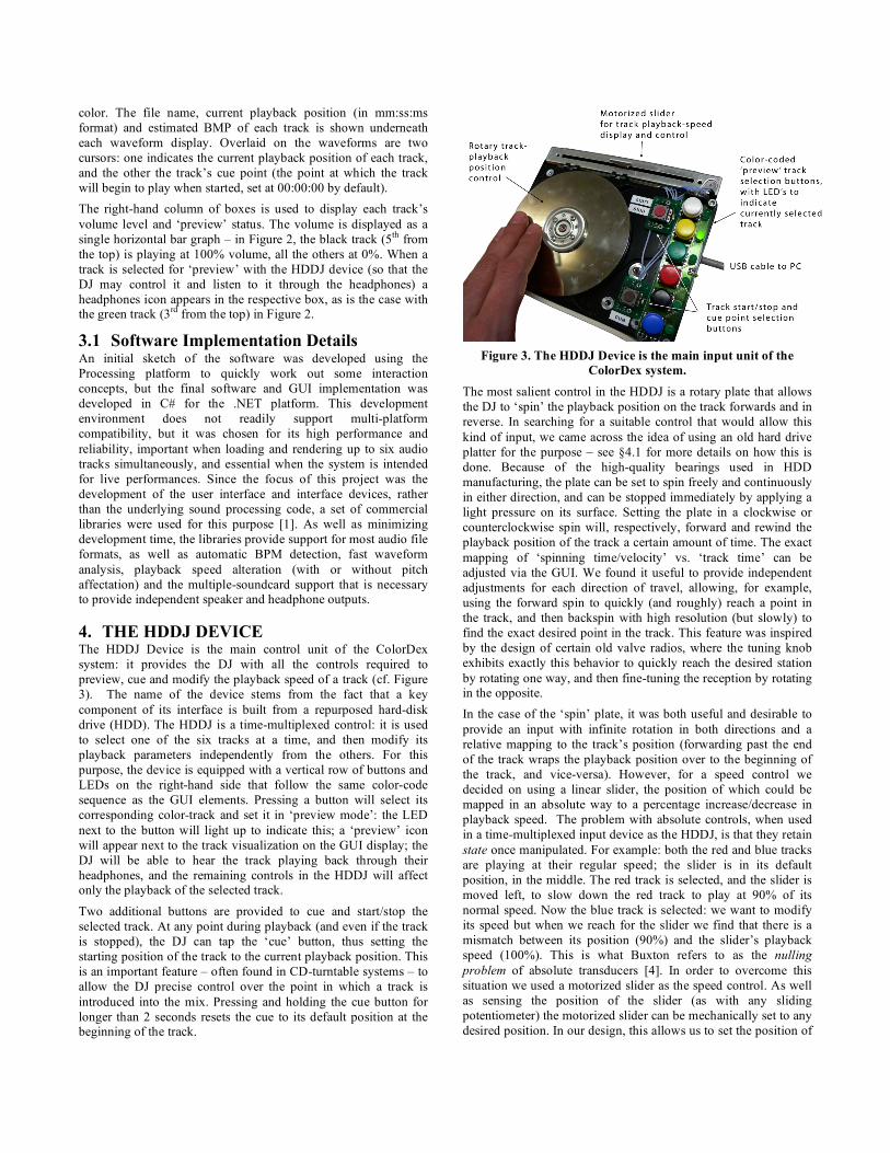
4. THE HDDJ DEVICE The HDDJ Device is the main control unit of the ColorDex system: it provides the DJ with all the controls required to preview, cue and modify the playback speed of a track (cf. Figure 3). The name of the device stems from the fact that a key component of its interface is built from a repurposed hard-disk drive (HDD). The HDDJ is a time-multiplexed control: it is used to select one of the six tracks at a time, and then modify its playback parameters independently from the others. For this purpose, the device is equipped with a vertical row of buttons and LEDs on the right-hand side that follow the same color-code sequence as the GUI elements. Pressing a button will select its corresponding color-track and set it in ‘preview mode’: the LED next to the button will light up to indicate this; a ‘preview’ icon will appear next to the track visualization on the GUI display; the DJ will be able to hear the track playing back through their headphones, and the remaining controls in the HDDJ will affect only the playback of the selected track.
Two additional buttons are provided to cue and start/stop the selected track. At any point during playback (and even if the track is stopped), the DJ can tap the ‘cue’ button, thus setting the starting position of the track to the current playback position. This is an important feature – often found in CD-turntable systems – to allow the DJ precise control over the point in which a track is introduced into the mix. Pressing and holding the cue button for longer than 2 seconds resets the cue to its default position at the beginning of the track.
Figure 3. The HDDJ Device is the main input unit of the
ColorDex system. The most salient control in the HDDJ is a rotary plate that allows the DJ to ‘spin’ the playback position on the track forwards and in reverse. In searching for a suitable control that would allow this kind of input, we came across the idea of using an old hard drive platter for the purpose – see §4.1 for more details on how this is done. Because of the high-quality bearings used in HDD manufacturing, the plate can be set to spin freely and continuously in either direction, and can be stopped immediately by applying a light pressure on its surface. Setting the plate in a clockwise or counterclockwise spin will, respectively, forward and rewind the playback position of the track a certain amount of time. The exact mapping of ‘spinning time/velocity’ vs. ‘track time’ can be adjusted via the GUI. We found it useful to provide independent adjustments for each direction of travel, allowing, for example, using the forward spin to quickly (and roughly) reach a point in the track, and then backspin with high resolution (but slowly) to find the exact desired point in the track. This feature was inspired by the design of certain old valve radios, where the tuning knob exhibits exactly this behavior to quickly reach the desired station by rotating one way, and then fine-tuning the reception by rotating in the opposite. In the case of the ‘spin’ plate, it was both useful and desirable to provide an input with infinite rotation in both directions and a relative mapping to the track’s position (forwarding past the end of the track wraps the playback position over to the beginning of the track, and vice-versa). However, for a speed control we decided on using a linear slider, the position of which could be mapped in an absolute way to a percentage increase/decrease in playback speed. The problem with absolute controls, when used in a time-multiplexed input device as the HDDJ, is that they retain state once manipulated. For example: both the red and blue tracks are playing at their regular speed; the slider is in its default position, in the middle. The red track is selected, and the slider is moved left, to slow down the red track to play at 90% of its normal speed. Now the blue track is selected: we want to modify its speed but when we reach for the slider we find that there is a mismatch between its position (90%) and the slider’s playback speed (100%). This is what Buxton refers to as the nulling problem of absolute transducers [4]. In order to overcome this situation we used a motorized slider as the speed control. As well as sensing the position of the slider (as with any sliding potentiometer) the motorized slider can be mechanically set to any desired position. In our design, this allows us to set the position of

the slider to a position that accurately represents the currently selected track’s playback speed. Following the previous example, as soon as the blue track was selected, the slider would have jumped from the left to its middle position – correctly displaying the 100% playback speed of the newly selected track. As an added benefit the slider provides haptic display to the DJ, allowing them to feel, by touching the control and without needing to look at it, at what speed the selected track is playing.
4.1 Using a HDD as a spin-input control In searching for a suitable solution for continuous rotary input for our prototype, we realized the limited choices that exist: use cheap rotary encoders, and sacrifice the quality of tactility of use (it is not easy to find a cheap encoder that spins well) or buy expensive high-end equipment that feels good to use. While looking for inspiration amongst assorted junk in the lab, we came upon a broken hard disk drive with its case open. We admired the quality of the bearings in the motor that drives the disk plates, and wondered whether we could sample an output from it when it was spun by hand, in much the same way that an electric motor, when turned, acts as a dynamo and outputs a voltage. Some probing with an oscilloscope confirmed that weak analog waveforms are produced at the motor contacts when the HDD plates spin above a certain speed, which is easily attained in spinning the disk by hand. In our design, we used an op-amp in a comparator circuit in order to amplify and square the motor outputs, which can then be easily sampled by a PIC microcontroller (cf. Figure 4).
Figure 4. Using a HDD motor as a spin-sensor by sampling the
output of the motor contacts while the HDD disk is spun. While suitable for our requirements, the HDD solution does have some limitations: chiefly, it requires some amount of spin, above a certain threshold, for the motor to output measurable signals. As a result it is not possible to detect small ‘scratch’-like movements, and as such is not a replacement for a digital turntable. It is still well suited as a rotary input device that spins effortlessly and has a high tactility factor, and, as an upside, broken HDDs are free to use and easy to find. We have experimented with a number of different HDD models, and found that most are suitable for this purpose. The largest variation lies in how easy it is to open the case of some compared to others (Seagate HDDs, which often use plain Phillips screws in the casing, are recommended). Detailed
circuit diagrams, microcontroller code and step-by-step on how to appropriate HDDs as input devices will be made available online on the Instructables website [7].
4.2 HDDJ Implementation Details The HDDJ is implemented as an embedded device, with a Microchip PIC microcontroller with built-in support for serial-line emulation over USB. The microcontroller operates a continuous routine in which it polls the state of all eight buttons on the device, calculates the spin velocity/direction of the spin-plate based on the HDD motor outputs (cf. Figure 4), and samples the position of the slider potentiometer. Only when a change of state in any of the controls is detected, this information is communicated to the PC via proprietary ASCII-based serial protocol. In every poll cycle, the microcontroller program checks the status of the incoming serial-line buffer for control data from the PC. The HDDJ responds to commands to turn on or off any of its built-in LEDs, or to set the position of the motorized slider. In this way, the device, although self-contained, remains generic and independent from any particular ColorDex program logic, with the intention that it could be easily incorporated into a different system. A planned revision to the firmware will add support for the MIDI protocol over USB.
5. THE CUBIC CROSSFADER The Cubic Crossfader is the final piece of the ColorDex puzzle: a small handheld cube that allows the DJ to wirelessly control the volume of individual tracks, seamlessly crossfade between them and create mixed music.
Figure 5. The Cubic Crossfader for wirelessly mixing tracks.
Each of the cube’s faces is painted with one of the six colors that have been used to identify tracks in both the GUI and the HDDJ (cf. Figure 5). Note how each edge indicates the adjoining face-colors. This was a modification that was made after a very early trial, when it was discovered that it was otherwise difficult to remember the colors of the hidden faces. The color-edges provide an effective cognitive aid that solves that problem. Figure 6 illustrates how the Cubic Crossfader is used by the DJ to control volume levels and mix tracks. The volume level of any color-track is equivalent to the amount of the cube’s color-side(s) that face upwards. When the cube is placed flat on a table, only one side is be facing completely upwards and a single track plays at full volume. When the cube is rotated by 45 degrees on a single axis, two faces will be displayed in equal amounts to the DJ, who is looking at the cube downwards, from above. In this case, both those tracks would are at equal volume levels (50% each). When

the cube is stood perfectly vertically on a corner, three tracks are be playing, at 33% volume each. These values are not stepped: a smooth rotation of the cube results in a smooth and gradual crossfade between adjacent tracks.
Figure 6. Crossfading between tracks by revealing different proportions of the cube’s colored faces, as seen by the DJ from
above. The selection of a cube shape for a crossfader object, and the way in which its orientation is mapped to volume levels, are not arbitrary choices. When the cube sits flat on a surface, it translates to having a single track play at full volume. In a DJ’ing situation, it is desirable that this is the default state of the crossfader – in a mix DJ’ing performance, most of the time only one track is playing. It is only during song transitions or mixes that the crossfader needs to be manipulated, and at those points it would be ‘in hand,’ in any case.
Another advantage of using the whatever-is-on-top-is-the-volume-level mapping, is that, although awkward to explain on paper, in practice it is almost intuitive, and more importantly, it is unambiguous. ‘Left,’ ‘right’, ‘behind’ and ‘forward’ are all relative to the observer, and as such can all too easily lead to confusion. A ‘down-side’ is hard too look at, unless the cube is held overhead, leaving the ‘up-side’ as the most useful for our purposes. Almost by coincidence, and due to the force of gravity, it is these changes in latitudinal orientation of an object that can be most easily and robustly sensed (c.f §5.1, below). However, the choice of a cube does present some additional questions that need to be addressed. There are two possible limitations that stem from that fact that firstly, in a cube, all sides cannot be displayed to the DJ simultaneously, and secondly, not all sides are adjoining. With the current mapping, the first limitation places a limit on how many tracks can be mixed at any one time. This is not necessarily a problem for our system: mixing even two tracks properly is hard work, and we are satisfied that our system allows the DJ to experiment with mixing ‘only’ up to three tracks. The second limitation can potentially be more of an issue: if the DJ cannot mix just any three tracks, they must then be able to know, or remember somehow, which tracks can be mixed together and which not. This could potentially result an undesirable cognitive overload at a time when quick thinking and decision-making are essential. The cube provides strong cognitive clues as to which tracks can be mixed together – any colors that adjoin each other will work. The problem lies more in using the Cubic Crossfader in conjunction with the GUI, which presents the tracks as a list. In this case, our solution was to carefully order the tracks in the GUI in such a way that any two tracks that follow each other in the list can be mixed together, with ‘blue’ wrapping around to ‘white’. Even if looking only at the GUI when planning a mix sequence, it is easy to tell that a mix between ‘red’ and
‘black’ is possible, but a crossfade between ‘yellow’ and ‘red’ cannot be achieved smoothly (these two colors will be found in opposite faces of the cube).
5.1 Using a 3D accelerometer to determine cube-orientation Acceleration sensors, or accelerometers, are small, cheap, robust, and consume relatively little power. As the name implies, accelerometers sense changes in velocity along an axis of movement. Due to the force of the Earth’s gravity, as well as any acceleration we may be subject to by moving around, we constantly experience an acceleration of 9.8 m/s2, or 1G, towards the center of the planet. This allows accelerometers to be used as accurate tilt-sensors: a stationary accelerometer with its sensing-axis placed horizontally to the ground will read a value of 0G, while one with its sensing axis aligned vertically will read a value of +1G, or -1G, depending on which way up it is oriented.
Figure 7. Sample training data to calibrate cube orientation.
‘Face’ refers to the currently top-facing side of the cube. Nowadays it is easy to get hold of 3D accelerometers, which are effectively three single axis accelerometers arranged at orthogonal angles to each other within a single IC package. Figure 7 shows some actual data from the 3D accelerometer used in the Cubic Crossfader and that was used in a calibration procedure (where the ColorDex GUI asks the DJ to ‘Place the Cubic Crossfader with the RED side UP, then click OK’). This procedure is repeated for all of the cube faces until the program has collected sensor readings for each of the six orientations. Notice that, for each pair of opposing faces (they are numbered as they would be on a die) one of the sensor readings shows an extreme change from +1G in one case, to -1G in the other. To determine the orientation of each face, it is this ‘extreme’ sensor reading that is taken into account, i.e. sensor X for faces 1 and 6; sensor Y for faces 2 and 5, and sensor Z for faces 3 and 4. As face 1 is rotated latitudinally, away from the top towards a lateral position, the readings for sensor X will gradually decrease, tending towards 0G. If the cube continues to be rotated in this way, the sensor reading will drop even further, tending towards -1G, meaning that face 6 is now surfacing to the top position (and, conversely, face 1 is heading for the bottom). In this way, having previous knowledge of how the faces are arranged in respect to the sensor axis, it is simple to calculate the current orientation of the cube. A more elegant and versatile approach has been introduced by Van Laerhoven et al. in [10], where, by applying a maximum likelihood estimation using multivariate Gaussians on the sensor readings, it is possible to train the cube not only to recognize its orientation, but also

gestures performed with it such as ‘shaking,’ ‘twisting’ and ‘knocking’.
Since the accelerometers are also susceptible to the forces resulting in – for example – shaking the Cubic Crossfader back and forth, subjecting the cube to tangential forces will have an audible repercussion on the track’s volume levels. Small unintentional vibrations, caused by regular manipulation of the Crossfader when mixing tracks, can be filtered out (see §5.2, below). However, we find it interesting to consider the avenues a DJ might explore in using the Crossfader when it is understood how the sensing technology works, and how it may be (mis)appropriated to generate new and unexpected results: shaking it, swinging it around on a string or even throwing it around the audience would all have a distinct effect, possibly interesting, on the music mix that is being played.
5.2 Cubic Crossfader Implementation Details The Cubic Crossfader prototype uses a 3-axis ADXL from Analog Devices, with a sensing range of ±2G, and PWM output. The sensor output is continuously sampled at 100Hz by a PIC microcontroller, and the data is smoothed using a using moving-window average algorithm that eliminates the small-scale vibrations experienced when holding the device with shaky hands, but without generating a perceptible ‘damping’ or delay in response time. In order to reduce power consumption, data is transmitted to the PC only when the variance on the sensor data stream exceeds a set threshold. A Linkmatik 2.0 “Serial-over-Bluetooth” module is used for wirelessly transmitting data to the ColorDex software on the PC. Calibration and calculation of the cube orientation based on the sensor data takes place within the core ColorDex program. The PIC microcontroller is more than powerful enough to perform these calculations on board, but, as with the HDDJ device, this was a design choice was made to maintain the device implementation as application-independent as possible.
6. DISCUSSION AND FUTURE WORK The ColorDex system, from initial conception to the current prototype implementation, has undergone a number of changes based on the feedback of a number of professional and bedroom mix-DJ’s. The most important change made to the initial design was the addition of the start/stop and cue buttons to the HDDJ device. Previously these functions had been accessible only through the GUI, requiring the DJ to shift their focus between touch-screen/mouse and HDDJ. Apart from browsing for and selecting tracks (for which a point-and-click GUI is better suited than any additional device we could introduce) the resulting design allows the DJ to distribute their attention and manual control effectively between the DJ components: gaze directed towards the GUI, dominant hand on the HDDJ preparing tracks for mixing, and the non-dominant hand coping well with the actions of holding and rotating the cube to perform crossfades.
A number of DJ’s have experimented with the device in an informal situation, and have on the whole responded favorably to the system, particularly to the engaging and entertaining factor they consider it would add to the performance – both for the DJ (“this is really fun to use” was mentioned more than once) as for the audience (“people would freak out if they saw this: it is so Minority Report” was the comment from one DJ, referring to a sci-fi Hollywood movie famous for the futuristic interfaces it portrays).
At the time of writing, only a single live trial has been conducted at a semi-public party where the first author, an amateur music-mixer, was asked to DJ. Due to admittedly mediocre beatmaching skills, creating successful 2-way mixes was a challenge in itself. However, once a 2-track mix was in place, the effort of introducing a third element was surprisingly not any harder. Once three tracks were beatmatched and playing in synchronicity, it was very entertaining to be able to seamlessly bring elements of each in and out of the mix by simply rotating the cube in a conical motion. The wireless feature of the Cubic Crossfader also added a new participatory aspect to the performance: allowing the DJ to wander out from behind the desk and engage with the audience while retaining some control over the mix. Another notable benefit was the ability to ‘lay out’ a mix sequence, a few tracks in advance. The two difficulties that came out of the trial are, one: it is hard to see the colored cube under party-lighting conditions; and two: continuous Bluetooth transmission consumes a lot of power, draining the 500mAh batteries after 3 hours. A new design iteration on the Cubic Crossfader will address these issues: the first by adding colored lights to the faces of the cube, and the second by revising the firmware to incorporate adaptive sensor sampling and wireless transmission rates to maximize battery life.
7. ACKNOWLEDGMENTS This research was supported by the UK Engineering and Physical Sciences Research Council as part of the Equator IRC (grant GR/N15986/0), and by the Ministry of Economic Affairs of the Netherlands as part of the Smart Surroundings project (contract 03060).
8. REFERENCES [1] Andersen, T.H., Mixxx: Towards Novel DJ Interfaces. In
Proceedings of the NIME’03. Montreal, Canada. 2003.
[2] AudioDJStudio for .NET. MultiMediaSoft http://www.audiodjstudio.com
[3] Brewster, B. and Broughton, F. How to DJ (Properly): The Art and Science of Playing Records. Bantam Press. 2006.
[4] Buxton, W. There’s More to Interaction than Meets the Eye: Some Issues in Manual Input. In Norman, D. A. Draper, S. W. (Eds.), User Center System Design: New Perspectives on Human Computer-Interaction . 1986.
[5] Beamish, T., Maclean, K., and Fels, F. Manipulating Music: Multimodal Interaction for DJs. In Proceedings of CHI’04. 2004.
[6] Beamish, T., Maclean, K., van del Doel, K., and Fels, F. D’Groove: A Haptic Turntable for Digital Audio Control. In Proceedings of the 2003 International Conference on Auditory Display, Boston. 2003.
[7] Instructables: Step-by-step project instructions. http://www.instructables.com
[8] Lippit, T.M. Realtime Sampling System for the Turntablist Version 2: 16padjoystickcontroller. In Proceedings o NIME’04. Hamamatsu, Japan. 2004.
[9] Hansen, K.F., Bresin, R. Mapping strategies in DJ scratching. In Proceedings of NIME’06. 2006.
[10] Van Laerhoven, K,.Villar, N., Schmidt, A., Kortuem, G. and Gellersen. H. Using an Autonomous Cube for Basic Navigation and Input. In Proceedings of ICMI/PUI 2003.


![[blank verso] - Welcome to Lancaster EPrints - Lancaster …eprints.lancs.ac.uk/72417/1/Introduction_Final.docx · Web viewThis volume critically considers the manner in which post-dictatorial](https://img.dokumen.tips/doc/110x75/5aa17e857f8b9a436d8bae53/blank-verso-welcome-to-lancaster-eprints-lancaster-viewthis-volume-critically.jpg)