Embed Size (px)
Citation preview
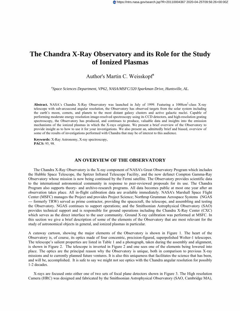
The Chandra X-Ray Observatory and its Role for the Study of Ionized Plasmas
Author's Martin C. Weisskopfa
aSpace Sciences Department, VP62, NASA/MSFC/320 Sparkman Drive, Huntsville, AL.
Abstract. NASA’s Chandra X-Ray Observatory was launched in July of 1999. Featuring a 1000cm2-class X-ray telescope with sub-arcsecond angular resolution, the Observatory has observed targets from the solar system including the earth’s moon, comets, and planets to the most distant galaxy clusters and active galactic nuclei. Capable of performing moderate energy resolution image-resolved spectroscopy using its CCD detectors, and high-resolution grating spectroscopy, the Observatory has produced, and continues to produce, valuable data and insights into the emission mechanisms of the ionized plasmas in which the X-rays originate. We present a brief overview of the Observatory to provide insight as to how to use it for your investigations. We also present an, admittedly brief and biased, overview of some of the results of investigations performed with Chandra that may be of interest to this audience.
Keywords: X-Ray Astronomy, X-ray spectroscopy, PACS: 95, 98.
AN OVERVIEW OF THE OBSERVATORY
The Chandra X-Ray Observatory is the X-ray component of NASA's Great Observatory Program which includes the Hubble Space Telescope, the Spitzer Infrared Telescope Facility, and the now defunct Compton Gamma-Ray Observatory whose mission is now being continued by the Fermi satellite. The Observatory provides scientific data to the international astronomical community in response to peer-reviewed proposals for its use. The Chandra Program also supports theory- and archive-research programs. All data becomes public at most one year after an observation takes place. All in-flight calibration data are available immediately. NASA's Marshall Space Flight Center (MSFC) manages the Project and provides Project Science; Northrup Grumman Aerospace Systems (NGAS --- formerly TRW) served as prime contractor, providing the spacecraft, the telescope, and assembling and testing the Observatory. NGAS continues to support operations; and the Smithsonian Astrophysical Observatory (SAO) provides technical support and is responsible for ground operations including the Chandra X-Ray Center (CXC) which serves as the direct interface to the user community. Ground X-ray calibration was performed at MSFC. In this section we give a brief description of some of the elements of the Observatory that are most relevant for the study of astronomical objects in general, and ionized plasmas in particular.
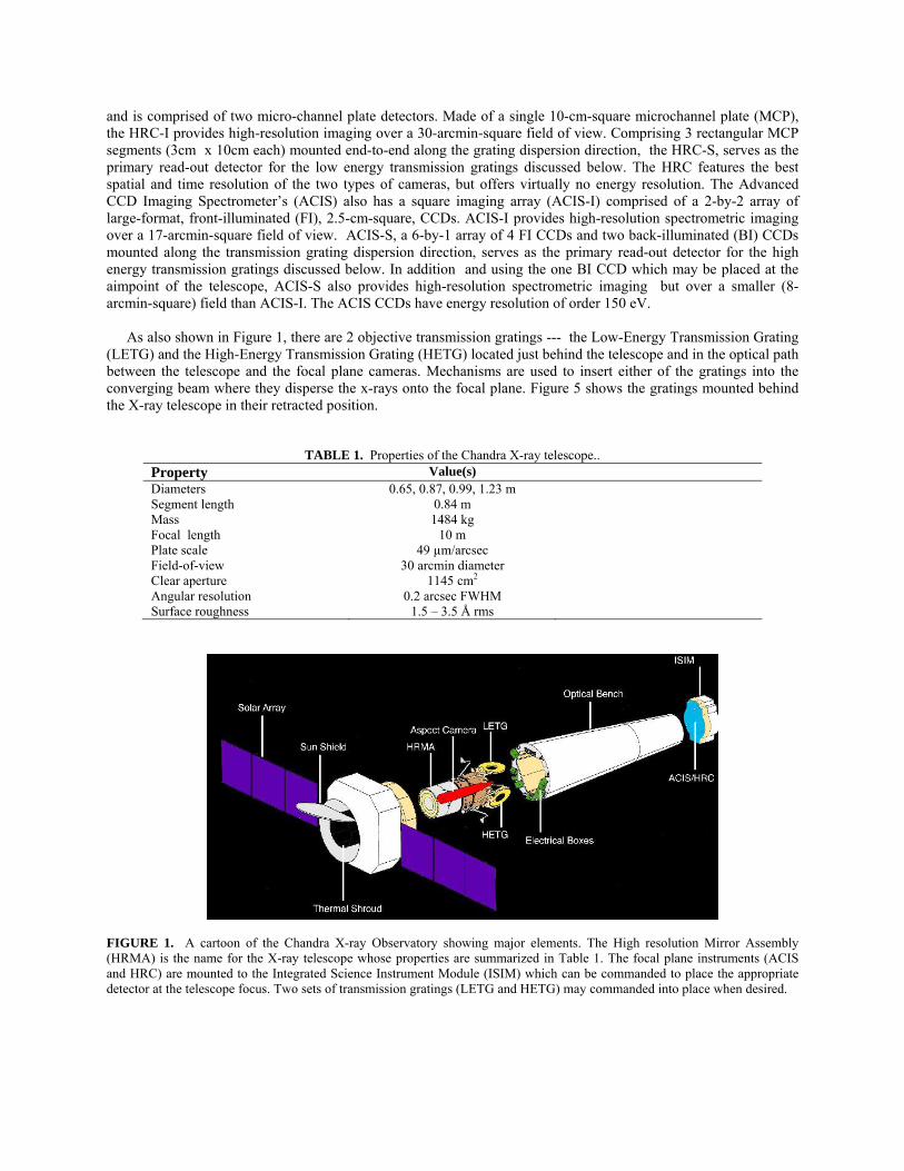
A cutaway cartoon, showing the major elements of the Observatory is shown in Figure 1. The heart of the Observatory is, of course, its optics made of four concentric, precision-figured, superpolished Wolter-1 telescopes. The telescope’s salient properties are listed in Table 1 and a photograph, taken during the assembly and alignment, is shown in Figure 2. The telescope is inverted in Figure 2 and one sees one of the elements being lowered into place. The optics are the principal reason why the Observatory is unique, both in comparison to previous X-ray missions and to currently planned future ventures. It is also this uniqueness that facilitates the science that has been, and will be, accomplished. It is safe to say we might not see optics with the Chandra angular resolution for possibly 1-2 decades.
X-rays are focused onto either one of two sets of focal plane detectors shown in Figure 3. The High resolution Camera (HRC) was designed and fabricated by the Smithsonian Astrophysical Observatory (SAO, Cambridge MA),
https://ntrs.nasa.gov/search.jsp?R=20110004367 2020-04-25T09:56:26+00:00Z
and is comprised of two micro-channel plate detectors. Made of a single 10-cm-square microchannel plate (MCP), the HRC-I provides high-resolution imaging over a 30-arcmin-square field of view. Comprising 3 rectangular MCP segments (3cm x 10cm each) mounted end-to-end along the grating dispersion direction, the HRC-S, serves as the primary read-out detector for the low energy transmission gratings discussed below. The HRC features the best spatial and time resolution of the two types of cameras, but offers virtually no energy resolution. The Advanced CCD Imaging Spectrometer’s (ACIS) also has a square imaging array (ACIS-I) comprised of a 2-by-2 array of large-format, front-illuminated (FI), 2.5-cm-square, CCDs. ACIS-I provides high-resolution spectrometric imaging over a 17-arcmin-square field of view. ACIS-S, a 6-by-1 array of 4 FI CCDs and two back-illuminated (BI) CCDs mounted along the transmission grating dispersion direction, serves as the primary read-out detector for the high energy transmission gratings discussed below. In addition and using the one BI CCD which may be placed at the aimpoint of the telescope, ACIS-S also provides high-resolution spectrometric imaging but over a smaller (8-arcmin-square) field than ACIS-I. The ACIS CCDs have energy resolution of order 150 eV.
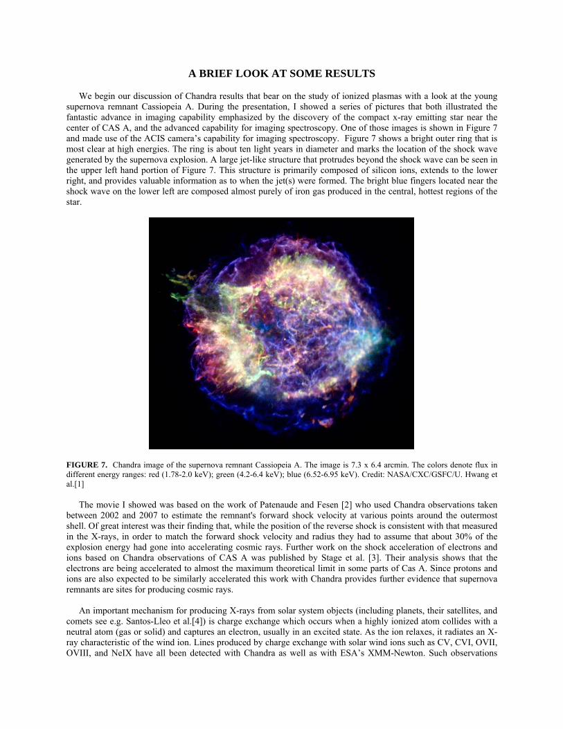
As also shown in Figure 1, there are 2 objective transmission gratings --- the Low-Energy Transmission Grating (LETG) and the High-Energy Transmission Grating (HETG) located just behind the telescope and in the optical path between the telescope and the focal plane cameras. Mechanisms are used to insert either of the gratings into the converging beam where they disperse the x-rays onto the focal plane. Figure 5 shows the gratings mounted behind the X-ray telescope in their retracted position.
TABLE 1. Properties of the Chandra X-ray telescope.. Property Value(s) Diameters 0.65, 0.87, 0.99, 1.23 m Segment length 0.84 m Mass 1484 kg Focal length 10 m Plate scale 49 µm/arcsec Field-of-view 30 arcmin diameter Clear aperture 1145 cm2 Angular resolution 0.2 arcsec FWHM Surface roughness 1.5 – 3.5 Å rms
FIGURE 1. A cartoon of the Chandra X-ray Observatory showing major elements. The High resolution Mirror Assembly (HRMA) is the name for the X-ray telescope whose properties are summarized in Table 1. The focal plane instruments (ACIS and HRC) are mounted to the Integrated Science Instrument Module (ISIM) which can be commanded to place the appropriate detector at the telescope focus. Two sets of transmission gratings (LETG and HETG) may commanded into place when desired.
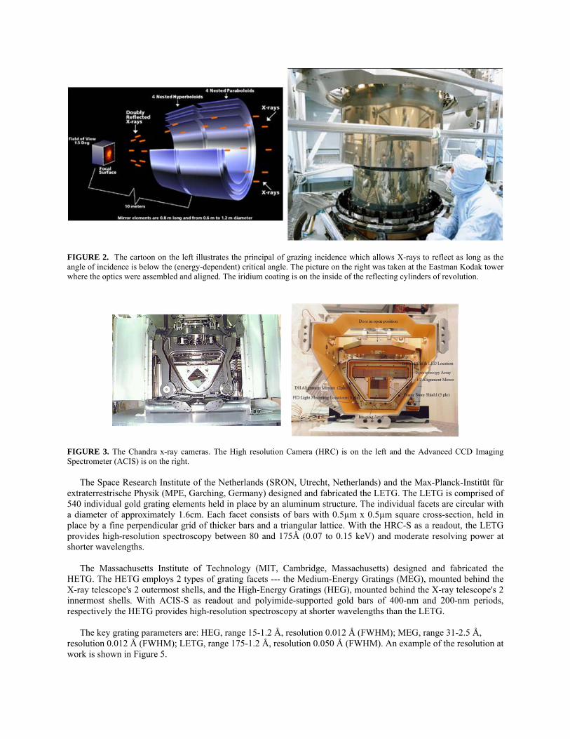
FIGURE 2. The cartoon on the left illustrates the principal of grazing incidence which allows X-rays to reflect as long as the angle of incidence is below the (energy-dependent) critical angle. The picture on the right was taken at the Eastman Kodak tower where the optics were assembled and aligned. The iridium coating is on the inside of the reflecting cylinders of revolution.
FIGURE 3. The Chandra x-ray cameras. The High resolution Camera (HRC) is on the left and the Advanced CCD Imaging Spectrometer (ACIS) is on the right.
The Space Research Institute of the Netherlands (SRON, Utrecht, Netherlands) and the Max-Planck-Institüt für
extraterrestrische Physik (MPE, Garching, Germany) designed and fabricated the LETG. The LETG is comprised of 540 individual gold grating elements held in place by an aluminum structure. The individual facets are circular with a diameter of approximately 1.6cm. Each facet consists of bars with 0.5µm x 0.5µm square cross-section, held in place by a fine perpendicular grid of thicker bars and a triangular lattice. With the HRC-S as a readout, the LETG provides high-resolution spectroscopy between 80 and 175Å (0.07 to 0.15 keV) and moderate resolving power at shorter wavelengths.
The Massachusetts Institute of Technology (MIT, Cambridge, Massachusetts) designed and fabricated the HETG. The HETG employs 2 types of grating facets --- the Medium-Energy Gratings (MEG), mounted behind the X-ray telescope's 2 outermost shells, and the High-Energy Gratings (HEG), mounted behind the X-ray telescope's 2 innermost shells. With ACIS-S as readout and polyimide-supported gold bars of 400-nm and 200-nm periods, respectively the HETG provides high-resolution spectroscopy at shorter wavelengths than the LETG.
The key grating parameters are: HEG, range 15-1.2 Å, resolution 0.012 Å (FWHM); MEG, range 31-2.5 Å,
resolution 0.012 Å (FWHM); LETG, range 175-1.2 Å, resolution 0.050 Å (FWHM). An example of the resolution at work is shown in Figure 5.
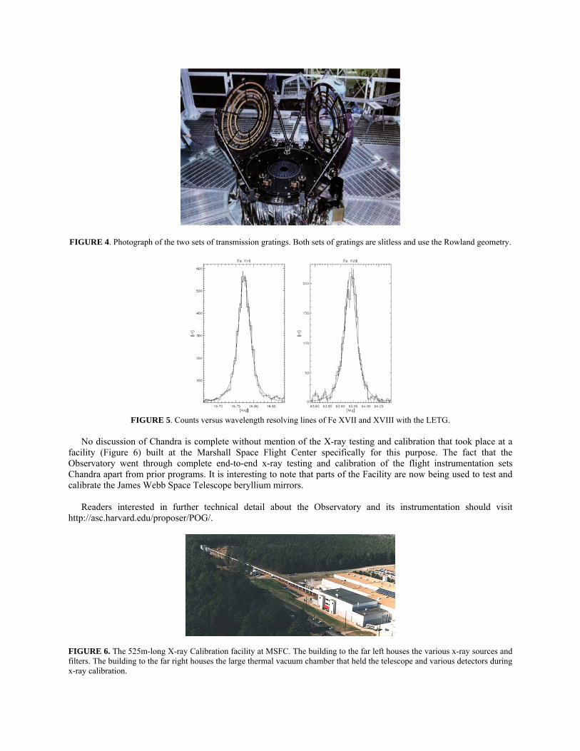
FIGURE 4. Photograph of the two sets of transmission gratings. Both sets of gratings are slitless and use the Rowland geometry.
FIGURE 5. Counts versus wavelength resolving lines of Fe XVII and XVIII with the LETG.
No discussion of Chandra is complete without mention of the X-ray testing and calibration that took place at a
facility (Figure 6) built at the Marshall Space Flight Center specifically for this purpose. The fact that the Observatory went through complete end-to-end x-ray testing and calibration of the flight instrumentation sets Chandra apart from prior programs. It is interesting to note that parts of the Facility are now being used to test and calibrate the James Webb Space Telescope beryllium mirrors.
Readers interested in further technical detail about the Observatory and its instrumentation should visit
http://asc.harvard.edu/proposer/POG/.
FIGURE 6. The 525m-long X-ray Calibration facility at MSFC. The building to the far left houses the various x-ray sources and filters. The building to the far right houses the large thermal vacuum chamber that held the telescope and various detectors during x-ray calibration.
A BRIEF LOOK AT SOME RESULTS
We begin our discussion of Chandra results that bear on the study of ionized plasmas with a look at the young supernova remnant Cassiopeia A. During the presentation, I showed a series of pictures that both illustrated the fantastic advance in imaging capability emphasized by the discovery of the compact x-ray emitting star near the center of CAS A, and the advanced capability for imaging spectroscopy. One of those images is shown in Figure 7 and made use of the ACIS camera’s capability for imaging spectroscopy. Figure 7 shows a bright outer ring that is most clear at high energies. The ring is about ten light years in diameter and marks the location of the shock wave generated by the supernova explosion. A large jet-like structure that protrudes beyond the shock wave can be seen in the upper left hand portion of Figure 7. This structure is primarily composed of silicon ions, extends to the lower right, and provides valuable information as to when the jet(s) were formed. The bright blue fingers located near the shock wave on the lower left are composed almost purely of iron gas produced in the central, hottest regions of the star.
FIGURE 7. Chandra image of the supernova remnant Cassiopeia A. The image is 7.3 x 6.4 arcmin. The colors denote flux in different energy ranges: red (1.78-2.0 keV); green (4.2-6.4 keV); blue (6.52-6.95 keV). Credit: NASA/CXC/GSFC/U. Hwang et al.[1]
The movie I showed was based on the work of Patenaude and Fesen [2] who used Chandra observations taken between 2002 and 2007 to estimate the remnant's forward shock velocity at various points around the outermost shell. Of great interest was their finding that, while the position of the reverse shock is consistent with that measured in the X-rays, in order to match the forward shock velocity and radius they had to assume that about 30% of the explosion energy had gone into accelerating cosmic rays. Further work on the shock acceleration of electrons and ions based on Chandra observations of CAS A was published by Stage et al. [3]. Their analysis shows that the electrons are being accelerated to almost the maximum theoretical limit in some parts of Cas A. Since protons and ions are also expected to be similarly accelerated this work with Chandra provides further evidence that supernova remnants are sites for producing cosmic rays.
An important mechanism for producing X-rays from solar system objects (including planets, their satellites, and comets see e.g. Santos-Lleo et al.[4]) is charge exchange which occurs when a highly ionized atom collides with a neutral atom (gas or solid) and captures an electron, usually in an excited state. As the ion relaxes, it radiates an X-ray characteristic of the wind ion. Lines produced by charge exchange with solar wind ions such as CV, CVI, OVII, OVIII, and NeIX have all been detected with Chandra as well as with ESA’s XMM-Newton. Such observations

have shown that charge-exchange plays an important role in the production of X-rays from solar system objects, and, conversely, can provide valuable information about the solar wind. For more on the role of Chandra for understanding charge-exchange in the Solar system, see the paper by Wargelin [5] in these proceedings.
Although the X-ray luminosity of stellar coronae is but a small fraction of the bolometric luminosity, X-ray observations have proven to be good indicators of magnetic activity and the effectiveness of stellar magnetic dynamos. High-resolution X-ray spectroscopy with the objective gratings on Chandra (and XMM-Newton) have enabled measurement of many spectral lines—including resolved multiplets—and, in some cases, line profiles and line shifts. These measurements provide critical diagnostics of densities, temperatures, and composition of hot coronal plasmas [6]. Figure 8 gives one an insight as to the evolution of solar-like stars of different ages as determined through x-ray measurements [7]. The relative intensity of OVIII to O VII provides a visual indication of the temperature of the plasma, the larger the ratio, the higher the temperature. Younger solar-like stars have higher temperatures and luminosities.
FIGURE 8. Chandra LETG spectra of solar-like stars of different ages. Credit: P.Testa private communication.
One of my favorite examples of the richness of Chandra spectra comes from the study by Watanabe et al. [8] of the high-mass X-ray binary system Vela X-1 obtained with the Chandra HETGS. A spectrum, shown in Figure 9, is most unusual displaying almost all charge states of silicon. Not only unusual, these data guided modeling of the fluorescing material --- dense, near-neutral clouds embedded in a tenuous, highly ionized wind which itself must be highly inhomogeneous to sustain the low ionization stages.
One of the major current problems in astrophysics is that, at low redshift, at most 50% of the baryonic matter in the local Universe can be accounted for by stars, gas in galaxies or clusters of galaxies, or low redshift Ly-α absorption systems [9]. Large scale simulations, e.g. Figure 10, predict that most of the “missing baryons” are distributed as filamentary structures between galaxies in the form of a Warm-Hot Intergalactic Medium (WHIM) with temperatures in the range 0.1-10 MK [10]. Uultraviolet absorption lines detected in background quasar spectra reveal its existence [11], the majority of the WHIM is expected to be in a temperature region that can be studied only in X-rays. Recently, a deep Chandra observations [12], when combined with the earlier XMM-Newton and Chandra observations, give a 4σ detection of the OVII K-α line shown in the inset to Figure 10.

Figure 9. X-ray spectrum from the high-mass X-ray binary Vela X-1. Fluorescence lines from silicon showing almost all charge states from S1 II to Si X, in addition to the He-like Si XIII triplet and the Si XIV Lyman series. Credit: F. Paerels, private communication.
Figure 10. Composite picture illustrating one approach for the study of the WHIM, namely searching for more local absorption features in the spectrum of a distant quasar. The spectrum in the upper left spectra for H2356-309 shows absorption by local OVII (z=0) and more distant OVII (z=0.03). Credit the Chandra Science Center and T. Fang. In closing I leave the reader with two examples (Figures 11 and 12) that show the richness and complexity of Chandra high-resolution X-ray spectra that I think speak for themselves in illustrating their necessity and utility for understanding astrophysical plasmas.
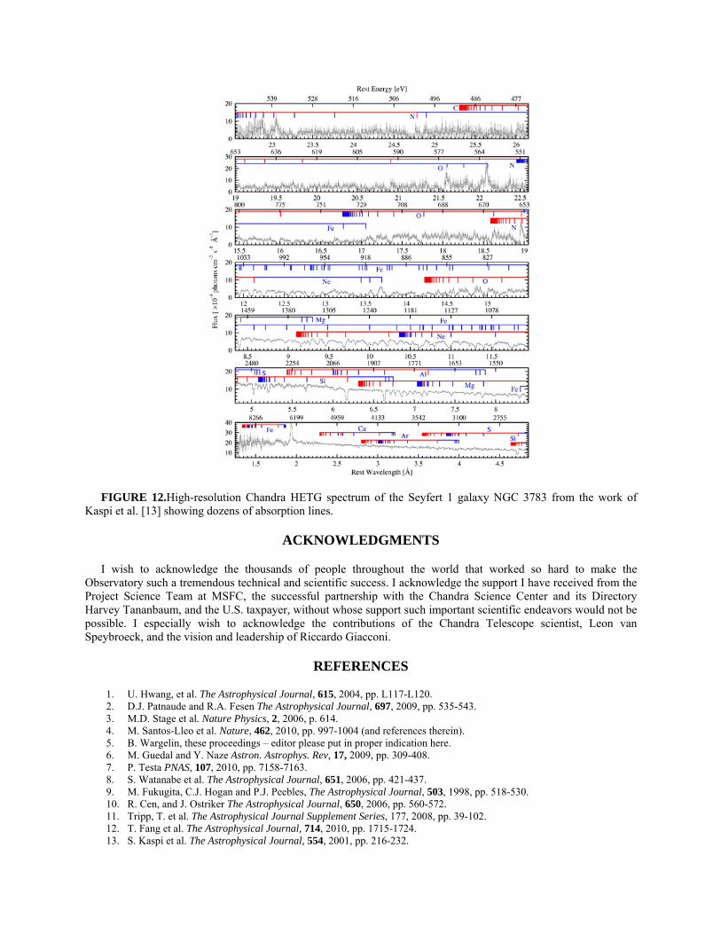
FIGURE 12.High-resolution Chandra HETG spectrum of the Seyfert 1 galaxy NGC 3783 from the work of Kaspi et al. [13] showing dozens of absorption lines.
ACKNOWLEDGMENTS
I wish to acknowledge the thousands of people throughout the world that worked so hard to make the Observatory such a tremendous technical and scientific success. I acknowledge the support I have received from the Project Science Team at MSFC, the successful partnership with the Chandra Science Center and its Directory Harvey Tananbaum, and the U.S. taxpayer, without whose support such important scientific endeavors would not be possible. I especially wish to acknowledge the contributions of the Chandra Telescope scientist, Leon van Speybroeck, and the vision and leadership of Riccardo Giacconi.
REFERENCES
1. U. Hwang, et al. The Astrophysical Journal, 615, 2004, pp. L117-L120. 2. D.J. Patnaude and R.A. Fesen The Astrophysical Journal, 697, 2009, pp. 535-543. 3. M.D. Stage et al. Nature Physics, 2, 2006, p. 614. 4. M. Santos-Lleo et al. Nature, 462, 2010, pp. 997-1004 (and references therein). 5. B. Wargelin, these proceedings – editor please put in proper indication here. 6. M. Guedal and Y. Naze Astron. Astrophys. Rev, 17, 2009, pp. 309-408. 7. P. Testa PNAS, 107, 2010, pp. 7158-7163. 8. S. Watanabe et al. The Astrophysical Journal, 651, 2006, pp. 421-437. 9. M. Fukugita, C.J. Hogan and P.J. Peebles, The Astrophysical Journal, 503, 1998, pp. 518-530. 10. R. Cen, and J. Ostriker The Astrophysical Journal, 650, 2006, pp. 560-572. 11. Tripp, T. et al. The Astrophysical Journal Supplement Series, 177, 2008, pp. 39-102. 12. T. Fang et al. The Astrophysical Journal, 714, 2010, pp. 1715-1724. 13. S. Kaspi et al. The Astrophysical Journal, 554, 2001, pp. 216-232.