Embed Size (px)
Citation preview
THE CASE FOR DEVS IN NETWORKING M&S: UPLOAD USER COLLABORATION IN MOBILE NETWORKS USING COORDINATED MULTIPOINT
Misagh Tavanpour
Jan MikhailGabriel Wainer
Gary Boudreau
Department of Systems and Computer Engineering
Ericsson Canada
Carleton University
Ottawa, ON, Canada
{misagh, janmikhail, gwainer}@sce.carleton.ca
ABSTRACT
Future mobile networks should provide high data rate services for their customers regardless of their location. This is a challenging task, specifically for the users in the edge of the cell’s area. To overcome this problem, Long Term Evolution Advanced introduced Coordinated Multi-Point. Upload User Collaboration (UUC), presented here, can be combined with CoMP to enhance the upload performance of cell-edge users. This research presents a real-world use of Discrete Event System specifications for modeling mobile networks, and a practical case study with industrial relevance (algorithms, based on the DEVS studies, were patented by Ericsson Inc. for commercialization). The study compares three approaches: UUC, CoMP, and a non-cooperative algorithm. The simulations show that UUC provides significant improvements to the cell-edge users’ upload performance, and it reduces the time required to upload a file.
Keywords: CoMP, Upload, LTE-Advanced, DEVS
1 INTRODUCTION
The advent of Smartphone changed mobile networks considerably. In 2014, the number of Smartphone subscriptions and monthly data traffic per Smartphone was 2.6 billion and 1 GB respectively. These numbers will pass 6.3 billion and 8.9 GB in 2021 (Cerwall 2016). The users should have high data rates regardless of their location in the covered area. This is not an easy task especially for the cell-edge users. Due to their longer distance from the cell center, their signal experience more attenuation. Moreover, their closeness to other neighbor cells leads to higher level of interference (Tavanpour et al. 2015a). One promising solution to cell-edge users’ problem is called Coordinated MultiPoint (CoMP). It refers to a set of Base Stations (BS, also called evolved Node B, eNBs) that are coordinated dynamically and work jointly to improve the cell-edge users’ performance (Tavanpour et al. 2013).
Here, we introduce an advanced algorithm called Upload User Collaboration (UUC), to improve the cell-edge performance while users upload large files. This method works in a distributed CoMP architecture. According to UUC, the User Equipment (UE) that owns the file (called owner UE) divides it into a number of pieces at the beginning of the upload. Then, the owner UE starts the upload by transferring pieces to the group of eNBs that are coordinated dynamically. At the same time, it can ask for help from neighboring UEs, and let them upload some of the pieces directly using Device-To-Device (D2D) communications, and different pieces of a file can be uploaded through multiple communication channels. To study the performance of the UUC algorithm we used the Discrete EVent System specification (DEVS) formalism, which showed to be a flexible and effective technique to model UUC, CoMP and a non-cooperative algorithm. The hierarchical nature of DEVS allowed us to capture precise information from different levels of the model. Moreover, we could reuse models to study different approaches in a SpringSim-TMS/DEVS 2017, April 23-26, Virginia Beach, VA, USA©2017 Society for Modeling & Simulation International (SCS)

Tavanpour, Mikhail, Wainer and Boudreau
short time (Tavanpour et al. 2013). The simulation results showed that UUC improves the users upload performance considerably, and it reduces the average upload time. In addition, the simulations showed that UUC provides services that are more consistent as the users travel around the cell borders.
2 BACKGROUND
Future mobile networks will need to support large numbers of UEs with high data rate demands. High data rates are relatively easy to maintain when one is close to the eNB, but as distances increase, there is a lower signal strength and a higher interference level from the neighboring eNBs. LTE-Advanced (LTE-A) is a promising standard proposed for Fourth Generation (4G) systems which can deal with these issues. The International Mobile Telecommunications-Advanced refers to set of requirement that the International Telecommunication Union issued for what is marketed as 4G. One of the objectives of IMT-Advanced and IMT-2020 (a roadmap for the development of 5G technologies) is to provide a consistent service for the UEs regardless of their location. Different forecasts predict that the LTE-A will have the highest Compound Annual Growth Rate (CAGR) among all standards in 2014-2020 (Cerwall 2015). LTE-A employs a number of technologies including CoMP to overcome the transmission barriers and to support high data rates. CoMP refers to a set of eNBs (BSs) that are coordinated jointly and dynamically in which the eNBs form coordination sets to manage interference (Lu et al. 2012). By coordinating and combining signals from multiple eNBs, mobile users can have high quality and consistent performance when they require high bandwidth. This is supported regardless of their distance from the cell center. CoMP has some drawbacks as well: it needs a backhaul with higher capacity and lower latency, and it has overhead on the backhaul as well as more complexity to the mobile system. Based on how the control information is shared among the transmission points, there are two CoMP implementations: centralized and distributed. In the latter, the UEs share their channel status with their serving eNBs and they forward this information to the other eNBs that could be in the coordination set (Tavanpour et al. 2013).
Some recent research focused on different methods to enhance the users’ performance in 4G systems. In (Malandrino et al. 2015), the authors propose using Heterogeneous Networks (HetNets) and D2D networks to deal with data traffic. However, to benefit from opportunities offered by HetNets and D2D, an intelligent resource-allocation technique is required. Therefore, they propose an interference-aware resource-scheduling algorithm. In (Kantarci 2015), the authors propose content caching: the content of the servers is replicated at locations closer to the users. The authors propose merging content caching and wireless networks. Also, they propose a method to reduce energy budget of UEs in the upload process. In (Orsino et al 2015; Militano et al. 2015a), the authors use D2D in a single LTE-A cell area to enhance the upload for users with poor links to the eNB. The UE uses a D2D channel to send its data to another UE with a high-quality uplink channel, and the latter UE uploads the data as its own. In (Militano et al. 2015b), the authors extend the previous technique and they use multi hop D2D communication for data uploading toward the eNB. The UE can use D2D channel to send its data to a second UE, which sends it to a third that has better uplink channel, which transfers the data to the eNB.
We used DEVS for M&S of our proposed algorithm, which showed to be an adequate tool to deal with the complexity of the models (Tavanpour et al. 2013; Tavanpour et al. 2015a). DEVS is based on system theory concepts, and it provides a precise methodology for representing models, and an abstract description of the system of interest. Based on DEVS, a real system can be defined as a composition of atomic and coupled components, which is hierarchical in nature. Atomic models are the basic blocks and a set of two or more interconnected atomic models can form the coupled models. A coupled model itself can be composed of atomic or coupled models (Tavanpour et al. 2013).
3 THE UUC ALGORITHM
In this section, we discuss the UUC algorithm, which tries to improve the cell-edge users upload in dis-tributed CoMP. UUC focuses on enhancing the UEs upload process by using the upload power of multi-
Tavanpour, Mikhail, Wainer and Boudreau
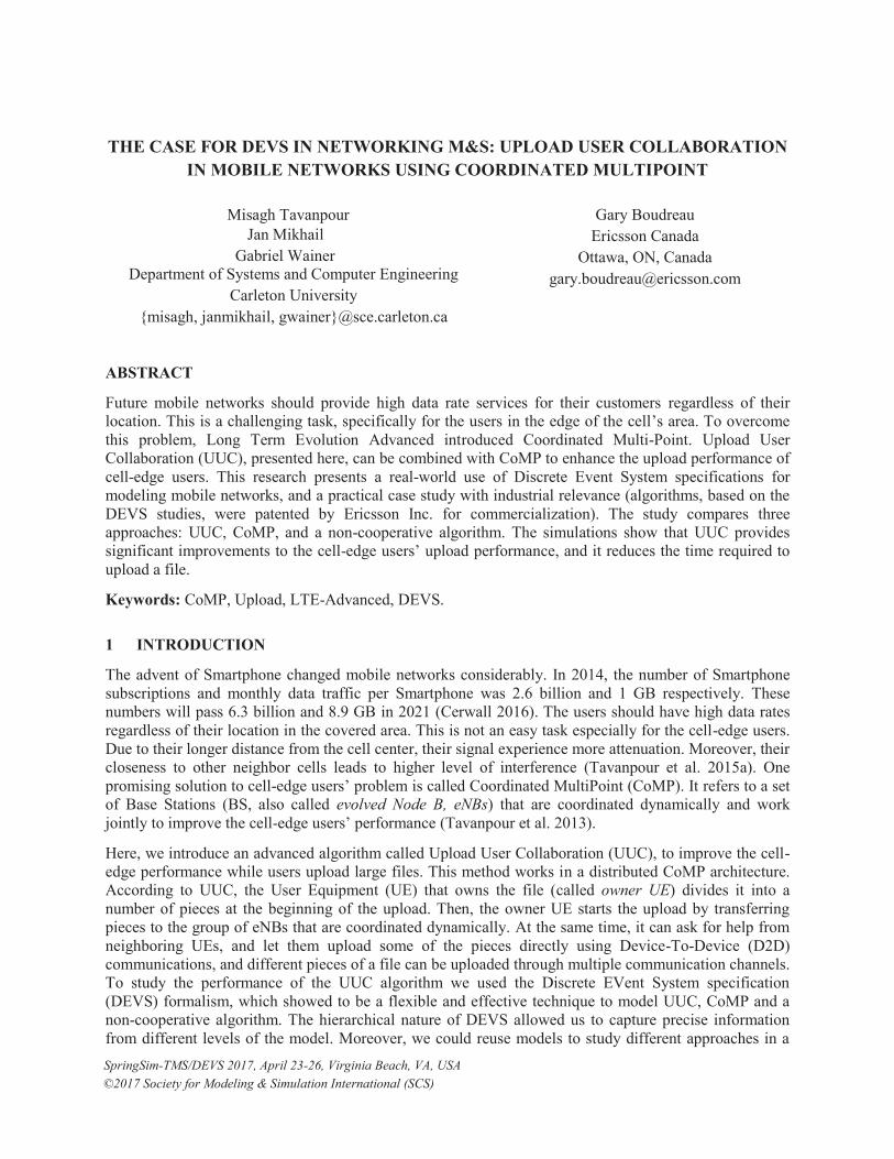
ple users that are close to each other. Let us assume that there is an owner UE in a mobile network (UE1 in Figure 1) that wants to upload a file, and there are three eNBs in its range. The eNBs form a coordina-tion set, with eNB1 acting as the serving eNB. In addition, there is a number of nearby UEs. The upload process starts when owner UE1 divides the file into pieces (left side of Figure 1) and sends an Upload Request message to the eNBs in its range. At the same time, it queries the neighboring UEs to see if they are willing to help with the upload process (Upload Assistance Request message). After receiving a Handshake from the eNBs in the coordination set, the owner UE starts uploading the pieces. In addition, if neighboring UEs want to help (called helper UEs), they send a Confirmation message to the owner UE, which assigns a number of pieces to them, and it sends those pieces over D2D channels (this process hap-pens in parallel to the owner UE uploading pieces to the eNBs). In Figure 1, two helper UEs want to help the owner UE. After receiving their portion of the file, the helper UEs upload those pieces. To do so, they use their own communication channels with the eNBs in the coordination set, and the owner UE uploads the rest of the pieces (right side of Figure 1). From the eNBs’ perspective, they start an upload with the owner UE based on the defined messages for UUC. During the upload process, they may receive control messages from potential helper UEs showing that they want to assist the owner UE. After performing the required steps to initiate an upload process, the communication channels between these helpers UEs and their supporting eNBs are established, and they will be able to upload the owner UE pieces as their own. The eNBs forward the received pieces to the Mobility Management Entity (MME). Finally, the MME uses all the pieces to reconstruct the original file. This method tries to speed up the upload process of the UEs regardless of their position in the cell.
UE1 cut downs the data file into pieces
123456789101112131415161718192021
UE1
eNB2
eNB1
eNB3
Owner UE assigns a number of pieces to each of the helper UEs
123456789101112131415161718192021
UE1
eNB2
eNB1
eNB3
Owner UE and the Helper UEs upload different pieces of a same data file at a same time
UE1
18192021
121314151617
1234567891011
Figure 1: UE1 with 3 eNBs in its coordination set.
3.1 UUC messages definition
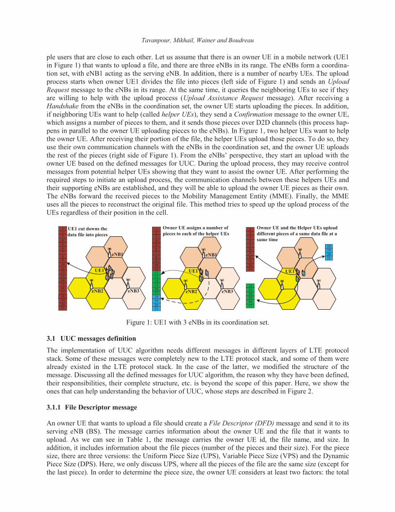
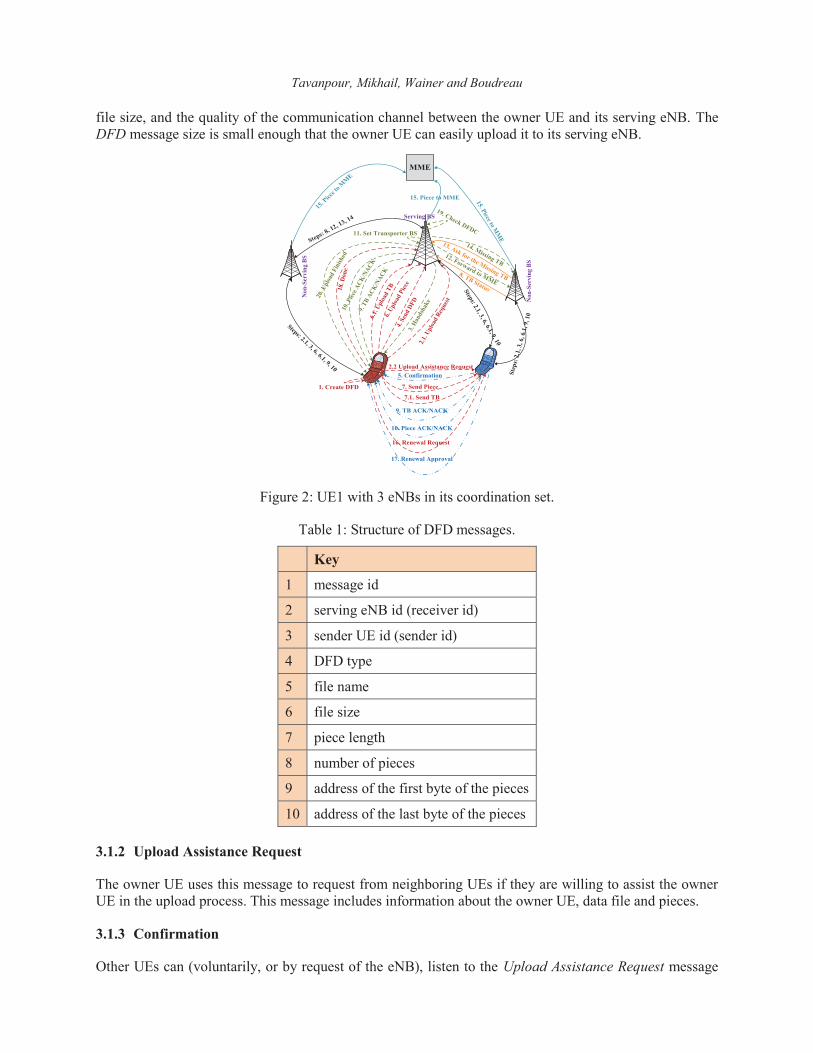
The implementation of UUC algorithm needs different messages in different layers of LTE protocol stack. Some of these messages were completely new to the LTE protocol stack, and some of them were already existed in the LTE protocol stack. In the case of the latter, we modified the structure of the message. Discussing all the defined messages for UUC algorithm, the reason why they have been defined, their responsibilities, their complete structure, etc. is beyond the scope of this paper. Here, we show the ones that can help understanding the behavior of UUC, whose steps are described in Figure 2.
3.1.1 File Descriptor message
An owner UE that wants to upload a file should create a File Descriptor (DFD) message and send it to its serving eNB (BS). The message carries information about the owner UE and the file that it wants to upload. As we can see in Table 1, the message carries the owner UE id, the file name, and size. In addition, it includes information about the file pieces (number of the pieces and their size). For the piece size, there are three versions: the Uniform Piece Size (UPS), Variable Piece Size (VPS) and the Dynamic Piece Size (DPS). Here, we only discuss UPS, where all the pieces of the file are the same size (except for the last piece). In order to determine the piece size, the owner UE considers at least two factors: the total
Tavanpour, Mikhail, Wainer and Boudreau
file size, and the quality of the communication channel between the owner UE and its serving eNB. The DFD message size is small enough that the owner UE can easily upload it to its serving eNB.
Serving BS
Steps: 8, 12, 13, 14
Non
-Ser
ving
BS
MME
Steps: 2.1, 3, 6, 6.1, 9, 10
Step
s: 2
.1, 3
, 6, 6
.1, 9
, 10
Non
-Ser
ving
BS
11. Set Transporter BS
19. Check DFDC
14. Missing TB12. Forward to MME
3. Han
dsha
ke
20. U
ploa
d Fi
nish
ed10
. Piec
e ACK
/NACK
9. TB
ACK/N
ACK1. Create DFD
4. Se
nd D
FD
6. Upl
oad
Piec
e
6.1. U
ploa
d TB18
. Don
e
2.1. U
ploa
d Req
uest
2.2 Upload Assistance Request
7. Send Piece
7.1. Send TB
16. Renewal Request
5. Confirmation
10. Piece ACK/NACK
9. TB ACK/NACK
17. Renewal Approval
8. TB Status
13. Ask for the Missing TB
15. Piece to MM
E
15. P
iece t
o MME
Steps: 2.1, 3, 6, 6.1, 9, 10
15. Piece to MME
Figure 2: UE1 with 3 eNBs in its coordination set.
Table 1: Structure of DFD messages.
Key
1 message id
2 serving eNB id (receiver id)
3 sender UE id (sender id)
4 DFD type
5 file name
6 file size
7 piece length
8 number of pieces
9 address of the first byte of the pieces
10 address of the last byte of the pieces
3.1.2 Upload Assistance Request
The owner UE uses this message to request from neighboring UEs if they are willing to assist the owner UE in the upload process. This message includes information about the owner UE, data file and pieces.
3.1.3 Confirmation
Other UEs can (voluntarily, or by request of the eNB), listen to the Upload Assistance Request message

Tavanpour, Mikhail, Wainer and Boudreau
from the owner UE. If a candidate helper UE is capable of assisting, it transmits the Confirmation message (Table 2). This message notifies the owner UE about the maximum data size that the helper UE offers to help in upload, and other information. The decision made by the UEs on whether to become a potential helper can depend on a number of factors, including the communication channel condition, the remaining battery life, security limitations, and service provider’s rewards for assisting other UEs.
Table 2: Simplified structure of ‘Confirmation’ message
Key
1 message id
2 receiver UE id (receiver id)
3 sender UE id (sender id)
4 file name
5 max data size offer to help in upload
6 preferred piece size
…
3.1.4 Piece
Upon receiving a Confirmation message from a helper UE, the owner needs to decide if it wants to use that helper UE. This decision can be made based on different factors including the quality of the communication channel between the owner UE and the helper UE, and the number of helper UEs. Upon selection of the helper UEs, the owner UE uses the Piece message (in Table 3) to send a number of pieces to each of the helper UEs. The number of pieces is determined based on the information in the Confirmation message. The owner UE keeps track of the pieces that are assigned to each helper UE (it receives feedback from the serving eNB regarding these pieces). After establishing a channel with the eNBs, both the owner UEs and helpers UEs send their pieces to the eNBs in their range. When the eNBs receive a Piece message, they save the required information about the received pieces. This information helps the eNBs avoid future uploading of the same data by other UEs (within a limited period). In our proposal, a data piece is a unit of data used in the upper layers of LTE protocol. However, the RLC layer dynamically segments the pieces (that it receives from PDCP layer) into a number of segments (known as RLC PDUs) based on the channel condition. The MAC layer then uses the RLC PDUs and MAC headers to create transport blocks (TBs) based on the channel condition.
3.1.5 TB Status
Upon receiving a TB of a Piece message from the UEs, the non-serving eNBs automatically send a TB status message to the serving eNB of the owner UE. This message includes a field with the status of the TB reception at the non-serving eNB. Therefore, the serving eNB of the owner UE has all the information about status of the TBs’ reception of all the pieces that the owner UE and helper UEs upload to the eNBs of their coordination set. The serving eNB uses this information to avoid retransmissions and to determine which eNB in the coordination set should forward the received piece to the MME.
3.1.6 Forward to MME
The serving eNB (BS) is responsible to select an eNB (from now on called transporter eNB) to send a fully received piece to the MME. The Forward to MME message asks the transporter eNB to forward the piece. If the serving eNB is selected as the transporter of a piece, there is no need for this message. This message includes a field that shows if the transporter eNB has the all the TBs of the piece. In that case,
Tavanpour, Mikhail, Wainer and Boudreau
the transporter eNB has all the TBs of a piece and it can send the piece to the MME. If not, the transporter eNB should wait for the missing TBs from other eNBs. The list of those TBs can be found in this message as well. Upon receiving those missing TBs, the transporter eNB can send the piece to the MME.
Table 3: Simplified structure of the ‘Piece’ message for a UE-to-UE communication
Key
1 message id
2 helper UE id (receiver id)
3 owner UE id (sender id)
4 file name
5 piece number
6 piece size
7 data load
…
3.1.7 DFD Complements (DFDC)
During the upload, the non-serving eNBs of the coordination set send control information of the received pieces to the serving eNB. The serving eNB inserts this information into a DFD Complements (DFDC) list. This message structure keeps track of the pieces upload status, and it can be used for checking the reception of all the pieces at end of the upload.
4 MODELING OF THE MOBILE NETWORK IN DEVS
We developed a DEVS model for an LTE network to study the performance of UUC. The top-level model is similar to the one introduced in (Tavanpour et al. 2015a), and it contains one atomic model (LogManager) and four coupled models (UEManager, BSManager, MME, and Atmosphere). The Atmosphere coupled model is used to simplify the interconnections between UEs and BSs (each BS coupled model is directly connected to neighboring BS through individual links). The MME coupled model, models the simplified behavior of an MME entity. LogManager, UEManager, and BSManager are identical to those in (Tavanpour et al. 2015a). However, the structure of their sub-models (including both the coupled and the atomic models) are mostly different from the sub-models in (Tavanpour et al. 2015a). Some of these differences are discussed in more detail in the rest of this section.
In comparison to the DEVS model in (Tavanpour et al. 2015a), the new extended DEVS model was de-signed to be flexible, in such a way that the basic functions of LTE systems are separated from the behav-ior of the algorithm being tested. Moreover, the layers of the LTE protocol stack have been implemented as separate model entities, allowing the behavior of an algorithm to be modeled in more detail at each layer. Each UE and BS coupled model composed of a number of atomic and coupled sub models. The structure of the UE coupled model is shown in Figure 3. Each of the four layers in the user plane of the LTE protocol stack (PDCP, RLC, MAC and PHY layers) are implemented as separate entities. Moreover, an application layer entity (UEAPPLayer) was added to initiate the file upload process at the beginning of the simulations. Each layer is associated with an instance of a UEQueue to queue up the incoming mes-sages. A UETimer atomic model is used to issue a “tick” signal at regular intervals. The signal is used by the UEPHYLayer atomic model to synchronize the processing of incoming messages with LTE’s Trans-mission Time Intervals (TTIs) of one millisecond (Dahlman, Parkvall and Skold 2013). The UE coupled model also contains coupled models UEFilter and UETransmitter. UEFilter is used to filter messages re-

Tavanpour, Mikhail, Wainer and Boudreau
ceived by the UE model from the Atmosphere through the fromATM input port. Since these messages are broadcasted, each receiver (UE or BS) need to filter them based on their intended destination. The UEFilter coupled model is composed of a UEFilterQueue and UEFilterProcessor. The UETransmitter coupled model is used to synchronize the outgoing messages sent by the UE with LTE’s TTI. It queues the outgoing messages and sends them at 1-ms intervals according to the scheduled resources available. BS coupled models have a similar structure. However, they also receive messages from the MME and neighboring BSs. The model was designed to accommodate any number of neighboring BSs, and there-fore, allows it to be adapted to support heterogeneous network deployments. Similarly, BS coupled mod-els have matching outputs ports to the MME model as well as each of its n neighboring BSs. The atomic sub-models are each defined in a separate C++ class in the CD++ toolkit. These C++ classes define the implementations of the internal, external and output functions, according to the DEVS formal definition. Figure 4 shows a class diagram for the model’s atomic classes.
in
req
inreq
toUpper
toLower
out
in
req
inreq
toUpper
out
in
req
inreq
toUpper
out
in
req
inreq
toUpper
out
req
inreq
out
toLower
UEQ
ueue
UEQ
ueue
UEQ
ueue
UEQ
ueue
UEQ
ueue
toLowertoLower
inU
ETimer
out
toATM
UE
toATM
UETransmitterreq
req
UETransmitterQueUETransmitterPro inoutinout
out
fromA
TM
UEFilterreq
req
UEFilterQueueUEFilterProcessor inoutinout
in
UEPhysicalLayer
UEM
AC
Layer
UER
LCLayer
UEPD
CPLayer
UEA
PPLayer
Figure 3: Structure of the UE coupled model.
BSTr
ansm
itter
Que
ue
BSFi
lterP
roce
ssor
BSFi
lterQ
ueue
BSPH
YLa
yer
BSQ
ueue
BSTr
ansm
itter
Proc
esso
r
BSPD
CPL
ayer
BSR
LCLa
yer
BSM
AC
Laye
r
BSTi
mer
Mob
ility
Man
agem
entE
ntity
Proc
esso
r
Mob
ility
Man
agem
entE
ntity
Que
ue
LogM
anag
er
Atm
osph
ereP
roce
ssor
Atm
osph
ereQ
ueue
BSA
PPLa
yer
UET
rans
mitt
erQ
ueue
UEF
ilter
Proc
esso
r
UEF
ilter
Que
ue
UEP
HY
Laye
r
UEQ
ueue
UET
rans
mitt
erPr
oces
sor
UEP
DC
PLay
er
UER
LCLa
yer
UEM
AC
Laye
r
UET
imer
UEA
PPLa
yer
<abs
tract
>A
tom
ic
-sta
te: S
tate
# A
tom
ic (c
onst
strin
g&)
# in
itFun
ctio
n():
Mod
el#
exte
rnal
Func
tion(
cons
t Ext
erna
lMes
sage
&):
Mod
el#
inte
rnal
Func
tion(
cons
t Int
erna
lMes
sage
&):
Mod
el#
outp
utFu
nctio
n(co
nst I
nter
nalM
essa
ge&
): M
odel
# ho
ldIn
(con
st St
ate,
cons
t Tim
e): M
odel
# pa
ssiv
ate(
): M
odel
...
Figure 4: Simplified UML class diagram for the model’s atomic classes.
In the LTE DEVS model used to simulate UUC, we used the same propagation model from (Tavanpour et al. 2015a). The propagation model considered for D2D communication assumes outdoor-to-outdoor communication. Based on the channel models defined in a technical report (3GPP 2014), the path loss for a direct Line-of-Sight (LoS) and non- Line-of-Sight (NLoS) transmission between two UEs can be calculated using the following equations (Meinila et al. 2010).

Tavanpour, Mikhail, Wainer and Boudreau
where is the UE-to-UE separation distance (in m); is the operating carrier frequency for D2D transmissions (in MHz); and is the UE antenna height, calculated from the ground (in m). The NLoS path loss is offset by -5 dB to adapt the channel model for D2D communication. The probability of having a LoS transmission ( ) is used from (Kyosti et al. 2007) to select one of the previous two channel models to calculate the overall channel path loss ( ).
The channel path loss is then calculated using: (3GPP 2014), where is the free space path loss (Meinila et al. 2010).
Shadowing was implemented using a log-normally distributed random variable, . Moreover, a Rayleigh distributed random variable ( ) was used to model small-scale fading. The resulting propagation losses are combined like: . The received power is calculated using: . Finally, the data rate of the transmission link is calculated using the following equation (3GPP 2011).
We have also implemented a non-cooperative algorithm as well as Standard Joint Transmission CoMP in order to compare them with UUC. The former represents a simplistic upload model where a UE only communicates with its serving eNB. In the latter, multiple antennas that are geographically distributed at multiple eNB (or BS) sites receive the transmitted signal. This form of joint reception is usually referred to as receive diversity (Huiyu et al. 2012). The eNBs share these copies with the serving eNB (over X2 backhaul links) which, based on the signal-to-noise (SNR) ratio of the received signals, selects the signal with highest instantaneous SNR from the diversity branch (one of the receiver eNBs). This approach is referred to as Selection Combiner (Kong and Milstein 1999).
5 SIMULATION SCENARIO AND RESULTS
We conducted a number of system-level simulations to evaluate the potential performance gains of UUC with varying number of helper UEs, and compared it to a non-cooperative upload (referred to as ’Non-CoMP’), as well as a CoMP upload. This section presents two simulation scenarios whose results have 95% confidence interval. The simulations consider an urban area of 1875 m by 2165 m, served by nine eNBs. Each eNB covers a cell area with a 500-m radius. The operating carrier frequency is 900 MHz. All D2D communications operate on a carrier frequency of 2000 MHz (3GPP 2014). Shadowing for D2D transmissions was calculated using a standard deviation of 7 dB. The UE antenna height was 1.5 m.
In the first scenario we compared the performance of the three algorithms as a function of the distance between the UEs and their serving eNBs (BSs). The BS-UE separation distances were increased in increments of 50 m. In each simulation, the UEs were placed within a distance range of 10 m, starting with 100-110 m. In this scenario, we simulate the upload of ten files by ten owner UEs. In UUC simulations, the owner UE to helper UE distance is 10 m (a fixed distance to reduce the variability of the results). The size of the files to be uploaded by the owner UEs are selected based on a uniform
Tavanpour, Mikhail, Wainer and Boudreau
distribution between 30 and 60 MB. The piece size is 1 MB. For each UE-to-BS distance range, eight simulations were run as follows. In the first one, each owner UE only uploads the file to its serving eNBs using Non-CoMP. In the second one, each owner UE uploads their file to its coordination set of eNBs using the CoMP as described in the previous section. Note that the availability of multiple cooperating eNBs depends on the position of the UE within the cell, as well as the channel quality. In the following six simulations, the owner UEs upload their files using UUC with the help of one to six helper UEs, respectively. We will refer to these simulations as UUC-H1 to UUC-H6. The simulations run until all the files were uploaded by the UEs.
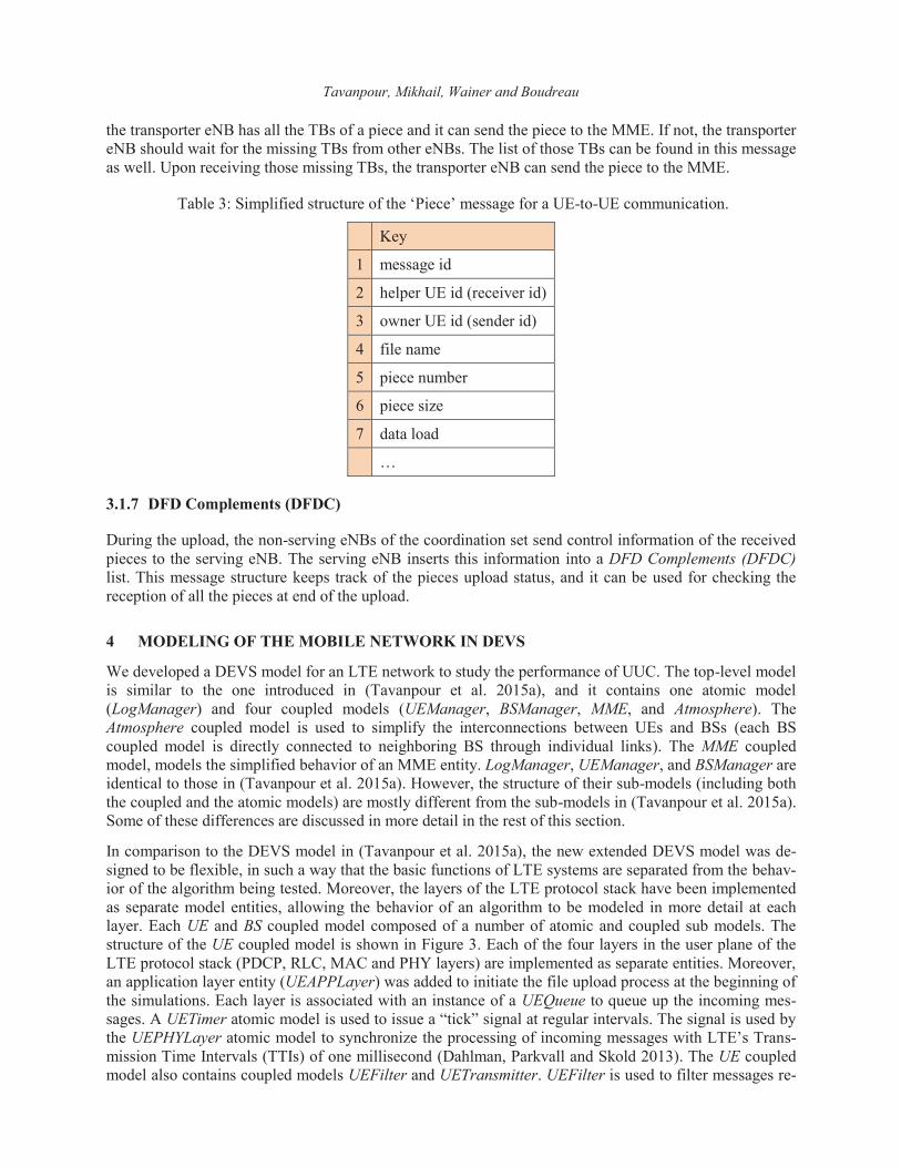
Figure 5 shows the average number of eNBs that participate in the upload versus the average distance of UEs from their serving eNBs. During the simulation, the owner UEs are able to upload pieces to the eNBs of their coordination set. Moreover, each helper UE participating in the upload process can upload pieces of the same file to the eNBs to their own coordination set. The number of eNBs in Figure 5 includes the eNBs that received file pieces from the owner UEs as well as helper UEs (even if the eNBs in the coordination sets of the owner and helper UEs overlap). For example, consider an owner UE uploading a file with the help of one helper UE. If the owner and helper UE share the same coordination set of three eNBs, the average total number of eNBs (or BSs) for that file would be six. We can see that while the UEs are at 305 m of less from their serving eNBs, Non-CoMP and CoMP behave identically, as expected (non-serving eNBs only join the coordination set if the average SNR is within 9 dB of the serving eNB’s average SNR, and therefore, the UE has to be relatively close the cell edges to communicate with multiple eNBs). At the cell edges, the UEs employing CoMP are able to upload pieces of their files to 2.44 eNBs (on average). Close to the cell center, each UE only communicates with its serving eNB. However, at the cell edges, UEs are able to communicate with multiple eNBs. Increasing the number of transmission channels that can be utilized in parallel for a file upload offers an opportunity to improve the overall performance for file uploads.
Figure 5: Average number of BSs per file vs. average distance from cell center (Scenario 1).
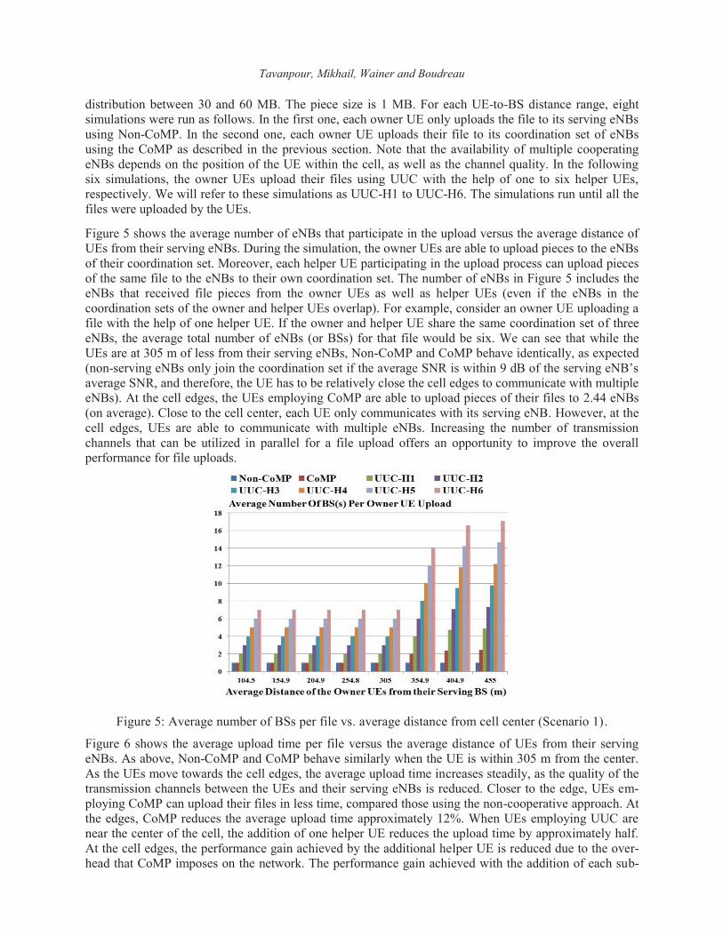
Figure 6 shows the average upload time per file versus the average distance of UEs from their serving eNBs. As above, Non-CoMP and CoMP behave similarly when the UE is within 305 m from the center. As the UEs move towards the cell edges, the average upload time increases steadily, as the quality of the transmission channels between the UEs and their serving eNBs is reduced. Closer to the edge, UEs em-ploying CoMP can upload their files in less time, compared those using the non-cooperative approach. At the edges, CoMP reduces the average upload time approximately 12%. When UEs employing UUC are near the center of the cell, the addition of one helper UE reduces the upload time by approximately half. At the cell edges, the performance gain achieved by the additional helper UE is reduced due to the over-head that CoMP imposes on the network. The performance gain achieved with the addition of each sub-

Tavanpour, Mikhail, Wainer and Boudreau
sequent helper UE is further reduced, since the files are shared with more helper UEs. For example, when the UEs are located around 104 m away from their serving eNBs, the addition of a third helper UE re-duces the average upload time by 22%, compared to the 31% reduction by the addition of a second helper UE. Near the cell center, the performance gain achieved by the addition of a fourth helper UE is out-weighed by the overhead of UUC, caused by the additional transmission of data between the owner UE and the helper UE. However, when the UEs are at the cell edges, performance gains can still be achieved with the assistance of six helper UEs.
Figure 6: Average upload time vs. average distance from serving eNB (Scenario 1).
The performance also depends on the size of the file. Small files incur in a large amount of overhead to set up the D2D communication channels. On the other hand, a relatively large file would make the overhead of setting up the D2D communication channels insignificant compared to the overall amount of time required to upload the file. To explore the effect of the file size on the performance of UUC, we conducted a simulation scenario focusing on cell-edge UEs that are placed randomly between 350-500 m from their serving eNBs. The owner UE to helper UE distance is 10 m. Figure 7 shows the average file upload time versus the file size for UEs employing each of the upload algorithms. This figure shows that the average time required to upload files increases linearly as the size of the files increases. CoMP offers around 11% reduction in the upload time, regardless of the file size, compared to the standard non-cooperative method. UUC further improves the upload performance for cell-edge UEs. The performance improvement depends on the availability of helper UEs. For example, owner UEs that use UUC with the assistance of one helper UE obtain an average of 48% reduction in the upload time, compared to UEs that utilize CoMP. Similarly, the assistance of a second helper UE reduces the upload time an average of 64.1% compared to CoMP. Increasing the number of helper UEs to four helper UEs further improves the effectiveness of UUC. However, the addition of the fifth helper UE only improves the upload performance when the files are sufficiently large. For small files in the order of 10 MB, increasing the number of helper UEs beyond three UEs has little to no effect on the upload performance, and, in some cases, the overhead of UUC increases the overall upload time. For files that are 30 MB or larger, the addition of the fifth helper UE further reduces the upload time (75% reduction on average, compared to CoMP). Beyond the fifth helper UEs, additional helper UEs provides insignificant improvement. In some cases, these additional helper UEs impose an overhead that is larger than the performance gains they provide, resulting in a lower overall performance.
6 CONCLUSION
We presented the Upload User Collaboration algorithm to improve the upload performance of UEs trying

Tavanpour, Mikhail, Wainer and Boudreau
to upload large files to a cellular LTE-A network. The algorithm allows these UEs to request assistance from neighboring UEs. The owner UEs divide the file into a number of pieces and shares the file pieces with neighboring UEs over Device-to-Device (D2D) communication links. The owner and helper UEs can then upload pieces of the file to the network simultaneously, on separate transmission channels. Moreover, the cell-edge UEs employ Coordinated MultiPoint Joint Transmission to communicate with multiple neighboring eNBs. We also presented a DEVS model for LTE networks that was used to simulate and compare the proposed algorithm to the traditional non-cooperative method, as well as the standard CoMP approach. The simulation results show that UUC promises significant improvements in the upload performance of UEs, regardless of their position within the cell, compared to the approaches (non-CoMP and CoMP). Considering the UEs mobility, further investigation is required to study the influence of the owner/helper UEs leaving their current host cell and changing their serving BS during the file upload. Also, we need to focus on the overhead that UUC imposes to the mobile network as well.
Figure 7: a) Average upload time vs. file size b) Zoom in on part of Figure 7.a
REFERENCES
3GPP. 2014, “Study on LTE device to device proximity services“.Technical Report No. 36.843, V12.0.0. Third Generation Partnership Project (3GPP).
3GPP. 2011, “Evolved Universal Terrestrial Radio Access (E-UTRA)“.Technical Report No. 36.942, V10.2.0. Third Generation Partnership Project (3GPP).
Cerwall, P. 2016. “On the pulse of the networked society”. Ericsson Mobility Report. Cerwall, P. 2015. “On the pulse of the networked society”. Ericsson Mobility Report. Dahlman, E., S. Parkvall and J. Skold. 2014. 4G: LTE/LTE-A for mobile broadband. 2nd ed. Academic
press, Elsevier. Huiyu, Y., Z. Naizheng, Y. Yuyu and P. Skov. 2012. “Performance evaluation of coordinated multipoint
reception in CRAN under LTE-Advanced uplink”. In proceedings of 7th International ICST Conference on Communications and Networking. China.
Kantarci, M. 2015. “Content caching in small cells with optimized uplink and caching power”. In pro-ceedings of Wireless Communication and Networking Conference. New Orleans, LA, USA.
Kong, N. and L. B. Milstein. 1999. “Average SNR of a generalized diversity selection combining scheme,” IEEE Communications Letters 3, no 3, pp 57–59.

Tavanpour, Mikhail, Wainer and Boudreau
Kyosti, P., J. Meinila, L. Hentila, Z. Zhao, T. Jasmsa, C. Schneider, M. Narandzic, M. Milojevic, A. Hong, J. Ylitalo, V. Holappa, M. Altossava, R. Bultitude, Y. Jong and T. Rautiainen. 2007. “WINNER II Channel Models”. Wireless World Initiative New Radio (WINNER).
Lu, X., S. Chen, W. Zhou and J. Song. 2012. “Analysis of Signaling Design in LTE-Advanced Coordi-nated Multipoint Transmission/Reception System”. In proceedings of IEEE Conference on Computer Science and Automation Engineering. China.
Malandrino, F., Z. Limani, C. Casetti and C. Chiasserini. 2015. “Interference-Aware Downlink and Up-link Resource Allocation in HetNets with D2D Support”. IEEE Transactions on Wireless Communi-cation 14, no 5, pp 2729-2741.
Meinila, J., P. Kyosti, L. Hentila, T. Jamsa, E. Suikkanen, E. Kunnari and M. Narandzic. 2010. “D5.3: WINNER+ Final Channel Models”. Wireless World Initiative New Radio (WINNER).
Militano, L., A. Orsino, G. Araniti, A. Molinaro, A. Iera and L. Wang. 2015a, “Efficient spectrum man-agement exploiting D2D communication in 5G systems”, Proceeding of IEEE International Sympo-sium on Broadband Multimedia Systems and Broadcasting. Ghent, Belgium.
Militano, L., A. Orsino, G. Araniti, A. Molinaro and A. Iera. 2015b, “A Constrained Coalition Formation Game for Multihop D2D Content Uploading”, IEEE Transaction on Wireless Communication 15, no 3, pp 2012-2024.
Orsino, A., L. Militano, G. Araniti, A. Molinaro and A. Iera. 2015. “Efficient Data Uploading Supported by D2D Communications in LTE-A Systems”. In proceedings of 21st European Wireless Conference. Budapest, Hungary.
Tavanpour, M., M. Moallemi, G. Wainer, J. Mikhail, G. Boudreau and R. Casselman. 2015a. “Data Up-load in LTE-A Mobile Networks by Using Shared Segmented Upload”. Journal of Networks 10, no 4, pp. 252-265.
Tavanpour, M., J. Mikhail, G. Wainer, G. Boudreau, H. Seyyedm Mahdi and R. Casselman. 2015b. “File Transfer by Mobile User Collaboration”. Patent Filing Reference P46444 WO1, 2015, PCT/IB2015/054524, USA.
Tavanpour, M., G. Wainer, G. Boudreau and R. Casselman. 2013. “DEVS-based Modeling of Coordinated Multipoint Techniques for LTE-A”. In proceedings of 16th Communications and Networking Symposium, San Diego, CA.
AUTHOR BIOGRAPHIES
MISAGH TAVANPOUR received his Ph.D. from Carleton University. His research interests include LTE-Advanced, Coordinated Multipoint, DEVS formalism and Network on Chips. His email address is [email protected].
JAN MIKHAIL received his master from Carleton University. His research interests include LTE-Advanced, Coordinated Multipoint and DEVS formalism. His email address is [email protected].
GABRIEL WAINER is a Professor at the department of Systems and Computer Engineering at Carleton University. His research interests include DEVS formalism, Real-Time modeling, Cellular models, parallel/distributed/web-based simulation and M&S methodologies and tools. His email address is [email protected].
GARY BOUDREAU is a LTE system architect at Ericsson Canada. He is a professional engineer with over 25 years of communications system engineering experience. He received his Ph.D. from Carleton University. His email address is [email protected].