Embed Size (px)
Citation preview
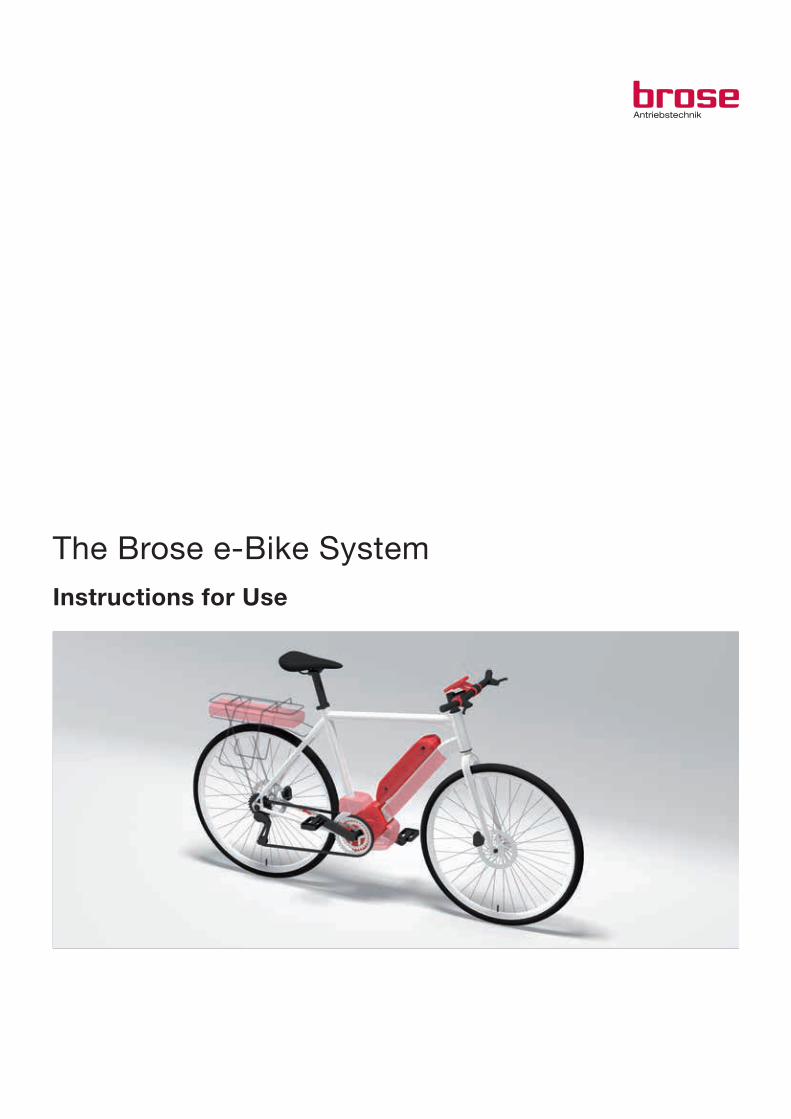
The Brose e-Bike SystemInstructions for Use

2
Instructions for Use of Brose e-Bike System
Reference number: BDA_BeBS_MY2014_en_v1.0

3
Table of contentsFigures ................................................................................................................. 4
Quick Start Instructions ........................................................................................ 6
Drive unit ............................................................................................................. 7
Display and control unit .......................................................................................10
Battery pack .......................................................................................................14
Battery charger ...................................................................................................18
Troubleshooting ...................................................................................................21
Your notes ..........................................................................................................23
4
1 2
A001-0
LIGHT
MEN
U
ON/OFF
1
3
2
A002-0
3 4
4
3
5
A003-0
LIGHT
MEN
U
ON/OFF
LIGHT
MENU
ON/OFF
876
1
A004-0
5 6
LIGHT
MEN
U
ON/OFF
14
12
15
13
11
9
10
1
A005-0
16
17
18
19
20
A006-0Figures

5
7 8
LIGHT
MEN
U
ON/OFF
1
22
21
A007-0
23
24
25
5 - 17 m
m
A008-0
9 10
30
2629
27
28
A009-0
31
26
A010-0
11 12
30
32
A011-0
36
32
33
35
34A012-0

6
This section summarizes for you all the important information and instructions enabling you to use your Brose e-Bike System as quickly as possible.
− Fully charge the battery pack (26) (see „Charging the
battery pack“ on page 19)
− Insert the battery pack (26) (see „[Fig. 10] Inserting/
removing the battery pack“ on page 15)
− Lock the battery pack key (29) (see Fig. 9 sowie „Lo-
cking/unlocking the battery pack key“ on page 15)
− Insert the display unit (1) (see „[Fig. 2] Inserting the
display unit“ on page 10)
− Activate the Brose e-Bike System using the LED but-
ton (28) on the battery pack (26) (see Fig. 9 and also
„Switching on the Brose e-Bike System“ on
page 11)
→ The display unit (1) activates automatically
− Select the assist level using the control unit (16) (see
Fig. 6 and also „Setting the assist level“ on page 12)
− The e-Bike is now ready to use.
Quick Start Instructions

7
Safety directions
− Please follow all safety directions and instructions
found in both these Instructions for Use and in all
other sets of instructions supplied with the e-Bike.
→ Not following these safety directions and instruc-
tions can lead to electric shocks, fires and/or seve-
re injuries.
− Keep these Instructions for Use safe for future refe-
rence.
− The term “battery pack” used in these Instructions for
Use equally relates to downtube-mounted battery
packs, rack-mounted battery packs and frame-integ-
rated battery packs.
− Never open the drive unit. It is maintenance-free and
may only be repaired by qualified experts using only
original spare parts.
→ This ensures the safety of the drive unit. All war-
ranty claims are invalidated if the drive unit has
been opened without authorization.
− All components forming part of the e-Bike System
and parts fitted to the drive unit (e.g. chain ring,
mounting of chain ring, pedals) may be replaced only
by components approved by the manufacturer of the
e-Bike.
→ This protects the drive unit from damage (e.g. due
to overloading).
− Remove the battery pack (26) from the e-Bike before
working on it (e.g. when fitting, servicing or working
on the chain etc.), transporting it or placing it in sto-
rage.
→ There is a risk of injury if the e-Bike System is acti-
vated by mistake.
− The push-assist may only be used when the e-Bike is
pushed.
→ There is a risk of injury if the wheels of the e-Bike
are not in contact with the ground when the push-
assist is used.
− Do not make any alterations at all to your e-Bike Sys-
tem. On no account attempt to improve the perfor-
mance of your e-Bike System.
→ If you do so, you will shorten the service life of its
components and run the risk of damaging both the
e-Bike System and the e-Bike itself. Furthermore,
the warranty and any warranty claims will be invali-
dated if there has been any type of manipulation of
the e-Bike System. Incorrect handling of the e-Bike
System also endangers both your own health and
that of other road users. By making your own alte-
rations to the e-Bike System, you run the risk
of high personal liability costs or even criminal
prosecution in the event of accidents due to
manipulation.
− Please follow all national regulations relating to the
licensing and use of e-Bikes.
− Please read and follow the safety directions and inst-
ructions in the Instructions for Use of the battery
pack (26) and in the Instructions for Use of your
e-Bike.
Use for the intended purpose
The drive unit is intended solely for powering your
e-Bike and may not be used for any other purposes.
Key to illustrations
All illustrations are diagrammatical and hence may differ
in some details from your e-Bike.
Fig. Explanation
1 Drive unit with design covers and fitted cranks
Operation
For information on operating the Brose e-Bike System,
please refer to the section on the display and control
unit (see „Display and control unit“ on page 10).
N.B.: The Brose e-Bike System only operates when the
display unit (1) has been inserted.
Cycling instructions and tips
When does the e-Bike drive operate?
The Brose e-Bike System permits electric motor assis-
tance of the cyclist in a Pedal Electric Cycle (PEDELEC).
This assistance depends on the force applied to the
pedals by the cyclist. Assistance by the e-Bike drive is
therefore only provided when the cyclist is pedaling.
This applies regardless of the assist level.
The e-Bike drive switches off automatically at speeds of
more than 25 km/h. If the speed drops below 25 km/h,
the assist switches back on automatically.
An exception to this is the push-assist function, in
which the e-Bike can be pushed more comfortably at
low speed without pedaling. When the push-assist is
used, the pedals can also turn.
You can also use the e-Bike at any time like a normal
bike, without assistance, either by switching off the
e-Bike System or setting the assist level to “OFF” (see
„Setting the assist level“ on page 12). The same ap-
plies when the battery pack (26) is flat.
Drive unit

8
Familiarization
Take the time to get used to your Brose e-Bike System
before venturing into normal traffic conditions. Test the
various assist levels until you feel confident in handling
the system. Before setting off on long trips, gain experi-
ence of how different parameters and ambient condi-
tions affect the range of your e-Bike.
Motor setups
The Brose e-Bike System supports various motor se-
tups. The following tells you more about the characte-
ristics of the different settings.
Trekking:
The Trekking profile ensures balanced and continual
assistance for longer trips.
City:
The City profile ensures speedy movement in city
traffic thanks to a progressive delivery of power when
starting off.
Mountainbike
The Mountainbike profile provides direct and maximum
delivery of force for trips in difficult terrain and for
steep inclines.
Assist level in %
Motor Setup Cruise Tour Sport
Trekking 40 165 250
City 65 165 290
MTB 80 240 320
N.B.: The motor setup or assist level can differ in the
various models. Detailed information on the motor setup
of your e-Bike can be obtained from the bicycle manu-
facturer and bicycle dealer.
Effects on range
The range is affected by many factors, such as:
− Assist level
→ The higher the selected assist level in otherwise
identical conditions, the shorter the range.
− Gear changing style
− Type of tire
− Tire pressure
− Age, standard of care and charge level of battery
pack (26)
− Route type (slopes) and conditions (road surface)
− Weather conditions (e.g. head wind, ambient tempe-
rature etc.)
− Weight of e-Bike
− Payload.
Careful handling of the Brose e-Bike System
Take care with the temperatures at which the e-Bike
components are operated and stored. Protect the drive
unit, the display unit (1) and the battery pack (26) from
extreme temperatures (e.g. due to intensive sunlight
without ventilation to compensate). The compo-
nents (particularly the battery pack (26)) might be dama-
ged by extreme temperatures.
Loss of power in drive unit
To protect itself from overloading or overheating (e.g.
during uphill cycling), the drive unit has an automatic
power reduction function.
The drive unit first reduces its power to 50 %. If overloa-
ding persists, it switches off completely (see error code
„44“ on page 22).
Maintenance & cleaning
Keep all the components of your e-Bike clean, in parti-
cular the contacts of the battery pack (26) and its moun-
ting (31). Clean them carefully with a soft and dry cloth.
All components including the drive unit must not be
dipped in water or cleaned using a high-pressure clea-
ner.
For servicing or repairs to the e-Bike, please contact an
authorized bicycle dealer.
Inspection
For the drive unit, an inspection by a service center certified by Brose is mandatory after a distance co-vered of 15,000 km.
Information on the service center responsible for you is available from your cycle dealer.
Transport
When transporting a complete e-Bike, please follow the
instructions for transporting battery packs (see „Trans-
port“ on page 17).
Disposal
The drive unit, display and control unit, battery pack (26),
speed sensor (25), accessories and packaging should
be recycled in environment-friendly processes. Do not
dispose of e-Bikes and their components as normal
waste!

9
For EU countries only:
In line with the European Union directive
2012/19/EU, electrical appliances which are
no longer serviceable must be collected separately and
recycled in environment-friendly processes, and in line
with directive 2006/66/EC the same applies for defecti-
ve or used-up batteries.
Please hand in battery packs (26) and display units (1)
which are no longer serviceable to an authorized bicyc-
le dealer.
Specifi cations
Drive unit
Brose Material number C16162
Dimensions 213 x 150 x 128 mm
Weight 3.400 g
Rated voltage 36 V "
Tightness IP56
Torque max. 90 Nm
Continuous rated power 250 W
Assistance up to 25 km/h
Working temperature range -10 to 50°C
10
Safety directions
− Please follow all safety directions and instructions
found in both these Instructions for Use and in all
other sets of instructions supplied with the e-Bike.
→ Not following these safety directions and instruc-
tions can lead to electric shocks, fires and/or seve-
re injuries.
− Keep these Instructions for Use safe for future refe-
rence.
− The term “battery pack” used in these Instructions for
Use equally relates to downtube-mounted battery
packs, rack-mounted battery packs and frame-integ-
rated battery packs.
− Remove the battery pack (26) from the e-Bike before
working on it (e.g. when fitting, servicing or working
on the chain etc.), transporting it or placing it in sto-
rage.
→ There is a risk of injury if the e-Bike System is acti-
vated by mistake.
− The push-assist may only be used when the e-Bike is
pushed.
→ There is a risk of injury if the wheels of the e-Bike
are not in contact with the ground when the push-
assist is used.
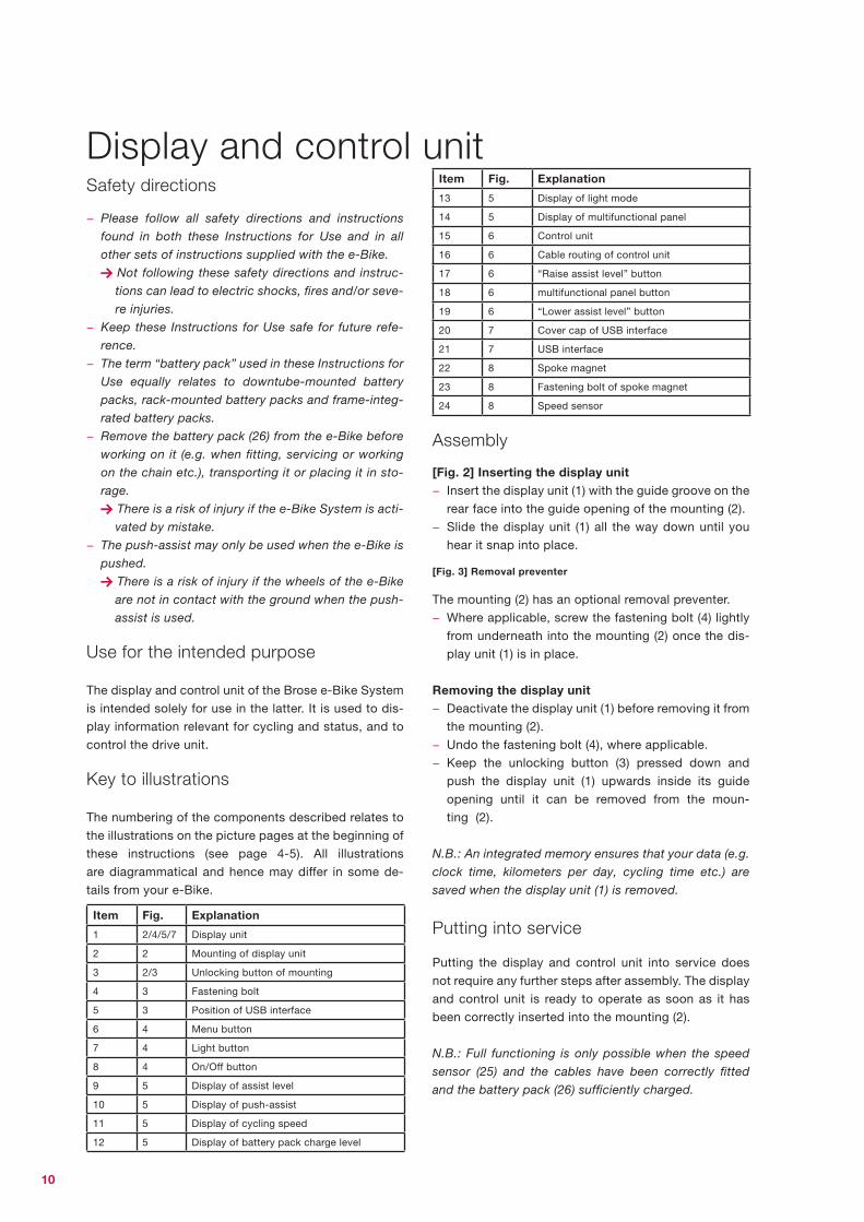
Use for the intended purpose
The display and control unit of the Brose e-Bike System
is intended solely for use in the latter. It is used to dis-
play information relevant for cycling and status, and to
control the drive unit.
Key to illustrations
The numbering of the components described relates to
the illustrations on the picture pages at the beginning of
these instructions (see page 4-5). All illustrations
are diagrammatical and hence may differ in some de-
tails from your e-Bike.
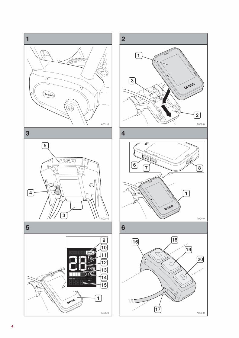
Item Fig. Explanation
1 2/4/5/7 Display unit
2 2 Mounting of display unit
3 2/3 Unlocking button of mounting
4 3 Fastening bolt
5 3 Position of USB interface
6 4 Menu button
7 4 Light button
8 4 On/Off button
9 5 Display of assist level
10 5 Display of push-assist
11 5 Display of cycling speed
12 5 Display of battery pack charge level
Item Fig. Explanation
13 5 Display of light mode
14 5 Display of multifunctional panel
15 6 Control unit
16 6 Cable routing of control unit
17 6 “Raise assist level” button
18 6 multifunctional panel button
19 6 “Lower assist level” button
20 7 Cover cap of USB interface
21 7 USB interface
22 8 Spoke magnet
23 8 Fastening bolt of spoke magnet
24 8 Speed sensor
Assembly
[Fig. 2] Inserting the display unit − Insert the display unit (1) with the guide groove on the
rear face into the guide opening of the mounting (2).
− Slide the display unit (1) all the way down until you
hear it snap into place.
[Fig. 3] Removal preventer
The mounting (2) has an optional removal preventer.
− Where applicable, screw the fastening bolt (4) lightly
from underneath into the mounting (2) once the dis-
play unit (1) is in place.
Removing the display unit − Deactivate the display unit (1) before removing it from
the mounting (2).
− Undo the fastening bolt (4), where applicable.
− Keep the unlocking button (3) pressed down and
push the display unit (1) upwards inside its guide
opening until it can be removed from the moun-
ting (2).
N.B.: An integrated memory ensures that your data (e.g.
clock time, kilometers per day, cycling time etc.) are
saved when the display unit (1) is removed.
Putting into service
Putting the display and control unit into service does
not require any further steps after assembly. The display
and control unit is ready to operate as soon as it has
been correctly inserted into the mounting (2).
N.B.: Full functioning is only possible when the speed
sensor (25) and the cables have been correctly fitted
and the battery pack (26) sufficiently charged.
Display and control unit

11
Operation
Once the display unit (1) is in place inside the moun-
ting (2), a battery pack (26) with sufficient charge has
been inserted into the e-Bike and the e-Bike System
has been switched on, the display unit (1) is supplied
with power by the battery pack (26).
N.B.: The display unit (1) does not have its own battery
and so cannot be used or operated outside of its moun-
ting (2).
N.B.: As soon as the battery pack (26) is in “Active
Mode”, the display unit (1) always remains switched on
during cycling, even if the motor assist has been deacti-
vated.
Switching on the Brose e-Bike System − Press the LED button (28) on the battery pack (26).
→ The display unit (1) activates automatically.
→ The e-Bike is now ready to use.
N.B.: Directly after switch-on, the software version num-
ber of the display unit (1) briefly appears in the multi-
functional panel (15).
Switching off the Brose e-Bike System
Standby mode
If the e-Bike is not moving, the display unit (1) and the
drive unit switch to a standby mode. This can however
also be activated manually.
If you want to park your e-Bike only for a short period,
this is how you switch to the standby mode:
− Press the On/Off button (8) briefly (< 2 seconds).
→ This switches off the display unit (1) and the drive
unit.
→ The battery pack (26) remains in the “Active Mode”
for two hours (see „Operating modes of battery
pack“ on page 16).
− As soon as you move your e-Bike again, the display
and the drive unit are re-activated and the Brose e-
Bike System is ready to use again.
− After 2 hours in the “Active Mode”, the battery
pack (26) goes into the “Deep Sleep Mode” (see
„Operating modes of battery pack“ on page 16).
Complete switch-off
There are two ways to switch off the Brose e-Bike Sys-
tem completely:
− Press the On/Off button (8) for a long time (< 2 se-
conds).
OR
− Press the LED button (28) on the battery pack (26) for
a long time (< 3 seconds).
→ This display unit (1), the drive unit and the battery
pack (26) are completely switched off.
N.B.: For reactivation after complete switch-off, the
system must be restarted using the LED button (28) on
the battery pack (26) (see „Switching battery pack on
and off“ on page 16).
[Fig. 5] Displays and settings
The display unit (1) shows various useful information:
− selected assist level (9)
− activity of push-assist (11)
− current cycling speed (12)
− current charge level of battery pack (13) in 10-per-
cent increments
− light mode (14)
− multifunctional panel (15)
Background lighting
The background lighting is activated for 2 seconds
whenever a button is pressed. The brightness here is
100 %.
At night, the background lighting is active all the time.
The brightness is much lower here so that the cyclist is
not dazzled. Brightness is regulated depending on the
ambient light.
Battery charge and remaining range
The charge level (13) of the battery pack is shown in the
display of the display unit (1) with 10 segments. One
segment here corresponds to about 10 % of the battery
capacity (see „Charge level display“ on page 15).
Display change in multifunctional panel (15)
− Press the menu button (6) on the display unit to
switch between the functions of the multifunctional
panel (15).

12
The multifunctional panel (15) presents the following
information:
→ Clock time
→ Trip distance
→ Trip calories
→ Trip time
→ Trip average speed
→ Total kilometers
→ Total time
→ Pedal resistance
Changing over the measurement units
− Switch off the display unit (1) using the On/Off but-
ton (8) (press it briefly for < 2 s).
− Press the On/Off button (8) and the menu button (6)
simultaneously for > 3 s until the software version of
the display unit (1) appears in the multifunctional pa-
nel (15).
→ All displayed units are changed over between “km”
and “mi” and “km/h” and “mph” respectively.
Setting the clock time
− In the multifunctional panel (15), change to the dis-
play of the clock time by pressing the menu but-
ton (6).
− Press the menu button (6) for > 2 s.
→ The hour display flashes.
− Set the hour display using the buttons “Raise assist
level” (18) and “Lower assist level” (20).
− Confirm your entry using the menu button (6) or the
multifunctional panel button (19).
→ The minute display flashes.
− Set the minute display using the buttons “Raise as-
sist level” (18) and “Lower assist level” (20).
− Confirm your entry and leave the menu using the
menu button (6) or the multifunctional panel but-
ton (19).
Reset trip functions
To reset the displayed values of the trip functions in the
multifunctional panel (15), proceed as follows:
− Select any trip function by pressing the menu but-
ton (6).
− Press the menu button (6) for > 2 seconds.
→ All displayed values of the trip functions are reset
to 0.
Reset total time
To reset the displayed value of the “Total time” function
in the multifunctional panel (15), proceed as follows:
− Select the “Total time” function by pressing the menu
button (6).
− Press the menu button (6) for > 2 seconds.
→ The displayed value of the “Total time“ function is
reset to 0.
Basic functions
Your Brose e-Bike System has three assist levels (9).
Their characteristics are set out in the following table:
Description
OffNo motor assist. At the same time, cycling without any
resistance.
CruiseCyclist dominates, with perceptible assistance by the
motor.
TourMotor enhances the strength of the cyclist over-pro-
portionally (and yet sustainably).
SportFull delivery of the motor force with little effort by the
cyclist.
Setting the assist level
− Press the button “Raise assist level” (18) on the con-
trol unit (16) to increase the assist level from OFF to
SPORT.
− Press the button “Lower assist level” (20) on the con-
trol unit (16) to reduce the assist level from SPORT to
OFF.
N.B.: If the control unit (16) on your e-Bike has been in-
stalled reversed by 180°, then the button functions of
items 18 and 20 are reversed. It is always the button
with the arrow pointing in the cycling direction that rai-
ses the assist level.
Activating/deactivating the push-assist
The push-assist (11) is used for assistance when
pushing the e-Bike. It is activated as follows:
− Switch the assist level to “OFF” to activate the push-
assist (11).
→ The arrow (10) is activated in the display of the
display unit (1) and signals that the push-assist (11)
is ready to operate.
− Press the button “Lower assist level” (20) down for >
1 second to activate the push-assist (11).
→ This activates the symbol for the push-assist (11)
in the display unit (1).
→ The e-Bike accelerates without pedal assist to a
manufacturer-specified speed of between 3 and 6
km/h
− Release the button “Lower assist level” (20) to deac-
tivate the push-assist (11).
Expanded functions
Light mode (14)
You can switch the lighting on or off manually, or select
the Automatic mode that automatically activates and
deactivates the lighting depending on the ambient
brightness.
− Press the light button (7) to switch the light on or off.
− Press the light button (7) for > 2 seconds to switch
the Automatic mode on or off.

13
→ An “A” inside the light symbol (14) comes on or
goes out.
[Fig. 7] Power supply via USB interface
External devices can be supplied with power and char-
ged using the Type A USB interface (22) integrated into
the mounting (2).
− Insert the display unit (1) into the mounting (2).
− Open the cover cap (21) of the USB interface (22).
− Use a suitable USB cable to make the connection
between the USB interface (22) and the required end
device.
→ If the connection is successful, the display
“CHArG” briefl y appears in the display unit (1).
Maintenance & cleaning
Keep all the components of your e-Bike clean, in parti-
cular the contacts of the battery pack (26) and its moun-
ting (31). Clean them carefully with a soft and dry cloth.
All components including the drive unit must not be
dipped in water or cleaned using a high-pressure clea-
ner.
For servicing or repairs to the e-Bike, please contact an
authorized bicycle dealer.
Disposal
The drive unit, display and control unit, battery pack (26),
speed sensor (25), accessories and packaging should
be recycled in environment-friendly processes. Do not
dispose of e-Bikes and their components as normal
waste!
For EU countries only:
In line with the European Union directive
2012/19/EU, electrical appliances which are
no longer serviceable must be collected se-
parately and recycled in environment-
friendly processes, and in line with directive 2006/66/
EC the same applies for defective or used-up batteries.
Please hand in battery packs (26) and display units (1)
which are no longer serviceable to an authorized bicyc-
le dealer.
Specifi cations
Display and control unit
Brose Material No. Display unit C54764
Brose Material No. Control unit C54760
Dimensions of display unit 44,0 x 62,5 x 8,0 mm
Dimensions of display area 38,0 x 50,0 mm
Dimensions of control unit 18,0 x 46,0 x 19,75 mm
Weight of display unit 67 g
Tightness IP65
Working temperature range -10 to 60°C
Storage temperature range -20 to 85°C
USB charge voltage 5 V "
USB charge current max. 500 mA
Lights
Rated voltage 6 V "
Rated output*
− Front light
− Rear light
2,6 W
0,6 W
* The rated power of the lights can differ depending on
the battery pack model used. Detailed information can
be obtained from the bicycle manufacturer and your
bicycle dealer.

14
Safety directions
− Please follow all safety directions and instructions
found in both these Instructions for Use and in all
other sets of instructions supplied with the e-Bike.
→ Not following these safety directions and instruc-
tions can lead to electric shocks, fires and/or seve-
re injuries. Injury and/or damage are also possible
as a result of dangerous reactions of chemical
substances leaking out of the battery pack (26) due
to a failure to follow the safety directions.
− Keep these Instructions for Use safe for future refe-
rence.
− The term “battery pack” used in these Instructions for
Use equally relates to downtube-mounted battery
packs, rack-mounted battery packs and frame-integ-
rated battery packs.
− Remove the battery pack (26) from the e-bike before
working on the latter (e.g. when fitting, servicing or
working on the chain etc.), transporting it, placing it in
storage or not using it for a lengthy period.
→ There is a risk of injury if the e-Bike System is acti-
vated by mistake.
− Do not open, take apart or break up the battery
pack (26).
→ There is a risk of a short-circuit. If the battery
pack (26) is opened, this invalidates all warranty
claims.
− Protect the battery pack (26) from heat (e.g. also from
continual sunlight), fire and immersion in water.
→ This creates an explosion risk.
− Keep all metal objects (e.g. paper clips, nails, screws,
keys etc.) well clear of the stored battery pack (26):
they could cause bridging of the contacts.
→ A short-circuit can lead to burns or fires. If short-
circuit damage results in this context, any claim for
warranty by Brose is invalidated.
− Fluid can leak out of the battery pack (26) if the latter
is not used correctly. Avoid any contact with this flu-
id. If contact does occur, rinse off the affected parts
of the body with water. If the fluid contacts any sensi-
tive membranes (e.g. eye), please also consult a
doctor without delay.
→ Leaking battery fluid can cause skin irritation or
burns.
− Battery packs (26) must not be subjected to any me-
chanical impacts.
→ There is a risk of the battery pack (26) being dama-
ged.
− On no account continue to use any battery packs (26)
which are defective or damaged.
→ There is an increased risk of short-circuits, fires or
electric shocks.
− If the battery pack (26) is damaged or used incorrect-
ly, vapors may be emitted. Let in plenty of fresh air,
and consult a doctor if you suffer from any complaint.
→ These vapors can irritate the airways.
− Charge the battery pack (26) using only the battery
charger (33) supplied with your Brose e-Bike System.
→ If other chargers are used, a risk of fire cannot be
ruled out.
− Use the battery pack (26) only in conjunction with e-
Bikes using the original Brose e-Bike System.
→ This is the only way to protect the battery pack (26)
from dangerous overloading.
− Only use battery packs (26) approved by the cycle
manufacturer for your e-Bike.
→ Using other battery packs can lead to injury and/or
fire risk. If other battery packs are used, Brose shall
not assume any liability or warranty.
− Please read and follow the safety directions and inst-
ructions found in both these instructions for use of all
components of the e-bike systems and the instruc-
tions for use of your e-bike.
− Keep the battery pack (26) away from children.
− Always keep the battery pack (26) clean and dry.
− Always ensure that the contacts of the battery
pack (26) are clean. If they are fouled, clean them with
a dry cloth.
− Avoid unnecessary charging. Do not charge the bat-
tery pack (26) over a long period if you do not use it.
− Never leave the battery pack (26) and battery char-
ger (33) unattended during charging.
Use for the intended purpose
The battery pack (26) is designed and intended only for
use in a Brose e-Bike System.
Key to illustrations
The numbering of the components described relates to
the illustrations on the picture pages at the beginning of
the instructions.
N.B.: All illustrations are diagrammatical and serve as
examples. They may differ in some details from your e-
Bike, since the Brose e-Bike System can be combined
with a large number of different battery pack variants.
Detailed information on the battery pack (26) used in
your e-Bike can be obtained from your bicycle dealer
and the cycle manufacturer.
Battery pack

15
Item Fig. Explanation
25 9/10 Battery pack
26 9 Charge level display
27 9 LED button
28 9 Integrated lock
29 9/11 Charging socket
30 10 Mounting rail
Assembly
[Fig. 10] Inserting/removing the battery pack
The Brose e-Bike System can be combined with a large
number of different battery pack variants. Fitting and
removal of the battery pack (26) depend on the battery
pack model used. Detailed information on this can be
obtained from your bicycle dealer and the bicycle ma-
nufacturer.
N.B.: Always switch off the battery pack (26) before in-
serting it into the mounting (31) or removing it from the
latter.
Locking/unlocking the battery pack key
The different assembly variants of the battery pack (26)
also entail different variants of the battery pack key (29).
Detailed information on locking/unlocking the battery
pack (26) can be obtained from your bicycle dealer and
the bicycle manufacturer.
Putting into service
Testing the battery pack before its first use
The battery pack (26) is supplied partially charged. For
that reason, test the battery pack (26) before charging it
for the first time or using it with your e-Bike.
− Press the LED button (28) to switch on the battery
pack (26).
→ The charge level display (27) should now light up
between “empty” and “full” and then display the
current charge level for about 4 seconds.
→ If no LED in the charge level display (27) comes on
and the battery pack (26) cannot be activated, it
may be that the cell voltage is too low and the
battery pack (26) needs to be charged.
→ If at least one but not all LEDs of the charge level
display (27) comes on, the battery pack (26) should
be fully charged before it is first used.
[Fig. 11] Charging the battery pack
Use only the battery charger (33) supplied with your e-
Bike. Only this charger is matched to the lithium-ion
battery pack (26) used in your e-Bike.
N.B.: The battery pack (26) is supplied partially charged
(approx. 30-50 %). To ensure full power from the battery
pack (26), fully charge it before its first use using the
battery charger (33) (see also „Battery charger“ on
page 18).
The battery pack (26) can be charged at any time, either
separately or on the e-Bike, without shortening its ser-
vice life.
− Connect the battery charger (33) to the mains.
→ The LED status display (34) of the battery char-
ger (33) should now be active (see „LED status
displays“ on page 19).
Battery pack not on e-Bike:
− Connect the charging plug (32) of the battery char-
ger (33) to the charging socket (30) of the battery
pack (26).
→ The charging operation begins.
N.B.: Some battery packs (26) can be provided with two
charging sockets (30). It is not important which of the
two sockets (30) you use for charging.
Battery pack on e-Bike:
− Connect the charging plug (32) of the battery char-
ger (33) to the vacant charging socket (30) of the
battery pack (26).
→ The charging operation begins.
N.B.: Interrupting the charging operation does not da-
mage the battery pack (26).
N.B.: If the battery pack (26) does not recharge, then the
cell voltage has fallen below the critical value of 2 V per
cell and the battery pack (26) is defective.
N.B.: Do not charge a damaged battery pack (26) and do
not use it. Please contact an authorized bicycle dealer.
N.B.: The battery pack (26) attains its maximum service
life when it is charged at ambient temperatures between
10 and 30 °C.
Charge level display
The five LEDs of the charge level display (27) show the
charge level of the battery pack (26) when the LED

16
button (28) is pressed. Each LED here corresponds to
about 20 % of capacity. When the battery pack (26) is
fully charged, all five LEDs light up. The charge level of
the switched-on battery pack (26) is also shown on the
display in the display unit (1) (see „Battery charge and
remaining range“ on page 11). If the capacity of the
battery pack (26) is below 10 %, the first LED of the
charge level display (27) flashes.
The battery pack (26) can be charged with and without
the display unit (1). Without the display unit (1), the
charging operation can only be tracked at the charge
level display (27) of the battery pack (26). The display
unit (1) can be removed during charging or fitted only
after the charging operation has started. The charge
level is indicated by the charge level display (27) on the
battery pack (26) and by the bar (13) on the display unit.
During charging, the LEDs of the charge level dis-
play (27) on the battery pack (26) light up. Each steady
LED corresponds to about 20 % of capacity. The flas-
hing LED shows the charging of the next 20 %.
During charging, the charge level display (27) is as fol-
lows:
LED steady LED flashing Charge level
- 1 0-19 %
1 2 20-39 %
1, 2 3 40-59 %
1, 2, 3 4 60-79 %
1, 2, 3, 4 5 80-99 %
1, 2, 3, 4, 5 - End of charging, battery
pack 100 % charged
Operation
Switching battery pack on and off
Switching on the battery pack (26) is one of the options
for switching on the Brose e-Bike System.
− Press the LED button (28) on the battery pack (26).
→ The LEDs of the charge level display (27) come on
briefly and then show the current charge level for
about 4 seconds.
N.B.: If the capacity of the battery pack (26) is below
10 %, only the first LED of the charge level display (27)
flashes.
− To switch off the battery pack (26), press the LED
button (28) for > 3 seconds.
→ The LEDs of the charge level display (27) go out.
→ The e-Bike System too is also switched off.
Operating modes of battery pack
Active Mode
After switch-on, the battery pack (26) is in the “Active
Mode”. It remains in the “Active Mode” for 2 hours wit-
hout any further action (operation or movement of the
e-Bike).
The “Active Mode” is activated by operating the LED
button (28), by charging the battery pack (26), or by in-
serting the battery pack (26) into the e-Bike.
Deep Sleep Mode
To minimize the power consumed by the system itself,
the battery pack (26) switches automatically to the
“Deep Sleep Mode” after 2 hours in the “Active Mode”
without any activity and with the display unit (1) swit-
ched off. The “Deep Sleep Mode” is also activated
when the LED button (28) or the On/Off button (8) of the
display unit (1) is pressed for > 3 seconds or when the
battery pack (26) is not inserted into the e-Bike for lon-
ger than 30 seconds.
Power reduction of battery pack
For self-protection against overloading or overheating,
the battery pack (26) has a function for automatic power
reduction depending on the charge level and tempera-
ture.
Above a cell temperature of 70°C, and between 0 and
10°C, the motor power is reduced in 4 stages (25 %
each) until the drive is switched off.
With a charge level of < 5 %, the drive assist is switched
off, so that the display unit (1) and the lights can be
operated for at least 4 more hours before the battery
pack (26) deactivates for self-protection.
Maintenance, cleaning and storage
Keep the battery pack (26) clean. Clean it carefully with
a soft and dry cloth. The battery pack (26) must not be
immersed in water or cleaned using a water jet. If the
battery pack (26) is no longer working, please contact
an authorized bicycle dealer. Set down the battery
pack (26) only on clean surfaces. Avoid in particular any
fouling of the charging sockets (30) and of the contacts.
The service life of the battery pack (26) can be extended
if it is looked after well and above all stored in the right
conditions:
Temperature 18-23°C
Humidity 0-80 %
Charge level 70 %

17
As the battery pack (26) gets older, its capacity will di-
minish even when it is looked after well. A considerably
shorter operating time after charging indicates that the
battery pack (26) is used up. You should then replace it.
Recharging the battery pack during storage
Check the charge level of the battery pack (26) after it
has been in storage for around 3 months, and recharge
it to about 60-79 % if necessary.
Transport
The battery pack (26) may only be dispatched in pa-
ckaging suitable for hazardous goods and provided
with the necessary warning notices.
If you have any questions about transport, please con-
tact an authorized bicycle dealer. The dealer can also
provide you with suitable transport packaging.
Disposal
The drive unit, display and control unit, battery pack (26),
speed sensor (25), accessories and packaging should
be recycled in environment-friendly processes. Do not
dispose of e-Bikes and their components as normal
waste!
For EU countries only:
In line with the European Union directive
2012/19/EU electrical appliances which are
no longer serviceable must be collected se-
parately and recycled in environment-
friendly processes, and in line with directive 2006/66/
EC the same applies for defective or used-up batteries.
Please hand in battery packs (26) and display units (1)
which are no longer serviceable to an authorized bicyc-
le dealer.
Specifi cations
You will fi nd detailed information on the specifi cations
of the battery pack (26) used in your e-Bike in the data
sheet supplied by the bicycle manufacturer.
Battery pack
Battery technology Lithium ions
Rated output voltage 36 V "
Cell confi guration 10S4P (40 cells) or
10S5P (50 cells)
Capacity Variable

18
Safety directions
− Please follow all safety directions and instructions
found in both these Instructions for Use and in all
other sets of instructions supplied with the e-Bike.
→ Not following these safety directions and instruc-
tions can lead to electric shocks, fires and/or seve-
re injuries.
− Keep these Instructions for Use safe for future refe-
rence.
− The term “battery pack“ used in these Instructions for
Use equally relates to downtube-mounted battery
packs, rack-mounted battery packs and frame-integ-
rated battery packs.
− Never expose the battery charger (33) to heavy mois-
ture (e.g. rain, snow etc.).
→ If water gets into the battery charger (33), there is
a risk of electric shock.
− Only charge the lithium-ion battery pack (26) supplied
for your Brose e-Bike System. Battery voltage and
charge voltage of the battery charger (33) must
match.
→ Otherwise there is a risk of fire and explosion.
− Always keep the battery charger (33) clean.
→ Fouling leads to a risk of electric shock.
− Check the battery charger (33), cables and plugs eve-
ry time before using them. If you discover any dama-
ge, on no account use the battery charger (33). Do
not open the battery charger (33), and have it repaired
only by qualified experts using only original spare
parts.
→ Damaged battery chargers (33), cables and plugs
increase the risk of an electric shock.
− Do not operate the battery charger (33) on easily in-
flammable surfaces (e.g. paper, textiles etc.) or in in-
flammable surroundings.
→ The heating up of the battery charger (33) during
charging creates a fire risk.
− Children and persons unable to safely operate the
battery charger (33) due to lower physical, sensory or
mental capacities or their inexperience or their lack of
knowledge, may not use the charger without supervi-
sion or instruction by a responsible adult.
→ Failing that, there is a risk of incorrect operation
and injury.
− Please read and follow the safety directions and inst-
ructions found in both the Instructions for Use of the
battery pack (26) and of the drive unit/display unit and
in the Instructions for Use of your e-Bike.
− The underside of the battery charger (33) is provided
with a brief version of important safety directions in
English, French and Spanish stating the following:
→ For safe use please follow the Instructions for Use.
Risk of electric shock.
→ Only use in dry surroundings.
→ Only charge battery packs (26) of the Brose e-Bike
System. Other battery packs (26) might explode
and cause injury.
→ Do not replace the mains cable. There is a risk of
fire and explosion.
− Never leave the battery pack (26) and battery char-
ger (33) unattended during charging.
Use for the intended purpose
The battery charger (33) must be used exclusively for
charging the battery pack (26) supplied with the Brose
e-Bike System.
Key to illustrations
The numbering of the components described relates to
the illustrations on the picture pages at the beginning of
the instructions.
N.B.: All illustrations are diagrammatical and serve as
examples. They may differ in some details from your e-
Bike, since the Brose e-Bike System can be combined
with various battery chargers (33). Detailed information
on the battery charger (33) supplied with your e-Bike
can be obtained from your bicycle dealer and the bicyc-
le manufacturer.
Item Fig. Explanation
31 11/12 Charge plug
32 12 Battery charger
33 12 LED status display
34 12 Mains connection plug
35 12 Mains connection
Putting into service
[Fig. 12] Connecting the battery charger to the mains
N.B.: Ensure the correct mains voltage! The voltage of
the power source must match the specifications on the
rating plate of the battery charger (33)
− Connect the mains connection plug (35) to the batte-
ry charger (33).
− Connect the battery charger (33) to the mains by
plugging the mains cable into a suitable socket.
→ The LED status display (34) of the battery char-
ger (33) should now be active.
→ The battery charger (33) is now ready to operate.
Battery charger

19
Operation
Charging the battery pack − Charge the battery pack (26) only when all safety di-
rections are followed.
Charging the removed battery pack
− Switch off the battery pack (26) (see „Switching bat-
tery pack on and off“ on page 16).
− Remove the battery pack (26) from the mounting (31)
on the e-Bike (see „[Fig. 10] Inserting/removing the
battery pack“ on page 15).
N.B.: Set down the battery pack (26) only on clean sur-
faces. Avoid in particular any fouling of the charging
sockets (30) and of the contacts.
− Insert the charging plug (32) of the battery char-
ger (33) into one of the two charging sockets (30) on
the battery pack (26).
→ The charging operation begins.
[Fig. 11] Charging the battery packs on the e-Bike
− Switch off the battery pack (26).
− Insert the charging plug (32) into the vacant charging
socket (30) on the battery pack (26).
→ The charging operation begins.
N.B.: Avoid any fouling of the charging sockets (30) and
of the contacts.
Charging in progress
Charging begins automatically as soon as the battery
charger (33) has been connected to the battery pack (26)
and the mains.
The battery pack (26) can be charged with and without
the display unit (1). Without the display unit (1), the
charging operation can only be tracked at the charge
level display (27) of the battery pack (26). The display
unit (1) can be removed during charging or fi tted only
after the charging operation has started. The charge
level is indicated by the charge level display (27) on the
battery pack (26) and by the bar (13) on the display
unit (1). During charging, the LEDs of the charge level
display (27) on the battery pack (26) come on (see
„Charge level display“ on page 15).
N.B.: Be careful when you touch the battery charger (33)
during charging. It can become very hot, particularly in
high ambient temperatures.
Once the battery pack (26) is fully charged, the LEDs go
out immediately. The charging operation is terminated.
− Disconnect the battery charger (33) from the mains.
− Disconnect the battery pack (26) from the battery
charger (33).
→ This switches off the battery pack (26) automati-
cally.
If the battery pack (26) is not disconnected from the
battery charger (33) after charging and the battery char-
ger (33) remains connected to the mains, it will switch
back on after a few hours, check the charge state of the
battery pack (26), and if necessary begin another char-
ging operation.
LED status displays
Battery charger 2 A
Standby green LED steady
Pre-charge green and red LEDs fl ashing
Charging in progress red LED steady
battery pack full / trickle charge green LED steady
Battery test green LED steady
Battery charger 4 A
Standby Green LED fl ashing
Charging in progress red LED steady
battery pack full / trickle charge green LED steady
Error green and red LEDs fl ashing
Maintenance & cleaning
If the battery charger (33) is no longer serviceable, ple-
ase contact an authorized bicycle dealer.
Use a soft and dry cloth to clean the battery charger. Do
not use water or any other cleaning fl uids!
Disposal
Battery chargers (33), accessories and packaging
should be recycled in environment-friendly processes.
Do not dispose of battery chargers (33) as normal was-
te!
For EU countries only:
In line with European Directive 2012/19/ EU
on waste electrical and electronic equip-
ment and its implementation in national law,
chargers which are no longer usable must
be collected separately and recycled in environment-
friendly processes.

20
Specifications
The Brose e-Bike System can be combined with a large
number of battery chargers (33). Detailed information on
your model can be obtained from your bicycle dealer
and the bicycle manufacturer.
Battery charger 2 A
Dimensions 140,0 x 70,0 x 40,0 mm
Weight 475 g
End-of-charge voltage 42 V "
Rated output current 2 A
Working temperature range -10 to 40°C
Storage temperature range -20 to 70°C
Battery charger 4 A
Dimensions 206,0 x 94,0 x 61,0 mm
Weight 770 g
End-of-charge voltage 42 V "
Rated output current 4 A
Working temperature range 0 to 45°C
Storage temperature range -25 to 70°C

21
If any problems occur during use of your Brose e-Bike System, first of all check them off against those listed in the
table. This will enable you to solve the problem yourself in many cases.
Symptom Possible cause Solution approach
Display unit (1) and/or Brose e-Bike System
cannot be activated.
Malfunction of battery pack (26) despite full
charge
Press the LED button (28) to check whether
the battery pack can be switched on. The
LEDs of the charge level display (27) on the
battery pack (26) should come on. If this is
not the case, there may be a defect in the
battery pack (26).
Battery pack (26) not correctly snapped into
mounting (31)
Remove the battery pack (26) again and
then re-insert it. Ensure that it is seated
correctly.
Battery pack (26) not charged Complete a charging operation using the
supplied battery charger (33).
Contacts of battery pack (26) and/or of moun-
ting (31) fouled
Check that all contacts are clean. If neces-
sary clean them with a soft and dry cloth.
Display unit (1) not correctly snapped into
mounting (2)
Remove the display unit (1) again and then
re-insert it. Ensure that it is seated correctly.
Contacts of display unit (1) and/or of moun-
ting (2) fouled
Check that all contacts are clean. If neces-
sary clean them with a soft and dry cloth.
Plug connections at the drive unit not correct-
ly inserted
Check the cables and plug connections,
and connect them properly where necessa-
ry.
Display unit (1) not supplying cycling data
even though the e-Bike is in motion.
Spoke magnet (23) not correctly fitted (dis-
tance from speed sensor (25))
Check the fitting of the spoke magnet (23),
particularly its distance from the speed
sensor (25) on the chain stay. This distance
must be between 5 and 17 mm (see Fig. 8).
Correct the distance where necessary.
Bike lights cannot be activated. Cable for lights incorrectly connected Check the cables and plug connections,
and connect them properly where necessa-
ry.
Display unit (1) displays an error code in the
multifunctional panel (15).
There is an active error in the system. Please refer to the following table
Error codes
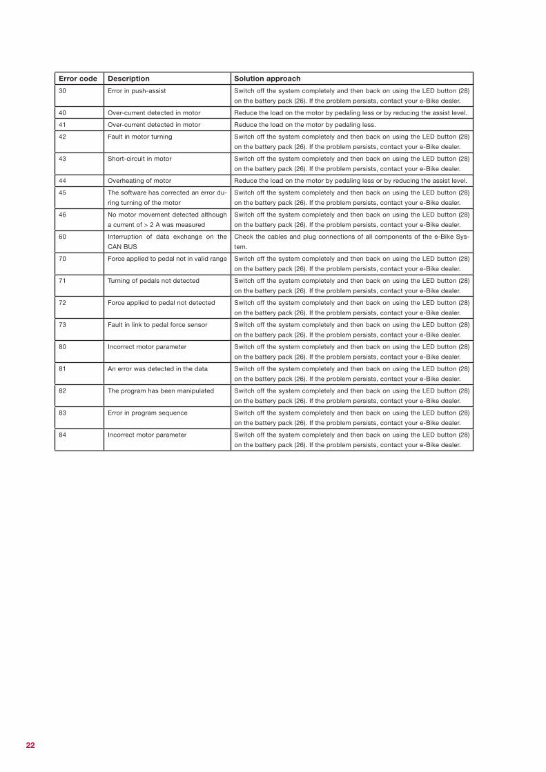
You can see from the following table which error is present in the system and what can be done when your display
unit (1) displays an error code.
Error code Description Solution approach
10 The battery voltage is too low. Charge the battery pack (26) using the battery charger (33).
11 The battery voltage is too high. Switch off the system completely and then back on using the LED button (28)
on the battery pack (26). If the problem persists, contact your e-Bike dealer.
12 The battery is almost/completely dis-
charged
Charge the battery pack (26) using the battery charger (33).
20 Electrical measurements are faulty. Switch off the system completely and then back on using the LED button (28)
on the battery pack (26). If the problem persists, contact your e-Bike dealer.
21 Thermo sensor defective Switch off the system completely and then back on using the LED button (28)
on the battery pack (26). If the problem persists, contact your e-Bike dealer.
23 Thermo sensor defective Switch off the system completely and then back on using the LED button (28)
on the battery pack (26). If the problem persists, contact your e-Bike dealer.
24 The internal voltage is outside the wor-
king range.
Charge the battery pack (26) using the battery charger (33).
25 Error in motor current measurement Switch off the system completely and then back on using the LED button (28)
on the battery pack (26). If the problem persists, contact your e-Bike dealer.
26 A software reset has been performed Switch off the system completely and then back on using the LED button (28)
on the battery pack (26). If the problem persists, contact your e-Bike dealer.
Troubleshooting
22
Error code Description Solution approach
30 Error in push-assist Switch off the system completely and then back on using the LED button (28)
on the battery pack (26). If the problem persists, contact your e-Bike dealer.
40 Over-current detected in motor Reduce the load on the motor by pedaling less or by reducing the assist level.
41 Over-current detected in motor Reduce the load on the motor by pedaling less.
42 Fault in motor turning Switch off the system completely and then back on using the LED button (28)
on the battery pack (26). If the problem persists, contact your e-Bike dealer.
43 Short-circuit in motor Switch off the system completely and then back on using the LED button (28)
on the battery pack (26). If the problem persists, contact your e-Bike dealer.
44 Overheating of motor Reduce the load on the motor by pedaling less or by reducing the assist level.
45 The software has corrected an error du-
ring turning of the motor
Switch off the system completely and then back on using the LED button (28)
on the battery pack (26). If the problem persists, contact your e-Bike dealer.
46 No motor movement detected although
a current of > 2 A was measured
Switch off the system completely and then back on using the LED button (28)
on the battery pack (26). If the problem persists, contact your e-Bike dealer.
60 Interruption of data exchange on the
CAN BUS
Check the cables and plug connections of all components of the e-Bike Sys-
tem.
70 Force applied to pedal not in valid range Switch off the system completely and then back on using the LED button (28)
on the battery pack (26). If the problem persists, contact your e-Bike dealer.
71 Turning of pedals not detected Switch off the system completely and then back on using the LED button (28)
on the battery pack (26). If the problem persists, contact your e-Bike dealer.
72 Force applied to pedal not detected Switch off the system completely and then back on using the LED button (28)
on the battery pack (26). If the problem persists, contact your e-Bike dealer.
73 Fault in link to pedal force sensor Switch off the system completely and then back on using the LED button (28)
on the battery pack (26). If the problem persists, contact your e-Bike dealer.
80 Incorrect motor parameter Switch off the system completely and then back on using the LED button (28)
on the battery pack (26). If the problem persists, contact your e-Bike dealer.
81 An error was detected in the data Switch off the system completely and then back on using the LED button (28)
on the battery pack (26). If the problem persists, contact your e-Bike dealer.
82 The program has been manipulated Switch off the system completely and then back on using the LED button (28)
on the battery pack (26). If the problem persists, contact your e-Bike dealer.
83 Error in program sequence Switch off the system completely and then back on using the LED button (28)
on the battery pack (26). If the problem persists, contact your e-Bike dealer.
84 Incorrect motor parameter Switch off the system completely and then back on using the LED button (28)
on the battery pack (26). If the problem persists, contact your e-Bike dealer.

23
Your notes

Brose Antriebstechnik GmbH & Co. KG, BerlinSickingenstr. 29-3810553 Berlin+49 30 343498 100+49 30 343498 [email protected]