Embed Size (px)
Citation preview
The Bose® Acoustimass® 15 Home Theater SpeakerSystem
Owner’s GuideOctober 22, 2001
AM194452_06_V.pdf
2 October 22, 2001 AM194452_06_V.pdf
Introduction
Thank youWe appreciate your choice of the Bose® Acoustimass® 15 home theater speaker system. Withthese Virtually Invisible® speakers you will surround yourself with realistic sound, with aminimal amount of equipment. Your system features new third generation Acoustimass cubespeaker arrays, a product of the continuous research and development at Bose Corporation.These cube speakers deliver more lifelike sound and better overall performance, yet aresmaller than their predecessors.
Your speaker system is completely compatible with the most modern home theater receiversand program material. Bose proprietary Integrated Signal Processing and dedicated bassamplification assure hi-fidelity and bass for all channels regardless of your home theaterreceiver’s settings.
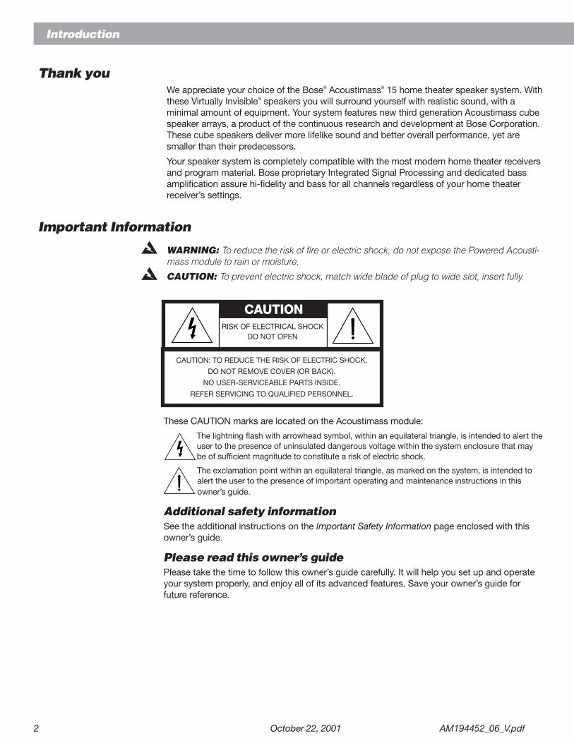
Important Information
WARNING: To reduce the risk of fire or electric shock, do not expose the Powered Acousti-mass module to rain or moisture.
CAUTION: To prevent electric shock, match wide blade of plug to wide slot, insert fully.
CAUTION: TO REDUCE THE RISK OF ELECTRIC SHOCK,
DO NOT REMOVE COVER (OR BACK).
NO USER-SERVICEABLE PARTS INSIDE.
REFER SERVICING TO QUALIFIED PERSONNEL.
CAUTIONRISK OF ELECTRICAL SHOCK
DO NOT OPEN
These CAUTION marks are located on the Acoustimass module:
The lightning flash with arrowhead symbol, within an equilateral triangle, is intended to alert theuser to the presence of uninsulated dangerous voltage within the system enclosure that maybe of sufficient magnitude to constitute a risk of electric shock.
The exclamation point within an equilateral triangle, as marked on the system, is intended toalert the user to the presence of important operating and maintenance instructions in thisowner’s guide.
Additional safety informationSee the additional instructions on the Important Safety Information page enclosed with thisowner’s guide.
Please read this owner’s guidePlease take the time to follow this owner’s guide carefully. It will help you set up and operateyour system properly, and enjoy all of its advanced features. Save your owner’s guide forfuture reference.
AM251174_03_V.pdf October 22, 2001 a
Important Safety Instructions
1. Read these instructions – for all componentsbefore using this product.
2. Keep these instructions – for future reference.3. Heed all warnings – on the product and in the
owner’s guide.4. Follow all instructions.5. Do not use this apparatus near water or
moisture – Do not use this product near abathtub, washbowl, kitchen sink, laundry tub, in awet basement, near a swimming pool, or any-where else that water or moisture are present.
6. Clean only with a dry cloth – and as directedby Bose® Corporation. Unplug this product fromthe wall outlet before cleaning.
7. Do not block any ventilation openings.Install in accordance with themanufacturer’s instructions – To ensurereliable operation of the product and to protect itfrom overheating, put the product in a positionand location that will not interfere with its properventilation. For example, do not place the producton a bed, sofa, or similar surface that may blockthe ventilation openings. Do not put it in a built-insystem, such as a bookcase or a cabinet that maykeep air from flowing through its ventilationopenings.
8. Do not install near any heat sources, suchas radiators, heat registers, stoves or otherapparatus (including amplifiers) that pro-duce heat.
9. Do not defeat the safety purpose of thepolarized or grounding-type plug. A polar-ized plug has two blades with one widerthan the other. A grounding-type plug hastwo blades and a third grounding prong. Thewider blade or third prong are provided foryour safety. If the provided plug does not fitin your outlet, consult an electrician forreplacement of the obsolete outlet.
10. Protect the power cord from being walkedon or pinched, particularly at plugs, conve-nience receptacles, and the point wherethey exit from the apparatus.
11. Only use attachments/accessories speci-fied by the manufacturer.
12. Use only with the cart, stand, tripod,bracket or table specified by themanufacturer or sold with theapparatus. When a cart is used,use caution when moving thecart/apparatus combination toavoid injury from tip-over.
13. Unplug this apparatus during lightningstorms or when unused for long periods oftime – to prevent damage to this product.
14. Refer all servicing to qualified service person-nel. Servicing is required when the apparatushas been damaged in any way: such as power-supply cord or plug is damaged; liquid hasbeen spilled or objects have fallen into theapparatus; the apparatus has been exposed torain or moisture, does not operate normally, orhas been dropped – Do not attempt to service thisproduct yourself. Opening or removing covers mayexpose you to dangerous voltages or other hazards.Please call Bose to be referred to an authorizedservice center near you.
15. To prevent risk of fire or electric shock, avoidoverloading wall outlets, extension cords, orintegral convenience receptacles.
16. Do not let objects or liquids enter the product –as they may touch dangerous voltage points orshort-out parts that could result in a fire or electricshock.
17. See product enclosure for safety relatedmarkings.
Information about products thatgenerate electrical noise
If applicable, this equipment has been tested and foundto comply with the limits for a Class B digital device,pursuant to Part 15 of the FCC rules. These limits aredesigned to provide reasonable protection againstharmful interference in a residential installation. Thisequipment generates, uses, and can radiate radiofrequency energy and, if not installed and used in accor-dance with the instructions, may cause harmful interfer-ence to radio communications. However, this is noguarantee that interference will not occur in a particularinstallation. If this equipment does cause harmful interfer-ence to radio or television reception, which can bedetermined by turning the equipment off and on, you areencouraged to try to correct the interference by one ormore of the following measures:
• Reorient or relocate the receiving antenna.
• Increase the separation between the equipment andreceiver.
• Connect the equipment to an outlet on a differentcircuit than the one to which the receiver is connected.
• Consult the dealer or an experienced radio/TV techni-cian for help.
Note: Unauthorized modification of the receiver or radioremote control could void the user’s authority to operatethis equipment.This product complies with the Canadian ICES-003 ClassB specifications.
En
gli
sh
b October 22, 2001 AM251174_03_V.pdf
Important Safety Instructions
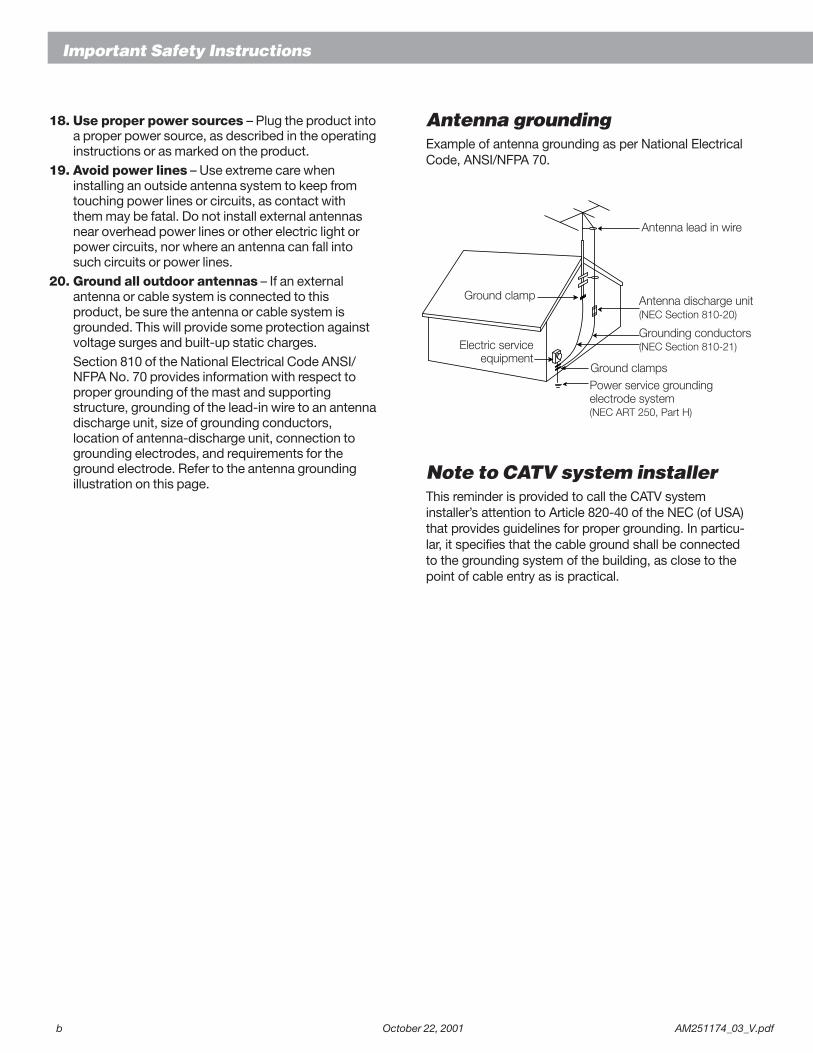
Antenna groundingExample of antenna grounding as per National ElectricalCode, ANSI/NFPA 70.
Note to CATV system installerThis reminder is provided to call the CATV systeminstaller’s attention to Article 820-40 of the NEC (of USA)that provides guidelines for proper grounding. In particu-lar, it specifies that the cable ground shall be connectedto the grounding system of the building, as close to thepoint of cable entry as is practical.
18. Use proper power sources – Plug the product intoa proper power source, as described in the operatinginstructions or as marked on the product.
19. Avoid power lines – Use extreme care wheninstalling an outside antenna system to keep fromtouching power lines or circuits, as contact withthem may be fatal. Do not install external antennasnear overhead power lines or other electric light orpower circuits, nor where an antenna can fall intosuch circuits or power lines.
20. Ground all outdoor antennas – If an externalantenna or cable system is connected to thisproduct, be sure the antenna or cable system isgrounded. This will provide some protection againstvoltage surges and built-up static charges.Section 810 of the National Electrical Code ANSI/NFPA No. 70 provides information with respect toproper grounding of the mast and supportingstructure, grounding of the lead-in wire to an antennadischarge unit, size of grounding conductors,location of antenna-discharge unit, connection togrounding electrodes, and requirements for theground electrode. Refer to the antenna groundingillustration on this page.
Antenna lead in wire
Antenna discharge unit(NEC Section 810-20)
Grounding conductors(NEC Section 810-21)
Power service groundingelectrode system(NEC ART 250, Part H)
Ground clamps
Ground clamp
Electric serviceequipment
AM194452_06_V.pdf October 22, 2001 3
Contents
Where to find...Introduction
Thank you ..................................................................................................................... 2Important Information ................................................................................................... 2
ContentsWhere to find ................................................................................................................ 3For your records ........................................................................................................... 3
Setting UpBefore you begin ........................................................................................................... 4Unpack the carton ........................................................................................................ 4Placing your speakers to achieve realistic home theater sound .................................. 5
Center cube speaker ........................................................................................... 5Left and right front cube speakers ...................................................................... 6Surround cube speakers ..................................................................................... 6Powered Acoustimass® module .......................................................................... 6
Connect the speakers ................................................................................................... 7Connect the Powered Acoustimass module to the center
and front cube arrays ................................................................................... 7Connect the Powered Acoustimass module to the surround cube arrays ......... 8Connect the Powered Acoustimass module to the receiver ............................... 8
Check the connections ................................................................................................. 9Plug in the Powered Acoustimass Module ......................................................... 9
Using Your Acoustimass 15 speakersFor realistic home theater sound ................................................................................ 10
LFE level control ................................................................................................ 10Bass control ...................................................................................................... 10Setting your Dolby Pro-Logic receiver .............................................................. 10Setting your Dolby Digital receiver .................................................................... 10Be sure to get the Dolby Digital signal .............................................................. 11
Maintaining Your Acoustimass 15 speakersTroubleshooting .......................................................................................................... 12Customer service ........................................................................................................ 12Cleaning the speakers ................................................................................................ 12
Product InformationTechnical information.................................................................................................. 13Warranty period .......................................................................................................... 13Accessories................................................................................................................. 13
Bose® Corporation .................................................................................... inside back cover
For your recordsSerial numbers are located on the connection panel of the Powered Acoustimass module.
Serial number: _________________________________________________________________
Dealer name: __________________________________________________________________
Dealer phone: _______________________ Purchase date: ___________________________
We suggest you keep your sales slip and warranty card together with this owner’s guide.
Esp
añ
ol
Fra
nç
ais
4 October 22, 2001 AM194452_06_V.pdf
Before you beginBose® Virtually Invisible® speaker technology allows you to enjoy lifelike home performancesfrom the very latest surround-sound encoded movies, CDs, and television shows, without aroom full of speakers. Each of the five cube speaker arrays, along with the Powered Acousti-mass® module, reproduces the full-spectrum of sound from multi-channel digital program-ming. Integrated Signal Processing assures full bass performance from all channels, at alllistening levels, regardless of your receiver settings.
Your stereo VCR, stereo television, or DVD player sends the encoded program material to thesurround-sound receiver, which interprets and distributes the information to the PoweredAcoustimass module. The module delivers the bass for all channels and sends appropriatesounds to each cube array. The sound mix varies with different program types: dialogue isusually sent to the center speaker, a visual soundstage is created by the left and right frontspeakers, and you feel in the center of the action because sounds and special effects aredirected to the surround (rear) speakers. At any point in a surround-sound performance, youmay hear sound from one, a few, or all of the speakers.
To select surround-encoded program material, look for any of the terms Surround, DolbySurround, the double-D symbol *, other digital formats, or the word “sur-round” preceding a TV broadcast. Your system is fully compatible with the latest hometheater receivers. You can also enjoy a wide variety of stereo programming that is not sur-round-encoded with your Acoustimass 15 speakers.
Unpack the carton• Remove any staples from the opened carton flaps.
• Remove the brown inner carton containing the five cube speaker arrays.
• Gently roll the carton over onto its side and then onto its opening.
• Slowly lift the carton from around the Powered Acoustimass module’s packing cushions.
• Do not detach the removable cables connected to the Powered Acoustimass module.
• If the speakers or the module appear damaged, do not use them. Repack everything inthe original carton and contact your authorized Bose dealer immediately.
Note: Now is a good time to record the serial number of these speakers on page 2 of thisguide and on your warranty card. Please save all packing materials for possible future use.
WARNING: The Powered Acoustimass module weighs 33 pounds (15 kg). Use good liftingpractice to avoid injury.
WARNING: To avoid danger of suffocation, keep the plastic bags that wrap these speakersout of the reach of children.
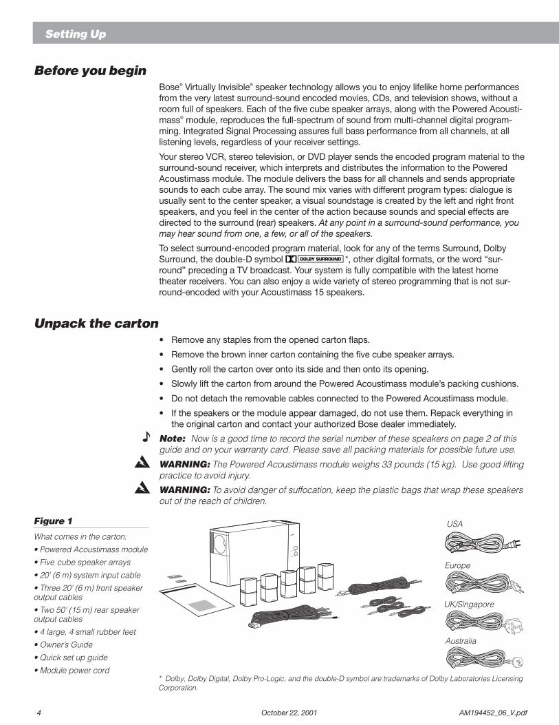
Figure 1
What comes in the carton:
• Powered Acoustimass module
• Five cube speaker arrays
• 20' (6 m) system input cable
• Three 20' (6 m) front speakeroutput cables
• Two 50' (15 m) rear speakeroutput cables
• 4 large, 4 small rubber feet
• Owner’s Guide
• Quick set up guide
• Module power cord
Setting Up
* Dolby, Dolby Digital, Dolby Pro-Logic, and the double-D symbol are trademarks of Dolby Laboratories LicensingCorporation.
Europe
Australia
UK/Singapore
USA
AM194452_06_V.pdf October 22, 2001 5
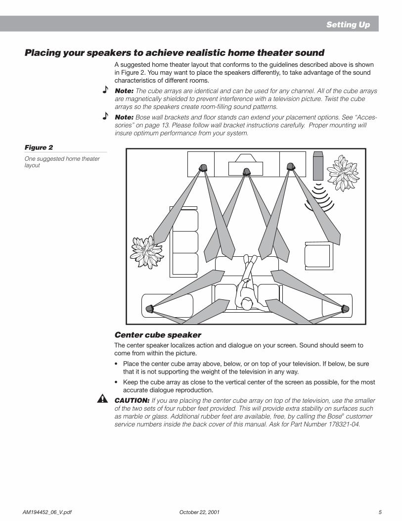
Placing your speakers to achieve realistic home theater soundA suggested home theater layout that conforms to the guidelines described above is shownin Figure 2. You may want to place the speakers differently, to take advantage of the soundcharacteristics of different rooms.
Note: The cube arrays are identical and can be used for any channel. All of the cube arraysare magnetically shielded to prevent interference with a television picture. Twist the cubearrays so the speakers create room-filling sound patterns.
Note: Bose wall brackets and floor stands can extend your placement options. See “Acces-sories” on page 13. Please follow wall bracket instructions carefully. Proper mounting willinsure optimum performance from your system.
Figure 2
One suggested home theaterlayout
Setting Up
Center cube speakerThe center speaker localizes action and dialogue on your screen. Sound should seem tocome from within the picture.
• Place the center cube array above, below, or on top of your television. If below, be surethat it is not supporting the weight of the television in any way.
• Keep the cube array as close to the vertical center of the screen as possible, for the mostaccurate dialogue reproduction.
CAUTION: If you are placing the center cube array on top of the television, use the smallerof the two sets of four rubber feet provided. This will provide extra stability on surfaces suchas marble or glass. Additional rubber feet are available, free, by calling the Bose® customerservice numbers inside the back cover of this manual. Ask for Part Number 178321-04.
6 October 22, 2001 AM194452_06_V.pdf
Setting Up
Left and right front cube speakersThe left and right front speakers create a sound image wider than the screen that seemsnatural to viewers sitting anywhere in the room. You can place them near a TV screen with nopicture interference. See figure 2.
• Place the front cube arrays on either side of your TV, at least 6 feet (2 m), or as much as15 feet (5 m) apart.
Surround cube speakersThe surround, or rear, speakers add discrete sounds and special effects that expand thevisual image, bringing the viewer into the center of the action. The surround speakers maycarry dialog as well. The surround speakers should be positioned to allow the sound to reachthe viewer from both sides, rather than from directly behind. See Figure 2.
• Place the speakers at ear height or higher, if possible
• Adjust the rear surround speakers to direct the sound to the front and back of the listener.
Powered Acoustimass® moduleBose® Acoustimass speaker technology takes advantage of the fact that the source of purebass sound is difficult to locate, so you can hide the Powered Acoustimass module conve-niently out of sight. Place the module at the same end of the room as the television monitor.
• You may hide the module behind or under furniture, but do not block the opening. Be surethere is at least 2 inches (5 cm) between the opening and any surface.
• If the opening faces the wall it increases the bass; if it faces away it decreases the bass.For the most bass response, place the opening 2 to 3 inches (5 to 8 cm) from a wall orcorner.
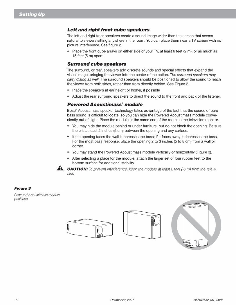
• You may stand the Powered Acoustimass module vertically or horizontally (Figure 3).
• After selecting a place for the module, attach the larger set of four rubber feet to thebottom surface for additional stability.
CAUTION: To prevent interference, keep the module at least 2 feet (.6 m) from the televi-sion.
Figure 3
Powered Acoustimass modulepositions
AM194452_06_V.pdf October 22, 2001 7
Setting Up
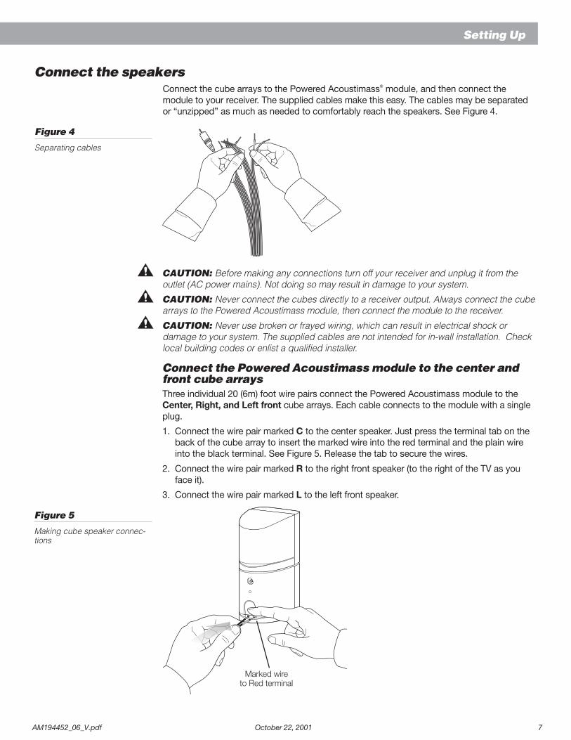
Connect the speakersConnect the cube arrays to the Powered Acoustimass® module, and then connect themodule to your receiver. The supplied cables make this easy. The cables may be separatedor “unzipped” as much as needed to comfortably reach the speakers. See Figure 4.
Figure 4
Separating cables
CAUTION: Before making any connections turn off your receiver and unplug it from theoutlet (AC power mains). Not doing so may result in damage to your system.
CAUTION: Never connect the cubes directly to a receiver output. Always connect the cubearrays to the Powered Acoustimass module, then connect the module to the receiver.
CAUTION: Never use broken or frayed wiring, which can result in electrical shock ordamage to your system. The supplied cables are not intended for in-wall installation. Checklocal building codes or enlist a qualified installer.
Connect the Powered Acoustimass module to the center andfront cube arraysThree individual 20 (6m) foot wire pairs connect the Powered Acoustimass module to theCenter, Right, and Left front cube arrays. Each cable connects to the module with a singleplug.
1. Connect the wire pair marked C to the center speaker. Just press the terminal tab on theback of the cube array to insert the marked wire into the red terminal and the plain wireinto the black terminal. See Figure 5. Release the tab to secure the wires.
2. Connect the wire pair marked R to the right front speaker (to the right of the TV as youface it).
3. Connect the wire pair marked L to the left front speaker.
Figure 5
Making cube speaker connec-tions
Marked wireto Red terminal
8 October 22, 2001 AM194452_06_V.pdf
Setting Up
Connect the Powered Acoustimass® module to the surroundcube arraysThe 50 foot (15 m) cable with two pairs of wires connects the Powered Acoustimass moduleto the Right and Left surround cube arrays. Each has an individual plug on the module end.
1. The wire marked R connects the module to the right surround speaker (on your right asyou face the TV). As shown in Figure 5, press the terminal tab on the back of cube array toinsert the marked wire into the red terminal and the plain wire into the black terminal.
2. The wire marked L connects the module to the left surround speaker.
3. Insert the connectors firmly into their jacks at the Powered Acoustimass module.
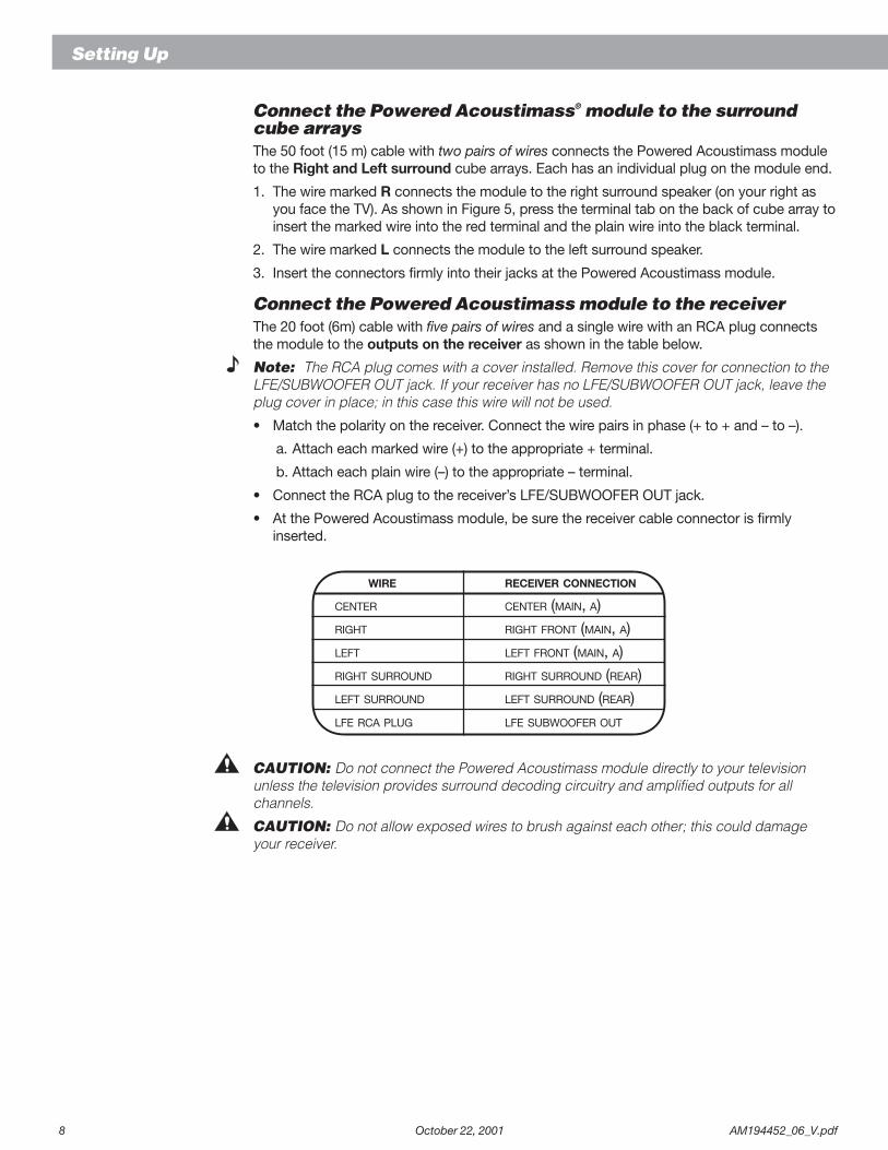
Connect the Powered Acoustimass module to the receiverThe 20 foot (6m) cable with five pairs of wires and a single wire with an RCA plug connectsthe module to the outputs on the receiver as shown in the table below.
Note: The RCA plug comes with a cover installed. Remove this cover for connection to theLFE/SUBWOOFER OUT jack. If your receiver has no LFE/SUBWOOFER OUT jack, leave theplug cover in place; in this case this wire will not be used.
• Match the polarity on the receiver. Connect the wire pairs in phase (+ to + and – to –).
a. Attach each marked wire (+) to the appropriate + terminal.
b. Attach each plain wire (–) to the appropriate – terminal.
• Connect the RCA plug to the receiver’s LFE/SUBWOOFER OUT jack.
• At the Powered Acoustimass module, be sure the receiver cable connector is firmlyinserted.
WIRE RECEIVER CONNECTION
CENTER CENTER (MAIN, A)RIGHT RIGHT FRONT (MAIN, A)
LEFT LEFT FRONT (MAIN, A)RIGHT SURROUND RIGHT SURROUND (REAR)LEFT SURROUND LEFT SURROUND (REAR)
LFE RCA PLUG LFE SUBWOOFER OUT
CAUTION: Do not connect the Powered Acoustimass module directly to your televisionunless the television provides surround decoding circuitry and amplified outputs for allchannels.
CAUTION: Do not allow exposed wires to brush against each other; this could damageyour receiver.
AM194452_06_V.pdf October 22, 2001 9
Setting Up
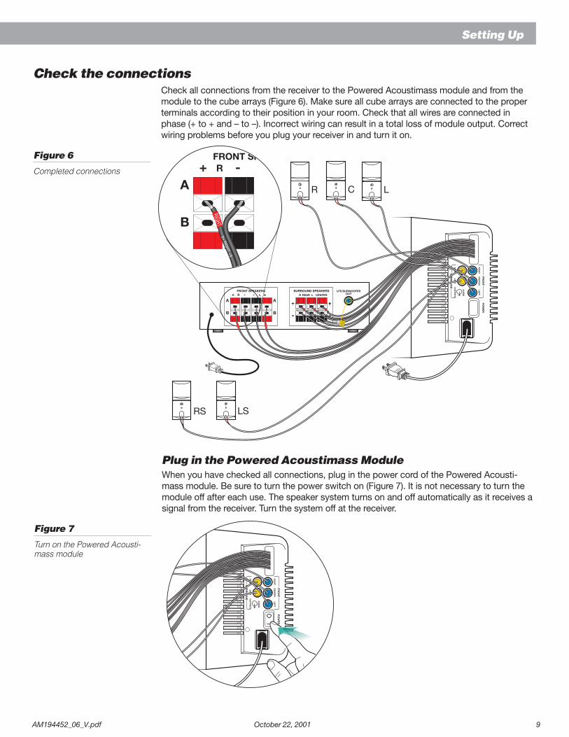
Check the connectionsCheck all connections from the receiver to the Powered Acoustimass module and from themodule to the cube arrays (Figure 6). Make sure all cube arrays are connected to the properterminals according to their position in your room. Check that all wires are connected inphase (+ to + and – to –). Incorrect wiring can result in a total loss of module output. Correctwiring problems before you plug your receiver in and turn it on.
Figure 6
Completed connections
Plug in the Powered Acoustimass ModuleWhen you have checked all connections, plug in the power cord of the Powered Acousti-mass module. Be sure to turn the power switch on (Figure 7). It is not necessary to turn themodule off after each use. The speaker system turns on and off automatically as it receives asignal from the receiver. Turn the system off at the receiver.
Figure 7
Turn on the Powered Acousti-mass module
SURROUND SPEAKERSR CENTER
FRONT SPEAKERSR L LREAR
FRONT SPEAKER
3+ RIG
HT +3
LFE/SUBWOOFEROUT
10 October 22, 2001 AM194452_06_V.pdf
Using Your Acoustimass® 15 Speakers
For realistic home theater sound
LFE level controlThe LFE level control on your Powered Acoustimass module increases or decreases therelative level of low frequency effects on movie soundtracks. Use it to regulate the presenceof these underlying deep bass sounds. You may find it unnecessary to adjust this control. Thefactory, or detent setting is appropriate for a majority of listening situations.
Bass controlThe Bass control on your Powered Acoustimass module can help you customize yourlistening room. Turning the control to the right will add bass to the sound in rooms that mightbe characterized as too shrill. Turning down the control will “brighten” the listening room. Aswith the LFE level control, you may find the factory setting to be completely appropriate foryour listening room.
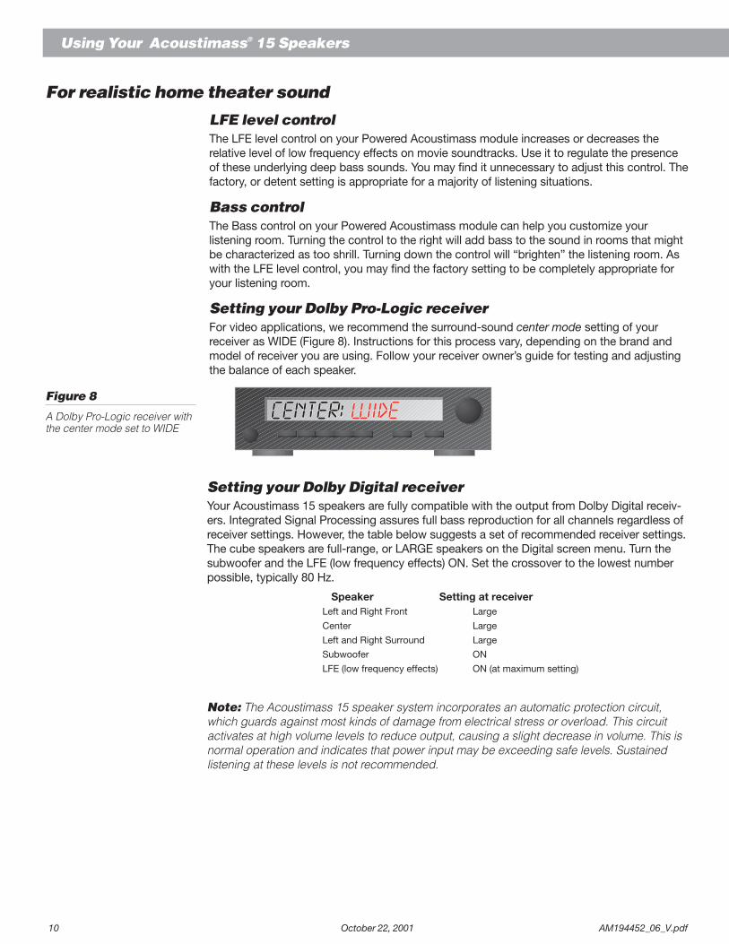
Setting your Dolby Pro-Logic receiverFor video applications, we recommend the surround-sound center mode setting of yourreceiver as WIDE (Figure 8). Instructions for this process vary, depending on the brand andmodel of receiver you are using. Follow your receiver owner’s guide for testing and adjustingthe balance of each speaker.
Figure 8
A Dolby Pro-Logic receiver withthe center mode set to WIDE
Setting your Dolby Digital receiverYour Acoustimass 15 speakers are fully compatible with the output from Dolby Digital receiv-ers. Integrated Signal Processing assures full bass reproduction for all channels regardless ofreceiver settings. However, the table below suggests a set of recommended receiver settings.The cube speakers are full-range, or LARGE speakers on the Digital screen menu. Turn thesubwoofer and the LFE (low frequency effects) ON. Set the crossover to the lowest numberpossible, typically 80 Hz.
Speaker Setting at receiverLeft and Right Front Large
Center Large
Left and Right Surround Large
Subwoofer ON
LFE (low frequency effects) ON (at maximum setting)
Note: The Acoustimass 15 speaker system incorporates an automatic protection circuit,which guards against most kinds of damage from electrical stress or overload. This circuitactivates at high volume levels to reduce output, causing a slight decrease in volume. This isnormal operation and indicates that power input may be exceeding safe levels. Sustainedlistening at these levels is not recommended.
AM194452_06_V.pdf October 22, 2001 11
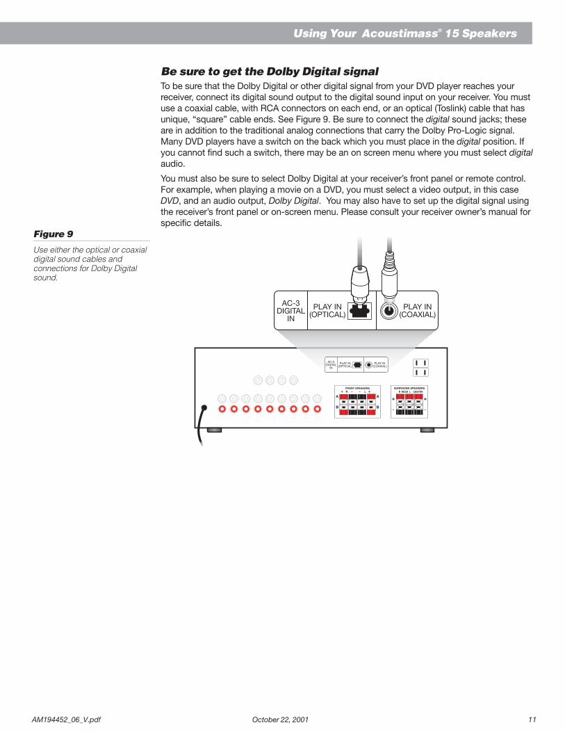
Be sure to get the Dolby Digital signalTo be sure that the Dolby Digital or other digital signal from your DVD player reaches yourreceiver, connect its digital sound output to the digital sound input on your receiver. You mustuse a coaxial cable, with RCA connectors on each end, or an optical (Toslink) cable that hasunique, “square” cable ends. See Figure 9. Be sure to connect the digital sound jacks; theseare in addition to the traditional analog connections that carry the Dolby Pro-Logic signal.Many DVD players have a switch on the back which you must place in the digital position. Ifyou cannot find such a switch, there may be an on screen menu where you must select digitalaudio.
You must also be sure to select Dolby Digital at your receiver’s front panel or remote control.For example, when playing a movie on a DVD, you must select a video output, in this caseDVD, and an audio output, Dolby Digital. You may also have to set up the digital signal usingthe receiver’s front panel or on-screen menu. Please consult your receiver owner’s manual forspecific details.
Figure 9
Use either the optical or coaxialdigital sound cables andconnections for Dolby Digitalsound.
SURROUND SPEAKERSR CENTER
FRONT SPEAKERSR L LREAR
AC-3DIGITAL
IN
PLAY IN(OPTICAL)
PLAY IN(COAXIAL)
AC-3DIGITAL
IN
PLAY IN(OPTICAL)
PLAY IN(COAXIAL)
Using Your Acoustimass® 15 Speakers
12 October 22, 2001 AM194452_06_V.pdf
TroubleshootingIf you have a problem with your Acoustimass 15 speakers, turn off your sound source and trythe solutions below. If you still have a problem, contact your Bose® dealer to arrange forservice. To contact Bose directly, refer to the inside back cover of this guide.
Problem What to do
System does not function at all • Make sure the receiver and Powered Acoustimass module are pluggedinto an operating AC wall outlet and that the units are turned on.
• Be sure to select a source at the receiver (video, CD, DVD, tuner).
No sound • Check the speaker connections.• Turn the Powered Acoustimass module ON.• For digital sound, be sure a coaxial or optical cable connects the digital
output of the DVD player with the digital input on your receiver.• Be sure the audio source selected is correct. For example: select DVD
audio on your receiver and player for DVD sound.• Disconnect any headphones.• Increase the volume.
No sound from cube arrays • Be sure the Powered Acoustimass module is plugged in and turned on.
Sound is distorted • Make sure speaker wire is not damaged.• Reduce the volume of external components connected to the receiver.
No bass • Make sure the speaker connections at the receiver or amplifier are correct(+ to + and – to –).
Not enough or too much bass • Move the Powered Acoustimass module closer to a wall or corner toincrease bass. Move it farther away from a wall or corner to decrease bass.
• Adjust the LFE level control.
No surround-sound • Be sure your receiver is processing a signal from a Hi-Fi VCR, stereo TV,laserdisc, or DVD player, or other surround-sound source. If you are usingthe Dolby Pro-Logic mode, check that surround-sound is turned ON. Ifyou are using Digital programming, verify that the settings are correct at thereceiver. Be sure the source material (DVD, laser disc, or broadcast pro-gramming) is Dolby Digital encoded.
Customer serviceFor additional help in solving problems, contact Bose customer service. See the inside backcover for Bose customer service offices and phone numbers.
Cleaning the speakersThe cabinets of your Acoustimass 15 speaker system may be cleaned with a soft damp cloth.Do not use any sprays near the system or allow liquids to spill into any openings. Also, do notuse any solvents, chemicals, or cleaning solutions containing alcohol, ammonia, or abrasives.
The grille assemblies on the cube arrays may be carefully vacuumed, if necessary. Pleasenote that the drivers are located directly behind the grille cloth, and are easily damaged ifreasonable care is not taken.
Maintaining Your Acoustimass® 15 Speakers
AM194452_06_V.pdf October 22, 2001 13
Product Information
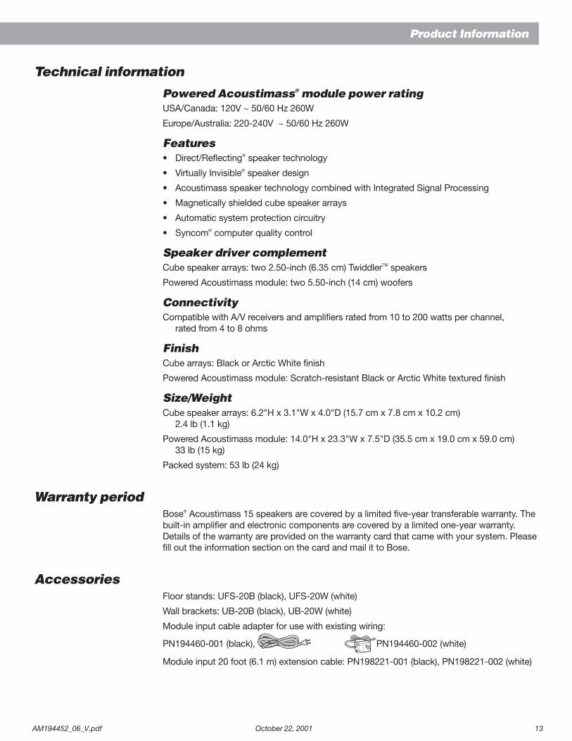
Technical information
Powered Acoustimass® module power ratingUSA/Canada: 120V ~ 50/60 Hz 260W
Europe/Australia: 220-240V ~ 50/60 Hz 260W
Features• Direct/Reflecting® speaker technology
• Virtually Invisible® speaker design
• Acoustimass speaker technology combined with Integrated Signal Processing
• Magnetically shielded cube speaker arrays
• Automatic system protection circuitry
• Syncom® computer quality control
Speaker driver complementCube speaker arrays: two 2.50-inch (6.35 cm) TwiddlerTM speakers
Powered Acoustimass module: two 5.50-inch (14 cm) woofers
ConnectivityCompatible with A/V receivers and amplifiers rated from 10 to 200 watts per channel,
rated from 4 to 8 ohms
FinishCube arrays: Black or Arctic White finish
Powered Acoustimass module: Scratch-resistant Black or Arctic White textured finish
Size/WeightCube speaker arrays: 6.2"H x 3.1"W x 4.0"D (15.7 cm x 7.8 cm x 10.2 cm)
2.4 lb (1.1 kg)
Powered Acoustimass module: 14.0"H x 23.3"W x 7.5"D (35.5 cm x 19.0 cm x 59.0 cm)33 lb (15 kg)
Packed system: 53 lb (24 kg)
Warranty periodBose® Acoustimass 15 speakers are covered by a limited five-year transferable warranty. Thebuilt-in amplifier and electronic components are covered by a limited one-year warranty.Details of the warranty are provided on the warranty card that came with your system. Pleasefill out the information section on the card and mail it to Bose.
AccessoriesFloor stands: UFS-20B (black), UFS-20W (white)
Wall brackets: UB-20B (black), UB-20W (white)
Module input cable adapter for use with existing wiring:
PN194460-001 (black), PN194460-002 (white)
Module input 20 foot (6.1 m) extension cable: PN198221-001 (black), PN198221-002 (white)

1
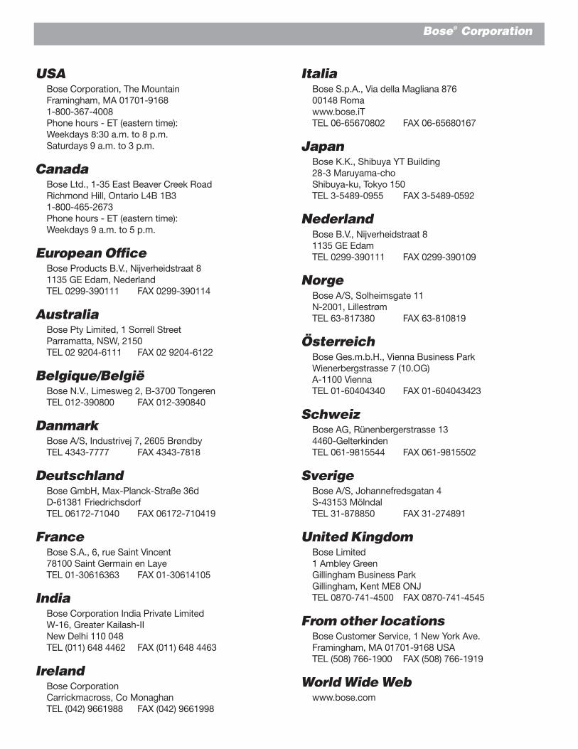
Bose® Corporation
ItaliaBose S.p.A., Via della Magliana 87600148 Romawww.bose.iTTEL 06-65670802 FAX 06-65680167
JapanBose K.K., Shibuya YT Building28-3 Maruyama-choShibuya-ku, Tokyo 150TEL 3-5489-0955 FAX 3-5489-0592
NederlandBose B.V., Nijverheidstraat 81135 GE EdamTEL 0299-390111 FAX 0299-390109
NorgeBose A/S, Solheimsgate 11N-2001, LillestrømTEL 63-817380 FAX 63-810819
ÖsterreichBose Ges.m.b.H., Vienna Business ParkWienerbergstrasse 7 (10.OG)A-1100 ViennaTEL 01-60404340 FAX 01-604043423
SchweizBose AG, Rünenbergerstrasse 134460-GelterkindenTEL 061-9815544 FAX 061-9815502
SverigeBose A/S, Johannefredsgatan 4S-43153 MölndalTEL 31-878850 FAX 31-274891
United KingdomBose Limited1 Ambley GreenGillingham Business ParkGillingham, Kent ME8 ONJTEL 0870-741-4500 FAX 0870-741-4545
From other locationsBose Customer Service, 1 New York Ave.Framingham, MA 01701-9168 USATEL (508) 766-1900 FAX (508) 766-1919
World Wide Webwww.bose.com
USABose Corporation, The MountainFramingham, MA 01701-91681-800-367-4008Phone hours - ET (eastern time):Weekdays 8:30 a.m. to 8 p.m.Saturdays 9 a.m. to 3 p.m.
CanadaBose Ltd., 1-35 East Beaver Creek RoadRichmond Hill, Ontario L4B 1B31-800-465-2673Phone hours - ET (eastern time):Weekdays 9 a.m. to 5 p.m.
European OfficeBose Products B.V., Nijverheidstraat 81135 GE Edam, NederlandTEL 0299-390111 FAX 0299-390114
AustraliaBose Pty Limited, 1 Sorrell StreetParramatta, NSW, 2150TEL 02 9204-6111 FAX 02 9204-6122
Belgique/BelgiëBose N.V., Limesweg 2, B-3700 TongerenTEL 012-390800 FAX 012-390840
DanmarkBose A/S, Industrivej 7, 2605 BrøndbyTEL 4343-7777 FAX 4343-7818
DeutschlandBose GmbH, Max-Planck-Straße 36dD-61381 FriedrichsdorfTEL 06172-71040 FAX 06172-710419
FranceBose S.A., 6, rue Saint Vincent78100 Saint Germain en LayeTEL 01-30616363 FAX 01-30614105
IndiaBose Corporation India Private LimitedW-16, Greater Kailash-IINew Delhi 110 048TEL (011) 648 4462 FAX (011) 648 4463
IrelandBose CorporationCarrickmacross, Co MonaghanTEL (042) 9661988 FAX (042) 9661998

© 2000 Bose Corporation, The Mountain,Framingham, MA 01701-9168 USA194452 AM Rev. 06 JN98831