Embed Size (px)
Citation preview

The Board of Water Commissioners
Engineering Standards 16th Edition
Effective July 29, 2021
For use in the Denver Water service area

The Engineering Standards, 16th Edition, of the Board of Water Commissioners, Denver, Colorado, are
binding and in full force and effect as of June 2021. These Standards establish standard requirements for
service lines, transmission and distribution mains, and conduits. Where applicable, use these Standards in
conjunction with the latest version of Denver Water’s Capital Projects Construction Standards (CPCS).
Denver Water is not responsible for the use of all or any portion of this document by any other public agency
or private entity. No representation or warranty of any kind is made concerning the accuracy,
completeness, suitability, or utility of any information or product referenced in this document, and Denver
Water assumes no liability arising from such use.

INTENTIONALLY BLANK
i
Contents
Contents i
Terms and Definitions 1
Shortened Word Forms 7
Chapter 1: General 9 1.01 Authority 9 1.02 Effective Date of Standards 9 1.03 Revisions, Amendments, or Additions 9 1.04 Denver Water Control 9 1.05 Organization and Interpretation of Standards 9 1.06 Sustainability 9
Chapter 2: Main Extensions and Distributor Main Extensions 10 2.01 General 10 2.02 Applicable Engineering Standards 10 2.03 Application Procedure 10 2.04 Plans 10 2.05 Engineering 10 2.06 Construction Procedure 11 2.07 Surveying 12 2.08 Placing Survey Lines 12 2.09 Inspection 12 2.10 Contractors 13 2.11 Points of Delivery 13 2.12 Special Conditions 13
Chapter 3: Service Lines, Fire Service Lines, Meters, and Appurtenances 14 3.01 General 14 3.02 Layout of Service Lines 14 3.03 Separate Trenches 15 3.04 Combination Service Lines 15 3.05 Pumps 16 3.06 Tanks 16 3.07 Connections for Water 16 3.08 Taps and Saddles 17 3.09 Size 17 3.10 Pipe Material 18 3.11 Curb Stops, Valves, and Valve Boxes 18 3.12 Meters 18
ii
3.13 Automatic Meter Reading and Automatic Metering Infrastructure Equipment 19 3.14 Outside Meter Setting 19 3.15 Inside Meter Setting 19 3.16 Meter Bypass Lines 20 3.17 Construction 20 3.18 Abandonment or Removal of Service Lines and Tap Cuts 21 3.19 Disinfection Requirements for Recycled Conversion Projects 21
Chapter 4: Easements and Licenses 22 4.01 Granting an Easement to Denver Water 22 4.02 Granting an Easement to a Distributor 22 4.03 Acquiring an Easement from Denver Water 22 4.04 Obtaining a License to Use or Cross Denver Water Property 23
Chapter 5: Distribution System Design and Layout 24 5.01 General 24 5.02 Quality of the Distribution System 24 5.03 Size of Distribution Mains 24 5.04 Fire Protection Systems 25 5.05 Backflow Prevention and Cross-Connection Control Program 25 5.06 Operating Pressures within the Distribution System 27 5.07 Pressure Regulating Valves 27 5.08 Storage Facilities 27 5.09 Electric Pump Motors 28 5.10 Pumping Facilities 28 5.11 Distribution System Layout 28 5.12 Isolation Valves 29 5.13 Connections to Conduits 30 5.14 Supervisory Control and Data Acquisition 30 5.15 Interconnects with Other Water Systems 30 5.16 Flow Measurement 30
Chapter 6: Materials 31 6.01 General 31 6.02 Size of Mains 31 6.03 Pipe Classes 31 6.04 Selection of Pipe 31 6.05 Pipe Fittings 32 6.06 Isolation Valves 33 6.07 Pressure Regulating Valves 33 6.08 Tapping Valves and Sleeves 33 6.09 Check Valves 33 6.10 Stop and Waste Valves 33
iii
6.11 Valve Boxes 34 6.12 Valve Reference Marker Posts 34 6.13 Water Meters 34 6.14 Meter Appurtenances 34 6.15 Meter Pits and Lids for 3/4 Inch and 1-Inch Meters 35 6.16 Meter Vaults for 1 1/2 Inch and Larger Meters 36 6.17 Concrete Structures 36 6.18 Steel Reinforcement for Concrete 36 6.19 Manholes 36 6.20 Manhole Base Slabs and Base Beams 37 6.21 Sump Pits for Vaults and Manholes 37 6.22 Vent Pipes 37 6.23 Manufacturers and Models of Fire Hydrants 37 6.24 Fire Service Line Connections to Mains 37 6.25 Service Lines 38 6.26 Corporation Stops 38 6.27 Curb Stop Service Boxes 38 6.28 Cathodic Protection Systems 38 6.29 Kickblocks 39 6.30 Protective Concrete Pads Over Pipe 39 6.31 Pipe Insulation 39 6.32 Casing Pipe 39 6.33 Carrier Pipe 39 6.34 Miscellaneous Metalwork and Piping 39 6.35 Air and Vacuum Valves 40
Chapter 7: Earthwork 41 7.01 Exploratory Excavation 41 7.02 Excavation to Line and Grade 41 7.03 Trenching Operations 41 7.04 Excavation for Structures 41 7.05 Blasting 41 7.06 Dewatering 42 7.07 Foundations on Unstable Soil 42 7.08 Pipe Bedding and Pipe Zone Material 42 7.09 Backfill and Compaction 42 7.10 Controlled Low Strength Material 43 7.11 Cleanup 43 7.12 Surface Restoration 43 7.13 Subgrade and Road Preparation 43
Chapter 8: Pipe Installation 44 8.01 Handling of Materials 44
iv
8.02 Preparation for Installation 44 8.03 Cutting and Fitting of Pipe 44 8.04 Pipe Alignment and Grade 44 8.05 Deviation Occasioned by Other Structures 44 8.06 Temporary Bulkheads and Pneumatic Plugs 45 8.07 Frost 45 8.08 Ductile Iron Pipe 45 8.09 Polyvinyl Chloride Pressure Pipe 46 8.10 Valves and Valve Boxes 46 8.11 Fittings 46 8.12 Tapping Sleeves 46 8.13 Fire Hydrants 46 8.14 Fire Service Line Connections 47 8.15 Kickblocks 47 8.16 Concrete Structures 47 8.17 Reinforcing Steel for Concrete Structures 49 8.18 Joint Restraint Devices 49 8.19 Connections to Denver Water's System 49 8.20 Cathodic Protection Systems 50 8.21 Chlorination 50 8.22 Hydrostatic Testing 51 8.23 Acceptance and Release for Taps 52 8.24 Blowoff Assembly 52 8.25 Sewer Crossings 52 8.26 Trenchless Installation 52 8.27 Horizontal Directional Drilling 53 8.28 Pipe Bursting 53
Chapter 9: Transmission Mains 55 9.01 General 55 9.02 Other Applicable Standards 55 9.03 Design 55 9.04 Plans 55 9.05 Materials 55 9.06 Installation 55 9.07 Sewer Crossings 56 9.08 Easement Width Requirements 56
Chapter 10: Conduits 57 10.01 General 57 10.02 Other Applicable Standards 57 10.03 Preliminary Investigation 57 10.04 Design 58
v
10.05 Plans and Specifications 58 10.06 Materials 58 10.07 Installation 58 10.08 Sewer Crossings 59 10.09 As-Constructed Drawings 59 10.10 Easement Width Requirements 59
Chapter 11: Recycled System 60 11.01 Other Applicable Standards 60 11.02 Water Quality 60 11.03 Potable Water Backup 60 11.04 Conversion from a Potable Line to a Recycled Line 60 11.05 Protection of the Potable System 60 11.06 Discharges from the System 60 11.07 User Permits 60 11.08 Denver Water Owned Recycled Water Mains 60 11.09 Recycled Pipe Color 61 11.10 Underground Utility Warning Tape 62 11.11 Tracer Wire 62 11.12 Pipe Lining 62 11.13 Recycled Water Service Lines and Appurtenances 62 11.14 Recycled Water Customer Guidelines 63 11.15 Dual Supply Systems 64
Chapter 12: Integrated System 65 12.01 General 65 12.02 Maintenance Programs 65 12.03 Distribution System Compliance Monitoring 65 12.04 Online Water Quality Monitoring 65 12.05 Facility Operation and Status 65 12.06 Distribution System Discharges 66
Appendix A: Reference List of CPCS Specifications and CPCS Details
Appendix B: Plan Requirements for Main Extensions and Service Lines
Appendix C: Easement Requirements
Appendix D: System Design and Layout for Backflow Prevention and Cross-Connection Control Program
Appendix E: District Ownership and Operations
Appendix F: Pumping Facilities
Appendix G: SCADA Standards and Practices
Appendix H: Procedure for the Evaluation of Materials

INTENTIONALLY BLANK
1
Terms and Definitions
As used in these Standards, unless the context otherwise requires, the words defined herein have the following meanings ascribed:
A advanced metering infrastructure: An integrated system of smart meters, communications networks, and data management systems that enables two-way communication between utilities and customers. Also called AMI. air-gap: The unobstructed vertical distance between the lowest opening from any pipe or faucet supplying water to a tank, plumbing fixture, or other assembly, and the flood level rim of said vessels. Permanently install an approved air-gap that is at least double the diameter of the supply pipe, measured vertically, above the top of the overflow rim of the vessel, but not less than 1 inch. American Backflow Prevention Association BFPA tester: A tester certified in the field test procedures published in the current Manual of Cross-Connection Control published by the USC FCCCHR who is proficient in field test procedures and the preparation of assembly test reports.
American Society of Sanitary Engineering BFPA tester: A tester certified in the field test procedures meeting the minimum performance requirements of the ASSE Series 5000 who is proficient in test procedures and the preparation of assembly test reports.
atmospheric vacuum breaker: A type of BFPA that is not approved by Denver Water.
automatic meter reading: A type of AMI. A system of electronic components that allow the collection of meter readings by wireless or wired electronic communication systems. Components thereof may be attached to and become part of a customer’s water meter. Other components may include central data collection units, vehicle-mounted equipment, and data transmission systems. Also called AMR.
B backflow: The flow of water or other liquids, mixtures, gases, or substances into the distribution pipes of a potable water supply from a source other than the intended source.
backflow prevention: The prevention of the flow of any foreign liquids, gases, or substances into the pipelines of a potable water supply by the installation of a BFPA or method. Also called BFPA.
backpressure: An increase in pressure in the downstream piping system that can cause a reversal in the normal direction of flow at a particular point. The increase in pressure can be caused by pumping, air pressure, or the elevation of piping.
backsiphonage: A form of backflow that is a result of negative or sub-atmospheric pressure within the water system.
Board: The Board of Water Commissioners established by the Charter of the City and County of Denver or its authorized representative.
C Capital Projects Construction Standards: Standards that apply to the design and construction of Denver Water’s capital projects. These multidisciplinary standards include General Conditions, Standard Technical Specifications, and Standard Details that apply to individual project contract documents but are not printed with them. Also called CPCS. CEO/Manager: The Board designated CEO/Manager of Denver Water.
2
certified welder: A skilled welder, welding operator, or tacker with adequate experience in the method of materials to be used and qualified under the requirements of the AWS D1.1 using the test position in which the weld is to be performed. Welders shall be qualified by an independent, local, and approved testing agency within the 6-month period prior to beginning work. Machines and electrodes like those used in the work shall be used in qualification tests. commercial property: Real estate zoned with a primary use including, but not limited to, business, commercial, industrial, public, manufacturing, and mixed-use (commercial/residential) properties.
conduit: A 24 inch or larger diameter pipe that carries recycled, raw, or potable water to and from treatment facilities and storage reservoirs and to delivery points that supply the distribution system; distinguished from transmission mains due to head loss constraints.
consecutive system: A public water system that receives some or all of its finished water from one or more wholesale systems. Delivery may be through a direct connection or through the distribution system of one or more consecutive systems.
consumer: A person, firm, or corporation using or receiving water from the public water system.
contamination: Treated water quality compromised by sewage, industrial fluids, waste liquids, compounds, or other materials that creates an actual or potential hazard to public health.
Contractor: In the context of these Standards, a Contractor is used for a water system extension.
corrective action: Risk assessment, active remediation, passive remediation, voluntary cleanup, investigation, and/or monitoring of environmental contamination.
cross-connection control: An administered program that is designed to protect the public health, the public water system, and the recycled distribution system by the regulation and monitoring of the installation and maintenance of the BFPA or method.
cross-connection control containment by isolation: The installation of a low hazard USC FCCCHR DC BFPA or method to serve as containment and a high hazard USC FCCCHR RP BFPA to serve as isolation. Installation on a designated branch line as an acceptable means of protecting private plumbing and the public water system is at the discretion of Denver Water.
cross-connection control containment protection: The installation of a USC FCCCHR approved BFPA or method on a dedicated water service line that protects the public water system from an actual or potential cross-connection within a private plumbing system.
cross-connection control isolation protection: The installation of a USC FCCCHR approved BFPA within a building or facility’s private plumbing system near the sources of pollution or contamination to protect the internal plumbing from an actual or potential cross-connection.
D degree of hazard: A pollutant, or non-health risk, is considered a low hazard. A contaminant, or health risk, is considered a high hazard. Classifications are determined based on conditions within a system.
Denver: Inside the territorial limits of the City and County of Denver, Colorado. Denver Water: The property and personnel under control of the Board as defined by Article 10.1.6 of the Charter.
distribution main: A 12 inch or smaller diameter pipe that is installed in public ROW or easement and used for the distribution of water to consumers.
distribution main valve: A valve on a distribution main that is direct buried.
distribution system: Mains composed of 12 inch or smaller diameter pipe, together with appurtenant and necessary valves, fire hydrants, taps, meters, service pipes, and associated materials, property, and equipment that receive recycled or potable water from conduits and transmission mains for delivery to consumers.
3
Distributor: An entity that is located outside the City and County of Denver yet inside the service area that has a contract with Denver Water for the delivery of potable water and does not comingle such water with potable water from any other source.
Distributor Contract Area: An area outside the City and County of Denver covered by a contract that furnishes potable or nonpotable water to an entity.
Distributor main extension: An extension to a distribution system that is within a Distributor Contract Area and outside the territorial boundaries of the City and County of Denver and Total Service Contract Area.
Division: An organizational subdivision of Denver Water (e.g., Engineering Division).
domestic service line: Pipe, fittings, and appurtenances used to convey water from the tap on Denver Water’s or a Distributor’s facilities to the plumbing of licensed premises for human consumption.
double check valve assembly: A testable assembly comprised of two internally loaded, independently operating check valves between two tightly closing resilient-seated shutoff valves and four properly located test cocks for field testing. The unit shall be a USC FCCCHR approved BFPA designed to protect against a non-health hazard condition.
dual water supply: A water supply that is located on or is available to a customer’s premises in addition to the Denver Water approved public potable water supply (e.g., gray water, raw water, recycled water, well water, a lake, a pond, or a ditch).
dual water supply agreement: An agreement between the Board and the Property Owner declaring the premises has or may have a dual water supply other than Denver Water’s potable system.
E Engineer: The Chief Engineering Officer who is a member of the CEO’s/Manager's Executive Staff, or the Chief’s appointed representative.
environmental contamination: The presence of any hazardous material, including, but not limited to, any substances defined as or included in the definition of “hazardous substance,” “hazardous material,” or “toxic substances” in the Comprehensive Environmental Response, Compensation, and Liability Act, 42 U.S.C. § 9601, et seq., the Hazardous Materials Transportation Act, 49 U.S.C. § 5101, et seq., the Resource Conservation and Recovery Act, 42 U.S.C. § 6901, et seq., or any other federal, state or local statute, law, ordinance, code, rule, regulation, order, decree or other requirement of governmental authority regulating, relating to or imposing liability or standard of conduct concerning any hazardous, toxic, or dangerous substance or material, as now or at any time hereafter in effect, and in the regulations adopted, published, and/or promulgated pursuant to said laws.
F fire service line: Pipe, fittings, and appurtenances used to convey water from distribution mains to the licensee for fire protection purposes (i.e., automatic sprinkler systems). For these Standards, the NFPA 13 fire service line extends from the corporation stop or tee on the water main to the edge of the public ROW or easement that contains the water main.
H head loss: The measure of the reduction in the total head of the water as it moves through a system. In the Denver Water system, head loss constraints are as follows: 2 feet per thousand in distribution mains, 1 1/2 feet per thousand in transmission mains, and 1 foot per thousand in conduits.
high hazard: Vulnerability from a facility’s private plumbing system that constitutes a health risk to the internal plumbing and/or the public water system by the introduction of a contaminant (e.g.,

4
sewage, industrial fluids, waste liquids, compounds, or other materials). The introduction of such contaminant would cause a poisoning of the water supply or the spread of disease.
hydrant branch: Pipe that extends from the water main to the fire hydrant.
hydraulic grade line: In closed pipelines flowing under pressure, it is the level to which water would rise in a vertical tube open to atmospheric pressure at any point along the pipeline.
I industrial piping system: Any system used by a consumer for the transmission, confinement, or storage of any fluid, solid, or gaseous substance other than an approved water supply. This includes pipes, conduits, tanks, receptacles, fixtures, equipment, and appurtenances used to produce, convey, or store substances that may be polluted or contaminated.
Inspector: The authorized representative of the Engineer assigned to a jobsite.
integrated system: A system that consists of a wholesale system and one or more consecutive systems with distribution systems that are physically connected, where the wholesaler has assumed responsibility for compliance with one or more of the regulatory requirements applicable to the supplier responsible for the consecutive system by written agreement.
irrigation service line: Pipes, fittings, and appurtenances used to convey water from the tap on Denver Water’s or a Distributor’s facilities to the plumbing of the licensed premises for irrigation use.
isolation valve: A valve used in a fully open or fully closed position to isolate the flow of water.
L licensee: Any person, association, corporation, entity, or governmental agency that owns or controls the licensed premises.
low hazard: Vulnerability from a facility’s private plumbing system that may constitute a nuisance or cause damage to the internal plumbing and/or public water system but is not a public health risk.
M main extension: An extension to the distribution system that is within the City and County of Denver or Total Service Contract Area.
manifold tap: A physical device, pipe fitting or connection that connects to a distribution main and branches off to serve multiple licensee-owned service lines and meter pits, each of which then serves a single property within a common interest of community.
Master Meter Contract Area: An area in which, by contract, a Distributor is responsible for the construction, operation, and maintenance of the water distribution system, reads the customer’s meter, and bills the customer.
Meter Inspector: An authorized representative of Denver Water’s Customer Service Field Section responsible for ensuring that water services and metering installations, including AMR/AMI systems, are in compliance with applicable standards.
multi-family residential: A multiple-unit residential structure consisting of attached dwelling units arranged side-by-side or vertically stacked adjacent to a public ROW or easement.
N non-toxic substance: Any substance of a non-poisonous nature that may create a low hazard to the water supply system.
5
O Operating Rules: Rules adopted by the Board under Article 10.1.18 of the Charter of the City and County of Denver that define how Denver Water conducts business.
Outside Denver: Outside the territorial limits of the City and County of Denver. Owner: The legal owner of a parcel of land as reflected in the county assessor’s records.
P plans: Engineered drawings that show the location, dimensions, materials, and details of the proposed work.
pollution: An impairment to the quality of water to a degree that does not create an actual hazard to the public health but does adversely and unreasonably affect such water for domestic use.
premises: A legally defined land parcel that may have more than one tap, meter, and license.
premises ID: A randomly assigned unique identifier for the individual service address of a physical location. Also called PID.
pressure vacuum breaker: Designed to prevent backsiphonage, it is a testable assembly consisting of an internally loaded check valve, a loaded air inlet valve, two resilient seated shut off valves and two appropriately located test cocks. Do not expose this type of assembly to backpressure. Professional Engineer: An engineer registered in the State of Colorado. Also called PE.
Professional Land Surveyor: A land surveyor registered in the State of Colorado. Also called PLS.
R Read and Bill Contract Area: An area in which, by contract, the Distributor is responsible for the operation and maintenance of the water distribution system. Denver Water reads the meter of the customer and bills the customer according to a specified rate.
reduced pressure principle backflow prevention assembly: A testable assembly comprised of two internally loaded, independently operating check valves, a mechanically independent differential pressure relief valve located between two check valves, two tightly closing upstream and downstream resilient-seated shutoff valves, and four properly located test cocks for the field testing. The unit shall be a USC FCCCHR approved BFPA designed to protect against a non-health and/or health hazard condition. Also called RP BFPA.
residential fire sprinkler suppression system: An integrated piping system used for fire protection purposes to improve and increase public safety. The integrated system shall be in accordance with NFPA 13D.
S Section: An organizational subdivision of Denver Water (e.g., Sales Administration Section).
service area: The City and County of Denver plus the area within the outer geographical boundaries of the existing and projected service areas of all the Distributors combined based on the legal descriptions contained in each Distributor’s contract.
service line: The pipe, fittings, and appurtenances used to convey water from the tap on Denver Water’s or a Distributor’s facilities to the plumbing of a licensed premises.
single-family residential: A single unit dwelling.
6
stop box: A valve box, service box, or curb box that is set over the property line valve or curb stop on a domestic water service.
stub-in: A connection to a main intended to allow for the installation of a portion of the service line for 2 inch and smaller taps prior to setting the meter and activating the license for a particular premises.
subgrade: The elevation at the bottom of pavement depth.
T tap: A physical device, pipe fitting, or connection that connects a licensee-owned service line to a distribution main owned by Denver Water or a Distributor or to a fire service line.
Total Service Contract Area: An area in which, by contract, Denver Water is responsible for the operation and maintenance of the water distribution system, reads the meter of the customer, and bills the customer.
toxic substance: Any liquid, solid, or gaseous substance, including raw sewage, that may create a danger to the health and well-being of the consumer when introduced into the water supply system.
transmission main: A 16 inch through 20 inch diameter pipe that receives recycled, raw, or potable water from a conduit and distributes it to consumers in public ROW or easement; distinguished from conduits and distribution mains due to head loss constraints.
transmission main valve: A 16 inch through 20-inch valve typically contained within a vault.
W water feature: A structural design element that is not intended for human contact. It shall be supplied by potable or recycled water and may be located indoors or outdoors (e.g., ponds, cascades, waterfalls, and streams normally powered by pumps). Tapping the service line off an irrigation or recycled system is subject to approval by Denver Water.
water play feature: A structural design element (e.g., an interactive fountain) intended for recreational use (human contact) that is supplied with potable water normally powered by pumps. The use of irrigation, fire, and/or recycled water is prohibited.
water – potable: Water from a source that is approved for human consumption by the official health authority having jurisdiction.
water – recycled: Treated domestic wastewater that is suitable for irrigation and commercial uses but is not suitable for human consumption.
water main: A distribution or transmission main.
water service connection: The terminal end of a service connection (i.e., where Denver Water loses jurisdiction and quality control over the water at its point of delivery to the customer’s system). The water service connection is at the downstream end of the meter. Also included are connections from a fire hydrant, fire service line, and any other temporary or emergency water service connection from Denver Water’s potable system. Unprotected taps on the service upstream of the meter or BFPA are prohibited.
water supply – unapproved: Water from a source that is not approved for human consumption by the official health authority having jurisdiction.
welder: See certified welder.
wholesale system: For the purposes of the integrated system, Denver Water is a wholesale system. For wholesale systems, the wholesaler is responsible for complying with all of the applicable requirements of the Colorado Primary Drinking Water Regulations up to the point where treated drinking water from the wholesale system enters a consecutive system.
7
Shortened Word Forms
Organizations
ABPA American Backflow Prevention Association ACI American Concrete Institute AISI American Iron and Steel Institute ANSI American National Standards Institute ASSE American Society of Sanitary Engineering ASTM ASTM International AWS American Welding Society AWWA CDOT
American Water Works Association Colorado Department of Transportation
CDPHE Colorado Department of Public Health and Environment CSA Canadian Standards Association DEN Denver International Airport DIPRA FAA
Ductile Iron Pipe Research Association Federal Aviation Administration
IEEE Institute of Electrical and Electronics Engineers, Inc. ISA Instrument Society of Automation MSS Manufacturers Standardization Society NACE National Association of Corrosion Engineers NEC National Electrical Code NEMA National Electrical Manufacturers Association NFPA National Fire Protection Association NSF NSF International OSHA Occupational Safety and Health Administration SSPC The Society for Protective Coatings UL Underwriters Laboratories, Inc. USC FCCCHR University of Southern California Foundation for Cross-Connection Control
and Hydraulic Research
Abbreviations and Acronyms
AC asbestos cement AMI advanced metering infrastructure AMR automatic meter reading AP angle point ASC automatic sprinkler connection AWG American wire gauge BFPA backflow prevention assembly BHN Brinell hardness number Buna-N nitrile CaCO3 calcium carbonate CAD computer aided drafting CI cast iron CLSM controlled low strength material cm centimeter CPCS Capital Projects Construction Standards CPDWR Colorado Primary Drinking Water Regulations cy cubic yard DC direct current, double check valve DCDA double check detector assembly DFT dry film thickness DI ductile iron DR drain; drive; drawer; dimensional ratio EPDM ethylene propylene diene monomer
8
ERT encoder-receiver-transmitter fps feet per second HDD horizontal directional drilling HMWPE high molecular weight polyethylene HVAC heating, ventilating, and air conditioning I&C instrumentation and control I/O inputs and outputs ID inside diameter IRR irrigation L liter lb(s) pound(s) LMDP linear medium density polyethylene m meter mA milliamperes MCL maximum contaminant level mg milligrams MOA miller over all MS Material Specification NAD North American datum NGS national geodetic survey No. number NO normally open NPDES national pollutant discharge elimination system NPT national pipe thread OD outside diameter P&ID piping and instrumentation diagram PC point of curvature PE plain end; Professional Engineer PI point of intersection PID premises ID PLC programmable logic controllers PLS Professional Land Surveyor POT point on tangent ppm parts per million PRV pressure regulating valve psi pounds per square inch PT point of tangency PUD/PBG planned unit development/planned building group PVB pressure vacuum breaker PVC polyvinyl chloride ROW right(s) of way RP BFPA reduced pressure principle backflow prevention assembly SCADA supervisory control and data acquisition SOP standard operating procedure UNS unified numbering system V volts VAC volts alternating current VDC volts direct current WQCD Colorado Water Quality Control Division
9
Chapter 1: General
1.01 Authority The CEO/Manager of Denver Water issues these Standards pursuant to the authority granted by the Charter of the City and County of Denver, as amended. The administration of these Standards, including the interpretation, enforcement, revision, waiver, and variance thereof, is hereby delegated by the CEO/Manager to the Chief Engineering Officer or the Chief’s appointed representative.
NOTE: Submit formal variance requests in writing to the Sales Administration Section and send them to the Chief Engineering Officer, or the Chief’s appointed representative, for review.
1.02 Effective Date of Standards These Standards are effective after they have remained posted in a conspicuous public place in the principal business offices of Denver Water and on Denver Water’s website for a period of 15 days; they supersede the former Engineering Standards of the Board of Water Commissioners, Denver, Colorado.
1.03 Revisions, Amendments, or Additions These Standards may be revised, amended, or added to periodically. Such revisions, amendments, and additions are binding and in full force and effect when posted for a period of 15 days as set forth in 1.02.
1.04 Denver Water Control These Standards apply to the installation, operation, maintenance, and materials of water facilities under the control of Denver Water, including Denver Water property interests outside of Denver or Distributor Contract Areas. Control will be exercised in accordance with the Charter inside Denver, and by contract with Distributor Contract Areas.
Denver Water will not be restricted by nor limited in the exercise of its lawful powers despite any variance from these Standards that occurred, that was authorized in the past, or that may be authorized in the future. Actions in violation of these Standards, either directly or indirectly, by any person, including any Owner, operator, or agent of an Owner or operator of any water facility in making any connection, disconnection, repair, or otherwise doing work with respect to any water facility served with water from the Denver Water system, shall not continue after the discovery of such violation or the enforcement of corrective action regarding such violation.
1.05 Organization and Interpretation of Standards The interpretation of any Section, or of differences between Sections, when appropriate, will be made by the Chief Engineering Officer, or the Chief’s appointed representative, and are binding and controlling in its application. Whenever there is a conflict between these Engineering Standards and any referenced standard, including the CPCS Specifications and Details listed in Appendix A, specification, or code, the most stringent requirement applies. References to any such documents are to the latest edition or revision thereof.
1.06 Sustainability Denver Water incorporates the concept of sustainability into its daily operations, strategic planning, and governing documentation. According to the National Environmental Policy Act of 1969, sustainability can be described as creating and maintaining “conditions under which humans and nature can exist in productive harmony, that permit fulfilling the social, economic, and other requirements of present and future generations.”

INTENTIONALLY BLANK
10
Chapter 2: Main Extensions and Distributor Main Extensions
2.01 General Inside Denver: The Board has complete charge and control of its water system within the territorial boundaries of Denver under Article X of the Charter of the City and County of Denver. The Board owns, operates, and maintains facilities inside Denver.
Outside Denver: The Board supplies water to legal entities outside the territorial boundaries of Denver through several contractual agreements. (In Total Service Contract Areas, the Board operates and maintains facilities in a manner consistent with those inside Denver.)
2.02 Applicable Engineering Standards Contracts for the supply of water from Denver Water and the design and operation of such systems are subject to the rules and regulations of the Board under the requirements of its Operating Rules. These Engineering Standards apply uniformly to main extensions and distributor main extensions and are subject only to contractual and procedural variations.
2.03 Application Procedure The application procedure for main extensions and Distributor main extensions includes requirements for submittals, the payment of fees, engineering design review, construction, inspection, acceptance, and warranty. Follow the application procedure outlined in the Sales Administration plan review process.
NOTE: Distributor main extensions may require an additional application, plan review fees, and a review by the Distributor in addition to Denver Water’s requirements. The Distributor’s PE shall determine and comply with the requirements of the particular Distributor while simultaneously going through Denver Water’s application and review process.
2.04 Plans Design and install facilities to ensure the development of an integrated system. For main extensions and service lines, send an electronic plan to the Sales Administration Section for review and approval. Ensure the plan includes only the required information, meets the requirements outlined in Appendix B, and CAD files meet the requirements of Denver Water’s CAD Standards External Requirements. Pay the review fee prior to Denver Water’s review. When easements are required, include items detailed in Appendix C. Partial submittals will result in the return of items received. Addenda and modifications take precedence over original documents. On drawings, calculated dimensions take precedence over scaled dimensions and noted material over graphic representations. Approved plans are valid for 1 year.
NOTE: Ensure plans submitted in areas with environmental contamination include documentation of corrective action for Denver Water’s review.
Ensure dedicated streets, easements, and planned development complexes comply with the requirements of these Standards. Provide Denver Water with a copy of the recorded subdivision plat furnished in the final submittal, a recorded copy of the deed for the property involved, or a recorded copy of an easement.
2.05 Engineering A PE shall prepare or directly supervise the preparation of plans submitted to Denver Water for review, comment, and approval. The PE shall design plans, determine materials, and coordinate the field survey. Submitted plans shall bear the PE's seal prior to approval for construction.

11
Any failure or unsatisfactory performance of the system, as constructed, is not Denver Water’s responsibility and shall not be a cause for action against Denver Water. Denver Water does not perform engineering services for any person or entity in connection with its review of plans. Denver Water’s approval of plans signifies only that plans appear to meet the minimum requirements of these Standards based upon information the PE provided. Denver Water makes no finding, representation, or warranty that the system and its associated components (e.g., pumps, motors, valves, and meters) will perform any function.
If the PE disagrees with any changes required by Denver Water as a result of its plan review, the PE shall address them in writing to Denver Water for resolution prior to the approval of plans. The seal of the PE on plans, and the stamp: Approved for Construction by Denver Water, indicates that Denver Water has reviewed the plans and authorized construction. The PE shall provide a signed plan review compliance letter to Denver Water along with the submittals required by the Sales Administration plan review process.
2.06 Construction Procedure Following the final approval of plans, the Contractor may proceed with construction subject to performing the following:
• Construction shall begin within 1 year and not be suspended for longer than 1 year. Approved projects wherein construction has not begun within 1 year of the approval date or where it has been suspended for longer than 1 year shall be resubmitted for Denver Water’s review and approval.
• Secure easements, licenses, and permits required for the system extension entirely at the Contractor’s expense and submit any recorded plats necessary to furnish proof of public street dedication.
• Pay Denver Water’s inspection, reproduction, and plan review fees.
• Ensure the main extension is accurately surveyed and staked in accordance with approved plans, see 2.08 and 2.09.
• Ensure construction of dedicated streets and easements has progressed to at least the subgrade stage prior to the installation of water mains.
• Adjust valve boxes, fire hydrants, and related appurtenances to the ground line.
• Materials needed to complete the work, in accordance with applicable CPCS Specifications, shall be on-site for the project to proceed without delay.
• Conduct construction operations, including handling of waste streams, with environmental stewardship, health, safety, and waste diversion in mind.
• Keep outages to a minimum in compliance with 8.19. Implement adequate requirements for notifying customers that may experience outages.
• For main extensions inside Denver and Total Service Contract Areas, schedule a pre-construction meeting. The Contractor, the PE that designed the main extension, a representative of Denver Water, a representative of the Distributor Contract Area (if applicable), and the licensee shall attend the pre-construction meeting to discuss the construction project and its scheduling and define responsibilities for the personnel involved in the project. Provide at least 2 days’ notice to the Denver Water Distribution Inspection Supervisor (303-628-6671) prior to the meeting and beginning construction.
• For main extensions, notify a Denver Water Inspector whenever it is necessary to open or close a valve on the existing system. Do not operate valves inside Denver and Total Service Contract Areas, see 8.19. Operate valves only in Distributor Contract Areas.
• Do not install mains unless they are extended from an approved permanent water source that can supply sufficient water for chlorinating, flushing, and hydrostatic testing.
• Denver Water will verify the payment of fees, prepare the final documents for main installations, and authorize the tapping of the main.
12
• Denver Water will make and inspect 2 inch and smaller service taps unless they are contractually provided for otherwise. Denver Water will inspect 3 inch and larger taps or tee connections. Make taps on 20 inch diameter and smaller steel mains using a Denver Water approved method. Tap mains only after the conditions in 8.19 are met. Only one connection is allowed prior to the completion of testing.
• For Distributor Contract Areas, tap applications need to be received and approved by both the Distributor and Denver Water before taps are made on the main.
• Prior to engaging in any type of excavation, provide at least 2 full business days’ notice to Colorado 811, an organization which acts as a messaging center between excavators and underground utility/facility owners/operators for utility location information and markings.
• Incorrect locates can lead to underground utility damage. Upon discovering that approved plans or utility location markings provided are inaccurate, cease work immediately and notify Colorado 811 and the utility owners/operators. If the utility at issue is a Denver Water-owned utility, contact the Interagency Project Manager at 303-628-6620.
2.07 Surveying Do not install pipe without line and grade stakes approved by the Denver Water Inspector. Establish line and grade for water mains under the direct supervision of a PLS and ensure the correct alignment and elevation of water mains as shown on the approved drawings. Approval of the staked alignment and elevations by the Denver Water Inspector does not relieve the PLS of responsibility for field errors. Stake sufficient line and grade to ensure continual work progress.
Exception: If a main is to be extended in an existing street and if the PE that prepared the plans can show the ground line is to remain unchanged, grade stakes are not required. Install the main with a minimum of 4 1/2 feet of cover.
2.08 Placing Survey Lines Set hubs, stakes, or appropriate survey control markers on an offset line to mark the centerline of the water main. Centerline hubs and stakes may be used in addition to offset hubs and stakes; however, they may not be used in place of them. Normal practice is to set offset hubs and stakes 5 feet to 10 feet (or a suitable distance) off the centerline of the water main. Set offset line points to a maximum distance of 100 feet apart. Stake valves, crosses, tees, horizontal and vertical bends, fire hydrants, PCs, and PTs for location and grade. Position stakes with the offset hub between the stake and the water main and ensure they are duly visible. Mark the side of the stake that faces the water main to show the point being referenced and the distance from the hub to the centerline of the water main. Station the back of the stake. Set grade stakes at each hub and note the vertical distance from the top of the hub to the top of pipe. This vertical distance shall be based on the distance from the ground line to the top of pipe, a minimum of 4 1/2 feet.
NOTE: Denver Water does not supervise or provide line and grade stakes.
2.09 Inspection Denver Water will inspect the installation of new facilities inside Denver and Distributor Contract Areas and approve them accordingly. Ensure appropriate permits are on the jobsite. Denver Water is not responsible for Contractor jobsite safety compliance or the enforcement of applicable safety regulations and standards (e.g., OSHA compliance) or other requirements.
Denver Water requires compliance with these Standards, especially regarding the quality of workmanship and approved materials. The PE and the Contractor shall resolve any problems that require sound field judgment in place of the strict interpretation of these Standards to Denver Water’s satisfaction. Perform work in accordance with these Standards. Reconstruct work that is not accepted until compliance is achieved.
13
The materials used are subject to Denver Water’s inspection and approval at any time and shall not be used beforehand. Denver Water will perform any testing deemed necessary to ensure compliance of the materials with these Standards. Failure or neglect on the part of Denver Water to condemn or reject work or materials that are not in accordance with these Standards does not imply acceptance if material inferiority becomes evident. Immediately remove materials rejected by Denver Water from the jobsite. Immediately follow directions given by Denver Water personnel relating to field changes, the quality of materials, and workmanship on-site.
After the receipt of approved plans from Denver Water, give at least 2 days’ notice to Denver Water’s Distribution Inspection Supervisor (303-628-6671) prior to the start of construction. Do not begin construction within the 2-day notification period.
2.10 Contractors Contractors shall be competent, licensed firms with adequate manpower and equipment to accomplish the work in accordance with these Standards and applicable OSHA standards. They shall begin work after the pre-construction meeting when in possession of an approved set of plans, perform work in strict compliance with the approved plans and specifications, and keep a current copy of these Standards on-site during construction.
Contractors installing main extensions inside Denver or Total Service Contract Areas shall meet the following additional requirements with regard to qualification, bonding, and guarantees:
• Prequalified to construct water mains inside Denver or Total Service Contract Areas where the work is to be performed. Prequalification is subject to Denver Water’s approval. Denver Water reserves the right to remove any Contractor from the list for reasons including, but not limited to, unsatisfactory work or extended periods of inactivity.
• The Owner/licensee shall be responsible for the satisfactory repair or replacement of work, material, services, and equipment that becomes defective during the 1-year period following the final acceptance of the work as a result of faulty materials, faulty installation, or the improper handling of Contractor-installed material and equipment.
2.11 Points of Delivery Denver Water will deliver water from a point on its facilities that is the nearest available, adequate, and feasible for the connection; Denver Water's determination of this point is final.
2.12 Special Conditions When applying for a main extension, special conditions that involve another agency may exist including the crossing of a railroad, ditch, or highway. Satisfy conditions of the other agency prior to Denver Water’s approval. Designs, drawings, and calculations submitted to another agency also need to be submitted to Denver Water for approval. If a conflict in the plans and specifications occurs between Denver Water and the other agency, the plans and specifications that yield a higher quality product will prevail as determined by Denver Water.
14
Chapter 3: Service Lines, Fire Service Lines, Meters, and Appurtenances
3.01 General The Operating Rules of the Board of Water Commissioners deal extensively with the ownership, installation, and maintenance of service lines, fire service lines, meters, and appurtenances. These Engineering Standards are supplemental and subordinate to the Operating Rules and shall be interpreted as such in conflicting situations.
Water is conveyed from mains to consumers by service lines and their associated appurtenances. Except for fire service lines, water delivered to customers shall be metered.
3.02 Layout of Service Lines Arrange the service line to provide convenient access to the curb stop and the meter pit or vault for meter reading, operation, and maintenance. Make the pit or vault accessible from a paved street or Denver Water easement that is accessible to maintenance vehicles and has line-of-sight to a public street wherever possible. Place the curb stop or property line valve behind the curb line of the street as close to the curb as possible in a landscaped or grassy area. Ensure the service line is in accordance with the CPCS Details.
Place the meter pit or vault in a landscaped area that is 2 feet to 5 feet after the curb stop or property line valve. If there is a tree lawn between the curb and the sidewalk, install the stop box and the meter setting in the tree lawn. The public ROW or easement is preferred over private property. Ensure the meter setting is within 5 feet of the public ROW or Denver Water easement. Do not place curb stops and meter settings behind existing or future fences or walls that may block access from the public ROW or easement. Keep the area around the stop box and meter vault free of vegetation, structures, or other objects that may interfere with access or with the transmission of meter reading radio signals from the AMR/AMI device. In urban landscaped areas, the placement of stop boxes and meters may be made in paved walkways with the Meter Inspector’s prior written approval. Place the curb stop or property line valve 6 inches to 12 inches behind the back of the curb or sidewalk. Adjust the stop box and meter pit or vault lids to match the finished surface of the paved walk. Special meter pit or vault lids and AMR/AMI device configurations may be required.
Place stop boxes and meter pits or vaults with a minimum of 5 feet of clearance from any building, retaining wall, fence, transformer pedestal, fire service line, or other permanent obstruction. Measure the distance from the outside wall of the valve box to the meter pit or vault.
Ensure the property to be served has a minimum frontage of 10 feet on the street or easement containing the water main to be tapped. Extend the main a minimum of 8 feet along the front lot line. Place the tap and service line on or in front of the property.
Ensure the service line, to a point 5 feet past the meter pit or vault, is a minimum of 5 feet from any side property line. In the case of corner lots with frontage on two streets with water mains, serve the property from either the front or the side of the lot. The tap at the main shall be at least 5 feet from the side property lines extended to the main and at least 3 feet from any pipe joint or fitting or from the end of any pipe segment.
Install the service line in a continuous straight line, perpendicular to the property line or curb, from the tap to a point 5 feet past the back wall of the meter pit or vault, in accordance with the CPCS Details. A bend is allowed within 12 inches of the tapping saddle when the water main is not parallel to the property line. If service is requested for lots at the end of a cul-de-sac, tap the water main within 50 feet of the front property line of each lot to be served in the cul-de-sac.
Install service lines 4 1/2 feet to 6 feet below the ground line. If the water main is less than 4 1/2 feet, or more than 6 feet below grade, bring the service line to an acceptable depth as close to the main as possible. Ensure the depth from ground line to the curb stop or property line valve operating nut does not exceed 6 feet.
If the grade of the surface is raised or lowered after a service line is installed, the licensee shall lower or relocate the service to maintain cover between 4 1/2 feet and 6 feet.
15
In cases where there may be confusion as to the property or building served, attach an engraved plastic tag to the meter yoke in the pit/vault with a stainless steel braided wire. The tag shall be a minimum of 1 1/2 inches by 4 inches, 1/16 inch thick, with no more than three lines of text and a hole to accept the wire. Ensure the top and middle lines display the Denver Water assigned service address and the building identification, if appropriate, and the bottom line displays the Denver Water tap number. Ensure the tag has white letters engraved in a solid color: domestic service tags are blue; irrigation-only service tags are green; recycled water service tags are purple; fire service tags are red.
Ensure service lines do not enter the property at a driveway or a walkway. Service lines installed prior to the layout of property improvements may require reconstruction or relocation prior to activation to avoid driveways and other paved areas. Do not use bends, offsets, and similar modifications of the straight-line layout requirements. In cases where a landscaped area does not exist between the building and the street or easement, the curb stop and the meter may be installed in the sidewalk or in a similarly paved surface if the installation is not subject to vehicle traffic with the Meter Inspection Supervisor’s written approval. Special construction details are required; place curb stops under road boxes instead of curb boxes.
The Meter Inspection Supervisor may authorize deviations to the service line standards contained in this Section. The PE shall request such deviations in writing and include sufficient information to justify the need. This may include site plans, proposed service, meter configurations, or other information the Meter Inspection Supervisor requests. Denver Water will consider requests on a case-by-case basis. Approved deviations are not a precedent for any other location.
When a stub-in connection is installed to allow street paving or in advance of future development, place it to provide a future connection that is in accordance with applicable standards at the time of activation. Stub-ins shall meet the requirements for conversion to a service line at the time of activation. The licensee shall modify, reconstruct, relocate, replace, or remove the stub-in, as necessary, prior to converting it to a service line to meet current Standards. Do not place stub-ins and converted service lines in a manner wherein the stop box and the meter setting are beneath a driveway, sidewalk, street, parking area, or within specified limits of side lot lines and permanent obstructions. Do not take water from a stub-in for any purpose without the Sales Administration Supervisor’s written approval. Compact backfill material around service lines, stop boxes, and meter settings in accordance with CPCS Specification 31 23 33.
3.03 Separate Trenches Service lines may be installed in trenches containing pipes that carry potable water; do not install them in trenches with pipes carrying other substances. Laterally separate a service line from foreign pipes by a minimum of 10 feet.
Exception: A service line may be placed in the same trench with other pipe when the following condition occurs: the adjacent foreign pipe is DI and the bottom of the service line is at least 12 inches above the top of the adjacent pipe and is placed on a shelf excavated on one side of the common trench with a minimum horizontal clearance of 5 feet.
3.04 Combination Service Lines A property requiring a new domestic service line and a new fire service line connection may be served from a single tap at the discretion of Denver Water. Separate fire service and domestic service lines are required in cases where the ratio of the fire service line diameter to the domestic service line diameter is less than four to one or greater than or equal to eight to one.
16
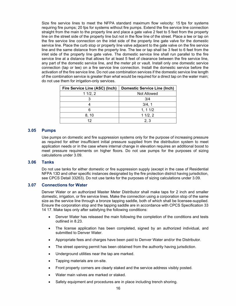
Size fire service lines to meet the NFPA standard maximum flow velocity: 15 fps for systems requiring fire pumps; 20 fps for systems without fire pumps. Extend the fire service line connection straight from the main to the property line and place a gate valve 2 feet to 5 feet from the property line on the street side of the property line but not in the flow line of the street. Place a tee or tap on the fire service line connection on the inlet side of the property line gate valve for the domestic service line. Place the curb stop or property line valve adjacent to the gate valve on the fire service line and the same distance from the property line. The tee or tap shall be 3 feet to 6 feet from the inlet side of the property line gate valve. The domestic service line shall run parallel to the fire service line at a distance that allows for at least 5 feet of clearance between the fire service line, any part of the domestic service line, and the meter pit or vault. Install only one domestic service connection (tap or tee) on a fire service line connection. Install the domestic service before the activation of the fire service line. Do not use combination services if the domestic service line length of the combination service is greater than what would be required for a direct tap on the water main; do not use them for irrigation-only services.
Fire Service Line (ASC) (Inch) Domestic Service Line (Inch) 1 1/2, 2 Not Allowed
3 3/4 4 3/4, 1 6 1, 1 1/2
8, 10 1 1/2, 2 12 2, 3
3.05 Pumps
Use pumps on domestic and fire suppression systems only for the purpose of increasing pressure as required for either insufficient initial pressure supplied from the distribution system to meet application needs or in the case where internal change in elevation requires an additional boost to meet pressure requirements on higher floors. Do not use pumps for the purposes of sizing calculations under 3.09.
3.06 Tanks Do not use tanks for either domestic or fire suppression supply (except in the case of Residential NFPA 13D and other specific instances designated by the fire protection district having jurisdiction, see CPCS Detail 33263). Do not use tanks for the purposes of sizing calculations under 3.09.
3.07 Connections for Water Denver Water or an authorized Master Meter Distributor shall make taps for 2 inch and smaller domestic, irrigation, or fire service lines. Make the connection using a corporation stop of the same size as the service line through a bronze tapping saddle, both of which shall be licensee-supplied. Ensure the corporation stop and the tapping saddle are in accordance with CPCS Specification 33 14 17. Make taps only after satisfying the following conditions:
• Denver Water has released the main following the completion of the conditions and tests outlined in 8.23.
• The license application has been completed, signed by an authorized individual, and submitted to Denver Water.
• Appropriate fees and charges have been paid to Denver Water and/or the Distributor.
• The street opening permit has been obtained from the authority having jurisdiction.
• Underground utilities near the tap are marked.
• Tapping materials are on-site.
• Front property corners are clearly staked and the service address visibly posted.
• Water main valves are marked or staked.
• Safety equipment and procedures are in place including trench shoring.
17
• The tapping location on the main is excavated and the water main surface is exposed and clean.
Make taps to the main for 3 inch and larger service lines with a tee connection or a tapping sleeve in accordance with the CPCS Specifications. Denver Water or a Contractor may install 3 inch and larger domestic service taps. For Denver Water installed connections, the Contractor shall excavate the ditch and around the water main on all sides. Denver Water will supply and install the tapping sleeve or cut-in tee at cost. The Contractor shall connect to the outlet, install the piping, set the valve boxes, and backfill the trench.
Exception: Contractors installing mains may install fire service lines and tee connections for domestic service lines if the connections are 3 inch and larger and the service line is installed with the main extension. Such an installation is subject to the proper release of tap application papers, the payment of appropriate fees, and the approval of the appropriate fire department, see 8.23 for the acceptance of mains.
Electrically insulate domestic service lines connected to metallic water mains with Denver Water approved insulating fittings or gaskets. Properly install corporation stops and provide enough slack in the service lines to protect against pullout. When tapping mains, dig out bedding material and apply two to three wraps of adhesive tape completely around the polyethylene-encased pipe to cover the area where the tapping saddle and machine will be mounted. After mounting the tapping machine, install the corporation stop directly through the tape and the polyethylene. After the tap is complete, inspect the entire area for damage and repair if necessary. Replace bedding material removed during excavation in kind and compact in accordance with CPCS Specification 31 23 33.
Multiple taps on the same side of the main shall be a minimum of 5 feet apart, measured longitudinally along the centerline of the main. Stagger multiple taps on opposite sides of the main by a minimum of 2 1/2 feet, measured longitudinally along the centerline of the main. Do not make taps within 3 feet of any main line pipe fitting.
3.08 Taps and Saddles Ensure taps and saddles meet the product and installation requirements of CPCS Specification 33 14 17. In Distributor Contract Areas, the Distributor shall have the option to perform the required operations to eliminate pressure in the pipeline being tapped. Denver Water will perform the operations inside Denver and Total Service Contract Areas. A fee per tap will be charged by Denver Water for performing the operations required to eliminate pressure in the PVC pipeline.
Ensure tapping saddles with a tap size of 2 inch and smaller for DI and AC pipe consist of a bronze body with two bronze straps. Ensure saddles for PVC pipe are single strap bronze saddle. Do not install taps on PVC pipe containing water under pressure. Ensure the tapping of dry mains only occurs on PVC pipe. Taps on AC, CI, or DI pipe may be tapped under pressure or wet.
3.09 Size Size taps and service lines to supply the property served while not being so large as to cause inaccuracies in metering low flows. The minimum size allowable for a service line is 3/4 inch or the minimum recommended size resulting from a fixture count document, completed by the PE, using an accredited fixture unit/count methodology or one standard diameter less than required by the fixture unit/count methodology adopted by the authority having jurisdiction for commercial and multi-family service line requests. For 13D residential multi-purpose piping systems the minimum allowable service line size is 1 inch. Ensure the tap, corporation stop, meter, and the portion of the service line between the corporation stop and 5 feet past the meter are the same size. The service line may only be increased one standard size to the next approved diameter beginning 5 feet downstream of the meter, including backflow prevention. This is allowed to satisfy maximum pressure loss criteria; it is not for achieving greater flow using a smaller tap.
Size taps and service lines to produce a water velocity no greater than 10 fps at peak demand as estimated by an accredited fixture unit/count methodology. Additionally, the total pressure drop in the service line from the main to the building shall not exceed 25 psi without backflow prevention or 35 psi and a minimum residual pressure of 20 psi at the building beyond any backflow prevention under peak domestic demand flow. The PE shall determine additional fire flow demand and service sizing and evaluate additional flow demands required to meet NFPA 13D or 13R and size the service lines accordingly.
18
For residential domestic service lines meeting NFPA 13D, ensure the tap, corporation stop, meter, and portion of the domestic service line between the corporation stop and 5 feet past the meter are the same size. The service line may only be increased one standard size to the next approved diameter beginning 5 feet downstream of the meter. The PE shall appropriately design the NFPA 13D fire sprinkler system. Ensure the tap, corporation stop, meter, and that portion of the service line between the corporation stop and the valve before the BFPA are the same size. The irrigation service line may be increased in size to the proper design size for the BFPA beginning at least 5 feet downstream of the meter pit or vault. Additional pipe increases are allowed after the BFPA to satisfy the maximum design water velocity in the irrigation system.
Design the fire service line in accordance with the building or fire code adopted by the authority having jurisdiction. Size the fire service line equal to or smaller than the main to be tapped. If redundant fire service lines are required, identically size them to meet the full demand and head loss specific to the fire protection system at each connection. Do not change size between the main and the fire system control equipment located inside the building.
To be considered for a manifold service line with individual meter pits in a staggered pattern or with shared access, the project site needs to be a common property with a HOA, party wall, or other agreement. Ensure the manifold tap, manifold service line, manifold corporation stop, and manifold trunk line are the same size. Do not use manifold service lines for irrigation service lines or fire service lines, including those that meet NFPA 13D and those that serve a common area. Downstream of the manifold, ensure the licensee-owned domestic service line is in accordance with 3.02. Ensure installation is in accordance with CPCS Detail 33267 or CPCS Detail 33268, using a combination of the two details is prohibited.
3.10 Pipe Material Pipe material is dependent on the size of the service line and shall extend from the tap to the first mechanical fitting inside the structure. Use seamless copper tube 3/4-inch service lines through 2-inch service lines in accordance with CPCS Specification 33 14 17. Use DI pipe for 3 inch and larger service lines in accordance with CPCS Specification 33 05 19.
3.11 Curb Stops, Valves, and Valve Boxes Install a curb stop or gate valve of the same size as the service line on the service line at a location in accordance with 3.02. The Meter Inspection Supervisor may authorize deviations to 1 inch and smaller curb stop installations. The PE shall request such deviations in writing.
Equip buried valves and curb stops with a CI valve box and large oval base. Use a roadway box when a 3/4 inch or 1-inch curb stop is placed in paved areas in accordance with CPCS Specification 33 14 17. Distributors may use compression fittings at the curb stop on 2 inch and smaller pipe by variance approval.
3.12 Meters Do not install meters until the proposed installation is approved, and Denver Water tests and numbers the meters. Ensure registers and associated AMR/AMI devices are fully compatible with the meter reading system in use where the meter is installed. The Meter Inspection Supervisor will determine the AMR/AMI system to be used.
Denver Water will inspect 3 inch and larger meter installations prior to backfilling and upon completion of the installation. Denver Water will inspect 2 inch and smaller meter installations after final grade is established at a minimum of 5 feet radially around the meter setting. Denver Water will install the AMR/AMI device at the time the meter installation is inspected at the expense of the Owner of the premises.
Ensure meters are the same size as the corporation stop or service tee and that portion of the service pipe between the meter and the corporation stop. Do not install a meter smaller than 3/4 inch unless it is to serve as a replacement for an existing meter of the same size. In cases where the full capacity of a previously used service pipe is not required, Denver Water may allow installation of a meter that is smaller than the service pipe provided the service pipe is reduced to the size of the meter for a distance of no less than ten times the larger pipe diameter on the inlet side of the meter, or 5 feet, whichever is longer.
19
3.13 Automatic Meter Reading and Automatic Metering Infrastructure Equipment Ensure meters, with the exception of those in Master Meter Contract Areas, are equipped with the AMR/AMI device determined by Denver Water and installed in accordance with Denver Water’s instructions in a place that allows for radio signal collection. Special metering and AMR/AMI systems may be required for services connected to water mains in easements.
Ensure the register of each meter is equipped with an AMR/AMI device, as directed by the Meter Inspector, and mounted in accordance with the CPCS Details. In most cases, the meter will be equipped with the latest model of Itron ERT. In special circumstances identified by the Meter Inspector, AMI or a remote AMR device may be required at a distance of up to 150 feet of wire length from the meter pit to the vault and mounted on the outside of the building, a post, or another structure. Run the signal wire (Belden #9451) for remote AMR device installations through 1-inch PVC conduit at a minimum.
For most installations on 1 inch and smaller meters, mount the AMR/AMI device through the CI meter pit lid or beneath the composite meter pit or vault lid. For most installations on 1 1/2 inch and larger meters, mount the device beneath the manhole lid. For some installations on 3 inch and larger meters, a remote AMR device with the signal cable in a conduit may be required. Denver Water will determine this on a case-by-case basis. The Meter Inspector will provide direction on the type and location of the device required during the mandatory pre-construction meeting for meter installations. One device is required for each meter register.
For existing meter installations of any size, there may be AMR device installations that are not in accordance with 3.14. Denver Water will make determinations to change the meter pit or vault lid and AMR device mounting at its discretion and cost. Such installations may incorporate adapters and special mounting equipment selected and approved by Denver Water.
Where inside meter settings are approved by the Meter Inspector in advance, in writing, install AMI or remote AMR devices on the outside of the building as directed by Denver Water. The licensee shall provide the approved signal cable in a conduit from the location of the meter to the mounting location of the AMR device; ensure the length of the signal cable does not exceed 150 feet.
Any meter setting that differs from the configuration shown on the CPCS Details, including inside meter settings, will need to be approved in writing by Denver Water’s Meter Inspector before construction. If it is necessary to obtain radio signals using drive-by equipment from a public street or via a meter-reading network, Denver Water may require the installation of a remote AMR device, radio repeater, network collector, and/or other special equipment or installation configuration installed at the licensee’s expense. Some meter-reading devices may require the licensee to provide a mounting location.
3.14 Outside Meter Setting Install the outside meter in an approved coppersetter or yoke with the inlet and outlet spuds in a horizontal position and housed in a concrete or approved composite meter pit or vault in accordance with the CPCS Details. Install coppersetters for 1 inch and smaller meters with meter spuds placed 18 inches below the meter pit lid to facilitate maintenance and replacement. Sit the meter horizontally with the meter register pointing up. Install larger meters in vaults in accordance with the CPCS Details. Deviations in installation height, spacing, pipe location, mounting supports, and other details shall be approved by the Meter Inspection Supervisor in advance, in writing.
3.15 Inside Meter Setting Do not use an inside meter setting on water service connections without the Meter Inspection Supervisor’s written approval prior to installation of the service connection at the main. The PE’s request shall include an explanation for its need, a site plan drawing to scale showing exact locations of the proposed water facilities with building footprints and paved areas, an indication of the means by which Denver Water will gain access to the meter during normal business hours, and a detailed, dimensioned plan and profile of the meter room that shows piping, equipment, and other water-related facilities, e.g., fire sprinkler controls and BFPAs.
20
An existing inside meter setting on a water service connection may remain if there are no changes made to the tap, service line, or meter setting. If the structure containing an inside meter is to be reconstructed, considerably remodeled, or the service line is to be reconstructed, relocated, or replaced, relocate the meter to an outside meter pit or vault.
An inside meter setting is for use with a 1 1/2 inch or larger meter where there is inadequate room for the proper installation of a meter vault after exhausting other reasonable alternatives. An inside setting will be allowed for industrial and commercial properties and multi-family premises where full-time, on-site management is provided and directly accessible from a public ROW. The licensee shall provide safe, unimpeded access during Denver Water’s normal working hours. Obtain the Meter Inspection Supervisor’s written approval to use an inside meter prior to tapping the water main. If the tap is already installed, obtain written approval prior to converting the stub-in to a service line. The Meter Inspection Supervisor, in consultation with the Meter Inspector, will assess and approve specific details of meter type, location, access requirements, AMR/AMI configuration, piping, valves, and other requirements on a case-by-case basis.
Install inside meter settings in accordance with the CAD drawing files detailed in Denver Water’s CAD Standards External Requirements and the following additional requirements:
• Ensure the total length of the service line, measured from the street main to the inlet valve of the meter, is 60 feet or less.
• Heat the space containing the meter to prevent the freezing of pipes and equipment, include a floor drain within 10 feet of the meter, and provide accessibility to Denver Water’s meter maintenance and meter reading employees during Denver Water’s normal working hours with minimal delay.
• Ensure the meter is adjacent to the point where the domestic service enters the building through the foundation wall with a minimum amount of exposed pipe before the meter.
• Bolt the meter in place in a flanged DI pipe system with a bolted sleeve-type coupling on the outlet side.
• Ensure the meter inlet and outlet and bypass have non-rising stem, clockwise opening gate valves mounted vertically. Ensure the bypass pipe is no higher than 6 feet above the floor and at least 2 1/2 feet above the meter; allow for at least 2 feet of clearance to the wall.
• Install a check valve 5 feet downstream of the meter when a backflow prevention device is not required.
• Ensure the top of the meter is higher than 40 inches above the floor.
• Install BFPAs, PRVs, and other components after the meter and downstream bypass tee. In most cases, 5 feet of pipe is required between the bypass tee and the first component.
• One or more indoor AMI devices or outdoor remote AMR devices are required for inside meter settings, the location will be determined during the review of the request.
3.16 Meter Bypass Lines A bypass line is required for 1 1/2 inch and larger meters except those used for irrigation-only service, whether installed in an outside or an inside setting. Ensure bypass lines contain an independent isolation valve and do not contain tees, plugs, or other outlets through which water could be withdrawn. Bypass lines may only be activated by Denver Water. Bypass lines for 1 1/2-inch meters and 2-inch meters shall be integral to the meter yoke with an appropriately sized ball valve. Connect bypass lines for 3 inch and larger meters to the main line at tees before and after the meter and include a gate valve with wheel operator. Lock bypass lines in the closed position when not in use.
3.17 Construction The Contractor shall be a plumber licensed by the authority having jurisdiction to perform work in the public ROW and have a current plumbing license to install service lines inside Denver, Total Service, and Read and Bill Contract Areas where work is to be performed.
21
3.18 Abandonment or Removal of Service Lines and Tap Cuts It may become necessary to remove or abandon a service line or a stub-in due to redevelopment and changes in water requirements for the premises, or to relocate a service line due to changes in the configuration of the premises. An abandoned or relocated service line shall have the tap cut at the main or fire service line to ensure that it cannot be used to remove water from the system. A Denver Water Inspector will witness service line tap cuts.
Make service line changes in accordance with Denver Water’s Operating Rules. Coordinate tap cuts through the Sales Administration Section. Water plans for 3 inch and larger taps are required for review and approval, see 2.04. Service lines shall be metered until disconnected from the main in the presence of a Denver Water Inspector.
For 2 inch and smaller service lines, excavate the service line connection where the corporation stop is inserted into the water main. The corporation stop shall be closed, the service tubing or piping removed from the corporation stop, the threads scarred on the corporation stop, and a section of the water service line at least 12 inches long cut out. Remove the curb or valve box over the curb stop in its entirety or cut it off at least 18 inches below the ground line. Remove the meter pit in its entirety, if present. If left in place, cut it off at least 18 inches below the ground line and fill it with sand or other fill material.
For 3 inch and larger service lines, excavate the service line connection over the service tee on the water main. Remove the valve at the main and plug the tee or tap. Remove the property line valve box or cut it off at least 18 inches below the ground line. Remove the meter pit in its entirety, if present. If left in place, cut it off at least 18 inches below the ground line and fill it with sand or other fill material.
Deliver removed meters to Denver Water’s Meter Shop for a final test and reading. Do not use the meters again in the Denver Water system.
Before demolishing a building with an inside meter setting, the licensee shall install a meter pit or vault with a new meter and AMR/AMI device in an outside setting or cut the tap in accordance with this Section. Coordinate either action through the Sales Administration Section prior to the demolition process.
3.19 Disinfection Requirements for Recycled Conversion Projects Cut off potable water taps and clean and disinfect new fittings in accordance with AWWA C651 with an NSF 60 certified sodium hypochlorite solution prior to installation using a swab or spray disinfection method. Cap the pipe with a permanent bulkhead/blind flange or a temporary pneumatic plug until the installation of a permanent cap. Prevent environmental contamination (e.g., ground water, storm water, animals, and insects) from entering the potable distribution system and/or service line.
For 3 inch and larger taps, clean and disinfect the exposed pipe and blind flange where the tap is cut. Denver Water will perform a directional flush (i.e., operate the valve) to remove chlorinated water via a hydrant and dechlorinate before discharging water into the environment.
Denver Water will collect physical parameter samples representative of the potable distribution system during the flushing process and notify its Inspector if passing results are attained. If attained, the existing potable service line will be released for service. If not attained, continue flushing and retesting until the appropriate results are reached.

22
Chapter 4: Easements and Licenses
4.01 Granting an Easement to Denver Water When an Owner/licensee is required to grant permanent easements to Denver Water prior to the installation of water mains, the Owner/licensee shall submit the items listed in Appendix B to the Sales Administration Section in one package with the first submittal of water plans. The easement plan review process will not begin until Denver Water receives the items.
Denver Water’s Property Management Section will prepare the easement agreement on a standard Denver Water form and return it to the Owner/licensee for the grantor’s signatures. The Property Management Section will prepare the documents for easements acquired on property inside Denver and Total Service Contract Areas. If the grantor knows of a potential change in property ownership at the time of the original easement submittal, the grantor shall communicate it to the Property Management Section. Failure to do so at the time of the original easement submittal may result in a duplicate document preparation fee. This fee may be charged for agreements that require more than one preparation of the easement agreement or if other significant modifications are required during preparation.
NOTE: The water main extension will not be authorized until Denver Water has accepted the easement, the easement agreement has been recorded, and any necessary documentation has been received, reviewed, and accepted.
4.02 Granting an Easement to a Distributor For developments located Outside Denver but inside a Distributor's Contract Area, the Owner/licensee shall submit a fully executed, recorded easement agreement on one of Denver Water’s approved distributor easement documents in hardcopy form prior to the approval of water plans. Interactive PDFs of the easement agreements may be obtained from www.denverwater.org. Do not prepare documents on forms other than the approved, preprinted easement document forms (i.e., Nonexclusive, Exclusive, PUD/PBG, or for those meeting the qualifications set by Denver Water, the Distributor Nonexclusive Performance Easement).
Along with the recorded document, submit a copy of the written legal description of the proposed easement area signed and sealed by a PLS. Legal descriptions that are not in compliance with the format and specifications of Appendix C are not acceptable. Submit a CAD drawing in accordance with Appendix C.
4.03 Acquiring an Easement from Denver Water When a utility company, municipality, or other entity requests the permanent or temporary construction right to use or cross Denver Water’s property or property interests, it shall provide the following:
• A letter to the Property Management Section requesting that Denver Water grant an easement. Ensure the letter includes the name of the entity to which the easement shall be granted and its intended use.
• Two copies of the written legal description of the easement area written in accordance with the format and specifications of Appendix C and signed and sealed by a PLS. Property descriptions that are not in compliance are not acceptable.
• A CAD drawing in accordance with Appendix C.
• Two copies of the overall site plan in accordance with Appendix C.
After the easement request has been conceptually approved, the requestor may be required to provide an appraisal of the easement area. The Property Management Section establishes the minimum cost for the granting of a permanent easement. Denver Water will prepare the documents and forward them to the grantor for signature. Construction will be authorized when a final easement is granted.
23
4.04 Obtaining a License to Use or Cross Denver Water Property When an applicant requests a revocable license for routine right-angle utility crossings of strip properties and Denver Water’s easements or for temporary uses when requesting permission to use or cross Denver Water’s property or property interests, the applicant shall provide a letter and application fee to the Property Management Section requesting permission to use or cross Denver Water’s property or property interests. Specify the intended use of the proposed license area, the method of installation, and which Denver Water property is affected. In addition, provide the legal name and contact information of the proposed licensee, sufficient detail to allow Denver Water to evaluate the request, the approval of which is at the discretion of the Property Management Section, the exact name of the company, corporation, partnership, etc. that shall own, operate, and maintain the proposed facilities and include the names and titles of the persons authorized to sign the agreement. Include the following enclosures:
• A CAD drawing in accordance with Appendix C based on a field survey prepared by a PLS. Submit the CAD drawing as a PDF and a DWG. If the proposed installation is crossing a waterline or the High Line Canal, include a profile in the CAD drawing.
• A check payable to Denver Water for the applicable, nonrefundable license fee sent with the letter of request. The fee for the use of Denver Water property, other than for a routine right-angle utility crossing, will be determined by the Property Management Section.
• Plans of the overall job in the area of the crossing, when available, and copies of new or proposed subdivisions whenever they would clarify or identify the location of the request.
• A copy of the engineered drawing that shows the proposed crossing detailing the method if installation. For projects that propose open cut construction, identify the crossing detail type in accordance with the CPCS Details. For projects that propose trenchless installation, provide a geotechnical investigation and supporting documents that detail the tunneling or bore method.
If the request is approved, the Property Management Section will prepare the license agreement on a standard Denver Water form and send it to the licensee for review and electronic signature via DocuSign. The licensee shall keep a copy of it on the jobsite. To request a temporary letter of authorization to access and use Denver Water’s property or property interests for a period of less than 1 year, submit the following to the Property Management Section: an application fee with sufficient site plans illustrating the proposed use area (links to Google Earth are not acceptable), a letter describing the proposed use of the property and the activities to be performed, and any equipment and/or vehicles to be used or staged on-site.
The temporary use of Denver Water’s property or property interests for longer than 1 year may require a license issued by Denver Water or alternative property rights agreements to be determined by Denver Water at its sole discretion.
24
Chapter 5: Distribution System Design and Layout
5.01 General Use the information presented in this Chapter for the design and layout of water distribution systems inside Denver and Distributor Contract Areas. Denver Water designed and built its system using conduits to supply water to its distribution systems. Using this framework, the individual customer receives water in sufficient volumes without excessive head loss.
The design and layout criterion presented herein applies solely to distribution systems. For design and layout criteria for transmission mains, see Chapter 9. For design and layout criteria for conduits, see Chapter 10.
5.02 Quality of the Distribution System Denver Water seeks to ensure the installation of proven high-quality materials using first class workmanship. Determination of the best materials and construction methods is based upon the lowest life-cycle costs. Sizing and layout are elements of the total consideration of the design, operation, and maintenance of a system that yields optimum service at the lowest consumer cost.
5.03 Size of Distribution Mains Size mains large enough to provide for domestic, irrigation, and fire protection flows to the area requesting service but not so large as to cause water quality issues. The maximum acceptable head loss for mains that are 6 inch, 8 inch, and 12 inch is 2 feet per 1,000 feet of main for the maximum hour flow using a C-value of 130; however, this does not apply under fire flow conditions. Size distribution mains for fire protection using maximum day flows and needed fire flow resulting in a minimum residual pressure of no less than 20 psi in the localized area of interest. Denver Water reserves the right to size mains to accommodate future needs.
Size new mains to be 6 inch, 8 inch, or 12 inch as determined by Denver Water. If approved in writing by Denver Water, 4-inch mains may be used in some cul-de-sacs without a fire hydrant. Denver Water does not allow dead-end mains in its integrated system; however, dead-end mains in cul-de-sacs will be evaluated to determine if the appropriate number of services exist to maintain water quality turnover.
Mains follow a standardized grid that is based upon the consideration and analysis of studies that use network simulation. This grid requires a 12-inch main every 1/2 mile with alternating 6 inch and 8-inch mains in the streets within the quarter section and a 6 inch or 8-inch main in the street at approximately the 1/16 line to eliminate 1/2 mile runs. For a typical grid layout, see the CPCS Details.
Because of the high fire risk and the minimal intersection of mains, PBGs are treated the same as industrial or business areas. In such areas, design mains to integrate and connect to adjacent parcels and existing systems to provide overall system integration. Do not use on-site bubble loops, which can contribute to water quality problems, unless another alternative is unavailable. In cases where there are no existing mains on undeveloped parcels next to new development, the addition of easements to provide future integration may be required. This requirement may also apply to residential development.
Denver Water evaluates site fire flows for multi-family and mixed-use developments with one side of the looped system out of service. This simulates a distribution system outage that would result in a worst-case scenario for the development. Denver Water will evaluate exceptions to looping at its discretion, such exceptions may need to meet additional requirements. Denver Water will analyze grid systems for developing areas to determine adequacy. Do not install parallel mains.
25
5.04 Fire Protection Systems The number and location of fire hydrants in each area is determined by the appropriate fire department. Install fire hydrants on the Northeast corner of street intersections; otherwise, install hydrants on property lot side lines that are extended to the street. Set the fire hydrant branch line at a 90-degree angle to the street main. Set the hydrant at the end of the branch line facing the branch line. Do not use horizontal bends, vertical bends, or reducers in the fire hydrant branch line unless approved in writing by Denver Water. Do not extend the fire hydrant branch line beyond the dedicated public ROW, easement, or property line by more than 25 feet as shown on the CPCS Details. Denver Water will review proposed fire hydrants requiring a full width easement; approval is at its discretion. Do not make any size or manner of tap on a fire hydrant branch line. Install isolation valves on the main between two fire hydrants.
Only one fire hydrant may be connected to a dead-end main in cases where looping is not an alternative, except as approved in writing by Denver Water or the Distributor. Avoid redundant hydrant installations and the unnecessarily high density of fire hydrants where existing hydrant function would be duplicated. Denver Water reviews these types of hydrant requests; approval is at its discretion. The review will be based on the number of fire hydrants in close proximity, hydraulic analysis, and correspondence with the appropriate fire department.
Fire service lines are connections made to existing mains that run to the property line and provide water for fire protection systems. Those who protect the structures served determine the size of fire service lines. Install the fire service line at a right angle to the distribution main and run it straight from the main to the property line. Do not install horizontal or vertical bends in the line; however, bends may be installed when making a wet tap where the tap location conflicts with an existing pipe joint or where interference prohibits a straight-line installation. Use such horizontal or vertical bends only when approved in writing by Denver Water.
Do not use multiple fire protection appurtenances, including any combination of fire hydrants and fire service lines for any single project site, on a dead-end main. Denver Water will give additional consideration in the case of single-family residential homes on a cul-de-sac where fire service lines are required. Install an approved USC FCCCHR BFPA on water service connections that supply a fire protection system.
5.05 Backflow Prevention and Cross-Connection Control Program Denver Water will protect its potable system from contamination due to backflow occurrences through residential, multi-family, irrigation, and/or commercial property water service connections (e.g., cross-connections) in accordance with CDPHE Regulation 11. Denver Water needs the cooperation of the public and licensees to ensure this responsibility is met. Denver Water may request access to a property or facility to conduct an on-site cross-connection control site survey audit. Denver Water requires the installation of a containment assembly on commercial property service lines. In high hazard applications, install a RP BFPA. In low hazard applications, install a DC BFPA at the discretion of Denver Water’s Cross Connection Control group. Failure to comply with installation and annual testing requirements may result in suspension of service or imposition of charges.
Ensure the BFPA is manufactured in accordance with AWWA C510 and C511 and meets USC FCCCHR specifications. Ensure components in contact with potable water are certified to be in compliance with NSF/ANSI 61 and NSF/ANSI 372. Requirements for approved USC FCCCHR BFPA installations based on the degree of hazard are outlined in Appendix D and shall be in accordance with CPCS Standard Details.
The licensee shall have a certified ABPA or ASSE tester inspect and test an existing or newly installed containment BFPA on dedicated and recycled water service lines upon installation and annually thereafter, if applicable. Conduct tests at the expense of the licensee. The licensee shall repair or replace BFPAs at its expense when found to be defective; keep records of tests, repairs, and replacements, and send a copy of the annual test to Denver Water. Installed BFPAs that do not meet the requirements outlined in Appendix D, but were approved assemblies at the time of installation, may remain if they have been properly maintained and pass annual testing. If the BFPA is replaced, ensure the replacement is USC FCCCHR approved.
26
The certified ABPA or ASSE tester shall do the following:
• Submit a copy of the official ABPA or ASSE certification to Denver Water’s Cross Connection Control group each time the certification is renewed.
• Submit a copy of the test kit calibration certification annually.
• Have a dedicated recycled water test gauge.
• Complete the BFPA test report and submit a copy of the containment BFPA report to Denver Water’s Cross Connection Control group within 5 days. Denver Water will not accept incomplete or illegible test reports. Supply test reports on Denver Water’s test form which can be obtained from www.denverwater.org.
• Indicate containment or containment by isolation on the test report. (CDPHE does not require the submission of isolation test results to Denver Water.)
• Indicate the type of usage (i.e., domestic, irrigation, fire, or recycled) on the test report.
• Confirm the Denver Water service address, meter number, BFPA serial number, size, manufacturer and model, location, and record the values on the test report.
• Contact Denver Water’s Cross Connection Control group for discrepancies regarding the meter or BFPA.
• Sign, date, and include the time of the test on the report.
• Submit required test reports to:
Denver Water Attn: Cross Connection Control 6100 W. Quincy Avenue Denver, CO 80235 Phone: 303-628-5969 Fax: 303-794-8325 Email: [email protected]
If the BFPA fails and cannot be repaired the same day, the certified ABPA or ASSE tester shall notify the Cross Connection Control group within 24 hours. The tester shall submit a copy of the failed test report to the Cross Connection Control group within 3 days. The licensee shall coordinate the necessary repairs to the BFPA and retest the unit within 15 days. The licensee shall submit a passing test report to the Cross Connection Control group. Failure to comply may result in the suspension of water service. If the premises has a high hazard BFPA and is deemed a threat to public health (via the private plumbing system), Denver Water may suspend the dedicated water service line immediately. The licensee shall repair or replace the BFPA before water service will be restored.
Single-family residential customers are exempt from Denver Water’s cross-connection control requirements unless the premise is served by a fire suppression system, a dual water supply, or other known hazards. Dual water supply conditions require a Dual Water Supply Agreement to be in effect between Denver Water and the Property Owner. The Property Owner agrees he or she shall not cause or allow the presence of any condition or uncontrolled connection, either actual or potential, at the premises documented on the agreement. The Property Owner shall, at his or her cost, install a USC FCCCHR BFPA on the domestic service line supplied to the premises and hire an ABPA or ASSE certified tester to test the assembly upon installation and annually thereafter. The Property Owner shall provide a copy of the test reports to Denver Water’s Cross Connection Control group.
For questions or concerns, contact Denver Water’s Cross Connection Control group by calling 303-628-5969 or emailing [email protected].
27
5.06 Operating Pressures within the Distribution System Pressures within the distribution system shall be a minimum of 40 psi during the maximum hour demand and have a maximum of 110 psi static pressure in the main. The maximum pressure fluctuation at any location in the distribution system between maximum hour demand and minimum hour demand shall not exceed 30 psi.
5.07 Pressure Regulating Valves Denver Water uses PRV installations to control pressure within its system. When main extension plans are submitted for review, the need for a PRV installation will be determined based on existing pressure zones and the existing system layout. Include PRV settings on plans with the elevation and the upstream and downstream hydraulic grade line and pressure. Denver Water will make pressure settings and field adjustments. Denver Water reserves the right to verify the settings on plans submitted in Distributor Contract Areas that require a PRV. Denver Water may own and maintain PRVs connected to its conduits as necessary. Denver Water may require and conduct monitoring of the PRV via SCADA equipment in certain situations identified by Distributor PRV agreements. Ensure the equipment used is of the manufacture and type specified or approved by Denver Water, see 5.14. Ensure District Ownership and Operations procedures are in accordance with Appendix E.
Design and install PRVs in accordance with Chapter 2. PRVs between Denver Water and a Distributor are classified as one of the following:
• Distributor owned, maintained, and operated: The operation of the PRV affects only the Distributor within which they are located, or has only a minimal potential for impact to Denver Water or a Total Service Contract Area.
• Denver Water owned, maintained, and operated: The operation of the PRV affects only the Denver Water or Total Service Contract Areas within which it is located, or the PRV is in a Distributor area but has a greater impact to Denver or Total Service Contract Areas.
• Distributor owned and maintained with cooperative operations: The PRV is located within the Distributor Contract Area but through interconnects to Denver or Total Service Contract Areas resulting in a larger impact to Denver and Total Service customers. The Distributor will own, maintain, and operate the PRV while the downstream pressure setting will cooperatively be determined by Denver Water and the Distributor that integrates the distributor’s operation into the overall operation of Denver Water’s system.
The downstream pressure setting for PRVs can have direct effects on the operation of the transmission and distribution systems of Denver Water and its Distributors. Operational priority is as follows:
• Priority 1: Primary supplies set to a downstream operating pressure equivalent to the nominal static hydraulic gradient for the pressure zone being fed; operate continuously.
• Priority 2: Secondary supplies set to a downstream pressure equivalent to 5 psi below the nominal static hydraulic gradient for the pressure zone being fed; operate under higher demand conditions.
• Priority 3: Tertiary supplies set to a downstream pressure equivalent to 10 psi below the nominal static hydraulic gradient for the pressure zone being fed; operate under emergency and fire flow conditions.
5.08 Storage Facilities Water storage facilities are allowed for the storing of water from Denver Water's system where authorized and approved in writing by Denver Water. Built in provisions for draining, access, inspecting, and cleaning are required, including a suitable source of water. The cleaning and drainage of storage facilities will be subject to Denver Water’s approval. The installation of SCADA equipment for storage facilities of the type specified by Denver Water may be required, see 5.14.
28
5.09 Electric Pump Motors Ensure electric pump motors meet the requirements of the CPCS Specifications, including the following:
• Polyphase squirrel-cage rotor induction with adequate starting and running torque sufficient to meet the electrical and operating conditions of the installation.
• In accordance with these Standards and subject to Denver Water approval.
• Sizing does not make use of the service factor.
• Rated for direct across-the-line, full voltage starting.
• Controlled by a motor starter which employs a method of starting consistent with the requirements of the electric power utility, the plant power system, and the consideration of extended motor life, reliability, and acceptable voltage drop during starting.
• Designed and constructed to operate without damage in reverse rotation at the maximum speed obtainable with the connected pump acting as a turbine under the conditions given by the approved hydraulic system design.
• Equal to or exceeding efficiency values in accordance with NEMA MG 1, Part 12.60.
• Starters equipped with motor protective devices in the form of overload relays, phase reversal, phase loss and under-voltage relay trips, ground fault detection, motor winding and bearing over-temperature alarm and trip, and any other such functions as may be required by Denver Water for a particular installation.
• Installations maintain an overall electrical system power factor between 0.9 lagging and 1.0 (unity) under normal operating load. If necessary, each motor equipped with power factor correcting capacitors as required to meet this standard.
5.10 Pumping Facilities Pumping facilities are allowed on mains or services supplying water from Denver Water's system only where authorized by Denver Water. Denver Water will prohibit the installation of pumping facilities where such installations would be injurious to the operation, or future operation, of its system. This requirement is not applicable to individual building fire sprinkler system pumps, domestic system boosters required in high-rise buildings, or irrigation system pressure boosting. Such applications require backflow prevention to eliminate the possibility of pumping into Denver Water’s distribution system. Ensure materials, equipment, and construction are in accordance with applicable codes and standards and approved by Denver Water. Denver Water requires that pump stations receiving water from its system meet the general design criteria outlined in Appendix F.
5.11 Distribution System Layout Install mains in dedicated public streets of the width defined herein. Ensure the main layout is of such grade, alignment, curvature, and other characteristics as to allow installation and maintenance in the usual manner. If Denver Water determines it is not feasible to make an installation in a dedicated street, make it in a Denver Water or Distributor easement. Denver Water will determine the conditions under which such an exception is allowed on a case-by-case basis. Only easements in accordance with the terms of Denver Water's standard easement form and these Standards will be accepted. The easement requirements defined shall be complied with prior to the acceptance of any existing system for Total Service Contract Areas. Easements granted for water mains near the perimeter of a lot or property line shall abut them to provide for future domestic and/or fire protection service from the water main to the adjoining lot or property, except as approved in writing by Denver Water.
29
Ensure the main alignment is parallel to dedicated ROW or easement lines. Normal practice is to lay the main on the north or east side of the street 5 feet or 10 feet from its centerline. In cases where the main alignment is within an established public or private roadway, install the main between the limits of the curb and gutter pan, the roadside drainage ways, or other such roadway limits, except as authorized by Denver Water. In addition, ensure there is a minimum of 10 feet from any edge of the dedicated ROW or easement to the centerline of transmission and distribution mains and a minimum of 15 feet for conduits, except as approved in writing by Denver Water.
The cross-section of a dedicated public ROW shall meet the minimum requirements of a 28 foot surfaced roadway, flow line to flow line, with an additional 2 1/2 feet on each side.
Ensure easement width requirements meet the following criteria:
• Private roadways with an island median: Roadways designed with islands at the entrances to developments shall have easements that extend across the entire roadway with the island located in the middle. Install the water line on the side of the island that is at least 20 feet wide from back of curb to back of curb. Confine other utilities to the opposite side of the island.
• Private roadways: The easement shall have a minimum width of 30 feet. Denver Water or the Distributor shall have exclusive use of 20 feet thereof, except for right angle utility crossings. Ensure the cross-section of a private roadway meets one of the following criteria:
A minimum of 26 feet of surfaced roadway with a 4 foot wide attached sidewalk making a total of 30 feet of surfaced area from back of curb to back of sidewalk in accordance with the CPCS Details.
A minimum of 29 feet of surfaced roadway with 6 inch wide concrete curbs making a total of 30 feet of surfaced area from back of curb to back of curb in accordance with the CPCS Details.
A minimum of 30 feet of surfaced roadway with permanent delineation on each side, the type, material, and location of which needs to be preapproved by the Property Management Section as a part of the plan review process and where neither cross-section on the CPCS Details is practical.
An easement in accordance with the terms of Denver Water’s Standard PUD/PBG form needs to be granted to Denver Water.
• Undeveloped areas: An exclusive easement shall have a minimum width of 30 feet. A nonexclusive easement shall have a minimum width of 50 feet.
Do not install or replace a water main in an alley.
Install fire hydrants within dedicated streets or in easements as previously defined. When Denver Water determines it is not feasible for a hydrant to be installed in this manner, install it in an easement adjacent to the street. The fire hydrant easement shall have a minimum width of 10 feet when the length of the easement is 25 feet or less. Ensure fire hydrant easements have a minimum width of 30 feet when the length of the easement is greater than 25 feet. The easement shall extend a minimum of 5 feet beyond the center of the hydrant in accordance with the CPCS Details. Install fire hydrants only at locations authorized by the appropriate fire department.
5.12 Isolation Valves Denver Water requires isolation valves every 600 feet in distribution systems that receive water from its system. Where blocks exceed 600 feet in length, or if two or more hydrants connect to the same main, additional isolation valves are required. Street intersections that carry heavy traffic or that contain major water distribution mains in both directions, as determined by Denver Water, require four valves, one on each extended property line. For a succession of short blocks that are perpendicular to the direction of a major feed and without residential services, several intersections may have the valve omitted in that direction but need to retain the 600 feet interval requirement. Denver Water requires an isolation valve between fire hydrants.
30
5.13 Connections to Conduits Denver Water will install connections to conduits that it owns or controls unless it authorizes otherwise. Denver Water will provide and install, at cost, fabricated pipe, tapping saddles, valves, etc. that are necessary to construct the connection.
5.14 Supervisory Control and Data Acquisition Design, install, and maintain the SCADA system used by Denver Water to monitor, control, and coordinate the operations of the water system or the operations between a Distributor’s water system and Denver Water’s system in accordance with Appendix G.
5.15 Interconnects with Other Water Systems Denver Water will only allow interconnections between its potable system and another Denver Water approved system in accordance with its Operating Rules. The design and installation of interconnections shall comply with Denver Water's plan review process.
Emergency facilities: Where the location of an interconnection within the service area is identified, it shall be included in a written agreement between Denver Water and the other parties to the interconnection, and such facilities shall be constructed in accordance with the Denver Water approved plans. Such facilities normally consist of one or more lines that are a minimum of 6 inch diameter, each consisting of a meter and associated piping as detailed on the submitted plans. Do not include a bypass line. A BFPA is required on unidirectional interconnections between Denver Water's potable system and another Denver Water approved system. A removable spool piece is required on bidirectional interconnections between Denver Water's potable system and another Denver Water approved system.
Where the location of an interconnection within the service area between Distributors is identified, it shall be included in a written agreement between Denver Water and the Denver Water Distributors; such facilities shall be constructed in accordance with Denver Water approved plans. Such facilities normally consist of one or more lines that are a minimum of 6 inch diameter, each consisting of a meter and associated piping as detailed on the submitted plans. Do not include a bypass line. At the sole discretion of Denver Water, a BFPA shall be installed at the Distributor’s master meter points of connection(s) in accordance with 5.05 and Appendix E.
Where emergency conditions require the use of temporary connections between fire hydrants to serve Denver’s water into another system, such installation shall be in accordance with the CPCS Details.
5.16 Flow Measurement Denver Water may require pitot installations for future flow measurement. If a pitot is required, a corporation stop shall be installed in accordance with the CPCS Details so that a pitot installation may be completed in the future.

INTENTIONALLY BLANK

31
Chapter 6: Materials
6.01 General Ensure materials are new, undamaged, the latest standard product of a manufacturer regularly engaged in manufacturing the product for at least 5 years, and in accordance with applicable CPCS Specifications. Ensure everything necessary to complete installations in accordance with these Standards is furnished and installed, including items not shown on plans and items included in applicable CPCS Specifications. Ensure installations are finished as fully operable, functioning parts of the Denver Water system.
Provide the materials necessary for installation when mains are extended. Acceptance of the materials or the waiver of an associated inspection in no way relieves the Contractor from the responsibility of furnishing materials that meet the requirements of the CPCS Specifications. The Board may reject materials that do not meet these requirements or that are damaged and return them to the Contractor at the Contractor's expense. Denver Water does not allow the use of manufacturers or models not approved in the CPCS Specifications.
New water industry products or materials will be tested if the Director of Engineering – Projects believes a product or material has merit. Denver Water will establish the criteria for the testing and evaluation of products and reserves the right to accept or reject any product or material regardless of test results, see Appendix H. If any approved manufacturer material fails to meet applicable CPCS Specifications and test criteria, the Board, at its discretion, may promptly remove the manufacturer and the model from the CPCS Specification’s Approved Manufacturer’s list and return the material to the supplier at the manufacturer’s and the supplier’s expense.
6.02 Size of Mains Size mains in accordance with 5.03.
Standard acceptable nominal diameters of distribution mains are 4 inch, 6 inch, 8 inch, and 12 inch. Standard acceptable nominal diameters of transmission mains are 16 inch and 20 inch. Standard acceptable nominal diameters for conduits are 24 inch and larger.
6.03 Pipe Classes Denver Water has established minimum design safety factors for system piping considering working pressures of 150 psi concurrent with a water hammer surge pressure of 110 psi for 4 inch, 6 inch, 8 inch, 12 inch, and 16 inch, and 70 psi for 20 inch and larger. Based upon these considerations, the following minimum AWWA standard pressure classes for acceptable types of pipe are required:
DI Special Thickness Class 50 6 inch, 8 inch, *10 inch, 12 inch, 16 inch, 20 inch
Special Thickness Class 51 *3 inch, *4 inch
Special Thickness Class 52 Carrier Pipe inside Casing Pipe
*Allowed for service lines only
PVC C900 DR 14 4 inch
C900 DR 18 6 inch, 8 inch, 12 inch, 16 inch, 20 inch
6.04 Selection of Pipe In general, the selection of the type of pipe (DI or PVC) is at the discretion of the PE in charge of the design. However, Denver Water reserves the right to deny the use of certain types of materials in specific circumstances. Where joint restraint is required, the designer shall select a pipe along with an approved system of restraint. Use corrosion protection systems when installing metallic pipe and fittings in corrosive soil areas, see 6.28.
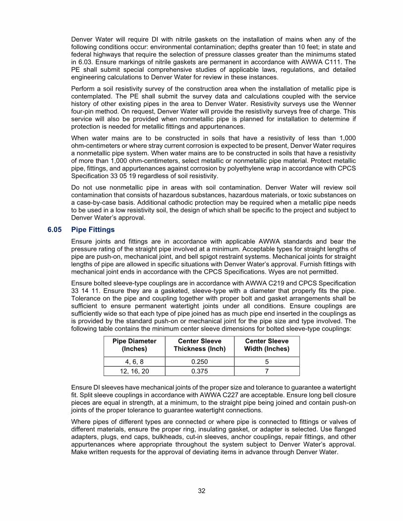
32
Denver Water will require DI with nitrile gaskets on the installation of mains when any of the following conditions occur: environmental contamination; depths greater than 10 feet; in state and federal highways that require the selection of pressure classes greater than the minimums stated in 6.03. Ensure markings of nitrile gaskets are permanent in accordance with AWWA C111. The PE shall submit special comprehensive studies of applicable laws, regulations, and detailed engineering calculations to Denver Water for review in these instances.
Perform a soil resistivity survey of the construction area when the installation of metallic pipe is contemplated. The PE shall submit the survey data and calculations coupled with the service history of other existing pipes in the area to Denver Water. Resistivity surveys use the Wenner four-pin method. On request, Denver Water will provide the resistivity surveys free of charge. This service will also be provided when nonmetallic pipe is planned for installation to determine if protection is needed for metallic fittings and appurtenances.
When water mains are to be constructed in soils that have a resistivity of less than 1,000 ohm-centimeters or where stray current corrosion is expected to be present, Denver Water requires a nonmetallic pipe system. When water mains are to be constructed in soils that have a resistivity of more than 1,000 ohm-centimeters, select metallic or nonmetallic pipe material. Protect metallic pipe, fittings, and appurtenances against corrosion by polyethylene wrap in accordance with CPCS Specification 33 05 19 regardless of soil resistivity.
Do not use nonmetallic pipe in areas with soil contamination. Denver Water will review soil contamination that consists of hazardous substances, hazardous materials, or toxic substances on a case-by-case basis. Additional cathodic protection may be required when a metallic pipe needs to be used in a low resistivity soil, the design of which shall be specific to the project and subject to Denver Water’s approval.
6.05 Pipe Fittings Ensure joints and fittings are in accordance with applicable AWWA standards and bear the pressure rating of the straight pipe involved at a minimum. Acceptable types for straight lengths of pipe are push-on, mechanical joint, and bell spigot restraint systems. Mechanical joints for straight lengths of pipe are allowed in specific situations with Denver Water’s approval. Furnish fittings with mechanical joint ends in accordance with the CPCS Specifications. Wyes are not permitted.
Ensure bolted sleeve-type couplings are in accordance with AWWA C219 and CPCS Specification 33 14 11. Ensure they are a gasketed, sleeve-type with a diameter that properly fits the pipe. Tolerance on the pipe and coupling together with proper bolt and gasket arrangements shall be sufficient to ensure permanent watertight joints under all conditions. Ensure couplings are sufficiently wide so that each type of pipe joined has as much pipe end inserted in the couplings as is provided by the standard push-on or mechanical joint for the pipe size and type involved. The following table contains the minimum center sleeve dimensions for bolted sleeve-type couplings:
Pipe Diameter (Inches)
Center Sleeve Thickness (Inch)
Center Sleeve Width (Inches)
4, 6, 8 0.250
5 12, 16, 20 0.375
7
Ensure DI sleeves have mechanical joints of the proper size and tolerance to guarantee a watertight fit. Split sleeve couplings in accordance with AWWA C227 are acceptable. Ensure long bell closure pieces are equal in strength, at a minimum, to the straight pipe being joined and contain push-on joints of the proper tolerance to guarantee watertight connections.
Where pipes of different types are connected or where pipe is connected to fittings or valves of different materials, ensure the proper ring, insulating gasket, or adapter is selected. Use flanged adapters, plugs, end caps, bulkheads, cut-in sleeves, anchor couplings, repair fittings, and other appurtenances where appropriate throughout the system subject to Denver Water’s approval. Make written requests for the approval of deviating items in advance through Denver Water.

33
Accomplish the harnessing of joints using one of the mechanical joint restraint systems specified in the CPCS Specifications or using one of the several proprietary joint restraint systems supplied by pipe manufacturers. Proprietary systems will require Denver Water’s approval prior to use. Regardless of the system used, restrained lengths of pipe for various fittings where harnessing is used or required shall be at least equal to the lengths in accordance with the CPCS Specifications and Details. Where joint restraint is required on PVC pipe, the designer may use a joint restraint system of the type supplied by pipe manufacturers and approved by Denver Water or switch to a metallic pipe. Do not use rods and clamps on PVC pipe.
6.06 Isolation Valves Ensure isolation valves are resilient seat gate valves as specified in CPCS Specification 33 14 19, are the same size as the main, and open clockwise, except as provided in Chapter 11. Do not use valves with operators that open counter-clockwise unless they are required by, or approval is obtained from, Denver Water.
6.07 Pressure Regulating Valves PRVs are used to keep downstream pressure uniform and less than that in the upstream main. Ensure PRVs are in accordance with CPCS Specification 33 12 33 and sized so that the velocity through the valve at maximum demand does not exceed 25 fps. If a wide range of flow rates is anticipated, more than one valve may be required. Ensure an adequate pressure differential across the valve under all ranges of flow to accomplish hydraulic throttling. When pressure differentials greater than 45 psi are expected or when the downstream pressure is low relative to the differential, special valve materials or a special valve design may be required.
Properly support PRVs and ensure adequate clearance above and below the valve to facilitate servicing. Use a manual bypass for single valve installations. Telemetering of data may be required. Install a gate valve on both sides of each PRV for isolation purposes. Ensure the general arrangement is in accordance with the CPCS Specifications and Details.
6.08 Tapping Valves and Sleeves Use tapping valves and sleeves concurrently to tap an existing main without interrupting service. Tapping valves do not replace property line valves; however, property line valves may not be needed if the out-distance of the main is 15 feet or less. Install valve boxes with tapping valves.
Make 2 inch and smaller taps by a corporation stop the same size as the service line. Make 3 inch and larger taps with an existing tee (cutting a tee into a dewatered line if allowed by Denver Water) or a tapping sleeve and a tapping valve. Select sleeves and gaskets properly sized to fit the type and class of pipe to be tapped. Where 3 inch and larger tapping sleeves are used, place a thrust block behind the tapping sleeve to prevent possible damage to the main from pressure shocks that develop as valves are first opened. Ensure tapping sleeves are in accordance with CPCS Specification 33 14 17 and thrust blocks are in accordance with the CPCS Specifications and Details.
6.09 Check Valves Check valves allow flow in one direction only; they close when the flow stops so reversal cannot occur. Ensure check valves are in accordance with CPCS Specification 33 14 19. They are required for 1 1/2 inch and larger meter installations where there is no BFPA downstream and at the Distributor’s master meter locations. Check valves are not a substitute for BFPAs; however, they may be omitted from the meter installation when a BFPA is within 150 feet of the meter.
6.10 Stop and Waste Valves Service lines require stop and waste valves on the service line inside the residence (near where the line enters the residence). Ensure stop and waste valves are in accordance with CPCS Specification 33 14 17 and have a drain plug located on the valve body so that when the valve is shut off the drain plug can be removed and the water above the valve drained out. For typical locations, see the CPCS Specifications and Details.
34
6.11 Valve Boxes Provide buried gate valves with a 6-inch CI valve box and large oval base. Ensure the valve box is of a design that will not transmit shock or stress to the valve, that it has the capability to be raised to the ground line, and is in accordance with CPCS Specification 33 14 11. The top section of the valve box shall be acceptable for use with a butterfly valve in accordance with CPCS Specification 33 14 11.
6.12 Valve Reference Marker Posts When valves are installed where adequate physical reference points are not available, as determined by Denver Water, valve reference marker posts may be required. Ensure valve reference marker posts are in accordance with the CPCS Specifications and Details.
6.13 Water Meters Ensure water meters are preapproved in accordance with the approved manufacturer and model. Denver Water will determine the type of meter to be installed at the time of the application based upon size, service requirements, location, and other conditions that may exist. Denver Water may change the type of meter at any time based on the water usage patterns of the licensee.
Ensure displacement meters, 3/4 inch through 2 inch, are in accordance with CPCS Specification 33 19 13. Known as nutating-disc or oscillating piston meters, they are positive in action. The pistons and discs displace or carry over a fixed quantity of water for each nutation or oscillation when operated under positive pressure. Displacement meters are generally used for residential, industrial, commercial, and irrigation applications requiring a 2 inch or smaller service. Furnish the 1 inch and smaller magnetic drive displacement type meter with a CI frost bottom.
Compound meters consist of two meters in a single case, one to measure small flows and the other to measure large flows. Compound meters are designed for the small meter to operate during low flows. As flows begin to increase, the large meter takes over. When the large meter is in operation, the small meter may or may not be in operation. Compound meters are generally used for residential, industrial, and commercial applications requiring a service larger than 3 inch, except for irrigation and certain industrial uses where flow rates are relatively constant. Compound meters are used for applications where domestic use is provided; ensure meters are in accordance with CPCS Specification 33 19 13.
Turbine meters measure primarily large, constant flows. Do not use turbine meters where possibilities of small flows exist below the manufacturer's stated minimum or for domestic use. Use turbine meters for irrigation applications requiring a 2 inch and larger service for certain industrial applications with relatively constant, high flows. Ensure turbine meters are in accordance with CPCS Specification 33 19 13, 3 inch and larger meters have a flanged in-line basket strainer installed on the upstream side, and meters smaller than 3 inch include an integral stainless steel strainer with a removable top plate.
Use fire service type meters, i.e., specialized types of compound meters, on any service that includes fire sprinklers, fire hydrants, or other fire protection behind the meter and in other cases as determined by Denver Water. Fire service type meters are required to meet specialized standards of UL, Factory Mutual, and other certifying agencies; ensure meters are in accordance with CPCS Specification 33 19 13. Single-family residences and duplexes with a limited number of sprinkler heads may be exempt from this requirement.
6.14 Meter Appurtenances Valves for 2 inch and smaller meters depend on the size and type of setting outlined herein, in accordance with AWWA C800 and CPCS Specification 33 14 17. Install a curb stop or valve the same size as the tap and the service line as close behind the curb line as possible.
• For 1 inch and smaller outside settings, install a curb stop 2 feet to 5 feet before the meter pit. Ensure the meter setting includes an angle valve or ball valve on the inlet side of the meter.
35
• For 1 1/2 inch and 2 inch outside settings, install a curb stop 2 feet to 5 feet before the meter vault. Ensure the meter setting includes angle valves or ball valves on the inlet and the outlet sides of the meter and the bypass line has a ball valve that may be locked in the closed position.
• For 1 inch and smaller inside settings, new meter settings are not allowed. Existing services are required to have a curb stop near the front property line, usually behind the curb, a stop and waste valve installed between the service line point-of-entry and the indoor meter setting, and a gate valve downstream of the meter.
• For 1 1/2 inch and larger inside settings, new meter settings are allowed with the written approval of Denver Water’s Meter Inspection Supervisor. Install a curb stop 2 feet to 5 feet from the property line. Existing services are required to have a curb stop near the front property line, usually behind the curb. Ensure services have coppersetters on the meter and the bypass line has a ball valve that may be locked in the closed position.
Use 3 inch and larger gate valves, in accordance with CPCS Specification 33 14 19, with DI service pipe. Support gate valves for use with meters in vaults and inside buildings by adjustable steel valve supports in accordance with the CPCS Specifications and Details, see 3.12.
A coppersetter is a metal pipe frame inserted in the copper service line piping to support and convey water to the meter. Ensure coppersetters are in accordance with CPCS Specification 33 14 17, that coppersetters for 1 inch and smaller meters include a lockable angle valve on the meter inlet, and coppersetters for 1 1/2 inch and 2-inch meters include lockable angle valves or ball valves on the meter inlet and outlet and a lockable ball valve on the bypass.
Ensure meter supports are solid concrete block in accordance with the CPCS Specifications and Details. Support 3 inch and larger valves with fabricated metal supports or jack stands in accordance with the CPCS Specifications and Details.
To ensure safety, meter settings shall provide for electrical continuity in the event the meter is removed from the setting. For 2 inch and smaller meters this is normally accomplished by installing the meter in a coppersetter that provides a continuous electrical path from the metallic piping on the downstream side of the meter setting to the metallic piping on the upstream side. Ensure there is an electrical continuity wire or strap connecting the pipe on either side of the meter setting in accordance with the CPCS Specifications and Details. Ensure the wire is copper with fittings suitable for bonding jumper and water pipe material. Install the meter setting in compliance with the NEC.
6.15 Meter Pits and Lids for 3/4 Inch and 1-Inch Meters Install meter settings for 3/4 inch and 1-inch meters in meter pits with a 24 inch nominal diameter and a total depth of 52 inches minimum from grade. Ensure the pit consists of a 24 inch nominal diameter by 48 inch high cylinder of concrete or composite with a dome or bell housing holding an internal frost lid and a locking top lid and the base unit is in accordance with CPCS Specification 33 14 17.
Construct concrete rings in accordance with CPCS Specification 33 05 61 and in compliance with ASTM C 478. Ensure meter pits are in compliance with CPCS Specification 33 14 17. Ensure units meet the requirements for composite meter pits in CPCS Specification 33 14 17. Install the pit plumb and at sufficient depth for the top of the dome to sit at or up to 1 inch below ground line. Use grade adjustment rings from the same manufacturer to raise the top of the pit or to accommodate the plumb pit to an angled ground surface.
36
Mount a CI dome or bell housing on the top of the pit that includes a support for an interior frost lid and a rim for locking the meter pit cover. Do not use composite and plastic domes, see CPCS Specification 33 14 17. Construct the cap-type meter pit top lid of CI or an approved composite material. Ensure lids are of the cap-type with a locking screw and bolt that provides a tight locking of the cover to the dome or bell housing of the meter pit, see CPCS Specification 33 14 17. Lids shall withstand AASHTO HS 20 highway loading plus 25% impact not to exceed 20,000 lbs. Ensure composite lids are available in various colors, as required by Denver Water, and have Denver Water Meter imprinted on the lid. When set in place of the dome, set the top of the meter pit lid at ground line. Ensure the inner frost lid is high-density polyethylene in accordance with CPCS Specification 33 14 17.
6.16 Meter Vaults for 1 1/2 Inch and Larger Meters Use precast concrete meter vaults from approved manufacturers in accordance with CPCS Specification 33 05 61. Use cast-in-place vaults in special circumstances with written approval of the structural design by Denver Water’s variance process. Design precast vaults so that joints and corners are waterproof. Make the roof and the walls of precast and cast-in-place vaults waterproof after construction using sealants, membranes, or other approved methods. Adjust access manholes to be flush with the finished landscape grade or surrounding pavement.
Circular vaults for 1 1/2 inch and 2-inch meters shall be 48 inch diameter and of sufficient depth to extend below the 4 1/2 feet to 6 feet depth below ground line of the service line. The wall thickness shall be at least 6 inches. Ensure the vault has a flat top with concrete grade rings supporting the manhole ring and 24 inch diameter manhole cover at ground line. When subject to traffic loads, vaults shall sit on reinforced concrete manhole beams and be in accordance with 6.19, 6.20, and CPCS Specification 33 05 61.
Rectangular vaults for 3 inch and larger meters shall be of a size and configuration in accordance with CPCS Specification 33 05 61 and approved by the Meter Inspector. Use precast concrete vaults from an approved manufacturer. Design vaults to support the street fill and HS 20 traffic loading in accordance with AASHTO Standards.
Ensure meter vault lids are ASTM A 48 Class 35B CI manhole covers with a 24-inch lid set into a 36 inch outer diameter ring. The manhole lid shall be solid with one 2 inch hole for turbine or displacement meters and two 2 inch holes for compound meters to accommodate AMR/AMI devices specified by Denver Water or be of a composite material meeting the requirements of 6.19.
Mount AMR/AMI devices through the CI manhole lid or outer ring, inside the vault with a composite cover, in a remote location on the side of a building, or on a pole, as directed by the Meter Inspector. Ensure meter vaults include copolymer manhole steps cast into the side of the vault evenly spaced at 12 inch centers, maximum.
6.17 Concrete Structures Design structures to support applicable loads. Submit design calculations, drawings, and contract specifications to Denver Water for review. Use Class A concrete, see 8.16 and CPCS Specification 03 30 00.
6.18 Steel Reinforcement for Concrete Steel reinforcement shall be deformed bars or welded steel fabric and in accordance with CPCS Specification 03 21 00.
6.19 Manholes Ensure manholes and reducing sections are precast concrete in accordance with CPCS Specification 33 05 61. Use manhole rings and covers in accordance with CPCS Specification 33 05 61 with the following additional requirements:
• The 24-inch manhole rings and covers shall be City of Denver, Colorado Standard pattern and constructed of CI or an approved composite material.
• The 24-inch CI manhole cover shall weigh approximately 165 lbs. The 24-inch CI ring shall weigh approximately 240 lbs.
37
• The 24-inch recessed manhole covers for meter vaults shall be CI Denver Water Standard pattern with one or two 2 inch holes for the mounting of an AMR/AMI device through the lid. Cast the lid with the words Denver Water Meter on the top.
• The 36-inch cover shall have an auxiliary 24 inch opening and cover. The 36-inch cover weighs approximately 250 lbs. The CI 36-inch ring weighs approximately 280 lbs.
• Construct composite manhole covers for meter vaults of fiber-reinforced polymer, furnished with a locking mechanism that prevents the lid from popping from its frame under traffic conditions, and cast with the words Denver Water Meter on the top. Ensure composite covers maintain AASHTO H 20 highway load rating and other performance characteristics between -60ºF and 160ºF, meet or exceed the requirements for CI manhole covers, and fit equally well in CI or composite frames. Composite covers shall be available in a variety of colors, as specified by Denver Water, and weigh less than 50 lbs.
6.20 Manhole Base Slabs and Base Beams Construct manhole base beams of precast, reinforced concrete in accordance with CPCS Specification 33 05 61. Ensure concrete is in accordance with CPCS Specification 03 30 00 and concrete reinforcement is in accordance with CPCS Specification 03 21 00.
6.21 Sump Pits for Vaults and Manholes Sumps are required for vaults and manholes where there is seepage into existing vaults, in PRV installations, and as determined by Denver Water. Use a gravity drain line or sump pump in conjunction with a sump where telemetry equipment is to be installed, ensure compliance with the CPCS Specifications and Details. Do not use a sump pump in a meter vault.
Normal practice in constructing a sump is to excavate a 30 inch diameter hole roughly 3 feet deep. A 6-inch concrete floor is placed and allowed to set. A 24 inch section of cardboard tubing is then used for an inside form with concrete poured behind it to approximately 3 inches of thickness. The CPCS Specifications and Details show a sump as part of a typical PRV installation. A cast-in-place floor shall incorporate a monolithic sump pit.
6.22 Vent Pipes Vent pipes are used in vaults and pits to provide proper ventilation. Installations that contain electrical equipment shall have a locally controlled, power-operated blower attached to the vent system. Do not use electric powered blowers in meter vaults. Field locate vent pipes at the nearest intersection of the street property line and the side lot line. Ensure vent pipe installation is in accordance with the CPCS Specifications and Details.
The above ground industrial vent pipe shall be 6 inch nominal diameter steel pipe in accordance with ASTM A 53. The vent screen shall be a 3/4 inch No. 9-F11 flattened, expanded galvanized metal screen, in accordance with the CPCS Specifications and Details. The below ground vent pipe shall be 6-inch black steel pipe, Schedule 40, with threaded joints. Use a 6-inch threaded black steel coupling to connect the pipes at ground level.
The above ground residential vent pipe shall be 6 inch nominal diameter stainless steel pipe, Schedule 10, with a 14 gauge stainless steel hemispherical dome in accordance with ASTM A 420, Type 409. Use a below ground 6 inch PVC vent pipe, Schedule 40, with glued joints.
6.23 Manufacturers and Models of Fire Hydrants Inside Denver and Total Service Contract Areas, where maintenance, repair, replacement, and parts stocking is the responsibility of Denver Water, use only the manufacturer's brands of hydrants in CPCS Specification 33 14 20. In Distributor Contract Areas, use fire hydrants in accordance with CPCS Specification 33 14 20, but without limitation to the brand names listed by Denver Water for its own use.
6.24 Fire Service Line Connections to Mains Ensure fire service lines that supply sprinklers are sized by the appropriate fire department and the persons responsible for the structure. Denver Water will not size fire service lines.
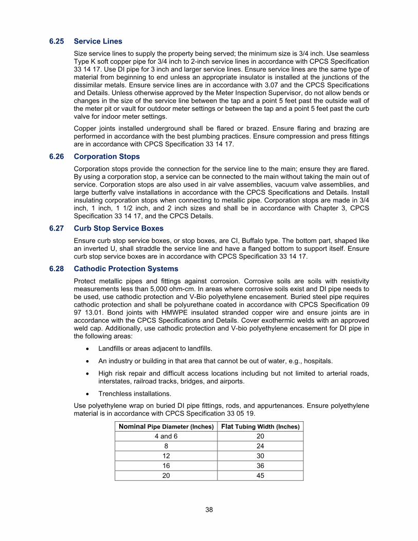
38
6.25 Service Lines Size service lines to supply the property being served; the minimum size is 3/4 inch. Use seamless Type K soft copper pipe for 3/4 inch to 2-inch service lines in accordance with CPCS Specification 33 14 17. Use DI pipe for 3 inch and larger service lines. Ensure service lines are the same type of material from beginning to end unless an appropriate insulator is installed at the junctions of the dissimilar metals. Ensure service lines are in accordance with 3.07 and the CPCS Specifications and Details. Unless otherwise approved by the Meter Inspection Supervisor, do not allow bends or changes in the size of the service line between the tap and a point 5 feet past the outside wall of the meter pit or vault for outdoor meter settings or between the tap and a point 5 feet past the curb valve for indoor meter settings.
Copper joints installed underground shall be flared or brazed. Ensure flaring and brazing are performed in accordance with the best plumbing practices. Ensure compression and press fittings are in accordance with CPCS Specification 33 14 17.
6.26 Corporation Stops Corporation stops provide the connection for the service line to the main; ensure they are flared. By using a corporation stop, a service can be connected to the main without taking the main out of service. Corporation stops are also used in air valve assemblies, vacuum valve assemblies, and large butterfly valve installations in accordance with the CPCS Specifications and Details. Install insulating corporation stops when connecting to metallic pipe. Corporation stops are made in 3/4 inch, 1 inch, 1 1/2 inch, and 2 inch sizes and shall be in accordance with Chapter 3, CPCS Specification 33 14 17, and the CPCS Details.
6.27 Curb Stop Service Boxes Ensure curb stop service boxes, or stop boxes, are CI, Buffalo type. The bottom part, shaped like an inverted U, shall straddle the service line and have a flanged bottom to support itself. Ensure curb stop service boxes are in accordance with CPCS Specification 33 14 17.
6.28 Cathodic Protection Systems Protect metallic pipes and fittings against corrosion. Corrosive soils are soils with resistivity measurements less than 5,000 ohm-cm. In areas where corrosive soils exist and DI pipe needs to be used, use cathodic protection and V-Bio polyethylene encasement. Buried steel pipe requires cathodic protection and shall be polyurethane coated in accordance with CPCS Specification 09 97 13.01. Bond joints with HMWPE insulated stranded copper wire and ensure joints are in accordance with the CPCS Specifications and Details. Cover exothermic welds with an approved weld cap. Additionally, use cathodic protection and V-bio polyethylene encasement for DI pipe in the following areas:
• Landfills or areas adjacent to landfills.
• An industry or building in that area that cannot be out of water, e.g., hospitals.
• High risk repair and difficult access locations including but not limited to arterial roads, interstates, railroad tracks, bridges, and airports.
• Trenchless installations.
Use polyethylene wrap on buried DI pipe fittings, rods, and appurtenances. Ensure polyethylene material is in accordance with CPCS Specification 33 05 19.
Nominal Pipe Diameter (Inches) Flat Tubing Width (Inches) 4 and 6 20
8 24 12 30 16 36 20 45
39
Cover buried harness rods with 4 inch flat width polyethylene tubing. Cover the entire joint with a wrap of 48 inch wide polyethylene sheet material over each set of lugs. Cover irregular shaped valves and fittings with flat 48 inch wide polyethylene sheet material.
Electrical isolation is required at dissimilar metal connections and at corporation stops in accordance with the CPCS Specifications and Details. Electrical isolation is achieved by installing dielectric insulating unions, bushings, gaskets, washers, and sleeves at couplings, flanges, and corporation stops. Use full face, unsegmented gaskets for electrically insulated flanges.
Use wax tape on DI pipe and fittings subject to submersion in manholes and in vaults not equipped with sump pumps. Ensure wax tape is in accordance with CPCS Specification 09 97 13.04.
6.29 Kickblocks Size concrete kickblocks for working pressure plus water hammer surge pressures as stated in 6.03, and soil bearing capacity. Ensure standard shapes and sizes of kickblocks are in accordance with the CPCS Specifications and Details. Construct kickblocks of Class B concrete in accordance with CPCS Specification 03 30 00 or of a premeasured, sacked industrial mix, e.g., Sakcrete or Quikrete. Ready-mixed concrete mixes need to be approved by Denver Water. Place kickblocks in accordance with 8.15.
6.30 Protective Concrete Pads Over Pipe Under unusual circumstances, it may be necessary to lay pipe at shallow depths. When this occurs, design concrete pads that support traffic loads without transmitting them to the pipe. Use approved insulation between the pipe and the pad to protect it from frost. Designs are subject to Denver Water’s approval.
6.31 Pipe Insulation Ensure pipe insulation is in accordance with CPCS Specification 40 42 13.
6.32 Casing Pipe Installation of mains through Denver Water ROW, or the ROW or easements of others, (e.g., highways and railroads) may require casing pipes to facilitate the installation of the main. The casing pipe may be required by the permitting agency or by Denver Water. The type of casing material and its properties shall be specified by the agency granting permission to cross. In the absence of a casing specification, Denver Water will specify the casing material. Such crossing will be subject to Denver Water’s approval to avoid conflicts in requirements or standards between Denver Water and the persons or agency granting permission to cross. Obtain final approval of the boring and casing methods and materials from Denver Water prior to construction. When a bore is not required to cross interference, Denver Water may require the installation of the main under the interference, see CPCS Specification 33 05 07.13.
6.33 Carrier Pipe Provide carrier pipe in accordance with CPCS Specification 33 05 07.
6.34 Miscellaneous Metalwork and Piping Ensure fabrication is equal to the best practice in modern fabricating shops. Ensure certified welders perform welding and ground exposed welds smooth. Properly remove weld spatter to Denver Water’s satisfaction. Exposed hardware, i.e., nuts, washers, bolts, and anchor bolts, shall be galvanized. For exposed metal that is to be buried, use two coats of CA-1200 mastic cold coating as manufactured by the Protecto Wrap Company of Denver, Colorado, except for metal with shop-applied coating approved by Denver Water. Paint metal exposed to the weather with one coat of rust inhibiting priming paint and two coats of aluminum paint unless otherwise directed by Denver Water. Clean surfaces of oil, grease, weld spatter, burrs, grit, dust, or other objectionable surface irregularities before painting. Use mineral spirits. Copper, aluminum, or galvanized pipe does not need to be painted unless directed by Denver Water.
40
Install miscellaneous piping in the best workmanlike manner. Cut threads on steel with sharp dies to standard depth and leave them clean cut and tapered. Properly seal threaded pipe joints with an approved joint compound applied on the male threads only. Solder or braze concealed joints for copper water tubing within buildings in accordance with the appropriate building code. Properly clean, flux apply, and solder the joint of the copper pipe with 95-5 tin-antimony solder in accordance with the best plumbing practice. Protect copper piping with a copper saddle soldered to the underside of the pipe where in direct contact with pipe hangers or other metal supports. Saddles may be made of split copper pipe.
6.35 Air and Vacuum Valves Use combination air release and vacuum valves for conduits; they may be required for transmission mains at the discretion of Denver Water. Install air release and vacuum valve assemblies at high points in the conduit or main, where there is an abrupt change of slope, at isolation valves where the conduit slopes away from the valve, or as determined by Denver Water, see CPCS Specification 33 14 19.
41
Chapter 7: Earthwork
7.01 Exploratory Excavation Earthwork includes clearing, grubbing, grading, excavation, fill, backfill, trenching, excess excavation, bedding, pipe zone and borrow material, and surface restoration that may be required to complete work. Expose underground utilities and structures that may interfere with construction and verify the location in advance to allow necessary relocations without delay.
Underground utilities can shift, separate, or become damaged when they are not supported or protected by the soil around them. Proceed with reasonable care to protect underground utilities within an excavation area. Do not disturb the bedding and/or the support of any utility without prior authorization from the utility owners/operators.
7.02 Excavation to Line and Grade Excavate to the lines and grades established by the approved plans. Excavate pipe trenches to a minimum depth of 6 inches below the bottom of the pipe. Do not deviate from grades unless approved in writing by Denver Water in accordance with Chapter 8.
7.03 Trenching Operations Cut existing asphalt or concrete surfacing vertically, in a straight line, and remove it from the jobsite prior to starting the trench excavation. Do not use it in fill or backfill unless approved in writing by Denver Water. Excavate the trench so that a minimum of 6 inches of clearance is maintained on each side of the pipe for proper placement and densification of bedding and pipe zone or backfill material. Ensure the maximum trench width, measured at the top of the pipe, is the OD plus 18 inches regardless of the type of pipe, type of soil, depth of excavation, or the method of densifying bedding and backfill in accordance with the CPCS Details.
Ensure the safety of workers as required by OSHA. Support the trench and use sheeting and shoring where required to prevent excessive widening or sloughing. Do not place excavated material closer than 2 feet from the top edge of the trench. Do not use heavy equipment or place it near the sides of the trench unless the trench is braced.
7.04 Excavation for Structures Excavate to dimensions that allow for the proper installation and removal of concrete forms or precast slabs and panels and allow the construction of necessary pipe connections, except as otherwise dictated by construction conditions. Do not extend the excavation below established grades. If that occurs, fill the resulting excess excavation with squeegee No. 57/67 or No. 4 coarse aggregate in accordance with ASTM C 33. Deposit it in horizontal layers up to 6 inches in thickness. Tamp layers to provide firm, unyielding support.
7.05 Blasting Blasting is generally allowed if a permit by the local authority having jurisdiction is granted. Denver Water sets the hours of blasting. Notify Property Owners and occupants of nearby structures or facilities in writing at least 3 days in advance of blasting. State the date and time of blasting and the Contractor responsible for it.
Control blasting to prevent the disturbance of existing structures and facilities. Do not make an excavation unduly large or irregular so that it shatters rock on the bottom or sides of an excavation or surface upon or against which concrete will be placed. If Denver Water determines that blasting may damage rock foundations or supports, concrete, or structures, excavation shall only continue by jack hammering, barring, wedging, or other Denver Water approved methods. Blasting in a trench shall occur only after bracing and shoring trench walls in a Denver Water approved manner. The Contractor is solely liable for blasting. Transport, handle, store, and use explosives and appurtenances in accordance with local, state, and federal laws.
42
7.06 Dewatering Keep pipe trenches or structure excavation free from water during pipe laying and related work. Ensure the dewatering method used provides for a completely dry foundation at the final lines and grades of the excavation and is in accordance with the NPDES and CDPHE’s permitting requirements. Use well points, sump pumps, rock, or gravel drains placed below subgrade foundations, or subsurface pipe drains. Dispose of water in a suitable manner that is not a hazard to public health and that does not cause a public inconvenience in accordance with the CDPHE permit. Do not drain water into work areas that are being completed or that are under construction. Continue dewatering until it is safe to allow the water table to rise in the excavations. Pipe trenches shall contain enough backfill to prevent pipe flotation of the carrier or the casing pipe. When pipe is laid in a casing or a tunnel longer than thirty pipe diameters, secure the pipe inside the casing or the tunnel so that flotation does not occur when the pipe is emptied. Do not allow water to rise until the concrete has set for a minimum of 24 hours and the forms are removed. Do not allow water to rise unequally against an unsupported structural wall.
7.07 Foundations on Unstable Soil If the bottom of the excavation is soft or unstable and cannot satisfactorily support the pipe or structure in Denver Water’s opinion, excavate and refill a further depth and width to 6 inches below grade with No. 4 coarse aggregate in accordance with ASTM C 33.
7.08 Pipe Bedding and Pipe Zone Material After completing the trench excavation and proper preparation of the foundation, place 6 inches of bedding material on the trench bottom for support under the pipe. Dig bell holes deep enough to provide a minimum of 2 inches of clearance between the bell and bedding material. Install pipe to ensure full support of the pipe barrel over its entire length. After adjusting the pipe for line and grade and making the joint, place and tamp the pipe zone material under the haunches of the pipe and in the previously dug bell holes.
NOTE: Tamping is the act of placing approved pipe zone material under the haunches of the pipe to ensure uniform support while paying attention to voids, bell holes, and sling holes.
The limits of bedding and pipe zone material shall be from 6 inches below the bottom of the pipe to 6 inches above the top of pipe. Approved backfill may then be installed to the ground line. For backfill and the compaction of backfill, see 7.09. Ensure bedding and pipe zone material is clean, free draining, poorly graded, unfrozen, non-friable, rounded (not crushed) squeegee with no clay balls or organic material. Expanded clay lightweight aggregate is acceptable with a max LA abrasion of 30%. Stockpile approved bedding and pipe zone material on the jobsite. Ensure material is in accordance with CPCS Specification 31 23 33.
7.09 Backfill and Compaction Restrain the pipe as necessary to prevent movement during backfill operations. Place material in lifts on both sides of the pipe. Tamp each lift, including the area under the haunches, with handheld tamping bars supplemented by walking in and slicing material under the haunches with a shovel to ensure voids are filled before placing each successive lift. Compact material by three or more passes with a vibratory plate compactor over the area between the sides of the pipe and the trench walls. Do not compact over the pipe. Do not use power-driven impact compactors to compact the pipe zone material. Backfill in a continuous manner and keep it as close to the pipe laying operation as possible. Ensure backfilling is in accordance with any additional requirements of appropriate agencies or private ROW agreements.
NOTE: The trench excavation may provide suitable backfill material above the pipe zone. Do not use wet, soft, or frozen material, asphalt chunks, or other deleterious substances for backfill. If the excavated material is deemed unsuitable for backfill by Denver Water, dispose of it properly and use a suitable material.
43
Backfill within 3 feet of any structure and the full height of walls. Use impervious, well graded material that does not contain 3 inch and larger stones. Use stockpiled material, other than topsoil, from the excavation for backfilling unless an impervious structural backfill is specified. Mechanical tamp backfill around structures. Place the material in 8 inch loose lifts, within 2% of the optimum moisture content (above or below), and compact it to 98% of compaction before placing each successive lift in accordance with ASTM D 6938 and ASTM D 698.
NOTE: Where specified, impervious structural backfill shall be CDOT Class 1 structural fill.
Use squeegee sand for backfill and fill within 1 foot around a composite meter pit and to the bottom of the top 1-foot ring. Place and mechanically compact the squeegee to ensure the meter pit does not deform more than 1 inch out of round at any point of its depth. Do not use the wheels of construction equipment for compaction.
7.10 Controlled Low Strength Material Request Denver Water’s permission to use CLSM for backfill in pipe zone and other backfill locations. The written request shall include a mix design from a ready-mixed concrete producer. Ensure CLSM products are in accordance with CPCS Specification 31 23 33.
7.11 Cleanup Upon completion of the work, remove rubbish, unused materials, concrete forms, etc. from the jobsite and leave the area clean. Remove excess excavation; if disposing of it on private property, provide the Property Owner’s written permission to Denver Water.
7.12 Surface Restoration Restore surface cuts to a condition equal to or better than prior to construction. In easements and cultivated or agricultural areas, remove topsoil (to a depth of 8 inches) from the area of disturbance and stockpile it. Evenly redistribute the topsoil to the original ground line or final grading plans after installing pipelines, appurtenances, and structures, and completing backfill and compaction.
7.13 Subgrade and Road Preparation Prior to installing water mains in dedicated streets, road construction shall have progressed to at least the subgrade stage. Ensure the road surface is smooth, clear of debris, and free from deep holes, ruts, and large rocks that may hamper main installation. Lay mains where the ground surface is near its final elevation, whether or not located in a dedicated street.

INTENTIONALLY BLANK
44
Chapter 8: Pipe Installation
8.01 Handling of Materials Many handling and installation procedures, tools, equipment, and materials require Denver Water’s approval. This ensures quality control; it does not render Denver Water liable for any means, methods, or injuries suffered or any equipment damaged.
Provide for the safety of workers as required by OSHA. Load and unload pipe and fittings by lifting to avoid shock or damage to materials. Do not drop materials. If any part of the coating or lining of pipe is damaged, make the replacement or repair of the damaged pipe to the satisfaction of Denver Water. Immediately remove from the jobsite any pipe or fittings that are not acceptable to Denver Water. Ensure pipe handling equipment and pipe handling methods are Denver Water approved.
Support stockpiled pipe on sandbags of sufficient size placed under the pipe. Prevent pipe from contacting the ground or any obstruction and allow for the proper use of slings. Securely cover pipe ends with polyethylene material or other suitable bulkhead to prevent the entry of animals, water, dirt, mud, or undesirable substances and prevent the drying out of the interior of the pipe.
8.02 Preparation for Installation Thoroughly clean each pipe or fitting of foreign material and keep it clean. Examine pipe for cracks and other defects, and examine bell and spigot ends. The pipe manufacturer shall supply non-toxic, water soluble joint lubricant that meets NSF/ANSI 61 and is approved by Denver Water.
8.03 Cutting and Fitting of Pipe Cut pipe to align with the location of fittings, line, or grade. Use tools approved by Denver Water. Ensure cuts are straight and true in a manner so that a smooth end is attained without damage to the pipe. Remove burrs from the ends of cut pipe and lightly rasp or file pipe ends.
NOTE: Do not use power-driven saws with abrasive discs (masonry blades) for dry cutting or beveling AC pipe. PVC pipe may be used in place of MOA AC pipe wherever cutting is necessary.
8.04 Pipe Alignment and Grade Lay pipe to set line and grade within a tolerance of ±3 inches. On slopes of zero grade lay pipe to grade. Install fittings, valves, and hydrants at specified locations and elevations. When pipe is laid on curves lay it to the alignment. Keep pipe in alignment by placing joints or bends on the curve. Use bends whenever individual deflections exceed those specified by the manufacturer.
Ensure the depth of cover over pipe is a minimum of 4 1/2 feet, measured from ground line to top of pipe. If difficulties arise when crossing an interference, deviations from 4 1/2 feet of cover are allowed where approved in writing by Denver Water. In unusual circumstances, cover over the pipe can be a minimum of 3 feet and a maximum of 10 feet if approved by Denver Water. Use pipeline insulation only with written approval by Denver Water; ensure insulation is in accordance with 6.31 when transmission or distribution mains are installed at a depth of cover less than the building code adopted County frost depth. Pipeline insulation may require additional cathodic protection of the pipeline or upgraded protective coatings.
Changes in alignment and grade need to be authorized by Denver Water and accomplished by the installation of additional fittings. Joint deflection is allowed only when installing pipe on horizontal or vertical curves; do not exceed manufacturer specifications. Lay pipe with the bell ends facing the direction of the pipe being laid unless otherwise directed by Denver Water.
8.05 Deviation Occasioned by Other Structures Denver Water will determine the best method of correction whenever obstructions not shown on plans interfere to such an extent that an alteration in plans is required. Denver Water's Inspector may change the plans and order a deviation from line and grade or arrange with the Owners of the structure for its removal, relocation, or reconstruction. The licensee shall pay the costs for changes.
45
8.06 Temporary Bulkheads and Pneumatic Plugs Install watertight temporary plugs (bulkheads or pneumatic) that are approved in writing by Denver Water and designed to prevent human tampering and environmental contamination at the ends of installed pipe when unattended. Install plugs before storm events and before leaving the site unattended. Clean and disinfect plugs in accordance with AWWA C651 with an NSF 60 certified sodium hypochlorite solution using a swab or spray application method before installation. Keep plugs free from contamination during storage and do not use them in nonpotable applications (e.g., sanitary sewer, storm water systems, and recycled water). Immediately report any tampering or contamination events to Denver Water.
8.07 Frost Do not install pipe or appurtenant structures on a foundation into which frost has penetrated or when there is a danger of ice formation or frost penetration at the bottom of the excavation as determined by Denver Water. Do not begin installation unless backfilling can be completed before the formation of frost and ice.
8.08 Ductile Iron Pipe Before joining two lengths of DI pipe, clean the inside of the bell, the outside of the spigot end, and the rubber gasket to remove oil, grit, excess coating, and other foreign matter. Flex the correct type of rubber gasket inward and insert it into the gasket recess of the bell socket. Apply a thin film of joint lubricant to the inside face of the gasket, the spigot end of the pipe, or both. Place the spigot end of the pipe into the bell end to prevent the joint from contacting the ground. Complete the joint with a slow, steady pressure. Mark pipe furnished without a depth mark before assembly to ensure insertion is to the full depth of the joint. File or ground the spigot end of field cut pipe to resemble the spigot end of manufactured pipe. Bond DI pipe in corrosive soils in accordance with 6.28.
Before joining mechanical joint DI fittings to DI pipe, clean the outside of the spigot, the inside of the bell, and the rubber gasket to remove oil, grit, excess coating, and other foreign matter. Lubricate the joint with a soap solution. In cold weather, the joint may be dry assembled if approved in writing by Denver Water. Exercise caution when making dry joints. Slip the gland on the spigot end of the pipe with the lip extension of the gland toward the socket or bell end. Place the rubber gasket on the spigot end with the thick edge toward the gland. Push pipe in until the spigot end fully penetrates the bell. Press the gasket into place evenly within the bell around the entire joint. Move the DI gland along the pipe into position for bolting. Insert bolts and screw nuts finger tight; use a torque-limiting wrench for final tightening to the manufacturer’s specifications.
Install pipe equipped with locking gaskets providing mechanical joint restraint according to the manufacturer’s recommendation. Spray paint the bell end of the locking gasket pipe safety red. Tighten nuts spaced 180 degrees apart alternately to produce equal pressure on the gland. Wrap mechanical joint fittings with polyethylene encasement material in accordance with 6.28.
When installing bolted sleeve-type couplings ensure connecting pipe ends, couplings, and gaskets are clean and free of dirt and foreign matter; give attention to the contact surfaces of pipe, gaskets, and couplings. Assemble and install the couplings in accordance with the recommendations and instructions of the coupling manufacturer. Wrap bolted sleeve-type couplings with polyethylene encasement material in accordance with 6.28.
For bolt couplings use wrenches of the type and size recommended by the coupling manufacturer. Tighten bolts to secure a uniform annular space between the end rings. Tighten the body of the pipe and the bolts the same amount. Tighten diametrically opposite nuts progressively and evenly in accordance with the CPCS Details. Use a torque-limiting wrench for final tightening to the coupling manufacturer’s specifications.
46
8.09 Polyvinyl Chloride Pressure Pipe Before joining two lengths of PVC pipe, clean the inside of the bell or coupling, the outside of the spigot, and the elastomeric gasket to remove foreign material. Lubricate the joint and the rubber gasket in accordance with the pipe manufacturer's specifications. Use the correct elastomeric gasket, compatible with the annular groove of the bell. Insert the elastomeric gasket into the annular groove of the bell or coupling in accordance with the manufacturer's recommendations. Mark pipe furnished without a depth mark before assembly to ensure insertion is to the full depth of the joint. Align the spigot and the bell or coupling and push it in a smooth, steady motion until the reference line on the spigot is flush with the end of the bell or coupling.
Install pipe equipped with locking gaskets providing mechanical joint restraint according to the manufacturer’s recommendation. Spray paint the bell end of the locking gasket pipe safety red.
Cover pipe stored outside and exposed to sunlight for longer than 30 days with an opaque material, e.g., canvas. Do not use clear plastic sheets to cover pipe. Provide air circulation under the covering. These requirements are in addition to 8.01.
PVC pipe has reduced flexibility and impact resistance as temperatures near freezing. Use caution when handling it in cold weather.
Install 6 inch wide detectable aluminum foil plastic backed blue tape, manufactured by Pro-Line Safety Products or Thortec, indicating a buried water line is installed 12 inches to 18 inches below surface grade. Install minimum AWG 12 solid copper wire with 0.03 inch of blue PE insulation to the pipe with 2 inch wide PVC tape. Splice tracer wire in accordance with the manufacturer’s recommendation. Run tracer wire in accordance with the CPCS Details. In lieu of tracer wire inside Denver and Total Service Contract Areas, 3M passive marking balls may be used in accordance with the CPCS Details.
8.10 Valves and Valve Boxes Handle valves in a manner that prevents injury or damage. Operate valves prior to installation to ensure they are in good condition. Set valves and join them to the pipe in the manner previously specified for cleaning, laying, and joining mechanical and push-on joints; ensure valve stems are plumb. Wrap valves with polyethylene encasement material in accordance with 6.28. Place valves at the point on the main that would be intersected by the street property line if extended, and as outlined in 5.12. Deviations are at the discretion of Denver Water.
Include valve boxes with each valve; ensure they do not transmit shock or stress to the valve, are centered and plumb over the wrench nut, and are set to the elevation determined by Denver Water.
8.11 Fittings Provide mechanical joint fittings in compliance with the CPCS Specifications. Set and join fittings on DI pipe as outlined in 8.08. Where PVC pipe is inserted into CI or DI fittings, remove beveled portions of the spigots to accommodate the expansion characteristics of the plastic to the lesser depth of the bell. Wrap repair fittings and stainless steel repair clamps with polyethylene encasement material as outlined in 8.20 when installation occurs during a main repair.
8.12 Tapping Sleeves Do not install taps on PVC pipe containing water under pressure. The tapping of dry mains is only allowed on PVC pipe. AC, CI, or DI pipe may be tapped under pressure or wet. Space tapping sleeves used for domestic service lines and fire service lines to give adequate clearance between the completed service lines and meter pits/vaults, fire hydrants, and similar underground structures. Do not use two tapping sleeves side-by-side or back to back as a substitute for a cross.
8.13 Fire Hydrants Field stake hydrants for location and grade; ensure the final location matches the plans. The center of the hydrant’s traffic flange shall be 3 inches above the ground line or top of the curb. Ensure hydrants stand plumb, have a minimum horizontal clearance of 5 feet, and are in accordance with the CPCS Details.
47
Connect each hydrant to the street main by a 6-inch DI branch line. Replace existing branch lines that are not entirely DI pipe with DI pipe from the hydrant tee or tapping sleeve to the hydrant. Install an independent 6-inch gate valve on each branch line. Firmly anchor the valve to a mechanical joint tee with a 6-inch anchor coupling (also called a swivel adapter or a locked hydrant adapter) or to a mechanical joint anchor tee (also called a swivel tee or a locked hydrant tee). Anchor the branch line to the valve by mechanical joints.
Exception: When making a wet tap for a hydrant use a tapping valve and saddle in place of the mechanical joint tee, swivel adaptor, and valve.
Place a minimum of 1/3 cy of cobble or brick sized crushed granite from the bottom of the trench to at least 12 inches above the hydrant’s barrel flange and to a minimum of 12 inches around the elbow. The bottom of the trench to the bottom of the hydrant elbow shall be at least 6 inches.
Encase the DI branch line and fittings in polyethylene wrap from the hydrant base up to and including the tee. Use the type and installation of polyethylene as specified in 8.20. Use bedding and pipe zone material from 6 inches below to 6 inches above the branch line. Use bedding material as specified in 7.08.
8.14 Fire Service Line Connections Install fire service line connections in accordance with Chapter 3 and the CPCS Details using restrained DI pipe. Ensure the fire service line connection has a valve 2 feet to 5 feet from the property line that is on the street side of the property line. Protect the fire service line connection from corrosion, see 6.28. Submit requests for residential fire service line connections with the plans to Denver Water for approval.
8.15 Kickblocks Construct kickblocks at bends and fittings that require support due to unbalanced line thrust. Ensure outlets, cover bolts, nuts, clamps, and other fittings are accessible. Place a bond breaker between the pipe and the kickblock to aid in future removal. If placing a large kickblock, separate it into sections by a suitable material. Bearing surface areas are minimum areas to bear against the undisturbed trench wall. If the soil bearing capacity is insufficient to provide adequate support based on minimum bearing areas in accordance with the CPCS Details, increase the minimum bearing area to a size that ensures support restraint. In every instance, the kickblock shall bear against undisturbed earth.
Before placing concrete, clean the equipment used in mixing and transport. Remove debris, water, and ice from the placement area. Place concrete in the presence of the Denver Water Inspector unless inspection is waived prior to the placement. Do not place concrete on frozen subgrade.
To form concrete kickblocks and anchors, bulkhead around the shape of the kickblock or anchor with wood, burlap sacks, or reinforced paper sacks filled with sand or earth. Construct sacks of a size easily handled when full and left in place in the trench. Remove wood forms before backfilling.
Do not keep horizontal struts or braces required for trench shoring in concrete kickblocks. Prior to placing concrete, Denver Water will inspect and approve the forms and ditch bank. When concrete is placed against the ground without the use of forms, thoroughly moisten the ground or make other provisions to prevent the ground from drawing water in from the concrete. Ensure newly placed concrete sets undisturbed for a minimum of 24 hours. Backfill may be placed over kickblocks after the surface has set sufficiently and the kickblocks are able to resist the weight of the backfill. Do not tamp or compact above the kickblock for a minimum of 24 hours after placement.
8.16 Concrete Structures Produce forms that meet the shapes, lines, and dimensions of the concrete structures shown on plans. Design formwork according to the loads and allowable stresses outlined in ACI 347. Make forms of wood, metal, or other materials approved by Denver Water. Wet wooden forms, except in freezing weather, or apply a form release agent. Produce forms with a smooth concrete finish to the tolerances outlined in ACI 301. Do not use form material with raised grain, torn surfaces, worn edges, patches, dents, or other defects that impair the texture of the concrete surface.
48
Make forms mortar tight and brace or tie them to maintain proper position and shape during and after concrete placement. Use embedded metal ties with snap-off ends for internal form ties; do not use wire ties. Do not withdraw form ties through the walls. Chamfer exposed edges with a 3/4 inch, 45-degree bevel. Clean the surfaces of forms and embedded items of foreign material before placing concrete. Follow the recommendations of ACI 347 for form removal times under normal conditions. Denver Water will determine if additional time is required. Remove forms in a manner that ensures the integrity of the structure and its surfaces.
Mix and deliver ready-mixed concrete in accordance with ASTM C 94. To bring the slump within the required limits, water may be added to the mix one time only: immediately upon arrival at the jobsite. Convey concrete from the mixer to the place of final deposit by methods that prevent separation. The size and design of equipment for chuting, pumping, and conveying concrete shall ensure a continuous flow of concrete at the discharge end without separation of materials. Do not allow concrete to free fall a vertical distance greater than 5 feet during its discharge into forms.
Deposit concrete as near as possible to its final position to avoid segregation due to handling or flowing. Place it at a rate that is continuously plastic and flows readily between reinforcing steel. Do not use partially hardened concrete and concrete contaminated by foreign materials. Deposit concrete in continuous layers of such thickness that no concrete is deposited on or against concrete that has hardened to form seams or planes of weakness within the area or section. Do not place concrete in lifts exceeding 18 inches in thickness. Adjust the mix design as necessary to prevent the accumulation of water on the surface of the concrete due to water gain, segregation, or other causes during placement and consolidation.
When placing concrete during cold weather, as defined in ACI 306, ensure the temperature of the concrete mix during placing is not lower than 55°F and concrete work is in accordance with the recommended practices of ACI 306. When placing concrete during hot weather, as defined in ACI 305, ensure the temperature of the concrete mix during placing is not higher than 85°F and concrete work is in accordance with the recommended practices of ACI 305. Do not cool or warm plastic concrete mixtures without Denver Water’s approval.
Thoroughly consolidate concrete with internal vibrators as recommended in ACI 309. Denver Water will need to approve the size, type, and number of vibrators used for each concrete placement. Thoroughly work the concrete around the reinforcing steel, around embedded items, and into the corners of the forms. Supplement vibrators by spading, rodding, or forking to eliminate honeycombing at the form face and voids around embedded items.
When concrete surface finishes are not shown on plans, screed and wood float finish unformed flat surfaces. Steel-trowel interior floor surfaces with a light broom finished to Class A tolerance in accordance with ACI 301. Do not apply water to the concrete surface during any phase of finishing operations. Do not perform concrete finishing while water is present on the surface.
Construction joints not shown on plans will need to be approved by Denver Water. Prior to placing adjoining concrete, clean and remove laitance from concrete surfaces where joints are made. Cut contraction control joints 1/4 of the depth of the slab. When using power saw cutting methods, cut joints as soon as the concrete surface is firm enough not to be torn or damaged by the saw blade. During cutting, washing, and rinsing concrete contraction control joints, use water that does not stain, discolor, or affect exposed surfaces of the structures or damage the environment of the project or adjacent areas. Methods of wastewater disposal are subject to Denver Water’s approval.
Cure concrete by a method recommended by ACI 308. When the daily mean ambient temperature is above 40°F, continuously cure finished concrete for a minimum of 7 days or for the time necessary to attain 70% of the specified compressive strength, whichever is less. When the mean daily ambient temperature is 40°F or lower, continuously cure finished concrete at a minimum temperature of 55°F for the period recommended by ACI 306 to prevent damage from early-age freezing and provide service category strengths required for each placement. Cure concrete upon removal of forms or as directed by Denver Water. Cure concrete on slabs as soon as the water on the slab surface has evaporated or as directed by Denver Water. Repair surface defects, including fins, tie holes, and honeycombed areas down to solid concrete in accordance with ACI 301.
49
8.17 Reinforcing Steel for Concrete Structures Form reinforcing steel to the dimensions shown on plans. Make bends in bars cold. Do not use bars with kinks or bends not shown on plans. Place splices where shown on plans. Splices at other locations need to be approved in writing by Denver Water. Lap welded wire mesh one space and securely wire together.
Before embedding reinforcement, clean bars and bar supports of flaky rust, loose mill scale, dirt, grease, and other foreign substances. After placement, reinforcement will be inspected for compliance with requirements as to size, shape, length, splicing position, and amount.
Before placing concrete, place steel reinforcing bars and welded wire fabric within forms; secure them with annealed wire. Tie the bars in walls at every other intersection at a minimum, or as directed by Denver Water. Tie the bars in slabs at every intersection. Support reinforcement in slabs on chairs of metal, plastic, or concrete to prevent dislocation during slab construction. Do not construct splices not shown on plans without Denver Water’s approval.
Protect reinforcing steel by placing concrete to the thickness shown on plans. If the thickness is not shown, ensure concrete placed against the ground without the forms is not less than 3 inches, concrete exposed to weather or the ground in forms is not less than 2 inches for bars larger than 5/8 inch in diameter and 1 1/2 inches for bars 5/8 inch diameter and smaller, and formed surfaces not in contact with the ground or exposed to weather have a thickness of 3/4 inch at a minimum.
8.18 Joint Restraint Devices Use joint restraint devices at bends and fittings where required and for the following installations: fire hydrants, fire service line connections, 3 inch and larger domestic service line connections, vertical bends, reducers, vertical and horizontal offsets, horizontal bends, isolation valves, and fittings, bulkheads and plugs, bored casings, when Denver Water determines the bearing capacity of the soil is not sufficient to provide adequate restraint, and when Denver Water identifies potential future development that may use or connect to the water main to be installed
Restrain horizontal and vertical offsets and reducers on each side of the fitting. For other fittings, ensure the length of tied pipe is in accordance with the CPCS Details. Ensure joint restraint devices and appurtenances are in accordance with 6.05 and the CPCS Details.
8.19 Connections to Denver Water's System Denver Water will be present during the construction of connections; connections are subject to Denver Water’s approval. Only one connection to the existing system will be allowed until the conditions and tests outlined in 8.23 are met.
Denver Water does not guarantee the water tightness of its valves on existing facilities. If existing valves leak, Denver Water will help reduce the leakage; however, the Contractor shall use proper methods to work with the resulting leakage. Connections will not be installed or allowed by Denver Water unless the water supply is protected as required against actual or potential cross-connections. Water service to premises will be discontinued if a BFPA is required in accordance with 5.05 and is not installed, tested annually, and maintained, if it has been removed or bypassed, or if an unprotected cross-connection exists. Water service will not be restored until such conditions or defects are corrected.
It may be necessary to operate existing Denver Water valves when connecting to its system. If this is necessary, the Contractor shall give Denver Water 2 days’ notice and Denver Water personnel will operate the valves with the Contractor present.
The installation of a connection that requires the closing of existing valves may cause an outage of water to existing Denver Water customers. The Contractor shall notify the affected customers in writing 24 hours in advance of service interruptions and deliver the notices by hand to each customer. If a customer cannot be contacted, the Contractor shall leave the written notice at the door. The Contractor shall notify the fire department having jurisdiction for the affected area 2 days in advance of service interruptions and provide a description of the boundaries of the affected area and the location of fire hydrants in that area.
50
A normal outage is a maximum of 8 hours. If an outage is to be longer than 8 hours, perform the work in a manner that minimizes inconvenience to customers, e.g., working at night in a continuous operation until service is restored. A connection that requires an outage longer than 8 hours will be subject to review by Denver Water to determine the appropriate timing of the connection. If there is an industry or building in the area that cannot be out of water, e.g., a hospital, take appropriate means to provide and convey water. The water and the means of its conveyance will be approved in writing by Denver Water.
8.20 Cathodic Protection Systems Install cathodic protection and electrical insulation as required by Denver Water. Electrically insulate between dissimilar materials and at service line connections to metallic water mains. Wherever it is necessary to join pipe of dissimilar metals, provide a method of insulating against the passage of electrical current that is approved by Denver Water. Exercise caution during installation to prevent electrical conductivity across joints. After the insulating joint installation is complete, Denver Water will test the joint. If the insulated joint fails the test, remove it, inspect it, and make repairs. The joint shall then be reinstalled and tested. This process shall continue until the joint passes the test. Typical insulated joints are outlined in 6.28 and shall be in accordance with the CPCS Details.
DI pipe, joint restraint, fittings, tie rods, and appurtenances shall be polyethylene encased to prevent contact between the pipe and bedding material; it is not intended to be a completely airtight and watertight enclosure. Apply polyethylene pipe wrap to DI pipe as outlined in 6.28 and in accordance with the CPCS Details. Use a polyethylene pressure-sensitive tape, 2 inch wide 10 mils thickness, to close seams or hold overlaps. Keep exposure to sunlight to a minimum as prolonged exposure deteriorates polyethylene film.
Before Denver Water will tap a water main, the trench, pipe, and polyethylene wrapping shall be in a state of readiness. Repair damage to polyethylene pipe wrap in the trench prior to and during the backfill process to the satisfaction of Denver Water. Denver Water will repair damage to the pipe wrap caused by tapping the main.
8.21 Chlorination Disinfect main extensions and Distributor main extensions, with the exception of those in the recycled system, in accordance with AWWA C651 with an NSF 60 certified sodium hypochlorite solution and the requirements of the official health authority having jurisdiction prior to acceptance by Denver Water. The chlorinating agent and the method of application will be approved by Denver Water.
Complete the chlorination of the finished pipeline prior to hydrostatic testing. Before filling the pipe with water, clean it and ensure it is free of debris to the satisfaction of Denver Water. The Water Quality Operations Group may disinfect by chlorine slurry with a minimum 1% chlorine solution in accordance with the Water Quality Standard Operating Procedures made available at the pre-construction meeting. A single point of connection to the Denver Water system is required for injection of the chlorine slurry by Denver Water. Disinfection by chlorine swabbing may be used for 16 inch and smaller mains less than 100 feet in length, in accordance with AWWA C651.
Chlorine tablets may be used for 12 inch and smaller mains. Denver Water will not provide labor or material for disinfection by chlorine tablets to the Contractor for the installation of mains under private contract. Attach chlorine tablets certified to NSF/ANSI 61 to the inside top of the pipe with an approved adhesive, e.g., Dow Corning 748 Multipurpose Sealant, prior to pipe installation in the trench. For 16 inch and larger pipe, chlorine slurry is required to be fed into the water used to fill the pipe.

51
Number of Hypochlorite Tablets of 5 Gram Strength Required for a Dose of 50 Milligrams Per Liter*
Pipe Length (Feet)
Pipe Diameter (Inches)
6 8 12 13 or less 2 2 5
18 2 3 6 20 2 3 7
*Based on 3 3/4 grams of available chlorine per tablet.
After the pipe is filled with water and chlorine, hold the chlorinated water in contact with the pipe for 24 hours. At the end of the 24-hour period, the official health authority having jurisdiction will test the water to ensure a residual chlorine content of no less than 25 mg/L. Thoroughly flush the pipeline to remove the heavily chlorinated water. Attain a permit from CDPHE’s WQCD prior to flushing. The application can be obtained online: Water Quality - Permits | Department of Public Health & Environment (colorado.gov) or by calling (303) 692-3500. The permit requires dechlorination, consumptive use, or land applications prior to discharge. Cautiously flush the pipeline to prevent property damage and danger to the public. Contain discharges of water from blowoff assemblies or other appurtenances or discharge it in a manner approved by Denver Water and CDPHE.
Collect samples of water for bacteriological examination and residual chlorine content testing before the pipe is put into service. Testing of residual chlorine and sampling shall be carried out by the official health authority having jurisdiction.
8.22 Hydrostatic Testing Perform hydrostatic testing on newly installed water mains and fire service lines after field-placed concrete has adequately cured as defined for kickblocks in 8.15. Denver Water will perform testing at the time of chlorination by Water Quality Operations. Projects disinfected by chlorine tablets or swabbing may be tested by the Contractor. Notify Denver Water 24 hours in advance of testing; testing shall occur in the presence of Denver Water.
Use one of the following methods for supplying potable water for testing: take water from a nearby pressurized water source that was previously chlorinated, tested, and accepted, e.g., a fire hydrant; have a state licensed chlorinated water truck that is used exclusively for the transportation of potable water and has a minimum capacity of 300 gallons deliver water to the site; use a previously tested, chlorinated, and accepted water main that is pressurized and is to serve the new main extension by tapping it on the pressurized side of the closed valve.
The method of supplying water and the source of water for testing needs to be certified and approved by Denver Water. Do not use barrels or rented tanks to supply water for testing.
Ensure the pipeline is properly backfilled and ready for testing. Ensure bulkheads, pumps, taps, and appurtenances necessary to fill the pipeline and maintain the required pressure are in place. Fill the pipeline with potable water. Apply the test pressure of 150 psi to the pipeline by means of a sanitized continuously operating pump that is equipped with a bypass valve for pressure regulation. Fill the pipeline at a rate that does not cause surges and does not exceed the rate at which air can be released. Properly purge air in the line. Denver Water will require a tap to purge the line where blowoffs or hydrants are not available or are not effective in purging air; the location and size of the tap are at the discretion of Denver Water.
While the test pressure is maintained at 150 psi, examine the pipeline to locate and repair leaks. Remove and replace faulty pipe or fittings. After visible leaks are stopped, maintain the full test pressure continuously for 1 hour. If any leakage is present, the pipeline will not be accepted. Repair the pipeline, rechlorinate it as outlined in 8.21, and test it until it meets the requirements.
52
8.23 Acceptance and Release for Taps Denver Water will accept the main and release it for taps when a release is provided by the health department having jurisdiction and the main and appurtenances are installed, pertinent notes and measurements are made, required tests are passed, and test outcomes provided to Denver Water. Required tests include the following: a chlorination test and any other tests required by the official health authority having jurisdiction, see 8.21; a compaction test indicating trench backfill meets Denver Water requirements performed under the direction of a PE, see 7.09; a hydrostatic test, see 8.22; a valve and valve box inspection, see 8.10.
8.24 Blowoff Assembly Install a blowoff assembly in installations where the main is to be permanently dead-ended, e.g., a cul-de-sac. Where the main is to be temporarily dead-ended, e.g., the boundary of a subdivision filing, install a blowoff unless a fire hydrant, which can serve additionally as a blowoff, is located at the main's temporary end. Install the blowoff at a right angle to the main and on the side that allows the water to drain away from the main to the nearest gutter. A 2-inch blowoff assembly is standard for 12 inch and smaller mains. Under special conditions, e.g., a long run with only a few taps, a nonstandard 2 inch and larger blowoff may be required. A 6-inch blowoff assembly is standard for 16-inch DI pipe and larger. Install the blowoff assembly in accordance with the CPCS Details.
8.25 Sewer Crossings When water mains or associated piping cross over or under a sanitary or storm sewer constructed of vitrified clay or concrete pipe, replace the sewer or protect it as shown on plans during installation, as outlined herein, or as otherwise directed by Denver Water.
When the sewer is 15 inch diameter or smaller and crosses over water mains or associated piping and protection is not otherwise shown on plans, where applicable, replace the sewer with polywrapped Special Thickness Class 50 DI pipe manufactured in accordance with AWWA C151 or Type PSM SDR 35 PVC sewer pipe manufactured in accordance with ASTM D 3034. Make reconnections to the existing sewer pipe with watertight, flexible couplings approved by Denver Water and the authority having jurisdiction over the sewer being replaced. Restore drains that exist under the sewer in a manner that prevents any flow from entering the trench.
When the sewer is larger than 15 inch diameter, take precautions to protect the sewer during the installation of water mains or associated piping. Restore drains that exist under the sewer in a manner that prevents any flow from entering the trench.
When water mains or associated piping cross over the sewer with less than 2 feet of clearance between the pipes, encase the sewer with a minimum of 6 inches of concrete from the springline to 6 inches above the top of the sewer. Extend the encasement along the centerline of the sewer for a minimum of 1 foot beyond the OD of the water main or associated piping at each end of the encasement in accordance with the CPCS Details.
In addition, when water mains or associated piping cross under a sewer, replace bedding material around the sewer to a point at least 1 foot above the top of the sewer pipe for 15 inch diameter or smaller sewers and to at least springline for larger diameter sewers. Thoroughly compact and consolidate bedding material to support the sewer. Do not place water mains closer than 18 inches as measured from the outside bottom of the sewer pipe to the top of the water pipe. Do not cut a sewer without the express consent of the authority having jurisdiction over the sewer. Typical trench sections shall be in accordance with the CPCS Details.
8.26 Trenchless Installation Trenchless installation by boring or jacking may be used as a method of installing mains in accordance with the CPCS Specifications using a casing pipe and a carrier pipe. Prior to any work, the Contractor shall submit a bore plan drawing to Denver Water with a vertical scale of 1 inch equals 2 feet and a horizontal scale of 1 inch equals 20 feet. Include the bore entry point and angle, bore exit point and angle, ground line, deflection and radiuses of the pilot bore, and existing utilities with minimum vertical and horizontal clearances. Confirm the alignment and elevation of critical utilities by potholing, using vacuum excavation, or other suitable excavation method. Ensure mains cross perpendicular to the public ROW or easement.
53
8.27 Horizontal Directional Drilling With the approval of Denver Water, HDD may be used as a method of installing mains. HDD is a trenchless methodology of installing pipe that consists of three primary stages: piloting (drilling of a pilot hole), reaming (pilot hole enlargement), and pull-back (installation of the carrier pipe). The directional drilling machine generally consists of a hydraulically powered system that rotates and pushes a hollow drill pipe into the ground at a variable angle while delivering a pressurized fluid mixture to a guidable boring head.
Prior to any work, the Contractor shall submit a pilot bore plan drawing to Denver Water with a vertical scale of 1 inch equals 2 feet and a horizontal scale of 1 inch equals 20 feet. Include the bore entry point and angle, bore exit point and angle, ground line, deflection and radiuses of the pilot bore, and existing utilities with minimum vertical and horizontal clearances. Confirm the alignment and elevation of critical utilities by potholing, vacuum excavation, or other suitable excavation method.
Use a self-contained, closed, drilling fluid mixing system of sufficient size to mix and deliver drilling fluid (composed of bentonite clay, potable water, and appropriate additives) to lubricate the cutting head during the drilling operation and stabilize the reamed bore path prior to and during pull-back. Use an electronic walkover tracking system to provide a continuous and accurate determination of the location of the drill head during the drilling operation. It shall enable the driller to guide the drill head by providing real-time feedback regarding the azimuth (horizontal direction) and inclination (vertical direction) of the tool face. Record readings every 10 feet by plotting on a scaled drawing and providing them to Denver Water. Denver Water will need to approve the location of the pilot hole prior to the reaming of the hole.
Increase the bore hole diameter to 1.2 to 1.5 times the OD of the largest part of the carrier pipe to accommodate the pull-back operation. The Contractor shall choose the type of hole opener or back reamer used with regard to the types of subsurface conditions identified during the pilot hole drilling operation. Stabilize the open bore hole by pumping bentonite drilling slurry though the ID of the drill pipe and through openings in the reamer.
Assemble the carrier pipe according to the manufacturer’s specifications and install it using the cartridge assembly method or assembled-line methods. The cartridge assembly method assembles individual sections of pipe in a secured entry and assembly pit. The assembled-line method consists of the preassembly of multiple pieces of pipe with a subsequent pulling installation into the bore hole as a long pipe string. For both methods, attach a pulling eye to the pulling head on the lead stick of pipe that in turn attaches to a swivel on the end of the drill pipe. Seal the end of the pipe to prevent contamination during the pull-back operation. Secure tracer wire, as required for PVC carrier pipe, to the pipe prior to the pull-back operation. Support the carrier pipe as it enters the bore hole to minimize forces on the pipe during pull-back. Carry out pull-back in a continuous manner until the pipe reaches the original entry side of the bore. Follow the manufacturer’s recommendations regarding bend radius and tensile strength. Following pull-back, allow the pipe to achieve mechanical and thermal equilibrium with its surroundings prior to cutting it at either end.
Dispose of drilling fluid in accordance with applicable regulations. Restore the area to the conditions required by applicable regulations. Conduct cleaning, flushing, and hydrostatic testing of the pipe as specified in these Standards. Provide an as-built plan and profile to Denver Water based on electronic walkover system readings showing the horizontal and vertical location of the installation.
8.28 Pipe Bursting Pipe bursting may be used as a method of replacing distribution mains with the written approval of Denver Water. Pipe bursting is a trenchless methodology that involves the insertion of a conical shaped static bursting head into the pipe to fracture the pipe, thereby displacing the pipe fragments outward as the new replacement main is pulled in to replace the existing pipe.
54
Static pipe bursting equipment includes the bursting head, pulling machine, segmented pulling rods, hydraulic power unit and associated restraint, and attachment equipment. Ensure the bursting head system is designed and manufactured to force its way through the existing pipe by fragmenting the pipe, pushing the fragments into the surrounding soil, and allowing for the pulling of the replacement pipe into place. Ensure the bursting head system is conical in shape and centered in the pipe, fractures the pipe by applying radial pressure, and expands the surrounding soil and the fragments to the proper size to accept the replacement pipe. Do not use the pull head to which the replacement pipe is attached to expand or otherwise increase the diameter of the existing fragmented pipe. Ensure the pull head uses a positive through-bolt design assuring a smooth wall against the pipe cross-section. Ensure pulling rods are segmented with snap lock connections. Use cutting wheels to assist in the demolition and fragmenting of the pipe. The system shall maintain automatic thrust and pull-back and pull from either side of the bursting head system. Use fusible PVC pipe or RJIB Certa-Lok in accordance with CPCS Specification 33 05 31.13.
Identify existing underground utilities. Expose facilities located within an envelope of possible impact as a result of the pipe bursting operation. Provide temporary water service to customers affected by outages as approved by Denver Water. Remove service connections to the pipe being replaced. Ensure access pit excavation at the point of insertion of the fusible PVC pipe provides for a pipe radius larger than that recommended by the PVC pipe manufacturer. Support fusible PVC pipe on rollers; do not allow it to contact paving, grass, or earth during the fusion process and staging for insertion. Attach tracer wire, as approved by Denver Water, to the pulling head and install it along the pipe. Following completion of the operation, push the pipe back toward the insertion point until a small amount of movement is realized at the insertion point.

INTENTIONALLY BLANK
55
Chapter 9: Transmission Mains
9.01 General Due to changing trends in the design of subdivisions (e.g., curved streets, only one or two access roadways, and cul-de-sacs), water mains may not be sized using the hydraulic grid system common to most of Denver. In some instances, the maximum water demand within the subdivisions is exceeding the allowable design capacity of a 12-inch distribution main yet is often considerably under that of a 24-inch conduit. As a result, 16 inch and 20-inch transmission mains are being used.
9.02 Other Applicable Standards Standards applicable to 4 inch through 12-inch mains are also applicable to 16 inch and 20-inch transmission mains along with the following requirements or exceptions. In case of a conflict, this Chapter governs for 16 inch and 20-inch pipe.
9.03 Design Size and design transmission mains in accordance with Chapter 5. Supply lines by dual feeds unless otherwise directed by Denver Water. Place isolation valves to minimize service outages during repairs or construction; do not exceed 1,200 feet of spacing between valves. Use 16 inch or 20-inch flanged end butterfly valves in accordance with CPCS Specification 33 15 00 or resilient seated gate valves in accordance with CPCS Specification 33 14 19. Clearly indicate the size and type of valve to be used on the submitted plans. If Denver Water requires the installation of SCADA equipment, install a butterfly valve with a rectangular vault housing the motor operator and the telemetry equipment. Each installation requires individual approval.
Restrain bends, bulkheads, and fittings that require it due to line thrust by means of mechanical restraint and kickblocks in accordance with the CPCS Details. Ensure restraint requirements are in accordance with line size. Other restraint systems need to be approved in writing by Denver Water. The maximum design head loss for 16-inch mains is 2 feet per 1,000 feet of main. The maximum design head loss for 20-inch mains is 1 1/2 feet per 1,000 feet of main. Head loss is based on a Hazen-Williams C-value of 130 at the maximum hourly demand. Head loss criterion does not apply under fire flow conditions. Install blowoff assemblies in accordance with the CPCS Details at low points in transmission mains and wherever a transmission main is dead-ended (i.e., unless a fire hydrant is provided at the dead-end location).
Denver Water will determine cathodic protection requirements for transmission mains on an individual basis. Protect mains installed in corrosive soils in accordance with 6.28. Denver Water will examine each transmission main individually to determine any special conditions and/or requirements necessary (e.g., air valves and PRVs).
9.04 Plans Prepare detailed plans for transmission main extensions in accordance with Appendix B. Ensure plans contain a top of pipe profile showing proposed and existing ground lines, the elevation of grade breaks, slope of pipe, locations of bends and fittings, and minimum clearances to interference, and the elevation of crossing interference verified by pothole.
9.05 Materials See the CPCS Specifications.
9.06 Installation Denver Water may allow the PE to use the prequalified Contractor to install a 16 inch or 20-inch transmission main. (The Contractor will need to be prequalified by Denver Water for the installation of 16 inch and 20-inch pipe inside Denver and Total Service Contract Areas.) Denver Water reserves the right to install 16 inch and 20-inch transmission mains when doing so is in its best interest; this determination is solely at its discretion. The Owner/licensee shall pay the costs for extending mains whether installed by the prequalified Contractor or by Denver Water.
56
A greater danger is present when 16 inch and 20-inch mains are improperly designed or installed versus smaller mains. Denver Water will review the design and installation of these mains to ensure sound engineering and construction procedures are followed.
9.07 Sewer Crossings The requirements of 8.25 are applicable to transmission mains.
9.08 Easement Width Requirements The requirements of Chapter 5 are applicable to the installation of 16 inch and 20-inch transmission mains in addition to the following: the cross-section of a dedicated public roadway shall have a 32 foot surfaced roadway from flow line to flow line at a minimum; the cross-section of a private roadway shall have 30 feet of surfaced roadway and a 4 foot attached walk or 34 feet of surface roadway, at a minimum.
57
Chapter 10: Conduits
10.01 General Denver Water designs and installs 24 inch and larger conduits that become part of its system. Denver Water may allow a Distributor to hire a pre-qualified engineer to design conduits; however, Denver Water will approve the design and installation of these conduits to ensure sound engineering and construction procedures are followed within the context of 2.06. The intent of this Chapter is to state the additional design requirements for conduits. This Chapter shall not be interpreted as permission to design and install conduits.
Design conduits only after receiving Denver Water’s approval to design and/or construct conduits. Denver Water will review the plan, size, location, and any other pertinent details prior to the submittal of the plans and specifications required by 10.05. The Distributor shall pay all costs in the design and construction of conduits including those incurred by Denver Water for its inspection, engineering review, testing of materials, and other services.
10.02 Other Applicable Standards Standards applicable to 4 inch through 12-inch distribution mains and 16 inch and 20-inch transmission mains are applicable to 24 inch and larger conduits along with the requirements of the CPCS Specifications and Details and the exceptions stated herein. In case of a conflict, this Chapter governs for conduits.
10.03 Preliminary Investigation If Denver Water allows the Distributor to conduct its own preliminary investigation, the Distributor shall meet the following requirements:
• A PE shall perform a subsoil investigation. Dig exploratory holes to determine the bearing capacity, backfill suitability of the soil, presence of groundwater or bedrock, swelling soils, water-soluble sulfates, resistivity, and any other condition that may affect the pipeline construction. Dig or drill test holes with a maximum spacing of 750 feet in addition to digging or drilling at railroad, highway, and waterway crossings.
• A stationed alignment of the proposed conduit shall define the route with lines, angles, and curvatures referenced to land corners and other official survey control points when available. Do not use negative stationing. Mark APs, curve points, and the centerline on the ground at a minimum spacing of 100 feet with an accuracy of at least one part in five thousand. Denver Water will check this prior to acceptance of the survey work. Mark PIs, PCs, PTs, APs, and any POTs needed for visibility with semi-permanent steel pins in the ground e.g., concrete reinforcing bars, P-K nails, or survey spikes.
• Make a ground surface profile of the alignment in NGS datum tied to official survey benchmarks. Establish semi-permanent benchmarks every 1,500 feet by closed loops of third-order accuracy. Ensure the profile consists of ground surface elevations along the proposed conduit centerline at every 100-foot station and at grade breaks. Record level loop and profile data in field books.
• Accurately show topographical features within the street or ROW and any topographic feature outside the ROW that may interfere with the operation or installation of the conduit on plans. Topographic features may also be compiled by aerial photogrammetry methods.
• In areas where the ground slope perpendicular to the centerline of the conduit exceeds 5%, take cross-sections at profile points and extend them at least 25 feet to each side of the centerline. Enter cross-section data into field books.
• Expose utility crossings or close utility interference by digging test pits. Use field books to record the size, nature, and location of the interference by station offset and elevation.
58
• Enter survey data compiled in the determination of the route location, the extent of the interference, the centerline profile, and the cross-sections and level loops into Denver Water provided field books; submit them with the plans and specifications. Compile field books under the guidance of a PLS.
10.04 Design Size and design conduits in accordance with these Standards. Place isolation valves to minimize service outages experienced during future repairs or construction; do not exceed 2,500 feet of spacing between valves. Use full line size butterfly valves with flanged end connections in accordance with CPCS Specification 33 15 00. Place precast concrete manholes over valve operators. Include a tap on each side of the valve for chlorination and/or air release. If Denver Water requires the installation of SCADA equipment, use a butterfly valve with a rectangular vault housing the motor operator and the telemetering equipment as the isolation valve. Each installation requires individual approval, see 5.13 and 5.14.
Restrain bends, fittings, isolation valves, and bulkheads by using tied joints and kickblocks. Restraint systems require approval by Denver Water. Place kickblocks against undisturbed soil with sufficient clearance from adjacent interference. The maximum design head loss for conduits is 1 foot per 1,000 feet of pipeline based on a Hazen-Williams C-value of 130 at the maximum hourly demand. Install blowoff assemblies at low points in the conduit, wherever a conduit is dead-ended, and at isolation valves when the conduit slopes toward the valve.
Denver Water will determine cathodic protection requirements for conduits on an individual basis. Protect conduits installed in corrosive soils using Denver Water approved methods. This may consist of the installation of anodes, the bonding of pipe, special coatings, test stations, polyethylene encasement, or other requirements in addition to those outlined in 6.28.
Install air release and vacuum valve assemblies at high points in the conduit, wherever there is an abrupt change of slope, and at isolation valves when the conduit slopes away from the valve. For air valve assemblies for use with 24 inch and 30-inch conduits, see CPCS Specification 33 14 19. Air valve assemblies for larger diameter conduits require individual approval by Denver Water.
Install access manhole assemblies at intervals that do not exceed 500 feet unless otherwise approved in writing by Denver Water. The access manhole may also contain an air valve assembly if the requirements for both can be satisfied. In some cases, closure assemblies may be substituted for access manholes.
The location and design of the outlets, tie-ins to any existing or proposed facilities, and bulkheads at the end of conduits requires approval in writing by Denver Water. Denver Water will examine each conduit design to determine any special condition and/or requirements (e.g., PRVs, telemetry, and pitots). Vertical clearance between the conduit and the crossing interference shall be at least 18 inches. Horizontal clearance shall be at least 10 feet.
10.05 Plans and Specifications Prepare plans and specifications for conduits in accordance with the CPCS Specifications and Details and Denver Water’s CAD Standards External Requirements by consulting an engineer on Denver Water’s pre-approved General Consultant (“On-Call”) Services List. A Denver Water Engineer will provide guidance.
10.06 Materials See Denver Water’s CPCS Specifications.
10.07 Installation Denver Water may allow a Distributor to have a prequalified Contractor install a conduit. Denver Water reserves the right to install conduits when doing so is in its best interest; this determination is solely at its discretion. Distributors shall pay the costs, whether installed by the Contractor or by Denver Water.
59
Denver Water requires that a conduit installation be witnessed and controlled by Denver Water at the expense of the Distributor. The Distributor shall furnish, at its own expense, such labor as may be required by Denver Water to enable the thorough inspection and culling of materials and samples of materials at the jobsite to afford adequate testing.
10.08 Sewer Crossings The requirements of 8.25 are applicable to conduits.
10.09 As-Constructed Drawings Modify plan, profile, and detail drawings to reflect changes in the design. Submit the final as-constructed drawing to Denver Water within 30 days of the completion of work.
10.10 Easement Width Requirements The requirements of Chapter 5 and Chapter 9 are not applicable to the installation of conduits. Denver Water will determine the adequacy of the width and alignment of dedicated public road easements and Denver Water easements on an individual basis.

INTENTIONALLY BLANK
60
Chapter 11: Recycled System
11.01 Other Applicable Standards Standards that apply to 4 inch through 12-inch potable water distribution mains, 16 inch and 20-inch potable water transmission mains, and 24 inch and larger potable water conduits apply to recycled systems along with the supplemental requirements and exceptions stated herein. This includes meters, valves, service lines, backflow prevention, and easements. In case of a conflict, this Chapter governs for recycled water.
For 4 inch through 12-inch mains, the maximum acceptable head loss is 5 feet per 1,000 feet. For 16 inch and 20-inch mains, the maximum head loss is 3 feet per 1,000 feet. Conduits 24 inch and larger have a maximum head loss of 2 feet per 1,000 feet. The head loss criteria for each pipe size range is for a maximum hour flow using a C-value of 130.
Ensure operating pressures within the recycled water distribution system are between 40 psi and 150 psi. Ensure the maximum pressure fluctuation at any location in the distribution system between maximum hour demand and minimum hour demand does not exceed 30 psi. The licensee shall install pressure reducing valves or pumps to control their individual pressure as needed downstream of the meter.
11.02 Water Quality Ensure recycled water that leaves the recycled water treatment plant is in accordance with applicable water quality regulations including those established by CDPHE under Regulation 84. Denver Water will keep a system of records for water quality analyses performed on recycled water that confirms compliance with water quality regulations.
11.03 Potable Water Backup If recycled water is unavailable, only Denver Water may substitute potable water as a backup. Protect the potable water by an approved Denver Water backflow prevention device or air-gap as outlined in 5.05.
11.04 Conversion from a Potable Line to a Recycled Line Ensure facilities converted from potable water to recycled water are in accordance with Denver Water’s CPCS Specifications.
11.05 Protection of the Potable System Protect the potable system from contamination by recycled water through the physical separation of the two systems; Denver Water will perform inspections to ensure separation. See 5.05 for BFPA specifications and requirements.
11.06 Discharges from the System Ensure discharges from blowoff assemblies or other appurtenances on the recycled system are contained or discharged in a manner approved by Denver Water and applicable regulations. Do not discharge into a watercourse, including a storm sewer that is not approved by Denver Water and the regulatory authorities having jurisdiction.
11.07 User Permits Customers shall have a written Notice of Authorization from CDPHE and/or the regulatory authorities having jurisdiction prior to obtaining a nonpotable water license for the use of recycled water. Connections to the recycled system can only be made after applying for and obtaining a standard license from Denver Water’s Sales Administration Section.
11.08 Denver Water Owned Recycled Water Mains Recycled water distribution mains are 4 inch through 12-inch pipes; recycled water transmission mains are 16 inch and 20-inch pipes, recycled water conduits are 24 inch and larger pipes. All carry recycled water.
61
Denver Water will design and install 24 inch and larger conduits to ensure a high quality, uninterrupted, low maintenance water service system when doing so is in its best interest. In cases where Denver Water determines the conduit is not to be part of its system, it may allow a recycled water customer to design and/or install conduits. However, Denver Water will need to approve the design and installation of these conduits to ensure sound engineering and construction procedures are followed within the context of these Standards.
Proceed with the design of the conduit only after receiving Denver Water’s approval to do so. Denver Water will review the design, size, location, and any other pertinent details prior to the formal submittal of plans and specifications in accordance with these Standards. Ensure the design and construction of recycled water conduits is in accordance with this Chapter, the appropriate potable water sections of these Standards, and the CPCS Specifications and Details, in addition to the following supplementary requirements:
• Ensure valves open in a counter-clockwise direction and valve operators have a pentagonal-shaped operating nut. Ensure the valve bolts and operating nut are coated with a factory-applied epoxy, Pantone 2577U in color. Wrap valve flanges and bolts that are not coated with epoxy in wax tape in accordance with CPCS Specification 09 97 13.04. The outer tape wrap shall be purple. Ensure the maximum spacing of isolation valves for conduits and mains on the recycled system is 2,500 feet. Denver Water will evaluate variances to the spacing on a case-by-case basis.
• Ensure valve boxes are in accordance with CPCS Specification 33 14 11 with the following exceptions: fit boxes with covers cast with the words RECYCLED WATER; coat the top and bottom surfaces of the cover with 16 mils to 20 mils DFT fusion-bonded epoxy or liquid epoxy applied in accordance with AWWA C210, Pantone 2577U in color.
• Label recycled pipeline appurtenances in vaults or manholes as belonging to the recycled system. Labels shall be inert plastic formulated for prolonged exposure, have white lettering a minimum of 1/2 inch high on a purple background with the words RECYCLED WATER FACILITIES, and be attached with heavy-duty nylon fasteners. Where applicable, protect exposed metal surfaces from corrosion by wax tape wrapping them in accordance with CPCS Specification 09 97 13.04. The outer tape wrap shall be purple.
• Ensure manhole covers are in accordance with CPCS Specification 33 05 61 for potable water lines with the following exceptions: cast covers with the words RECYCLED WATER; coat covers with 16 mils to 20 mils DFT fusion-bonded epoxy or liquid epoxy applied in accordance with AWWA C210, Pantone 2577U in color.
• Install blowoff valves with a 6 inch minimum diameter on dead-end conduits. Install blowoff valves on dead-end distribution mains to allow a minimum of 2 1/2 fps in transmission mains.
• Separate recycled water pipes from potable water and sanitary sewer pipes as follows: 1 foot separation in the vertical direction; 10 foot separation in the horizontal direction. Do not use common trench construction.
11.09 Recycled Pipe Color Color the exterior of recycled water piping and fittings with Pantone 2577U and place a warning label with the words CAUTION: RECYCLED WATER – DO NOT DRINK on the pipe’s exterior.
Ensure PVC pipe has the Pantone 2577U color integral to the PVC material. Stamp the warning on the pipe or apply a separate label to the pipe that is a minimum of 3 inches high and visible on both sides of the pipe.
Ensure buried steel pipe and fittings have a polyurethane coating in accordance with AWWA C222 or a tape coating system in accordance with AWWA C214 or AWWA C209 that is Pantone 2577U in color. Apply a separate warning label to the pipe that is a minimum of 3 inches high and visible on both sides of the pipe.
62
Wrap buried DI pipe and fittings in polyethylene encasement material in accordance with CPCS Specification 33 05 19, except that it shall be Pantone 2577U in color and include the warning information printed on the wrap. Coat DI or CI pipe, fittings, and appurtenances in manholes or vaults with wax tape in accordance with CPCS Specification 09 97 13.04. The outer wrap shall be purple.
11.10 Underground Utility Warning Tape Install a utility warning tape 1 foot above the crown of the pipe in the trench. The warning tape shall be purple with black lettering, a minimum width of 3 inches, and state a recycled water line is below.
11.11 Tracer Wire Install minimum AWG 12 solid copper wire with 0.03 inch purple PE insulation to the pipe with 2 inch wide PVC tape. Ensure the splicing of tracer wire is in accordance with the manufacturer’s recommendations and the tracer wire is in accordance with the CPCS Details.
11.12 Pipe Lining Do not use cement mortar lining on the interior of recycled water piping. Acceptable lining for steel pipe is liquid epoxy lining in accordance with AWWA C210. Acceptable lining for DI pipe is ceramic epoxy, Protecto 401.
11.13 Recycled Water Service Lines and Appurtenances Recycled water service lines convey water from mains to the plumbing of licensed premises. Ensure the design and construction of service lines and appurtenances that carry recycled water is in accordance with this Chapter, the appropriate potable water sections of these Standards, the CPCS Specifications and Details, and the following supplementary requirements:
• Place service lines that convey recycled water in a separate trench from the potable water service and the sanitary sewer service. A minimum separation of 10 horizontal feet is required between recycled water lines, potable water lines, and sanitary sewer lines. Potable water lines shall be 1 vertical foot above or below recycled water lines. Recycled water lines shall be 1 vertical foot above or below sanitary sewer lines.
• Fittings shall be such that an interconnection cannot be made between the potable and the recycled systems. Do not interchange hoses between the systems. Use signs or tags to identify recycled water quick coupling connections and, when possible, limit public access to these devices by placing them in a valve box underground.
• Cast triangular covers for curb stop boxes and meter pits with the words RECYCLED WATER. Coat covers with a fusion-bonded epoxy, Pantone 2577U in color. Paint covers on the top and bottom. Ensure roadway type 4-inch covers are used for 2 inch and larger service line valves. Meter pit lids and manhole covers shall match those used for potable water, except they shall be Pantone 2577U in color and be cast or molded with the words RECYCLED WATER on the top. Ensure composite lids have the color integral to the material. Color CI lids with a fusion-bonded epoxy.
• Denver Water will meter users of recycled water. The meter shall be of the size and type specified by Denver Water. Ensure meters and meter installations are in accordance with Chapter 5 of these Standards and the CPCS Specifications and Details. Identify meters as recycled water and paint them purple before using for recycled water service. For meters purchased directly from a vendor by the Owner, ensure purchase specifications indicate the meter is to be used for recycled water. If available from the manufacturer, the meter register box and dial or screen shall be intended for use with recycled water and purple.
• Install meters and isolation valves in separate vaults. Ensure isolation valve vaults have locking, metal door-type hatches. Meter vaults shall have standard water meter manhole covers, Pantone 2577U in color, as defined in 11.09.
63
• Buried recycled water service lines shall have purple tape placed 1 foot above the service line in the trench with the words CAUTION: RECYCLED WATER – DO NOT DRINK. Ensure the warning tape is a minimum of 3 inches wide. Conversions of existing potable water service lines for use in the recycled system may require the replacement of the service line up to the curb stop box or first valve on the customer’s premises. Denver Water will evaluate this requirement on a case-by-case basis.
• Do not use on-site recycled water pumping and storage systems unless Denver Water approves and allows them. Ensure on-site recycled water storage systems meet a leakage rate of 1x10⁻⁶ cm/sec.
• Backflow prevention on recycled systems is required on recycled water connections if any of the following conditions occur: chemicals are injected directly into the private system; recycled water is pumped to a higher pressure on the private system; hazards exist on a private system that pose an additional risk of contamination to Denver Water’s recycled system (e.g., sprinkler heads installed below the level of a surface water feature).
• Denver Water’s Cross-Connection Control Section may require backflow prevention, see 5.05.
• Denver Water may require PRVs in service lines. Modifications to the potable water service line may be necessary when a new recycled water irrigation system is installed or modified. Ensure PRVs meet the requirements of this Chapter and CPCS Specification 33 12 33.
11.14 Recycled Water Customer Guidelines Recycled water customers shall comply with applicable regulations regarding the use of recycled water including CDPHE Regulation 84 and adhere to the following guidelines:
• Designate an on-site supervisor responsible for compliance with regulations regarding the use of recycled water.
• Follow a specific recycled water usage schedule if Denver Water assigns one.
• Obtain prior approval from Denver Water and the regulatory authorities having jurisdiction for proposed changes or modifications to recycled water facilities.
• Use signs indicating the use of recycled water on-site at the point of use to notify workers and/or the public as required by Section 4.04.5 of Denver Water’s Operating Rules.
• Do not extend recycled water piping to or support it from any residential or domestic structure. Provide at least one exterior hose bib supplied with potable water at each structure.
• Ensure irrigation sprinklers used in on-site recycled systems have an exposed purple surface. Use dyed plastic or rubber or weatherproof paint. Identify sprinklers that do not meet these requirements with purple recycled warning notification tags.
• Restrict public access so the public cannot draw water from the system. Restrict access to wash down hydrants, blowoff hydrants, blowoffs on strainers, quick couplers, and other such facilities. House such facilities, both above and below grade, in an approved purple locking container. Install a sign with black lettering on a purple field with the words CAUTION: RECYCLED WATER – DO NOT DRINK on the container.
• Spirally wrap exposed service piping in the recycled system, including piping inside the buildings, with warning tape with the words CAUTION: RECYCLED WATER – DO NOT DRINK.
• Mark customer systems planned for recycled water use as belonging to the recycled system. Ensure pipes and tubing are purple with the words CAUTION: RECYCLED WATER – DO NOT DRINK or wrapped with warning tape with the words CAUTION: RECYCLED WATER – DO NOT DRINK.
64
• Mark modifications to or replacements of a potable system being converted to recycled water and/or its components as belonging to the recycled system. This includes the use of purple caps on sprinkler heads and purple pipe with the words CAUTION: RECYCLED WATER – DO NOT DRINK or spiral wrapping of the pipe with the words CAUTION: RECYCLED WATER – DO NOT DRINK.
• Ensure on-site recycled water facilities remain in compliance with applicable regulations and the guidelines established by Denver Water. Failure to comply with any of the standards or guidelines may result in the termination of service until appropriate corrective actions are taken.
11.15 Dual Supply Systems Ensure distribution mains, water systems, and private systems, as defined in Section 1.05 of Denver Water’s Operating Rules, that have dual water supplies are in compliance with CDPHE Regulation 84, State Plumbing Board regulations, and codes under the regulatory authorities having jurisdiction. Dual water supply systems shall also comply with the following:
• A single system that would allow for the introduction of potable or nonpotable water without the use of an air-gap as defined in Terms and Definitions.
• Parallel systems used to provide dual water supply service at the same point of use (e.g., the availability of potable and nonpotable water to serve the same garden plot or a water feature). During the plan review process outlined in Section 4.04.5 of Denver Water’s Operating Rules, Denver Water will review the segregation of potable and proposed nonpotable water pipes to determine the risk of cross-connection and approve or reject plans based on the risk assessment.

INTENTIONALLY BLANK
65
Chapter 12: Integrated System
12.01 General A Distributor is not eligible for inclusion in Denver Water’s integrated system if the supplier responsible for the consecutive system does not meet Denver Water operational and maintenance standards, blends with non-Denver Water supplies within its system, is a private distribution system owned by an individual entity, provides any treatment other than disinfection, or is required to comply with additional or more stringent monitoring requirements or MCLs than Denver Water.
To be included in Denver Water’s integrated system, a Distributor shall have a Total Service contract or request to be part of the integrated system and meet the standards established by CDPHE under section 11.42 of Regulation 1002-11. After a Distributor requests to be included in the integrated system, Denver Water will provide an integrated system application form, a CDPHE monitoring plan, and an integrated system agreement that stipulates the Distributor’s responsibilities and states the drinking water regulations that are Denver Water’s responsibility. If the Distributor operates its own treated water storage, the Distributor shall assume responsibility for compliance with the treated water storage rule with respect to its treated water storage facility. The Distributor may choose to retain responsibility for other drinking water regulations. For example, some Distributors remain responsible for compliance with CPDWR Section 11.37, the cross-connection control regulation. A key component of the agreement is the requirement that the Distributor follow Denver Water’s Operating Rules, Engineering Standards, and SOPs.
After a Distributor has signed the integrated system agreement and is following the requirements, Denver Water will submit a joint application to CDPHE requesting the Distributor be added to Denver Water’s integrated system. The Distributor is responsible for submitting its completed monitoring plan to CDPHE. Upon CDPHE’s receipt of the application, CDPHE has 150 days to notify Denver Water of any concerns. Absent any concerns, Denver Water will accept the Distributor as an addition to the integrated system and notify the Distributor.
Denver Water may remove a Distributor that breaches an integrated system agreement or fails to maintain its water distribution system in accordance with the agreement from the integrated system, in which case the Distributor shall thereafter be responsible for meeting CPDWR requirements.
12.02 Maintenance Programs Denver Water’s Operations and Maintenance Division has developed and published SOPs for the operation and maintenance of its distribution system. Each SOP includes the purpose, policy, equipment, and procedures for the operation, maintenance, and quality assurance required for proper operation of the distribution system. The SOPs are revised as needed and provided to Distributors in Denver Water’s integrated system.
12.03 Distribution System Compliance Monitoring Denver Water is responsible for CPDWR compliance monitoring within the integrated system and completing and submitting required reports to CDPHE. CPDWR Section 11.37, the cross-connection control rule, is not included in Denver Water’s compliance monitoring.
12.04 Online Water Quality Monitoring In critical areas of the distribution system, Denver Water may require online monitors capable of transmitting data regarding pH, specific conductance, chlorine residual, and turbidity. Sites may include reservoirs, pump stations, or other appropriate locations that may be in a Distributor’s boundaries. Denver Water will be responsible for the ownership, operation, and maintenance of the monitors. Data will be telemetered to Denver Water’s Load Control Operations Center where it will be compiled, made available on the internet, and updated daily.
12.05 Facility Operation and Status Using GIS, SCADA, and appropriate methods, Denver Water will maintain the status of distribution system facilities and related operations and the information will be made available to Distributors on the internet.
66
Read and Bill and Master Meter Distributors shall maintain a database of operation and maintenance information specific to their individual areas. Distributors shall make the information available to Denver Water on an as-needed basis.
12.06 Distribution System Discharges Activities involving the discharge of potable water into the environment are regulated by the WQCD under Water Quality Permits Policy 27. These activities, including reservoir draining, cleaning, and system flushing require a discharge permit from the WQCD; however, the WQCD currently allows potable water discharges to occur without a permit if the Low Risk Guidance for Potable Water is followed. Discharges of this type require dechlorination and adherence to the best management practices outlined in the document prior to discharge or land application. The document is located online: https://cdphe.colorado.gov/clean-water-policies.
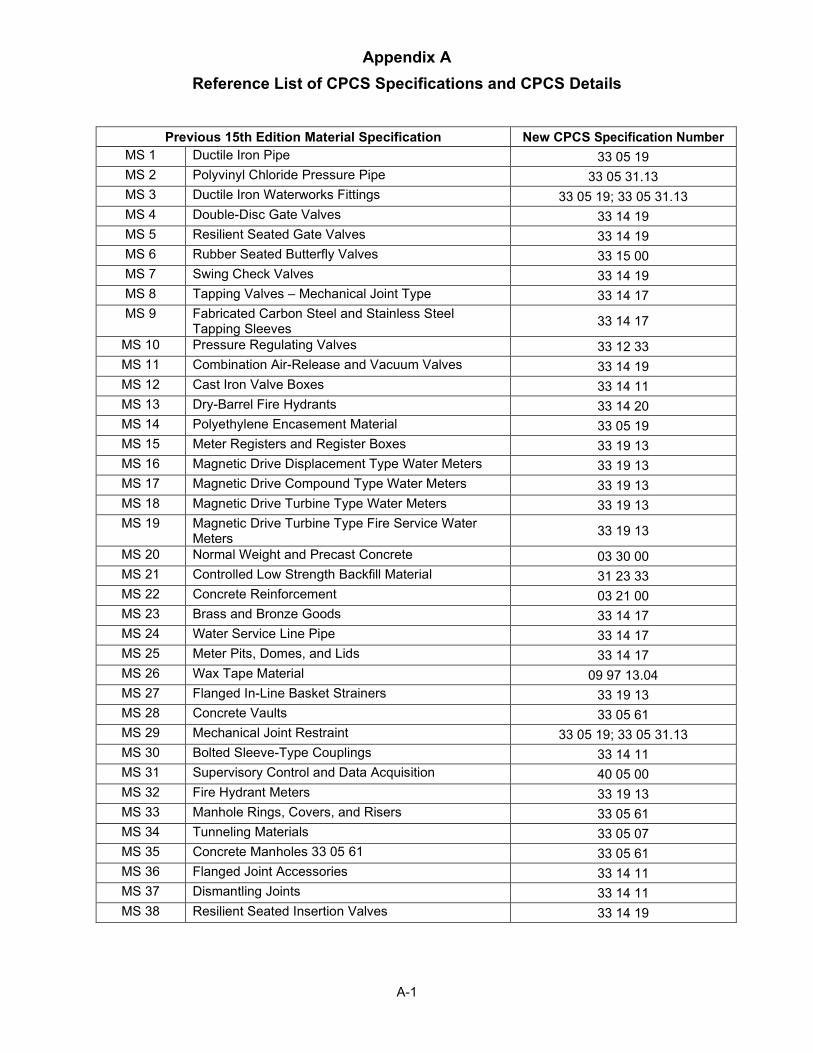
Appendix A Reference List of CPCS Specifications and CPCS Details
A-1
Previous 15th Edition Material Specification New CPCS Specification Number MS 1 Ductile Iron Pipe 33 05 19 MS 2 Polyvinyl Chloride Pressure Pipe 33 05 31.13 MS 3 Ductile Iron Waterworks Fittings 33 05 19; 33 05 31.13 MS 4 Double-Disc Gate Valves 33 14 19 MS 5 Resilient Seated Gate Valves 33 14 19 MS 6 Rubber Seated Butterfly Valves 33 15 00 MS 7 Swing Check Valves 33 14 19 MS 8 Tapping Valves – Mechanical Joint Type 33 14 17 MS 9 Fabricated Carbon Steel and Stainless Steel
Tapping Sleeves 33 14 17
MS 10 Pressure Regulating Valves 33 12 33 MS 11 Combination Air-Release and Vacuum Valves 33 14 19 MS 12 Cast Iron Valve Boxes 33 14 11 MS 13 Dry-Barrel Fire Hydrants 33 14 20 MS 14 Polyethylene Encasement Material 33 05 19 MS 15 Meter Registers and Register Boxes 33 19 13 MS 16 Magnetic Drive Displacement Type Water Meters 33 19 13 MS 17 Magnetic Drive Compound Type Water Meters 33 19 13 MS 18 Magnetic Drive Turbine Type Water Meters 33 19 13 MS 19 Magnetic Drive Turbine Type Fire Service Water
Meters 33 19 13
MS 20 Normal Weight and Precast Concrete 03 30 00 MS 21 Controlled Low Strength Backfill Material 31 23 33 MS 22 Concrete Reinforcement 03 21 00 MS 23 Brass and Bronze Goods 33 14 17 MS 24 Water Service Line Pipe 33 14 17 MS 25 Meter Pits, Domes, and Lids 33 14 17 MS 26 Wax Tape Material 09 97 13.04 MS 27 Flanged In-Line Basket Strainers 33 19 13 MS 28 Concrete Vaults 33 05 61 MS 29 Mechanical Joint Restraint 33 05 19; 33 05 31.13 MS 30 Bolted Sleeve-Type Couplings 33 14 11 MS 31 Supervisory Control and Data Acquisition 40 05 00 MS 32 Fire Hydrant Meters 33 19 13 MS 33 Manhole Rings, Covers, and Risers 33 05 61 MS 34 Tunneling Materials 33 05 07 MS 35 Concrete Manholes 33 05 61 33 05 61 MS 36 Flanged Joint Accessories 33 14 11 MS 37 Dismantling Joints 33 14 11 MS 38 Resilient Seated Insertion Valves 33 14 19
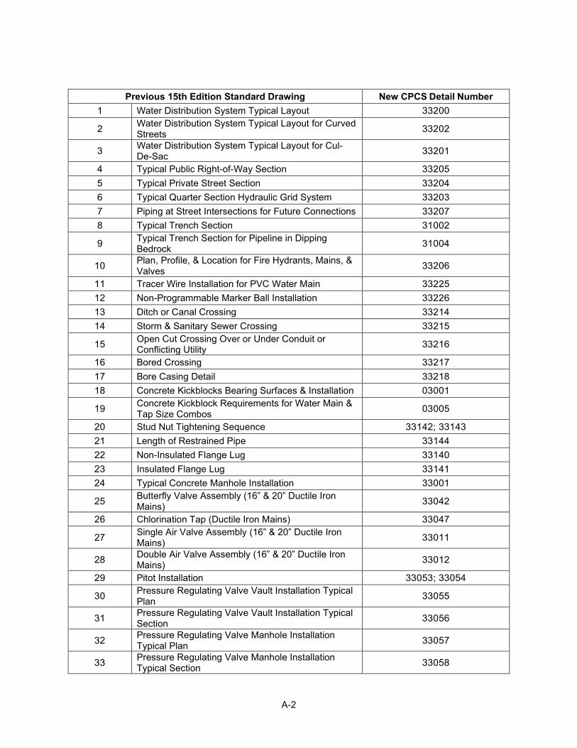
A-2
Previous 15th Edition Standard Drawing New CPCS Detail Number 1 Water Distribution System Typical Layout 33200
2 Water Distribution System Typical Layout for Curved Streets 33202
3 Water Distribution System Typical Layout for Cul-De-Sac 33201
4 Typical Public Right-of-Way Section 33205 5 Typical Private Street Section 33204 6 Typical Quarter Section Hydraulic Grid System 33203 7 Piping at Street Intersections for Future Connections 33207 8 Typical Trench Section 31002
9 Typical Trench Section for Pipeline in Dipping Bedrock 31004
10 Plan, Profile, & Location for Fire Hydrants, Mains, & Valves 33206
11 Tracer Wire Installation for PVC Water Main 33225 12 Non-Programmable Marker Ball Installation 33226 13 Ditch or Canal Crossing 33214 14 Storm & Sanitary Sewer Crossing 33215
15 Open Cut Crossing Over or Under Conduit or Conflicting Utility 33216
16 Bored Crossing 33217 17 Bore Casing Detail 33218 18 Concrete Kickblocks Bearing Surfaces & Installation 03001
19 Concrete Kickblock Requirements for Water Main & Tap Size Combos 03005
20 Stud Nut Tightening Sequence 33142; 33143 21 Length of Restrained Pipe 33144 22 Non-Insulated Flange Lug 33140 23 Insulated Flange Lug 33141 24 Typical Concrete Manhole Installation 33001
25 Butterfly Valve Assembly (16” & 20” Ductile Iron Mains) 33042
26 Chlorination Tap (Ductile Iron Mains) 33047
27 Single Air Valve Assembly (16” & 20” Ductile Iron Mains) 33011
28 Double Air Valve Assembly (16” & 20” Ductile Iron Mains) 33012
29 Pitot Installation 33053; 33054
30 Pressure Regulating Valve Vault Installation Typical Plan 33055
31 Pressure Regulating Valve Vault Installation Typical Section 33056
32 Pressure Regulating Valve Manhole Installation Typical Plan 33057
33 Pressure Regulating Valve Manhole Installation Typical Section 33058
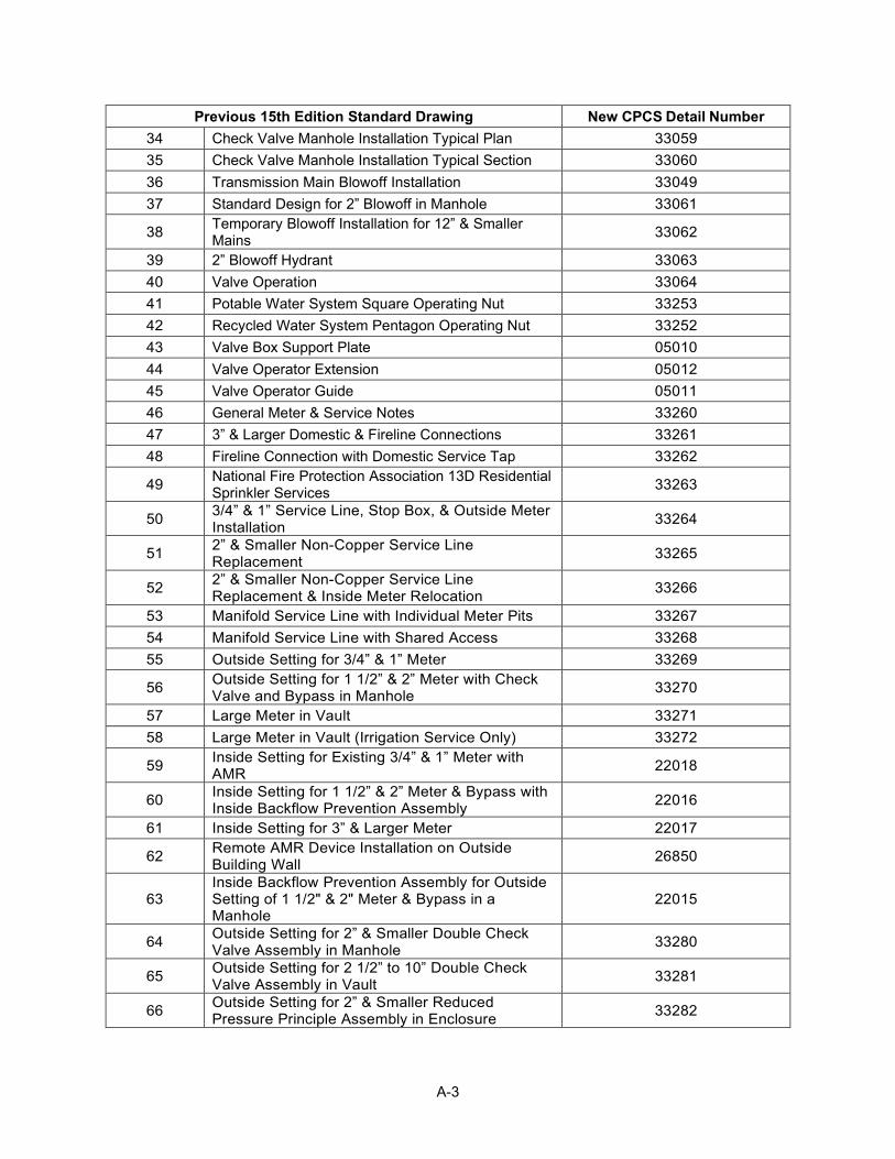
A-3
Previous 15th Edition Standard Drawing New CPCS Detail Number 34 Check Valve Manhole Installation Typical Plan 33059 35 Check Valve Manhole Installation Typical Section 33060 36 Transmission Main Blowoff Installation 33049 37 Standard Design for 2” Blowoff in Manhole 33061
38 Temporary Blowoff Installation for 12” & Smaller Mains 33062
39 2” Blowoff Hydrant 33063 40 Valve Operation 33064 41 Potable Water System Square Operating Nut 33253 42 Recycled Water System Pentagon Operating Nut 33252 43 Valve Box Support Plate 05010 44 Valve Operator Extension 05012 45 Valve Operator Guide 05011 46 General Meter & Service Notes 33260 47 3” & Larger Domestic & Fireline Connections 33261 48 Fireline Connection with Domestic Service Tap 33262
49 National Fire Protection Association 13D Residential Sprinkler Services 33263
50 3/4” & 1” Service Line, Stop Box, & Outside Meter Installation 33264
51 2” & Smaller Non-Copper Service Line Replacement 33265
52 2” & Smaller Non-Copper Service Line Replacement & Inside Meter Relocation 33266
53 Manifold Service Line with Individual Meter Pits 33267 54 Manifold Service Line with Shared Access 33268 55 Outside Setting for 3/4” & 1” Meter 33269
56 Outside Setting for 1 1/2” & 2” Meter with Check Valve and Bypass in Manhole 33270
57 Large Meter in Vault 33271 58 Large Meter in Vault (Irrigation Service Only) 33272
59 Inside Setting for Existing 3/4” & 1” Meter with AMR 22018
60 Inside Setting for 1 1/2” & 2” Meter & Bypass with Inside Backflow Prevention Assembly 22016
61 Inside Setting for 3” & Larger Meter 22017
62 Remote AMR Device Installation on Outside Building Wall 26850
63 Inside Backflow Prevention Assembly for Outside Setting of 1 1/2" & 2" Meter & Bypass in a Manhole
22015
64 Outside Setting for 2” & Smaller Double Check Valve Assembly in Manhole 33280
65 Outside Setting for 2 1/2” to 10” Double Check Valve Assembly in Vault 33281
66 Outside Setting for 2” & Smaller Reduced Pressure Principle Assembly in Enclosure 33282
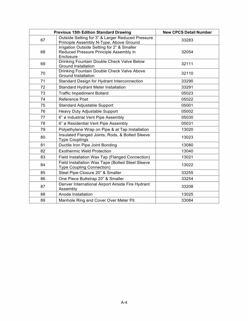
A-4
Previous 15th Edition Standard Drawing New CPCS Detail Number
67 Outside Setting for 3” & Larger Reduced Pressure Principle Assembly N-Type, Above Ground 33283
68 Irrigation Outside Setting for 2” & Smaller Reduced Pressure Principle Assembly in Enclosure
32054
69 Drinking Fountain Double Check Valve Below Ground Installation 32111
70 Drinking Fountain Double Check Valve Above Ground Installation 32110
71 Standard Design for Hydrant Interconnection 33290 72 Standard Hydrant Meter Installation 33291 73 Traffic Impediment Bollard 05023 74 Reference Post 05022 75 Standard Adjustable Support 05001 76 Heavy Duty Adjustable Support 05002 77 6” ø Industrial Vent Pipe Assembly 05030 78 6” ø Residential Vent Pipe Assembly 05031 79 Polyethylene Wrap on Pipe & at Tap Installation 13020
80 Insulated Flanged Joints, Rods, & Bolted Sleeve Type Couplings 13023
81 Ductile Iron Pipe Joint Bonding 13080 82 Exothermic Weld Protection 13040 83 Field Installation Wax Tap (Flanged Connection) 13021
84 Field Installation Wax Tape (Bolted Steel Sleeve Type Coupling Connection) 13022
85 Steel Pipe-Closure 20” & Smaller 33255 86 One Piece Buttstrap 20” & Smaller 33254
87 Denver International Airport Airside Fire Hydrant Assembly 33208
88 Anode Installation 13025 89 Manhole Ring and Cover Over Meter Pit 33084
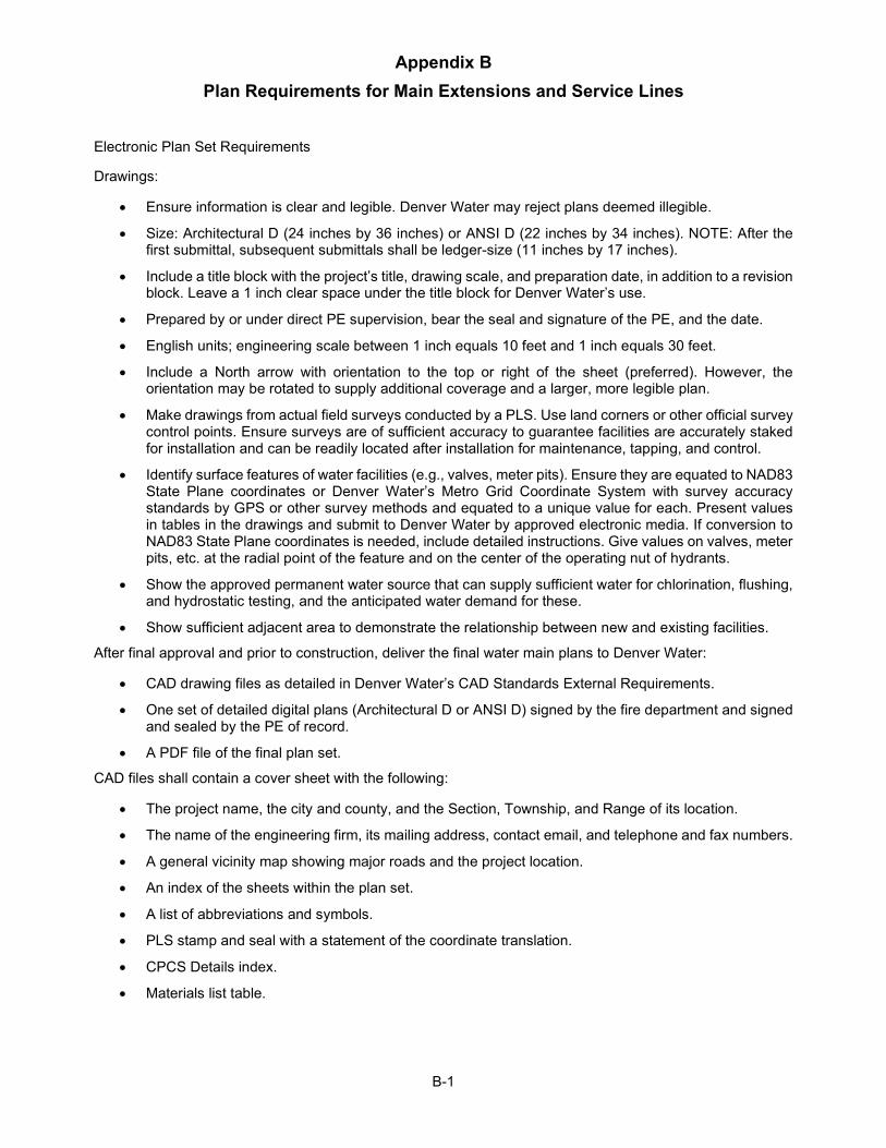
Appendix B Plan Requirements for Main Extensions and Service Lines
B-1
Electronic Plan Set Requirements
Drawings:
• Ensure information is clear and legible. Denver Water may reject plans deemed illegible.
• Size: Architectural D (24 inches by 36 inches) or ANSI D (22 inches by 34 inches). NOTE: After the first submittal, subsequent submittals shall be ledger-size (11 inches by 17 inches).
• Include a title block with the project’s title, drawing scale, and preparation date, in addition to a revision block. Leave a 1 inch clear space under the title block for Denver Water’s use.
• Prepared by or under direct PE supervision, bear the seal and signature of the PE, and the date.
• English units; engineering scale between 1 inch equals 10 feet and 1 inch equals 30 feet.
• Include a North arrow with orientation to the top or right of the sheet (preferred). However, the orientation may be rotated to supply additional coverage and a larger, more legible plan.
• Make drawings from actual field surveys conducted by a PLS. Use land corners or other official survey control points. Ensure surveys are of sufficient accuracy to guarantee facilities are accurately staked for installation and can be readily located after installation for maintenance, tapping, and control.
• Identify surface features of water facilities (e.g., valves, meter pits). Ensure they are equated to NAD83 State Plane coordinates or Denver Water’s Metro Grid Coordinate System with survey accuracy standards by GPS or other survey methods and equated to a unique value for each. Present values in tables in the drawings and submit to Denver Water by approved electronic media. If conversion to NAD83 State Plane coordinates is needed, include detailed instructions. Give values on valves, meter pits, etc. at the radial point of the feature and on the center of the operating nut of hydrants.
• Show the approved permanent water source that can supply sufficient water for chlorination, flushing, and hydrostatic testing, and the anticipated water demand for these.
• Show sufficient adjacent area to demonstrate the relationship between new and existing facilities.
After final approval and prior to construction, deliver the final water main plans to Denver Water:
• CAD drawing files as detailed in Denver Water’s CAD Standards External Requirements.
• One set of detailed digital plans (Architectural D or ANSI D) signed by the fire department and signed and sealed by the PE of record.
• A PDF file of the final plan set.
CAD files shall contain a cover sheet with the following:
• The project name, the city and county, and the Section, Township, and Range of its location.
• The name of the engineering firm, its mailing address, contact email, and telephone and fax numbers.
• A general vicinity map showing major roads and the project location.
• An index of the sheets within the plan set.
• A list of abbreviations and symbols.
• PLS stamp and seal with a statement of the coordinate translation.
• CPCS Details index.
• Materials list table.
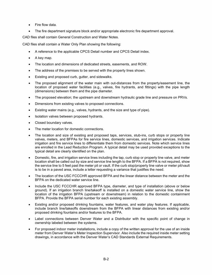
B-2
• Fire flow data.
• The fire department signature block and/or appropriate electronic fire department approval.
CAD files shall contain General Construction and Water Notes.
CAD files shall contain a Water Only Plan showing the following:
• A reference to the applicable CPCS Detail number and CPCS Detail index.
• A key map.
• The location and dimensions of dedicated streets, easements, and ROW.
• The address of the premises to be served with the property lines shown.
• Existing and proposed curb, gutter, and sidewalks.
• The proposed alignment of the water main with out-distances from the property/easement line, the location of proposed water facilities (e.g., valves, fire hydrants, and fittings) with the pipe length (dimensions) between them and the pipe diameter.
• The proposed elevation; the upstream and downstream hydraulic grade line and pressure on PRVs.
• Dimensions from existing valves to proposed connections.
• Existing water mains (e.g., valves, hydrants, and the size and type of pipe).
• Isolation valves between proposed hydrants.
• Closed boundary valves.
• The meter location for domestic connections.
• The location and size of existing and proposed taps, services, stub-ins, curb stops or property line valves, meters, and BFPAs for fire service lines, domestic services, and irrigation services. Indicate irrigation and fire service lines to differentiate them from domestic services. Note which service lines are enrolled in the Lead Reduction Program. A typical detail may be used provided exceptions to the typical detail are clearly identified on the plan.
• Domestic, fire, and irrigation service lines including the tap, curb stop or property line valve, and meter location shall be called out by size and service line length to the BFPA. If a BFPA is not required, show the service line to 5 feet past the meter pit or vault. If the curb stop/property line valve or meter pit/vault is to be in a paved area, include a letter requesting a variance that justifies the need.
• The location of the USC FCCCHR approved BFPA and the linear distance between the meter and the BFPA on the dedicated water service line.
• Include the USC FCCCHR approved BFPA type, diameter, and type of installation (above or below ground). If an irrigation branch line/takeoff is installed on a domestic water service line, show the location of the irrigation BFPA (upstream or downstream) in relation to the domestic containment BFPA. Provide the BFPA serial number for each existing assembly.
• Existing and/or proposed drinking fountains, water features, and water play features. If applicable, include branch line/takeoffs downstream from the BFPA with linear distances from existing and/or proposed drinking fountains and/or features to the BFPA.
• Label connections between Denver Water and a Distributor with the specific point of change in ownership labeled between the systems.
• For proposed indoor meter installations, include a copy of the written approval for the use of an inside meter from Denver Water’s Meter Inspection Supervisor. Also include the required inside meter setting drawings, in accordance with the Denver Water’s CAD Standards External Requirements.
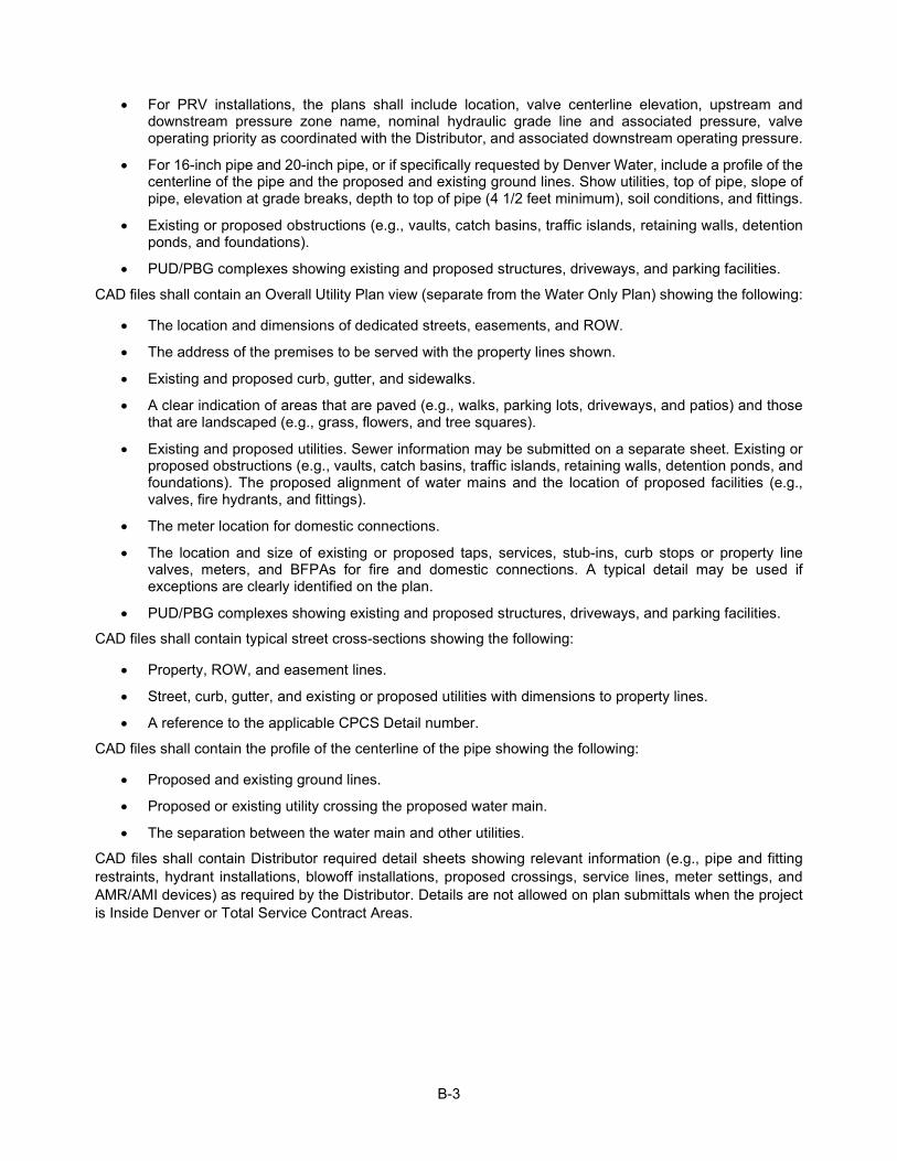
B-3
• For PRV installations, the plans shall include location, valve centerline elevation, upstream and downstream pressure zone name, nominal hydraulic grade line and associated pressure, valve operating priority as coordinated with the Distributor, and associated downstream operating pressure.
• For 16-inch pipe and 20-inch pipe, or if specifically requested by Denver Water, include a profile of the centerline of the pipe and the proposed and existing ground lines. Show utilities, top of pipe, slope of pipe, elevation at grade breaks, depth to top of pipe (4 1/2 feet minimum), soil conditions, and fittings.
• Existing or proposed obstructions (e.g., vaults, catch basins, traffic islands, retaining walls, detention ponds, and foundations).
• PUD/PBG complexes showing existing and proposed structures, driveways, and parking facilities.
CAD files shall contain an Overall Utility Plan view (separate from the Water Only Plan) showing the following:
• The location and dimensions of dedicated streets, easements, and ROW.
• The address of the premises to be served with the property lines shown.
• Existing and proposed curb, gutter, and sidewalks.
• A clear indication of areas that are paved (e.g., walks, parking lots, driveways, and patios) and those that are landscaped (e.g., grass, flowers, and tree squares).
• Existing and proposed utilities. Sewer information may be submitted on a separate sheet. Existing or proposed obstructions (e.g., vaults, catch basins, traffic islands, retaining walls, detention ponds, and foundations). The proposed alignment of water mains and the location of proposed facilities (e.g., valves, fire hydrants, and fittings).
• The meter location for domestic connections.
• The location and size of existing or proposed taps, services, stub-ins, curb stops or property line valves, meters, and BFPAs for fire and domestic connections. A typical detail may be used if exceptions are clearly identified on the plan.
• PUD/PBG complexes showing existing and proposed structures, driveways, and parking facilities.
CAD files shall contain typical street cross-sections showing the following:
• Property, ROW, and easement lines.
• Street, curb, gutter, and existing or proposed utilities with dimensions to property lines.
• A reference to the applicable CPCS Detail number.
CAD files shall contain the profile of the centerline of the pipe showing the following:
• Proposed and existing ground lines.
• Proposed or existing utility crossing the proposed water main.
• The separation between the water main and other utilities.
CAD files shall contain Distributor required detail sheets showing relevant information (e.g., pipe and fitting restraints, hydrant installations, blowoff installations, proposed crossings, service lines, meter settings, and AMR/AMI devices) as required by the Distributor. Details are not allowed on plan submittals when the project is Inside Denver or Total Service Contract Areas.

INTENTIONALLY BLANK
Appendix C Easement Requirements
C-1
Submit the following easement requirements:
Letter request:
• A letter requesting that Denver Water accepts the easement. Indicate the full and legal name of the Property Owner granting the easement, the names and titles of the persons authorized to sign the easement agreement, and those persons who shall verify the identity of the authorized signer, if applicable.
• In the request letter, list Property Owner’s address which will be included in the easement document for all future written notices, requests, demands, information and/or other communication pertaining to the easement agreement.
• If necessary, the Property Owner’s Articles of Organization or Articles of Incorporation shall be provided to determine the name and/or title of the person(s) legally authorized to sign real estate transaction documents. Denver Water may elect to require the proposed grantor to submit an Application for Easement Acceptance in lieu of or in addition to the letter.
Legal description:
• Two copies of the written legal description of the proposed easement area signed and sealed by a PLS. Descriptions not in compliance with the following format will not be accepted.
Exhibit A:
• Size: 8 1/2 inches by 11 inches (letter-size) documents.
• Title: All capitalized and located at the top of the document; referred to as Exhibit A, Legal Description. Caption: The Section number and aliquot part, tract, or government lot thereof; Township; Range; Principal Meridian; County; City or Town, if applicable; and State shall be included. In addition, where appropriate, a Subdivision, Lot, and Block description shall be used. Use any deed along with its corresponding date and recording information when appropriate (i.e., Reception No., Book, and Page).
• Text font: Do not bold face, italicize, or all capitalize text within the description.
• Basis of bearing: The first element in the body of the description. Write descriptions to proceed from the Point of Commencement to the Point of Beginning. The Point of Commencement shall be an aliquot corner or tract corner in the Public Land Survey System with its position marked by an acceptable existing monument. The basis of bearing shall be NAD83 State Plane values.
o Whenever possible, tie parcels to two monuments for which Denver Water has established coordinate values. Such monument locations are compiled from information obtained from various municipal and other entities in the metropolitan area. No claim is made as to the accuracy of the information contained therein. Any submitter who has found discrepancies in the information or has tied to corners not included in the database is encouraged to submit the location and monument description information to keep the database current.
o An acceptable monument shall be in compliance with CRS 38-51-104 of the Rules for Professional Land Surveying Practice 6.4 from the Bylaws and Rules of the State Board of Licensure for Architects, PEs, and PLSs.
o Examples of possible basis of bearing wording: Commencing at the Northeast corner of Section 5, whence the North 1/4 bears (bearing), said
line being the basis of bearing for this description. Commencing at the Northeast corner of Section 5, and considering the North line of said
Northeast 1/4 to bear (bearing), said line forming the basis of bearings for this legal description.
C-2
• Body: Write descriptions with the parcel described in a clockwise direction.
o Point of Beginning (aliquot descriptions excepted), wherever possible, on a legally defined line, and described as being on that line Descriptions of existing lines or bounds being followed or encountered such as, but not limited to, aliquot, ROW, platted lot, and deed lines.
o Courses reported in bearings and distances. o Distances in U. S. Survey feet at ground surface. o Curves identified as being to the left or the right. Curve information shall include radius, central
angle, arc length, bearing to the radius point, chord bearing, and distance. o Curves tangential when creating or describing a new parcel whose lines run independent of
previously identified, legally defined lines unless absolutely necessary. In cases where non- tangential, identify curves as such at the start and the finish, as appropriate.
o Example of possible curve wording: Thence along the arc of a nontangent curve to the left, whose radius point bears (bearing)
from the point of curvature, having a central angle of (angle) and a radius of X feet, and an arc distance of X feet (chord bears [bearing], a distance of X feet).
o When existing (e.g., deed, plat, easement, and ROW) lines are used, include full recording information for the document creating said line (e.g., County, Reception No., Book and Page, date, file, and map).
o Report area in acres to three decimal places followed, parenthetically, by the area in square feet to zero decimal places. Customarily, “more or less” is appended to this square footage value. Report areas for parcels smaller than 1/2 acre in square feet only.
• Approval block: A signature block identifying the surveyor and the name of the surveyor’s company is required in compliance with CRS 38-35-106.5.
• Closure calculations: Include the closure calculation sheet showing the closure as the description is written. Geometric closure of the parcel shall exceed 1 to 20,000.
CAD drawing – a file made in model space, with the title block in paper space, using the layers, linetypes, and settings defined in Denver Water’s CAD Standards External Requirements. Non-compliance with the CAD Standards External Requirements will result in the file being returned to the Applicant.
Include the following:
• Size: Overall 8 1/2 inches by 11 inches (letter-size).
• Title block: Dimensions and text in accordance with the CAD Standards External Requirements.
• Scale: Use an appropriate, recognized civil engineering scale as defined by the CAD Standards External Requirements. Break lines, except in land corners or ties, are not acceptable.
• Tie: Tie parcels to the two nearest recognized land corners (i.e., the section corner, the quarter section corner, and the range point). If the easement is located within a platted subdivision, make a tie to a subdivision corner. Include the basis of bearing statement on the drawing.
• Drawing accuracy: Draw to two decimal places for distance and to one half seconds for bearing.
• Supply descriptions of the monuments set at the ends of the line, which is the basis of the bearing. Include a description of the cap, cap size, and markings and include a PLS number. If markings cannot be reported, include a brief statement on the reason this is the case (e.g., obliterated). Supply a description of the monument the cap is mounted on (e.g., no. 5 rebar, 2-inch pipe) or a reason the information cannot be obtained (e.g., set in concrete).
Title Commitment – covers the waterline easement area only.
Include the following:
• An electronic Microsoft Outlook email file of the Title Commitment from the Title Company including hyperlinks to legible paper copies of the documents referred to in the Schedule B-2 (Exceptions) portion of the Commitment.

C-3
• A plottable drawing or exceptions map depicting the waterline easement and B-2 exceptions. Number exceptions to correlate with those shown on the Commitment for Title Insurance.
• Denver Water may require title insurance to be acquired. The grantor of the easement is responsible for payment of expenses incurred in obtaining title insurance.
• Denver Water, in its sole discretion, may require the licensee or Property Owner to provide an opinion of counsel of Property Owner, on which Denver Water is entitled to rely, to be addressed and delivered to Denver Water stating there are no encumbrances on title to the easement(s) and the grantor of the easement(s) has a good and marketable title.
• Title commitments are required for fire hydrant easements granted adjacent to existing waterline easements or dedicated ROW. Include fire hydrant easements granted as part of a proposed distribution line easement in the Commitment for Title Insurance for the overall waterline easement.
Overall Site Plan – one copy that shows the relationship of the following:
• The proposed water main, easement, and dedicated ROW.
• Existing and proposed utilities with associated utility easements on the site.
• Proposed slopes greater than 20 to 1 and areas of cut/fill greater than 1 foot within the easement area.
• Proposed structures, landscaping, and roadways on the site.
• Cross-sections of private roadways associated with waterline easements and cross-sections of public ROW in which a water main is to be installed.
• Perimeter distances and bearings, or angles, of the overall site and the relationship to the tie corner of the easement.
• Denver Water’s property boundary lines.
• Surrounding ROW limits.
• Proposed construction area.
• Proposed temporary easement area.
• Existing and proposed fencing.
• Denver Water’s nearby facilities.
Subdivision Plat – a copy of a recorded or preliminary subdivision plat or development plan for the area or subdivision the waterline easement is located in, any subdivision plat, or a PUD/PBG plan that directly relates to the easement and depicts property boundaries.

INTENTIONALLY BLANK
Appendix D System Design and Layout for Backflow Prevention and
Cross-Connection Control Program
D-1
Requirements for approved USC FCCCHR BFPA installations based on the degree of hazard:
• Low hazard conditions require DC BFPA.
• High hazard conditions require RP BFPA.
Commercial domestic service line tap:
• Install an approved RP BFPA or DC BFPA on the domestic water service line 5 feet downstream from the meter pit or immediately upon entry into a heated part of the building 5 feet (maximum) from the wall or floor before any connections based on the degree of hazard.
• Protect irrigation branch lines on a domestic service tap by an RP BFPA or PVB located 5 feet downstream from the meter pit immediately upstream or downstream of the domestic containment assembly upon entry into a heated part of the building. Locate PVB a minimum of 12 inches above the highest point of use; do not install PVB where backpressure is present.
• Install drainage in accordance with the manufacturer and the authority having jurisdiction.
Commercial fire service line service tap:
• When installed as a wet pipe system with the use of extinguishing agents or antifreeze, install an approved RP BFPA on the fire service line immediately upon entry into a heated part of the building 5 feet (maximum) from the wall or floor before any connections; see CPCS Details.
• When installed as a wet or dry pipe system without the use of extinguishing agents or antifreeze, install an approved DC BFPA on the fire service line immediately upon entry into a heated part of the building 5 feet (maximum) from the wall or floor before any connections.
• Do not install branch lines and taps on fire service lines downstream from the designated containment BFPA for any purpose other than fire protection. Ensure system branch lines designed with extinguishing agents or antifreeze (loops) are isolated (containment by isolation) by the installation of an approved RP BFPA.
Dedicated irrigation service line tap:
• Install an approved RP BFPA or PVB on the irrigation water service line 5 feet downstream from the meter pit or 10 feet downstream for irrigation installations with the use of a stop and waste valve; do not install branch lines (e.g. hose bibs) upstream of the BFPA. Locate PVBs a minimum of 12-inches above the highest point of use; do not install where backpressure is present.
• Do not install branch lines and taps on dedicated irrigation water service lines for domestic (potable) use.
Commercial drinking fountain domestic service line tap:
• Install an approved DC BFPA on the domestic water service line below ground, 5 feet downstream from the meter pit below ground; above ground, 10 feet downstream from the meter pit with the use of a stop and waste valve in an approved manhole/vault; or above ground, 5 feet downstream from the meter pit.
• Install in accordance with the CPCS Details for services with only a drinking fountain to avoid water quality issues by minimizing the amount of water in the service line between the main and the drinking fountain.
Commercial recycled irrigation service line tap:
• Install an approved RP BFPA on the irrigation water service line 5 feet downstream from the meter pit or 10 feet downstream for irrigation installations with the use of a stop and waste valve if chemical additives are used downstream from the meter, pumps are used downstream from the meter, or the existing or proposed system poses a risk to the integrity of the recycled water system.
D-2
• Ensure the service line is above ground before any connections.
• Do not install branch lines and taps on recycled water service lines for domestic (potable) use.
• Ensure BFPA installations on recycled water service lines are identified as recycled water.
Domestic service line tap on premises where existing irrigation system is converted to recycled water service:
• Install an approved DC BFPA on the domestic water service line 5 feet downstream from the meter pit below ground in an approved manhole/vault or above ground before any connections.
Multi-family domestic service line tap:
• Install an approved RP BFPA or DC BFPA acting as containment if the premises has a fire protection system or the premises has a common boiler. Use of Containment by Isolation must be approved by Denver Water’s Cross Connection Control group.
• Install the BFPA on the domestic water service line 5 feet downstream from the meter pit or immediately upon entry into a heated part of the building 5 feet (maximum) from the wall or floor before any connections based on the degree of hazard.
• Install drainage in accordance with the manufacturer’s and the authority having jurisdiction’s requirements in the event of a relief valve discharge.
Domestic service line tap on the premises with a Dual Water Supply Agreement:
• Install an approved DC BFPA on the domestic water service line 5 feet downstream from the meter pit below ground in an approved manhole/vault or immediately upon entry into a heated part of the building 5 feet (maximum) from the wall or floor before any connections. It is at the sole discretion of Denver Water’s Cross Connection Control group to determine if the existing dual water supply poses a high risk to Denver Water’s potable distribution system. The installation of a RP BFPA may be required 5 feet downstream from the meter pit in an above ground, heated enclosure before any connections. A RP BFPA may be required at point of use to high hazard system as determined by Denver Water’s Cross Connection Control group.
Domestic Service Line Tap with NFPA 13D Fire Sprinklers
• All residential/multi-family fire suppression systems and associated BFPA shall be approved by Denver Water. NFPA 13D requirements for individual units within a multi-family building shall be approved in writing by the local fire dept.
• Multipurpose piping type systems shall meet NFPA 13D requirements. DC BFPA or RP BFPA installation may not be required depending on water turnover frequency. Denver Water’s Cross Connection Control group will determine the type of BFPA based on the degree of hazard.
• Where chemical additives are used in a NFPA 13D system, install an approved USC FCCCHR RP BFPA on the fire sprinkler branch line.
Examples of commercial properties supplied with recycled water or dual water sources that require a RP BFPA or DC BFPA:
• Where a recycled water irrigation system is designed to inject chemical additives and the use of pumps installed downstream from the meter and/or the proposed irrigation system poses a risk to the integrity of the recycled water system, install an approved USC FCCCHR RP BFPA on the designated service line to the premises 5 feet downstream from the meter pit or 10 feet downstream with the use of a stop and waste valve.
• Where dual water is used for irrigation on a commercial, multi-family, or residential premises, install an approved USC FCCCHR BFPA 5 feet downstream from the meter pit on the domestic water service line. The Denver Water’s Cross Connection Control group will determine type of BFPA based on the degree of hazard encountered downstream of the meter.
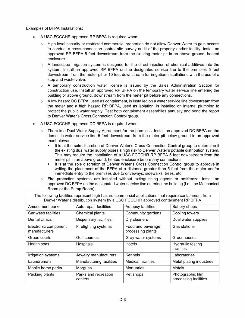
D-3
Examples of BFPA Installations:
• A USC FCCCHR approved RP BFPA is required when:
o High level security or restricted commercial properties do not allow Denver Water to gain access to conduct a cross-connection control site survey audit of the property and/or facility. Install an approved RP BFPA 5 feet downstream from the existing meter pit in an above ground, heated enclosure.
o A landscape irrigation system is designed for the direct injection of chemical additives into the system. Install an approved RP BFPA on the designated service line to the premises 5 feet downstream from the meter pit or 10 feet downstream for irrigation installations with the use of a stop and waste valve.
o A temporary construction water license is issued by the Sales Administration Section for construction use. Install an approved RP BFPA on the temporary water service line entering the building or above ground, downstream from the meter pit before any connections.
o A low hazard DC BFPA, used as containment, is installed on a water service line downstream from the meter and a high hazard RP BFPA, used as isolation, is installed on internal plumbing to protect the public water supply. Test both containment assemblies annually and send the report to Denver Water’s Cross Connection Control group.
• A USC FCCCHR approved DC BFPA is required when:
o There is a Dual Water Supply Agreement for the premises. Install an approved DC BFPA on the domestic water service line 5 feet downstream from the meter pit below ground in an approved manhole/vault. It is at the sole discretion of Denver Water’s Cross Connection Control group to determine if
the existing dual water supply poses a high risk to Denver Water’s potable distribution system. This may require the installation of a USC FCCCHR RP BFPA 5 feet downstream from the meter pit in an above ground, heated enclosure before any connections.
It is at the sole discretion of Denver Water’s Cross Connection Control group to approve in writing the placement of the BFPA at a distance greater than 5 feet from the meter and/or immediate entry to the premises due to driveways, sidewalks, trees, etc.
o Fire protection systems are installed without extinguishing agents or antifreeze. Install an approved DC BFPA on the designated water service line entering the building (i.e., the Mechanical Room or the Pump Room).
The following facilities represent high hazard commercial applications that require containment from Denver Water’s distribution system by a USC FCCCHR approved containment RP BFPA
Amusement parks Auto repair facilities Autopsy facilities Battery shops Car wash facilities Chemical plants Community gardens Cooling towers Dental clinics Dispensary facilities Dry cleaners Dual water supplies
Electronic component manufacturers
Firefighting systems Food and beverage processing plants
Gas stations
Green courts Golf courses Gray water systems Greenhouses Health spas Hospitals Hotels Hydraulic testing
facilities Irrigation systems Jewelry manufacturers Kennels Laboratories Laundromats Manufacturing facilities Medical facilities Metal plating industries Mobile home parks Morgues Mortuaries Motels Packing plants Parks and recreation
centers Pet shops Photographic film
processing facilities
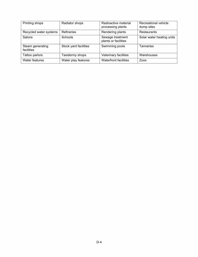
D-4
Printing shops Radiator shops Radioactive material processing plants
Recreational vehicle dump sites
Recycled water systems Refineries Rendering plants Restaurants Salons Schools Sewage treatment
plants or facilities Solar water heating units
Steam generating facilities
Stock yard facilities Swimming pools Tanneries
Tattoo parlors Taxidermy shops Veterinary facilities Warehouses Water features Water play features Waterfront facilities Zoos
Appendix E District Ownership and Operations
E-1
Where a direct connection exists from a conduit owned by Denver Water to a District-owned distribution main, the tapping valve or otherwise first valve off the conduit is owned and operated by Denver Water:
• Unless otherwise agreed to in writing between Denver Water and the District, Denver Water owns up to the downstream side of the tapping valve or otherwise first valve located on the District distribution main. Denver Water is responsible for maintenance of the valve and the water main from the conduit to the valve. The District is responsible for maintenance downstream of the valve.
• Operating Procedures:
o Under normal operating procedures when a planned outage is required, Denver Water will contact the District 48 hours in advance of making any necessary adjustments to the operation of the valve.
o In the event of a planned outage by Denver Water of a conduit facility, Denver Water will notify the District as soon as possible in the planning process to create a coordinated outage plan to ensure both parties’ needs are addressed.
o Under emergency operating procedures (an unplanned outage), Denver Water will notify the District immediately upon operation of the valve and will re-notify the District upon reactivation to normal operating status.
o The District is authorized to operate this valve only in emergency situations. The District shall notify Denver Water Load Control at 303-628-6801 immediately upon operation of the valve. (Personnel are always available.) At the time of notification, the District may also request authorization to reactivate the valve when the situation is resolved, with only a follow-up notification to Denver Water. Otherwise, the District shall notify Denver Water to reactivate the valve to normal service.
Where a direct connection exists from a District-owned distribution main to a Denver Water or Total Service owned distribution main:
• Unless otherwise agreed to in writing between Denver Water and the District, the Denver Water ownership and operation/maintenance responsibilities are limited to the Denver Water/Total Service side of the tapping or first isolation valve on the District distribution main. This includes the “T” connection and any associated distribution main leading up to the valve. The District is responsible for maintenance of the tapping or first isolation valve and the District side distribution main. Where a valve is not available to set as a point of transition, another definable feature, typically a tee fitting, may be substituted as designated by agreement.
• Operating Procedures:
o Under normal operating procedures, the District may operate their distribution valve without notifying Denver Water. If operation of the valve disables service to a Denver Water/Total Service main, the District shall notify Denver Water Load Control at 303-628-6801 immediately upon detection of the problem. (Personnel are always available.) When the situation is resolved and the valve is restored to normal operation, the District shall notify Denver Water and indicate restoration of full service.
o Denver Water is authorized to operate the valve only in emergency situations. Denver Water will notify District personnel immediately upon operation of the valve. At the time of notification, Denver Water may also request authorization to reactivate the valve when the emergency situation is resolved, with only a follow-up notification to the District. Otherwise, when the emergency situation is resolved, Denver Water shall notify the District to reactivate the valve to normal service.
o These same procedures apply to the nearest valve on either side of a defined ownership transition point when that transition point is not defined at a valve.
E-2
Where a direct connection exists from a Denver Water or Total Service owned distribution main to a District owned distribution main:
• Unless otherwise agreed to in writing between Denver Water and the District, District ownership and operation/maintenance responsibilities are limited to the District side of the tapping or first isolation valve on the Denver Water/Total Service distribution main. This includes the “T” connection and any associated distribution main leading up to the valve. Denver Water is responsible for maintenance of the tapping or first isolation valve and the Denver Water/Total Service distribution main. Where a valve is not available to set as a point transition, another definable feature, most typically a “T” fitting, may be substituted as designated by agreement.
• Operating Procedures:
o Under normal operating procedures, Denver Water may operate their distribution valve without any notification to the District. If operation of the valve disables service to a District main, Denver Water will notify District personnel immediately upon detection of the problem. When the situation is resolved and the valve is restored to normal operation by Denver Water, a follow-up notification will be made to the District indicating restoration of full service.
o The District is authorized to operate the valve only in emergency situations. The District shall notify Denver Water Load Control at 303-628-6801 immediately upon operation of the valve. (Personnel are always available.) At the time of notification, the District may also request authorization to reactivate the valve when the emergency situation is resolved, with only a follow-up notification to Denver Water. Otherwise, when the emergency situation is resolved, the District shall notify Denver Water to reactivate the valve to normal service.
o These same procedures apply to the nearest valve on either side of a defined ownership transition point when that transition point is not defined at a valve.
PRV Ownership and Operation:
• PRVs regulate pressure to allow flow from a higher pressure facility (conduit) or pressure zone (distribution main) to a lower pressure facility or pressure zone. District connections to Denver Water or Total Service systems may affect customers or operations; therefore, PRV ownership and operation shall be addressed by agreement.
• PRV Classification:
o District Owned, Maintained, and Operated: Where PRV operations affect only the Total Service District wherein they are located or have only a minimal potential for impact to Denver Water or Total Service customers or operations, the District shall own, operate, and maintain the PRVs.
o Denver Water Owned, Maintained, and Operated: Where PRV operations affect only the Denver Water or Total Service District customers wherein they are located, or are located within and supply the District with a greater potential for impact to Denver Water or Total Service customers or operations, Denver Water will own, operate, and maintain the PRVs. This includes PRVs that contain Denver Water telemetry as Denver Water requires continuous access to maintain and operate this equipment.
o District Owned and Maintained with Cooperative Operation: Where PRVs are located within and supply the Total Service District but through interconnects to Denver Water or Total Service systems may have a larger impact on Denver Water or Total Service customers or operations, the District shall own, operate, and maintain the PRV. Both parties will cooperatively determine and agree to a downstream setting pressure that integrates the District operation into the overall operation of Denver Water’s system.
• Operational Priority:
o Priority 1: The PRV is considered primary and set to a downstream operating pressure equivalent to the nominal static hydraulic gradient for the pressure zone being fed. These PRVs operate consistently in normal conditions.
E-3
o Priority 2: The PRV is considered a secondary supply and is set to a downstream pressure equivalent to 5 psi below the nominal static hydraulic gradient for the pressure zone being fed. These PRVs operate under higher demand conditions.
o Priority 3: The PRV is considered a tertiary supply and is set to a downstream pressure equivalent to 10 psi below the nominal static hydraulic gradient for the pressure zone being fed. These PRVs operate under emergency and fire flow conditions.
• New Facilities and Operations:
o For new connections between District and Denver Water facilities, as indicated in the New Development or the District Capital Improvement plan review process, plans shall indicate the point of change in ownership using the rules established for interconnections between transmission and distribution facilities. Information shall be reviewed and approved during the plan review process.
o For new PRVs, as indicated on Development or Capital Improvement plans, plans shall indicate the PRV Classification and Operational Priority, including the associated downstream operating pressure. Plans shall also include any specific location name to be used (other than the intersection); valve centerline elevation; upstream and downstream pressure zone name and nominal hydraulic grade line and associated pressure. Information shall be reviewed and approved during the plan review process.
o For new closed boundary valves, as indicated on Development or Capital Improvement plans, placement shall be shown. Information shall be reviewed and approved during the plan review process.
• Existing Facilities and Operations:
o Proposed changes to PRV operation not strictly under the District’s autonomous ownership and operation shall be discussed and approved in writing by both the District and Denver Water prior to implementation.
o Proposed changes to pressure zone boundaries and the associated closed boundary valves shall be discussed and approved in writing by both the District and Denver Water prior to implementation.

INTENTIONALLY BLANK
Appendix F Pumping Facilities
F-1
Design pump stations that receive water from Denver Water’s system to meet the following criteria:
• Secured against unauthorized entry.
• Located and kept in a manner that allows for easy and safe access for maintenance and inspection.
• Mechanical forced ventilation at a rate of no less than 6 air changes/hour. Design intake and exhaust vents to prevent the entry of small animals and insects, include a filter rack. Ensure vents have motorized dampers to prevent air infiltration into the vault when the ventilation system is not in operation. Ensure fans, ductwork, and damper materials are constructed of aluminum and/or PVC. Vent stacks may be steel gooseneck type or aluminum tiered caps depending on architectural requirements.
• Heating, cooling, and humidity controls provide for the safe, dry, and efficient operation of piping, pumping equipment, instrumentation, and alarms.
• Pumping capacity sized to provide adequate flow coverage for minimum demands up to the maximum requirements as determined by fire demand, maximum day demand, maximum hour demand, or replenishment, whichever is greater.
• A means for measuring flow on pump discharge headers.
• Corrosion protection for underground steel and iron.
• Code compliant plumbing systems, include floor drains, sump pump systems, and wash-down service water systems. Pump and valve packaging leakage piped to the floor drain or sump pump system.
• Local and remote electronic telemetry equipment of the type specified by Denver Water for monitoring the discharge pressure and confirming the pump motor status.
• A frost proof gravity line or sump pump for pump station drainage to the local sanitary sewer. A check valve, p-trap, and cleanout provided on the sump discharge line.
• A means to prevent water from backing up into the pump station from other sources (e.g., installing a check valve on the drain line).
• Standardized equipment to allow interchangeability with other equipment.
• Selection of pumping units and associated components that prevent pressure surges. Ensure the suitability, flexibility, and adaptability of the units to the hydraulic conditions of the system from which water is taken and the system into which it is pumped.
• The horsepower rating of each pump motor can continuously carry the maximum load that may possibly develop (non-overloading at any point on the pump curve) without exceeding the motor nameplate rating and without using the service factor.
• Locate pumps to receive positive suction head and meet the manufacturer's required net positive suction head requirements.
• Steel pump and motor bases are level, coplanar, free from internal stress, and have internal voids filled with epoxy grout above a steel reinforced concrete base.
• DI or steel piping designed according to AWWA standards with adequate couplings for equipment, SST piping supports, and drains.
• Mechanical design, equipment selection, and installation practices approved by Denver Water. Drawings and information describe the system curve and pump curve interactions, pump operating conditions and associated efficiencies, pumping equipment sizing and features, valve/actuator sizing and operating requirements, and HVAC design loads, ductwork sizing, and equipment selections. Include the certified manufacturer’s pump performance curves.
F-2
• Electrical design, equipment selection, and installation practices approved by Denver Water. Show the power system, switchgear, protective devices, feeder panels, and wiring and motor controllers along with sizing, fault current, and protective device coordination calculations on drawings. The latest edition of the NEC, OSHA's Design Safety Standards for Electrical Systems, and applicable ANSI/IEEE Standards set the minimum standards to which the design, equipment, and installation shall conform. Denver Water may set higher standards for safety or reliability purposes.
• Slow-closing regulating and/or check valves on pumps to minimize water hammer.
• Ample clearance between equipment for operation and maintenance.
• Electrical outlets and lighting on walls in the pump room.
Denver Water may require the following conditional design criteria depending on the function and the location of the pump station:
• Aesthetically pleasing building architecture compatible with the surrounding area.
• Attractive, water-conserving landscaping.
• Exterior and interior lighting.
• Access and parking for vehicles on-site.
• Fencing for securing the area around the pump station and transformers.
• Space for the future addition of pumps and piping.
• A means to lift heavy equipment (e.g., a bridge crane or access for a boom crane).
• Variable speed or throttling control with the appropriate discharge valves and controls.
• An emergency power supply for telemetry, lights, a drain sump pump, and other necessary items.
• Surge control.
• Installation of guard valves on each side of the pumping unit.
• Systems capable of supplying adequate fire protection during power outages.
• Resistance temperature detectors in stator windings of pump motors for remote alarming in case of overheating.
• A spare pump for backup capability.
• Pump and motor bearing high-temperature sensors for remote alarming and lock out relays to shut down the pump and the motor in case of bearing overheating.
• Aquastat over the temperature shutdown switch on the pump to protect the pump from overheating. The aquastat shall not contain mercury.
• Reduced voltage motor starters, depending on the motor size and the electric power system.
• Dual transformers cross-connected with a tie breaker and separately switched for isolation.
• A remote control for pumps, gas engines, and filling valves (start – stop – position discharge valve).
• Local and remote instrumentation for monitoring discharge valve positions; discharge header pressure and flow; reservoir level, if applicable; upstream pressure, if applicable; suction header pressure, if applicable; pump status (on-off); gas engine standby generator status (on-off); total kW demand (station).
• Provide remote and local sensors and alarms to detect water on the floor; bearing high-temperature for each pumping unit; motor windings high-temperature for each pumping unit; pump building door intrusion; high and low room temperature; electrical ground fault; low accumulator pressure, if applicable; power failure; high and low reservoir levels, if applicable; fire and/or smoke.
Appendix G SCADA Standards and Practices
G-1
SCADA equipment and instruments shall be in accordance with these Standards and are subject to Denver Water’s approval. Construct and install equipment in accordance with plans and specifications submitted to and approved in writing by Denver Water prior to the beginning of the system’s construction. Prepare plans and specifications using ISA industry standard electrical/electronic, instrumentation symbols, and drafting practices. Changes in design or equipment specifications on approved plans need to be re-approved by Denver Water before the changes are implemented in the system. Use only plans approved by Denver Water’s Network and Industrial Controls Systems. For systems requiring 15 I/O points or more in any combination of analog and digital points and containing no more than one closed loop control loop, the following documentation is required:
• The control viewpoint containing an overview of how the system is to operate. Include a listing of digital and analog I/O points, control loop descriptions, set points, normal operating ranges, alarm points operating sequence, and operator interface information. Use the control viewpoint for check-out, startup, system revisions, and maintenance.
• An equipment/instrument list that includes equipment tags to be used throughout drawings (ISA Standards), the manufacturer and model number, and a concise description of the manufacturer’s specifications as applied to the requirements of the process manufacturer’s cut-sheets and literature. The Network and Industrial Controls Systems Section will review equipment submitted for approval and use the list as a cross-reference guide for the drawing package.
• An I&C P&ID Typical that shows the equipment/instrument interconnections in block form using ISA Standards. Use the nomenclature established on the equipment list. The flow of signals shall move from left to right across the drawings. Show normal operating points, signal levels, frequencies, and instrument adjustments. Use P&IDs for design and installation. Ensure P&IDs are in accordance with the Engineering Standards; subject to Denver Water’s approval.
• An I&C Cabinet Layout Typical that includes layouts for operating stations, push-button stations, terminal boxes, control equipment enclosures, etc. to clearly show the location of panel-mounted telemetry/control system components. Use panel layout drawings for fabrication, installation, and maintenance. Ensure I&C Cabinets are in accordance with the Engineering Standards; subject to Denver Water’s approval.
• An I&C Detail and Schedules Typical that includes parts/instrument material schedule for equipment located in the enclosure, nameplate schedule, panel cut-out details, etc. Use these drawings for fabrication, installation, and maintenance. Ensure I&C Detail and Schedules are in accordance with the Engineering Standards; subject to Denver Water’s approval.
• An I&C Ladder Diagram Typical that shows the necessary electrical connections to equipment in schematic form and ladder logic, if applicable. Include any set points or other information pertinent to the installation of the system. Show information regarding power requirements including the main power feed capacity, voltage and origin, and transformer and power supply available load and operating voltage. Ensure I&C drawings are in accordance with the Engineering Standards; subject to Denver Water’s approval.
• Wiring details that include wire numbers, colors, and sizes along with terminal numbers/names for terminals, and whether off a terminal strip or instrument terminal. Use concise nomenclature for equipment functions. Use schematics for fabrication, installation, and maintenance. Ensure wiring details are in accordance with the Engineering Standards; subject to Denver Water’s approval.
• Software documentation in the form of a hardcopy printout and an electronic copy of the completed program.
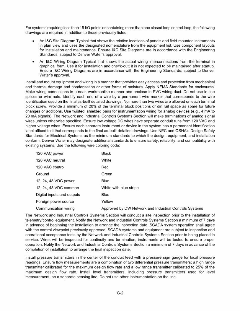
G-2
For systems requiring less than 15 I/O points or containing more than one closed loop control loop, the following drawings are required in addition to those previously listed:
• An I&C Site Diagram Typical that shows the relative locations of panels and field-mounted instruments in plan view and uses the designated nomenclature from the equipment list. Use component layouts for installation and maintenance. Ensure I&C Site Diagrams are in accordance with the Engineering Standards; subject to Denver Water’s approval.
• An I&C Wiring Diagram Typical that shows the actual wiring interconnections from the terminal in graphical form. Use it for installation and check-out; it is not expected to be maintained after startup. Ensure I&C Wiring Diagrams are in accordance with the Engineering Standards; subject to Denver Water’s approval.
Install and mount equipment and wiring in a manner that provides easy access and protection from mechanical and thermal damage and condensation or other forms of moisture. Apply NEMA Standards for enclosures. Make wiring connections in a neat, workmanlike manner and enclose in PVC wiring duct. Do not use in-line splices or wire nuts. Identify each end of a wire by a permanent wire marker that corresponds to the wire identification used on the final as-built detailed drawings. No more than two wires are allowed on each terminal block screw. Provide a minimum of 20% of the terminal block positions or din rail space as spare for future changes or additions. Use twisted, shielded pairs for instrumentation wiring for analog devices (e.g., 4 mA to 20 mA signals). The Network and Industrial Controls Systems Section will make terminations of analog signal wires unless otherwise specified. Ensure low voltage DC wires have separate conduit runs from 120 VAC and higher voltage wires. Ensure each separate instrument or device in the system has a permanent identification label affixed to it that corresponds to the final as-built detailed drawings. Use NEC and OSHA’s Design Safety Standards for Electrical Systems as the minimum standards to which the design, equipment, and installation conform. Denver Water may designate additional standards to ensure safety, reliability, and compatibility with existing systems. Use the following wire coloring code:
120 VAC power Black
120 VAC neutral White
120 VAC control Red
Ground Green
12, 24, 48 VDC power Blue
12, 24, 48 VDC common White with blue stripe
Digital inputs and outputs Blue
Foreign power source Yellow
Communication wiring Approved by DW Network and Industrial Controls Systems
The Network and Industrial Controls Systems Section will conduct a site inspection prior to the installation of telemetry/control equipment. Notify the Network and Industrial Controls Systems Section a minimum of 7 days in advance of beginning the installation to arrange the inspection date. SCADA system operation shall agree with the control viewpoint previously approved. SCADA systems and equipment are subject to inspection and operational acceptance tests by the Network and Industrial Controls Systems Section prior to being placed in service. Wires will be inspected for continuity and termination; instruments will be tested to ensure proper operation. Notify the Network and Industrial Controls Systems Section a minimum of 7 days in advance of the completion of installation to arrange the final inspection date.
Install pressure transmitters in the center of the conduit teed with a pressure sign gauge for local pressure readings. Ensure flow measurements are a combination of two differential pressure transmitters: a high range transmitter calibrated for the maximum design flow rate and a low range transmitter calibrated to 25% of the maximum design flow rate. Install level transmitters, including pressure transmitters used for level measurement, on a separate sensing line. Do not use other instrumentation on the line.
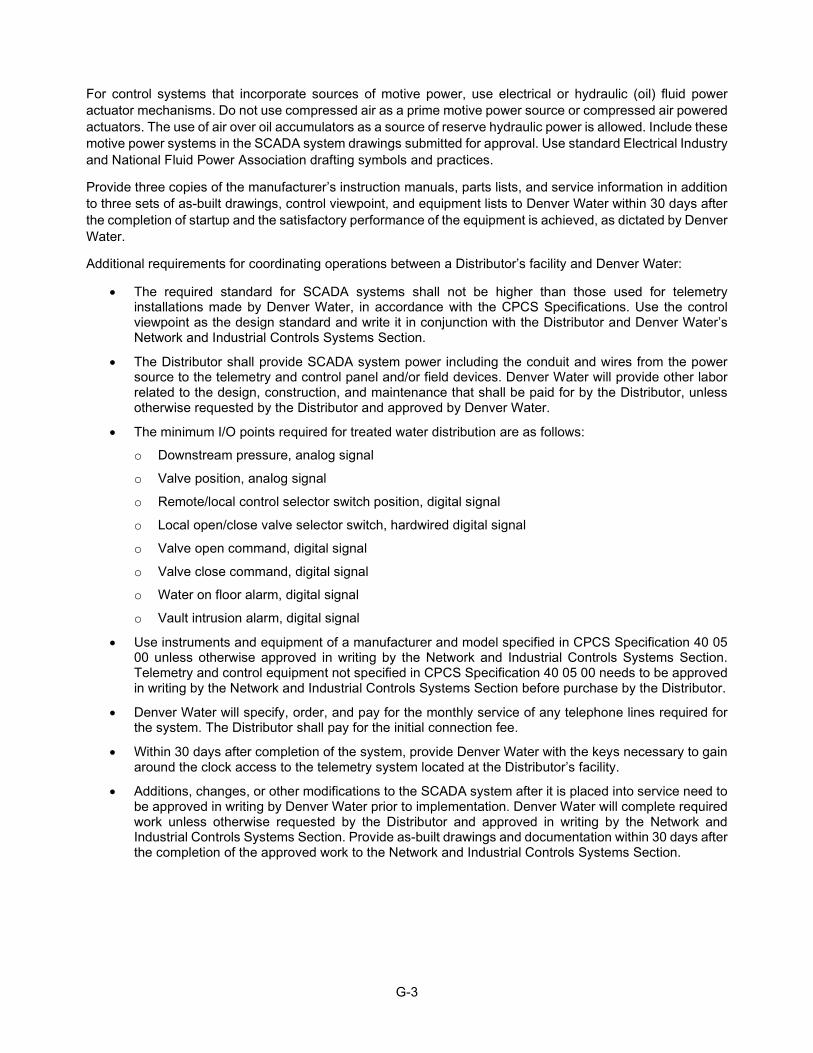
G-3
For control systems that incorporate sources of motive power, use electrical or hydraulic (oil) fluid power actuator mechanisms. Do not use compressed air as a prime motive power source or compressed air powered actuators. The use of air over oil accumulators as a source of reserve hydraulic power is allowed. Include these motive power systems in the SCADA system drawings submitted for approval. Use standard Electrical Industry and National Fluid Power Association drafting symbols and practices.
Provide three copies of the manufacturer’s instruction manuals, parts lists, and service information in addition to three sets of as-built drawings, control viewpoint, and equipment lists to Denver Water within 30 days after the completion of startup and the satisfactory performance of the equipment is achieved, as dictated by Denver Water.
Additional requirements for coordinating operations between a Distributor’s facility and Denver Water:
• The required standard for SCADA systems shall not be higher than those used for telemetry installations made by Denver Water, in accordance with the CPCS Specifications. Use the control viewpoint as the design standard and write it in conjunction with the Distributor and Denver Water’s Network and Industrial Controls Systems Section.
• The Distributor shall provide SCADA system power including the conduit and wires from the power source to the telemetry and control panel and/or field devices. Denver Water will provide other labor related to the design, construction, and maintenance that shall be paid for by the Distributor, unless otherwise requested by the Distributor and approved by Denver Water.
• The minimum I/O points required for treated water distribution are as follows:
o Downstream pressure, analog signal
o Valve position, analog signal
o Remote/local control selector switch position, digital signal
o Local open/close valve selector switch, hardwired digital signal
o Valve open command, digital signal
o Valve close command, digital signal
o Water on floor alarm, digital signal
o Vault intrusion alarm, digital signal
• Use instruments and equipment of a manufacturer and model specified in CPCS Specification 40 05 00 unless otherwise approved in writing by the Network and Industrial Controls Systems Section. Telemetry and control equipment not specified in CPCS Specification 40 05 00 needs to be approved in writing by the Network and Industrial Controls Systems Section before purchase by the Distributor.
• Denver Water will specify, order, and pay for the monthly service of any telephone lines required for the system. The Distributor shall pay for the initial connection fee.
• Within 30 days after completion of the system, provide Denver Water with the keys necessary to gain around the clock access to the telemetry system located at the Distributor’s facility.
• Additions, changes, or other modifications to the SCADA system after it is placed into service need to be approved in writing by Denver Water prior to implementation. Denver Water will complete required work unless otherwise requested by the Distributor and approved in writing by the Network and Industrial Controls Systems Section. Provide as-built drawings and documentation within 30 days after the completion of the approved work to the Network and Industrial Controls Systems Section.

INTENTIONALLY BLANK
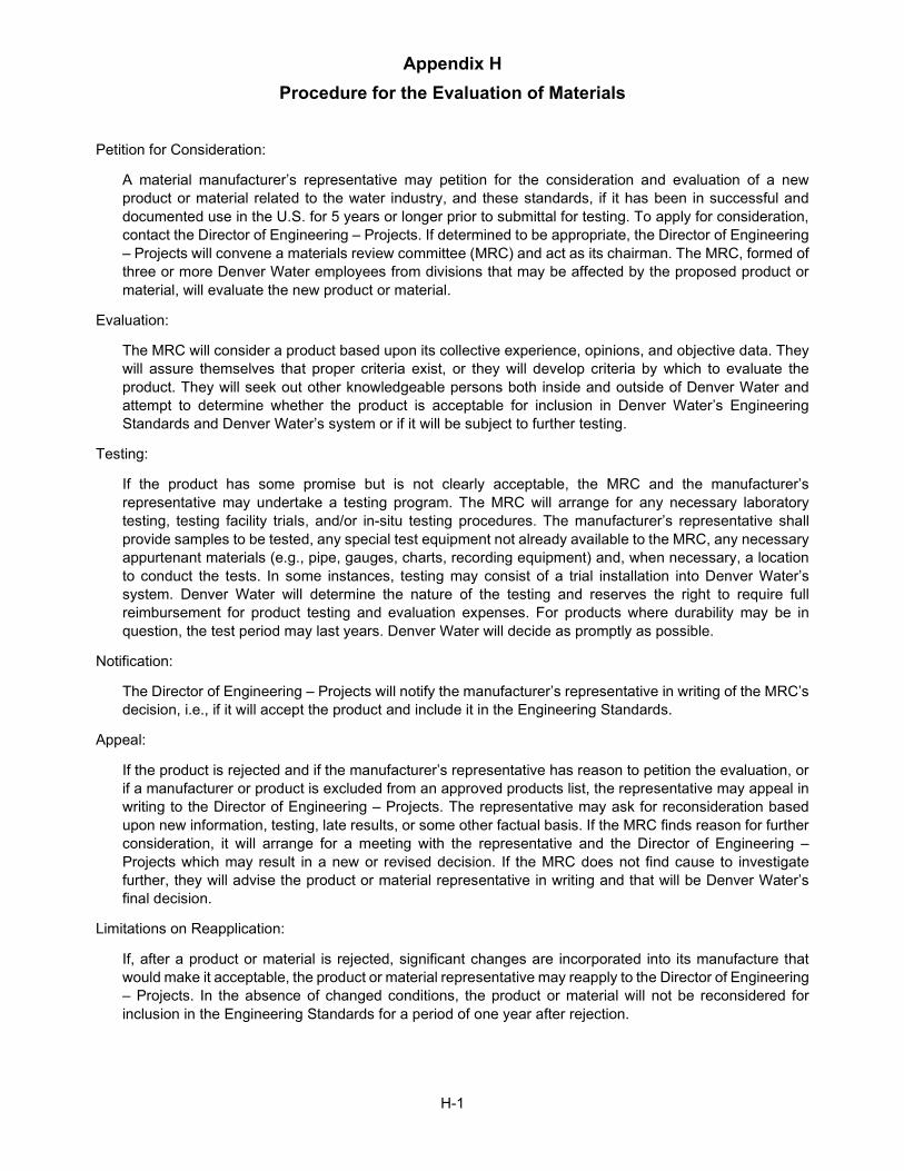
Appendix H Procedure for the Evaluation of Materials
H-1
Petition for Consideration:
A material manufacturer’s representative may petition for the consideration and evaluation of a new product or material related to the water industry, and these standards, if it has been in successful and documented use in the U.S. for 5 years or longer prior to submittal for testing. To apply for consideration, contact the Director of Engineering – Projects. If determined to be appropriate, the Director of Engineering – Projects will convene a materials review committee (MRC) and act as its chairman. The MRC, formed of three or more Denver Water employees from divisions that may be affected by the proposed product or material, will evaluate the new product or material.
Evaluation:
The MRC will consider a product based upon its collective experience, opinions, and objective data. They will assure themselves that proper criteria exist, or they will develop criteria by which to evaluate the product. They will seek out other knowledgeable persons both inside and outside of Denver Water and attempt to determine whether the product is acceptable for inclusion in Denver Water’s Engineering Standards and Denver Water’s system or if it will be subject to further testing.
Testing:
If the product has some promise but is not clearly acceptable, the MRC and the manufacturer’s representative may undertake a testing program. The MRC will arrange for any necessary laboratory testing, testing facility trials, and/or in-situ testing procedures. The manufacturer’s representative shall provide samples to be tested, any special test equipment not already available to the MRC, any necessary appurtenant materials (e.g., pipe, gauges, charts, recording equipment) and, when necessary, a location to conduct the tests. In some instances, testing may consist of a trial installation into Denver Water’s system. Denver Water will determine the nature of the testing and reserves the right to require full reimbursement for product testing and evaluation expenses. For products where durability may be in question, the test period may last years. Denver Water will decide as promptly as possible.
Notification:
The Director of Engineering – Projects will notify the manufacturer’s representative in writing of the MRC’s decision, i.e., if it will accept the product and include it in the Engineering Standards.
Appeal:
If the product is rejected and if the manufacturer’s representative has reason to petition the evaluation, or if a manufacturer or product is excluded from an approved products list, the representative may appeal in writing to the Director of Engineering – Projects. The representative may ask for reconsideration based upon new information, testing, late results, or some other factual basis. If the MRC finds reason for further consideration, it will arrange for a meeting with the representative and the Director of Engineering – Projects which may result in a new or revised decision. If the MRC does not find cause to investigate further, they will advise the product or material representative in writing and that will be Denver Water’s final decision.
Limitations on Reapplication:
If, after a product or material is rejected, significant changes are incorporated into its manufacture that would make it acceptable, the product or material representative may reapply to the Director of Engineering – Projects. In the absence of changed conditions, the product or material will not be reconsidered for inclusion in the Engineering Standards for a period of one year after rejection.