Embed Size (px)
Citation preview
The Belle II Silicon Vertex DetectorFlorian Buchsteiner (HEPHY Vienna)

IntroductionLadderSupport
StructureCoolingSummary
01 July 2014F. Buchsteiner: The Belle II Silicon Vertex Detector 2
IntroductionLadderSupport
StructureCoolingSummary
01 July 2014F. Buchsteiner: The Belle II Silicon Vertex Detector 3
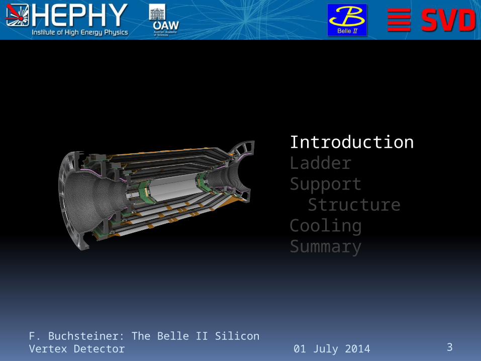
Overview
01 July 2014F. Buchsteiner: The Belle II Silicon Vertex Detector 4
Layer
Radius [mm]
Ladders
Sensors /
Ladder
Slanted?
Windmill angle
[°]
Overlap [%]
6 135 16 5 9 9.0
5 104 12 4 5 3.8
4 80 10 3 6 15.4
3 38 7 2 x 6 7.1
Rect (122.8 x 38.4 mm , 160 / 50 um pitch)2
Rect (122.8 x 57.6 mm , 240 / 75 um pitch)2
W edge (122.8 x 57 .6-3 8.4 m m , 240 / 75..50 um pitch)2
0
0
10
3
45
6[cm] layers
[cm]
20
-10-20-30 10 20 30 40
6
z APVs
z APVs
z APVs
64
4
4 4
46
6
6
rphi APVs
rphi APVs
rphi APVs
6
64
4
4 4
4
4
46
6
66 6
6 6 6
6
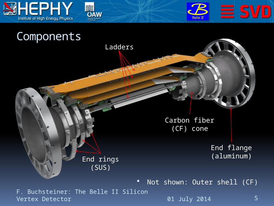
Components
Not shown: Outer shell (CF)
01 July 2014F. Buchsteiner: The Belle II Silicon Vertex Detector 5
Ladders
End rings(SUS)
Carbon fiber(CF) cone
End flange(aluminum)

Requirements & Features
Support for detectors with readout and cooling Light-weight (minimal radiation length) Stable in time (no vibrations except during
earthquake) Absorb thermal gradients
Fully assembled SVD can be split into halves Important for quick assembly/disassembly around
beam pipe and pixel detector (PXD)
PXD + SVD = VXD (Vertex Detector) Also includes beam pipe and heavy metal masks
(enclosed)
01 July 2014F. Buchsteiner: The Belle II Silicon Vertex Detector 6
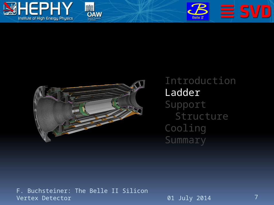
IntroductionLadderSupport
StructureCoolingSummary
01 July 2014F. Buchsteiner: The Belle II Silicon Vertex Detector 7
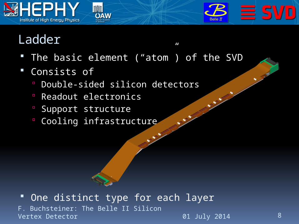
The basic element (“atom”) of the SVD Consists of
Double-sided silicon detectors Readout electronics Support structure Cooling infrastructure
One distinct type for each layer
Ladder
01 July 2014F. Buchsteiner: The Belle II Silicon Vertex Detector 8
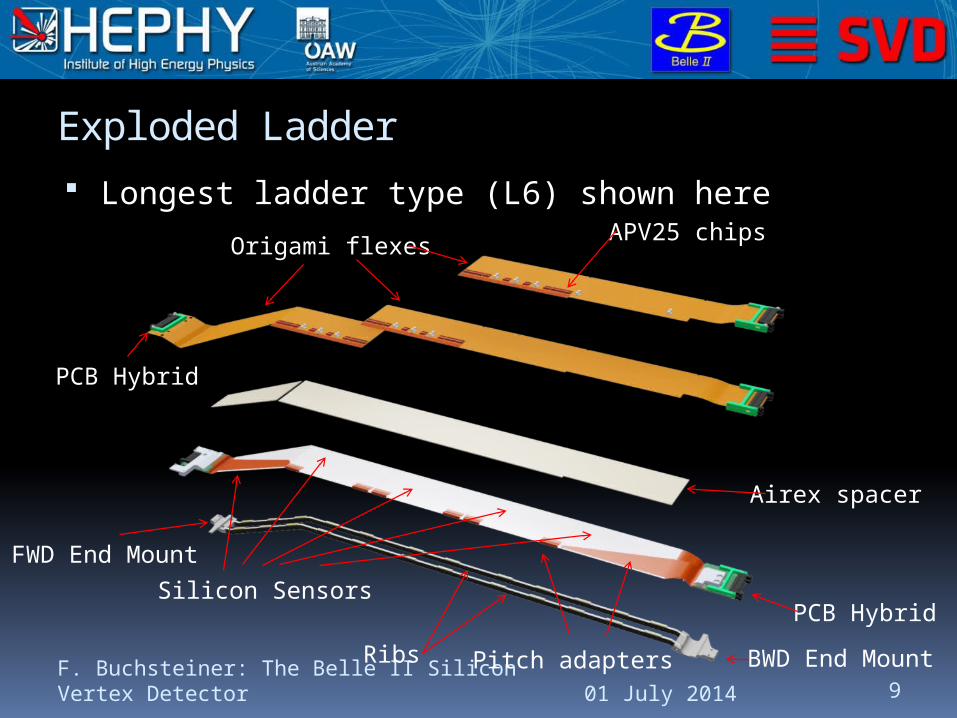
Longest ladder type (L6) shown here
Exploded Ladder
01 July 2014F. Buchsteiner: The Belle II Silicon Vertex Detector 9
Origami flexesAPV25 chips
Airex spacer
Silicon Sensors
PCB Hybrid
PCB Hybrid
Pitch adaptersRibs
FWD End Mount
BWD End Mount
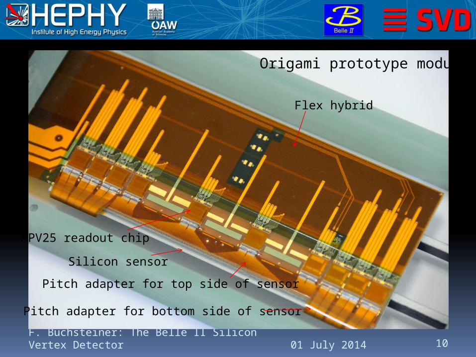
01 July 2014F. Buchsteiner: The Belle II Silicon Vertex Detector 10
Origami prototype module
Silicon sensor
Flex hybrid
Pitch adapter for top side of sensor
Pitch adapter for bottom side of sensor
APV25 readout chip
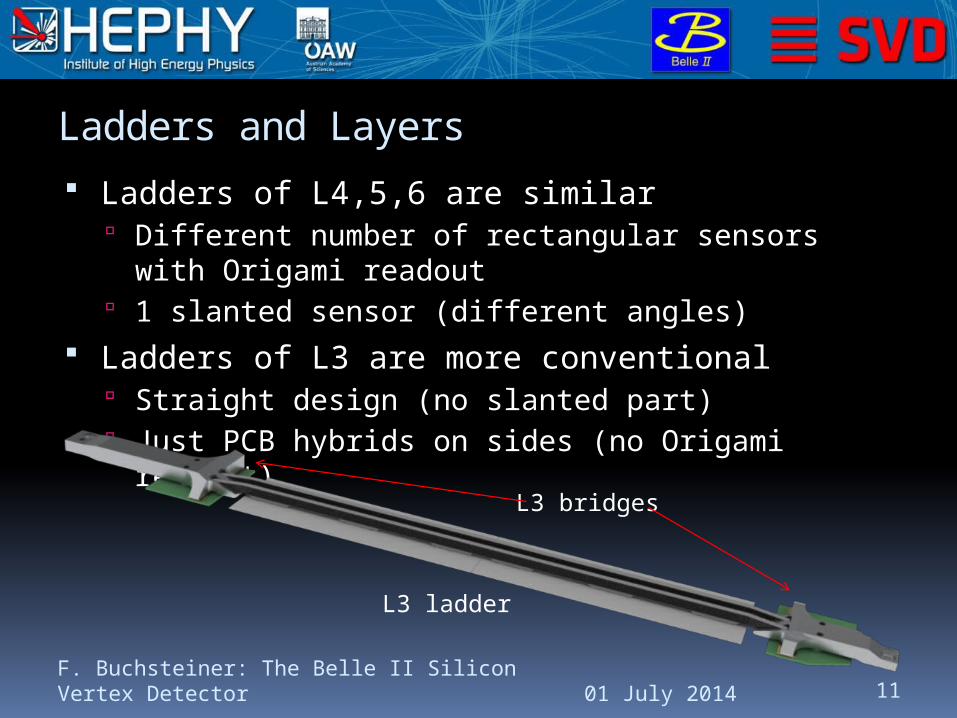
Ladders and Layers
Ladders of L4,5,6 are similar Different number of rectangular sensors with
Origami readout 1 slanted sensor (different angles)
Ladders of L3 are more conventional Straight design (no slanted part) Just PCB hybrids on sides (no Origami readout)
01 July 2014F. Buchsteiner: The Belle II Silicon Vertex Detector 11
L3 ladder
L3 bridges
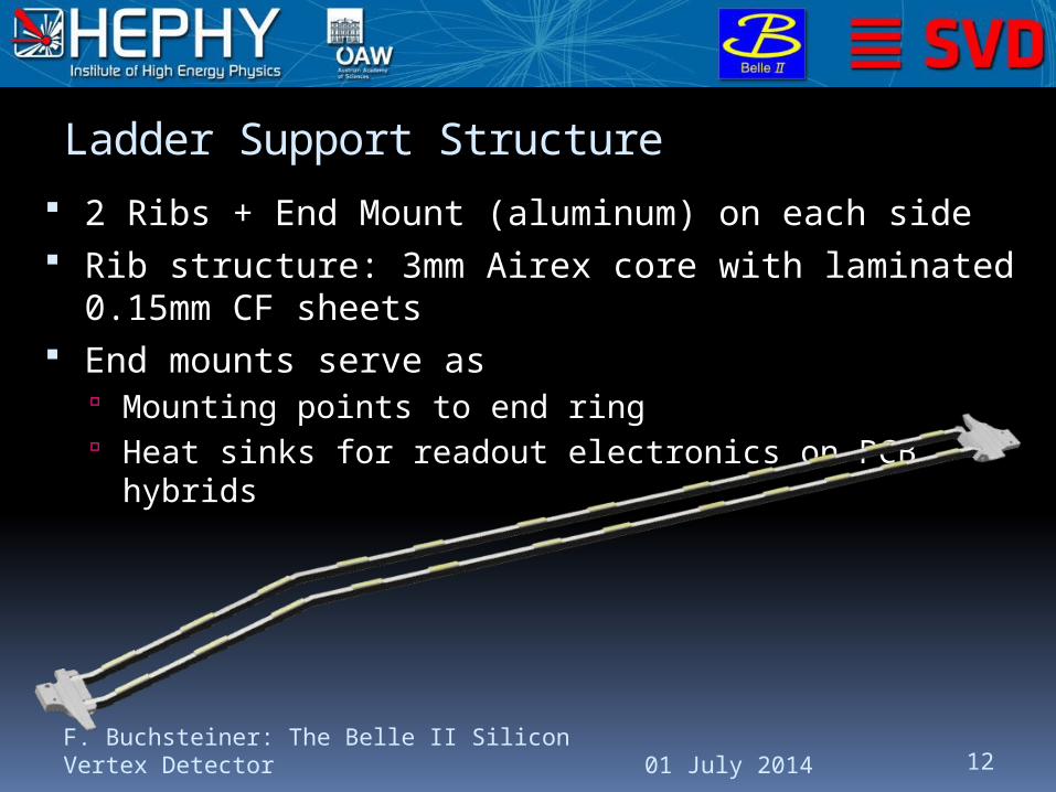
Ladder Support Structure
2 Ribs + End Mount (aluminum) on each side Rib structure: 3mm Airex core with laminated
0.15mm CF sheets End mounts serve as
Mounting points to end ring Heat sinks for readout electronics on PCB hybrids
01 July 2014F. Buchsteiner: The Belle II Silicon Vertex Detector 12
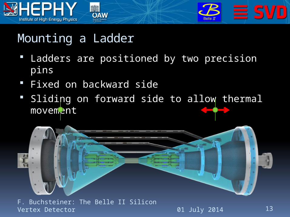
Mounting a Ladder
Ladders are positioned by two precision pins Fixed on backward side Sliding on forward side to allow thermal
movement
01 July 2014F. Buchsteiner: The Belle II Silicon Vertex Detector 13
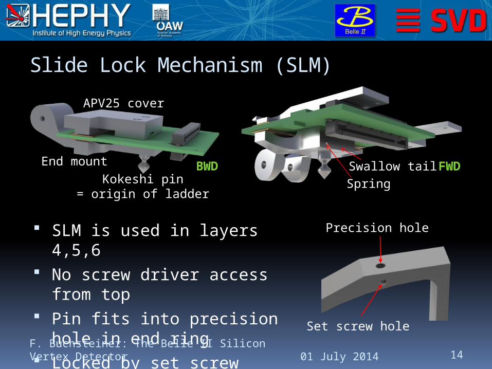
Slide Lock Mechanism (SLM)
SLM is used in layers 4,5,6 No screw driver access from
top Pin fits into precision hole in
end ring Locked by set screw Also provides cooling contact
01 July 2014F. Buchsteiner: The Belle II Silicon Vertex Detector 14
BWD FWD
APV25 cover
End mountKokeshi pin
= origin of ladder
Swallow tailSpring
Precision hole
Set screw hole

Ladder Mount of Layer 3
L3 uses a different approach Very limited space Screwdriver access from top possible
(unlike L4,5,6) Oblong holes for precision pin and
washer + screw (forward side) Precision pin defines position Washer + screw push bridge against end ring
Simple holes for fixed mounting (backward side)
01 July 2014F. Buchsteiner: The Belle II Silicon Vertex Detector 15
Precision pin
Washer + screw
L3 forward side

Issues Addressed
01 July 2014F. Buchsteiner: The Belle II Silicon Vertex Detector 16
Rev. 0.12: Screwed connection between ribs and end mounts Torque to tighten screws caused
deformations of rib Rev. 1.0: new joint without screws Re-design of ribs and end mounts
Rev. 0.12: Individual end mount design in each layer Complex shape Difficult (& expensive) to manufacture Rev. 1.0: unified end mount design for L4-L6 General improvement (simplification) of all parts
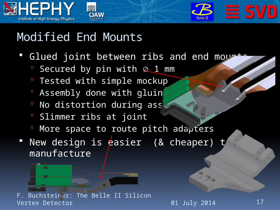
Modified End Mounts
01 July 2014F. Buchsteiner: The Belle II Silicon Vertex Detector 17
Glued joint between ribs and end mounts Secured by pin with 1 mm Tested with simple mockup Assembly done with gluing jig No distortion during assembly Slimmer ribs at joint More space to route pitch adapters
New design is easier (& cheaper) to manufacture

FWD Sliding Mechanism Rev. 0.12
Tricky task: provide thermal contact and allow linear motion
Design with undulated spring was too loose Improved the design
01 July 2014F. Buchsteiner: The Belle II Silicon Vertex Detector 18
Swallow tailSpring
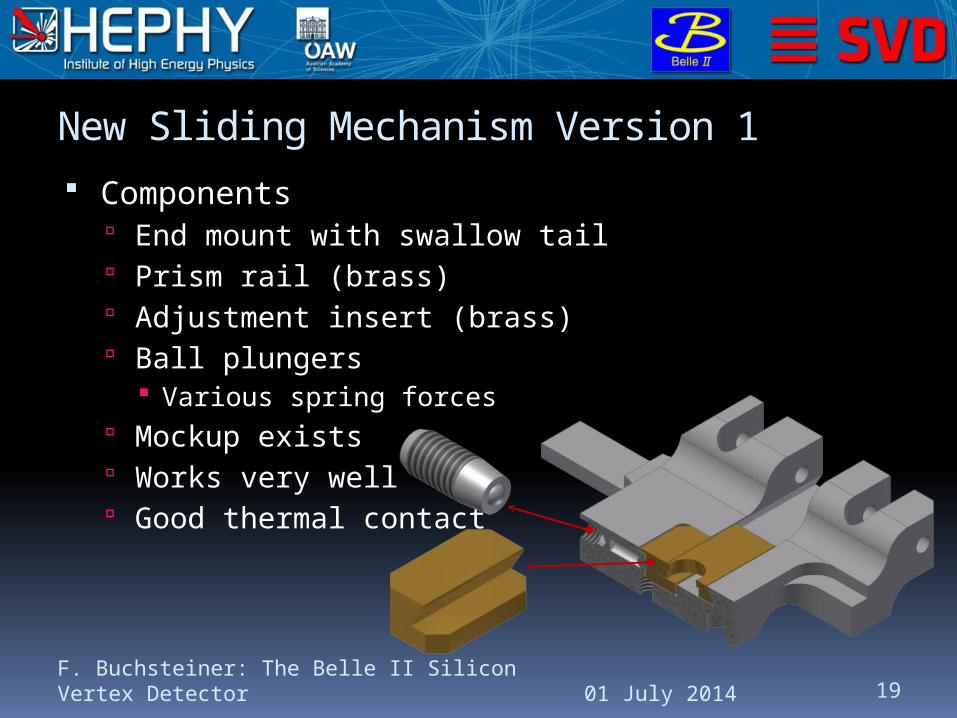
New Sliding Mechanism Version 1
Components End mount with swallow tail Prism rail (brass) Adjustment insert (brass) Ball plungers
Various spring forces Mockup exists Works very well Good thermal contact
01 July 2014F. Buchsteiner: The Belle II Silicon Vertex Detector 19
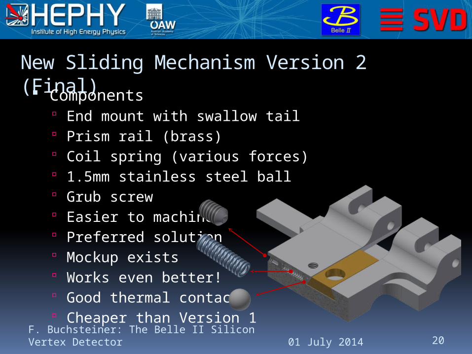
New Sliding Mechanism Version 2 (Final) Components
End mount with swallow tail Prism rail (brass) Coil spring (various forces) 1.5mm stainless steel ball Grub screw Easier to machine Preferred solution Mockup exists Works even better! Good thermal contact Cheaper than Version 1
01 July 2014F. Buchsteiner: The Belle II Silicon Vertex Detector 20

Ribs Rev. 0.12
01 July 2014F. Buchsteiner: The Belle II Silicon Vertex Detector 21
Rib Displacement Volume [cm3]
Dmax [mm]
L6 13.80 7.44
L5 11.18 4.19
L4 8.61 2.29
Dmax under (non-realistic) conditions – only for comparison between variants

Stiffness Improved Ribs (Final)
Significant Dmax improvement in all cases
L5: very limited space towards L4 <1mm clearance to PA1/PA2 in some cases
01 July 2014F. Buchsteiner: The Belle II Silicon Vertex Detector 22
Rib Displacement Volume [cm3]
Dmax [mm]
L6 16.17 1.79
L5 12.37 1.89
L4 8.21 0.63

IntroductionLadderSupport
StructureCoolingSummary
01 July 2014F. Buchsteiner: The Belle II Silicon Vertex Detector 23
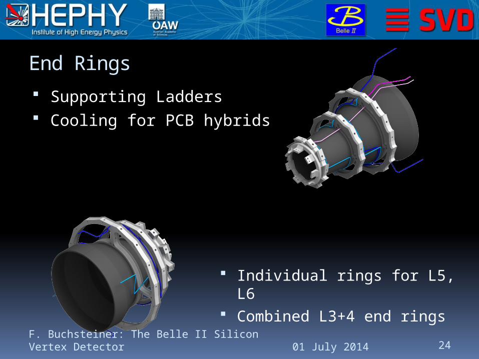
End Rings
Supporting Ladders Cooling for PCB hybrids
01 July 2014F. Buchsteiner: The Belle II Silicon Vertex Detector 24
Individual rings for L5, L6 Combined L3+4 end rings
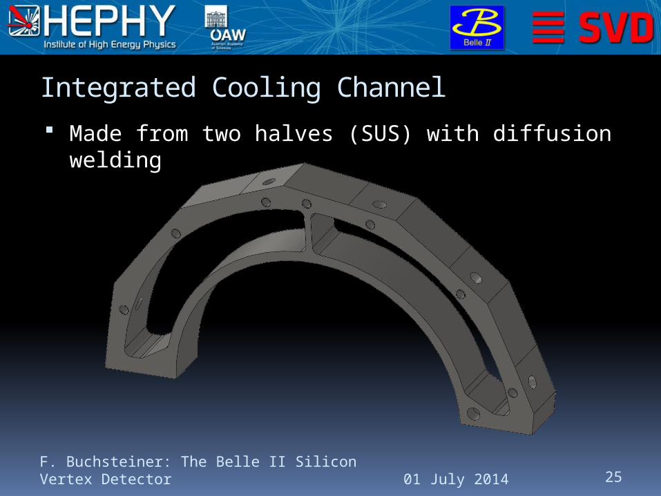
Integrated Cooling Channel
Made from two halves (SUS) with diffusion welding
01 July 2014F. Buchsteiner: The Belle II Silicon Vertex Detector 25
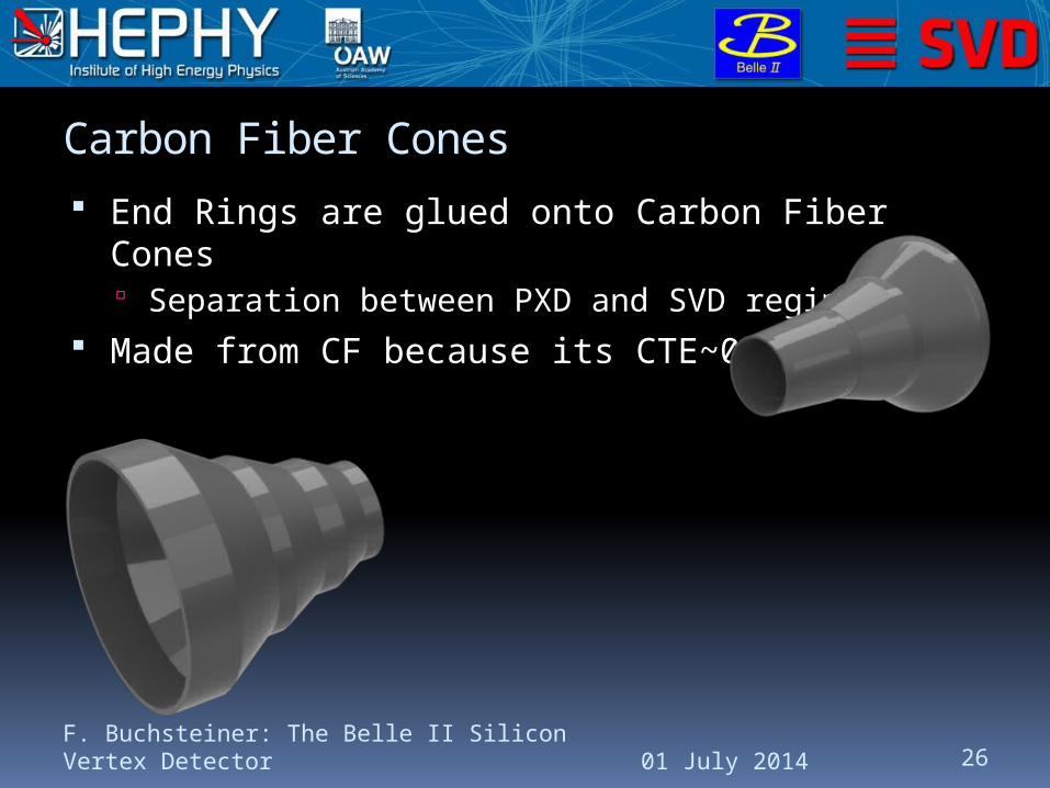
Carbon Fiber Cones
End Rings are glued onto Carbon Fiber Cones Separation between PXD and SVD regimes
Made from CF because its CTE~0
01 July 2014F. Buchsteiner: The Belle II Silicon Vertex Detector 26

End Flanges Supports SVD
End flanges are screwed to CDC Feed-through openings for cables &
pipes
01 July 2014F. Buchsteiner: The Belle II Silicon Vertex Detector 27
Material Aluminum

Outer Shell Only mechanical connection between
forward & backward sides (total VXD ~80kg + part of cable weight)
01 July 2014F. Buchsteiner: The Belle II Silicon Vertex Detector 28
Has to tightly seal the VXD volume (temperature, dew point)

IntroductionLadderSupport
StructureCoolingSummary
01 July 2014F. Buchsteiner: The Belle II Silicon Vertex Detector 29
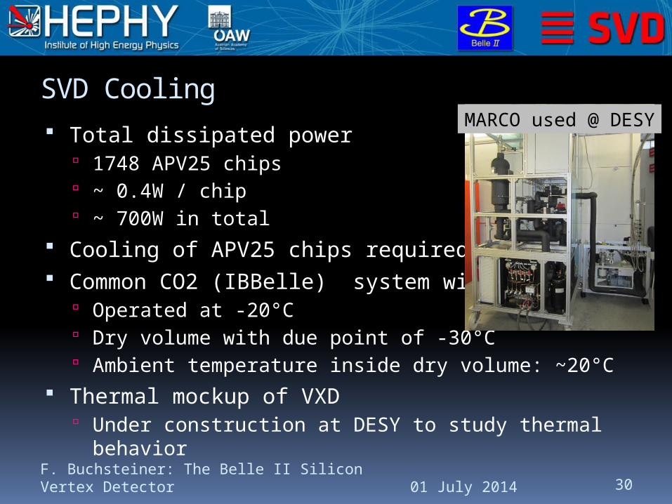
SVD Cooling
Total dissipated power 1748 APV25 chips ~ 0.4W / chip ~ 700W in total
Cooling of APV25 chips required Common CO2 (IBBelle) system with PXD
Operated at -20°C Dry volume with due point of -30°C Ambient temperature inside dry volume: ~20°C
Thermal mockup of VXD Under construction at DESY to study thermal
behavior01 July 2014
F. Buchsteiner: The Belle II Silicon Vertex Detector 30
MARCO used @ DESY
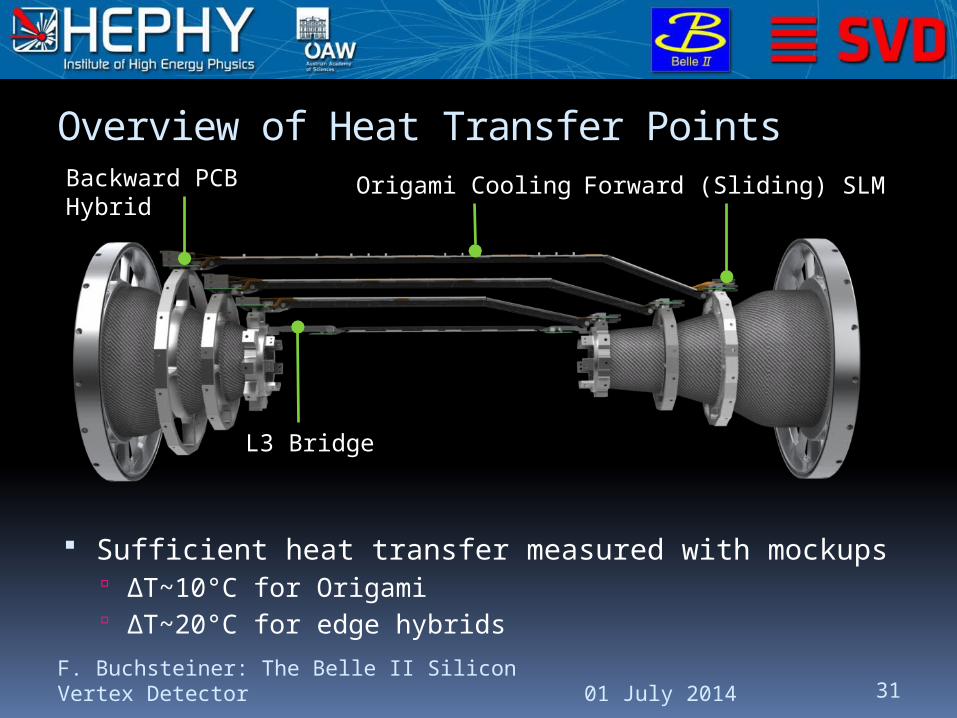
Overview of Heat Transfer Points
01 July 2014F. Buchsteiner: The Belle II Silicon Vertex Detector 31
Origami CoolingBackward PCB Hybrid
Forward (Sliding) SLM
L3 Bridge
Sufficient heat transfer measured with mockups ΔT~10°C for Origami ΔT~20°C for edge hybrids

Cooling of APV25 Chips
Edge hybrids APV25 chips cooled by
end rings End mount / L3 bridges
used as heat sink Origami flexes
100µm thin pre-bent SUS pipe
1.6mm Directly attached to
APV25 chips
01 July 2014F. Buchsteiner: The Belle II Silicon Vertex Detector 32
APV25 chips
End mountEnd ring
APV cover
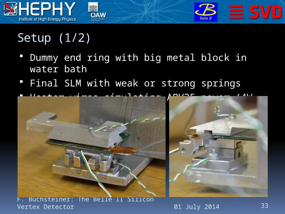
Setup (1/2)
Dummy end ring with big metal block in water bath
Final SLM with weak or strong springs Heater wires simulating APV25 power (4W total)
01 July 2014F. Buchsteiner: The Belle II Silicon Vertex Detector 33
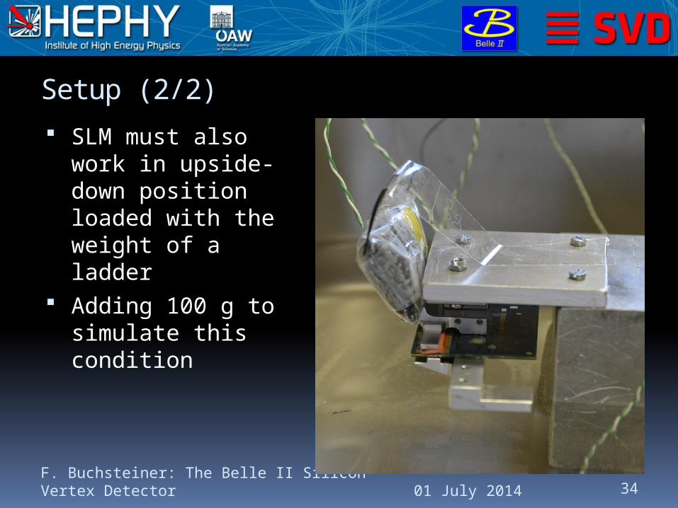
Setup (2/2)
SLM must also work in upside-down position loaded with the weight of a ladder
Adding 100 g to simulate this condition
01 July 2014F. Buchsteiner: The Belle II Silicon Vertex Detector 34

Result With Weak Spring
Larger T with 100 g load spring too weak
01 July 2014F. Buchsteiner: The Belle II Silicon Vertex Detector 35
1000 1500 2000 2500 3000 3500 4000 4500 5000 55000
5
10
15
20
25
30
35
40
45
50Sliding SLM Thermal Mockup Test (weak spring)
3 APV
2 APV guard
1 end ring
0 water bath
Time [s]
Tem
pera
ture
[°C
]
No weight
With 100 g
0 2000 4000 6000 8000 10000 1200010
15
20
25
30
35
40
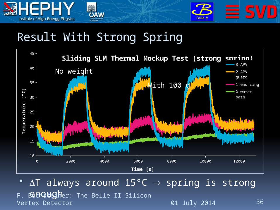
45Sliding SLM Thermal Mockup Test (strong spring)
3 APV
2 APV guard
1 end ring
0 water bath
Time [s]
Tem
pera
ture
[°C
]
Result With Strong Spring
T always around 15°C spring is strong enough
01 July 2014F. Buchsteiner: The Belle II Silicon Vertex Detector 36
No weight
With 100 g
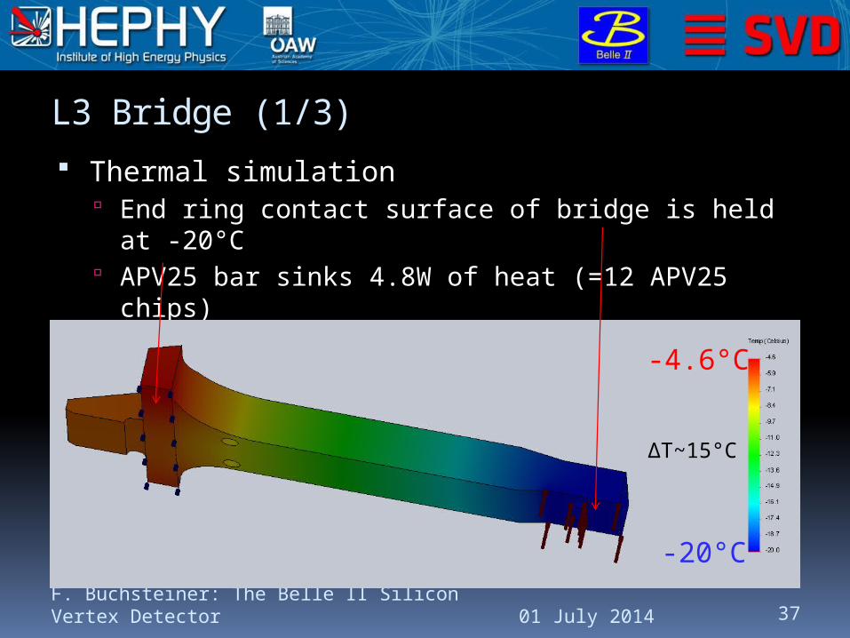
L3 Bridge (1/3)
Thermal simulation End ring contact surface of bridge is held at -20°C APV25 bar sinks 4.8W of heat (=12 APV25 chips)
Result of long bridge (backward side)
01 July 2014F. Buchsteiner: The Belle II Silicon Vertex Detector 37
-4.6°C
-20°C
ΔT~15°C

L3 Bridge (2/3)
Thermocouples:
01 July 2014F. Buchsteiner: The Belle II Silicon Vertex Detector 38
0 water bath
1 heat sink
2 bar back3 bar front
4 APV center
5 APV end
4.8W(dummy APVs)

L3 Bridge (3/3)
01 July 2014F. Buchsteiner: The Belle II Silicon Vertex Detector 39
600 800 1000 1200 1400 160015
20
25
30
35
40L3 Bar Thermal Mockup Test
5 APV end
4 APV cen-ter
3 bar front
2 bar back
1 heat sink
0 water bath
Time [s]
Tem
pera
ture
[°C
]
ΔT~17°CConsistent with simulation
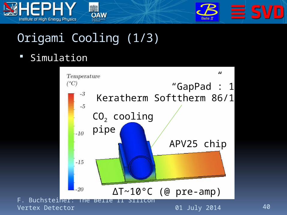
Origami Cooling (1/3)
Simulation
01 July 2014F. Buchsteiner: The Belle II Silicon Vertex Detector 40
CO2 cooling pipe
APV25 chip
“GapPad”: 1mmKeratherm Softtherm 86/125
ΔT~10°C (@ pre-amp)

Origami Cooling (2/3)
Thermal test using 2-sensor-Origami module (20 APV25 chips)
Tested in a dry box with blow CO2 system
Placed a few thermocouples Watched by infrared camera
Unfortunately, no absolute readings
01 July 2014F. Buchsteiner: The Belle II Silicon Vertex Detector 41

Origami Cooling (3/3)
Pipe @ room temperature APV chips much hotter
01 July 2014F. Buchsteiner: The Belle II Silicon Vertex Detector 42
APVs on without cooling APVs on with cooling
Pipe has -16°C (thermocouple)APV chips have similar temp.
Camera does not providecorrect absolute values!
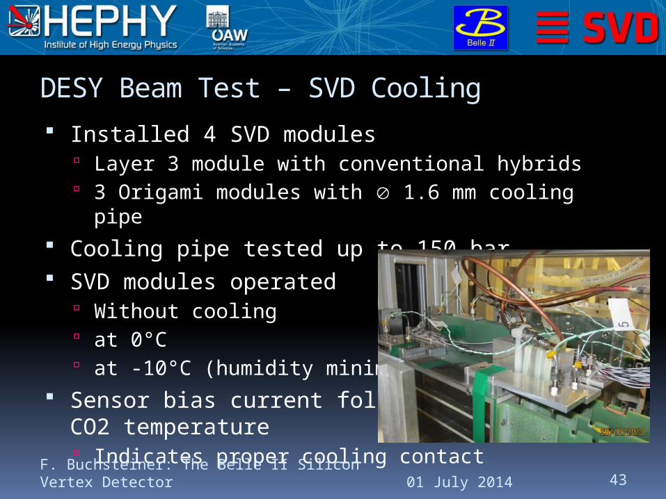
DESY Beam Test – SVD Cooling
Installed 4 SVD modules Layer 3 module with conventional hybrids 3 Origami modules with 1.6 mm cooling pipe
Cooling pipe tested up to 150 bar SVD modules operated
Without cooling at 0°C at -10°C (humidity minimum)
Sensor bias current followed CO2 temperature Indicates proper cooling contact
01 July 2014F. Buchsteiner: The Belle II Silicon Vertex Detector 43

01 July 2014F. Buchsteiner: The Belle II Silicon Vertex Detector 44
IntroductionLadderSupport
StructureCoolingSummary
Summary Mechanics
Revised ladder design Ribs and end mounts FWD sliding mechanism
Fine tuning of end ring design Cooling
Common CO2 cooling with PXD Overall performance will be verified with thermal VXD
mockup DESY test beam: SVD modules cooled down to -10°C
(humidity minimum) Significant decrease of sensor bias current indicates proper
heat transfer Air temperature in box close to that of ambient air
01 July 2014F. Buchsteiner: The Belle II Silicon Vertex Detector 45