Embed Size (px)
Citation preview


The BCA Green Mark Certification Standard for Existing Buildigns (GM Version 3.0) is electronically published by the Building and Construction Authority.
© Building and Construction Authority, January 2016
All rights reserved. No part of this publication may be reproduced or transmitted in any form or my any means, without permission in writing from the publisher.

Addendums and Updates
Addendums and Updates Page DATE
GM Certification Standard Version 3.0 January 2016

BCA Green Mark
Certification Standard
For Existing Buildings
GM Version 3.0
January 2016

Contents
BCA GREEN MARK CERTIFICATION STANDARD FOR EXISTING BUILDINGS
1 Introduction ………………………………………………………………….…….…..…………… 1
2 Scope ……………………………………………….……………………………………..……….. 2
3 Nominative References………………………….……………………………………..……….. 2
4 Terms and Definitions……………………………….……………..……………………………... 2
5 Certification Process …………………………………………..………………………………. 3
6 Assessment Frameworks...….…………………………………..……….….……………………. 4
7 Documentation Requirements…………..………………………………………………………… 22

1
1 INTRODUCTION The intent of this Certification Standard for Existing Buildings (referred to as “Standards”) is to guide owners of existing buildings to improve the minimum sustainability standards of existing buildings and establish environmentally friendly practices in the operation and retrofitting of existing buildings This Standard sets out the requirements for assessing the environmental performance of an existing building. This Standard is not intended to abridge safety, health, environmental or related requirements contained in other applicable laws, codes or policies administered by relevant authorities. Where there is a conflict between a requirement of this Standard and such other laws affecting the design and retrofit of the building, the laws shall take precedence. If you need clarification on any aspect of this Standard, please contact the Building and Construction Authority, Singapore (BCA). The contents of this Standard are protected by copyright and other forms of proprietary rights. All rights, title and interest in the contents are owned by, licensed to or controlled by BCA and shall not be reproduced, republished, uploaded, posted, transmitted or otherwise distributed in any way, without the prior written permission of BCA. Modification of any of the contents or use of the contents for any other purpose will be a violation of BCA's copyright and other intellectual property rights.
2
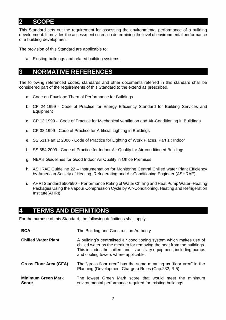
2 SCOPE
This Standard sets out the requirement for assessing the environmental performance of a building development. It provides the assessment criteria in determining the level of environmental performance of a building development The provision of this Standard are applicable to:
a. Existing buildings and related building systems
3 NORMATIVE REFERENCES The following referenced codes, standards and other documents referred in this standard shall be considered part of the requirements of this Standard to the extend as prescribed.
a. Code on Envelope Thermal Performance for Buildings
b. CP 24:1999 - Code of Practice for Energy Efficiency Standard for Building Services and Equipment
c. CP 13:1999 - Code of Practice for Mechanical ventilation and Air-Conditioning in Buildings
d. CP 38:1999 - Code of Practice for Artificial Lighting in Buildings
e. SS 531:Part 1: 2006 - Code of Practice for Lighting of Work Places, Part 1 : Indoor
f. SS 554:2009 - Code of Practice for Indoor Air Quality for Air-conditioned Buildings
g. NEA’s Guidelines for Good Indoor Air Quality in Office Premises
h. ASHRAE Guideline 22 – Instrumentation for Monitoring Central Chilled water Plant Efficiency by American Society of Heating, Refrigerating and Air-Conditioning Engineer (ASHRAE)
i. AHRI Standard 550/590 – Performance Rating of Water Chilling and Heat Pump Water–Heating Packages Using the Vapour Compression Cycle by Air-Conditioning, Heating and Refrigeration Institute(AHRI)
4 TERMS AND DEFINITIONS
For the purpose of this Standard, the following definitions shall apply:
BCA The Building and Construction Authority
Chilled Water Plant
A building’s centralised air conditioning system which makes use of chilled water as the medium for removing the heat from the buildings. This includes the chillers and its ancillary equipment, including pumps and cooling towers where applicable.
Gross Floor Area (GFA) The “gross floor area” has the same meaning as “floor area” in the Planning (Development Charges) Rules (Cap.232, R 5)
Minimum Green Mark Score
The lowest Green Mark score that would meet the minimum environmental performance required for existing buildings.

3
Operational System Efficiency (OSE)
The measured system efficiency of the building’s chilled water plant during its normal operating hours.
Unitary Air Conditioning System
One or more factory-made assemblies that normally include an evaporator or cooling coil and a compressor combination. Units that perform a heating function area are also included.
In instances where terms are not expressly stated in this Code and are defined in other referenced documents, such terms shall have the meanings as determined in those documents.
5 CERTIFICATION PROCESS The BCA Green Mark Certification Process is as follows:
Application
•Submittal of application with relevant supporting documents for certification upon finalisation of sustainable retrofit/practices
•Upon acceptance of application and fee payable, a BCA Green Mark Assessor will be assigned for the duration fo the project
Pre- Assessment
•A pre-assessment audit will be conducted to give the project team a better understanding of the criteria and evaluation of the certification level sought
Actual
Assessment
•Actual assessment to be conducted once the documentary evidence are ready
•Assessment process incldues design and documentary reviews to verify if the buildings project meets () the intents of the criteria and certification level; and (ii) the prerequisites requirements
•For projects with potential BCA Green Mark GoldPlus and pPlatinum rating, there is a requirement for projects to be presented and assessed by panel members
Verification
•For projects with commited items, a site verification will be conducted upon completion of all committed items.
•Site vertification process incldues review of delivery records, updated documents on green features, building energy performance data and photographic evidences. Site inspection and measurement will be conducted.

4
6 ASSESSMENT FRAMEWORK
6.1 General
The environmental performance of an existing building shall be determined by the level of environmental performance and the numerical scores (i.e. Green Mark points) achieved in accordance with the degree of compliance with the applicable criteria using the scoring methodology as specified in this Standard. Under this assessment framework, points are awarded for incorporating sustainable green features and practices, which would add up to ta final Green Mark Score. Depending on the level of building’s performance and Green Mark Score, the existing building will be eligible for certification under one of the four ratings namely BCA Green Mark Certified, Gold, GoldPlus, or Platinum (see table 6.1). The framework and point allocations for the assessment criteria are as illustrated in Table 6.2 and 6.3.
6.2 Environmental Performance of Buildings for Certification
The Green Mark Score of an existing building is the total of all the numerical scores (i.e. Green Mark points) assigned based on the degree of compliance with the applicable criteria. The following table 6.1 states the corresponding Green Mark Score and prerequisite requirements to attain the respective Green Mark rating namely the BCA Green Mark Certified, Gold, GoldPlus, or Platinum.
Table 6.1. BCA Green Mark Award Rating and Prerequisite Requirements
Green Mark Score Green Mark Rating
90 and above Green Mark Platinum
85 to <90 Green Mark GoldPlus
75 to <85 Green Mark Gold
50 to <75 Green Mark Certified
Pre-requisite Requirements for Existing Non-residential Building Criteria
PART 1 - ENERGY EFFICIENCY 1. ENERGY EFFICIENCY
Green Mark Rating Minimum points achievement from
Part 1 – Energy Efficiency
Green Mark Certified 30 points
Green Mark Gold 35 points
Green mark GoldPlus 40 points
Green Mark Platinum 45 points
2. MINIMUM SYSTEMS’ EFFICIENCY
Minimum Design System Efficiency/Operating System Efficiency (DSE/OSE) (i) For buildings using Water-Cooled Chilled-Water Plant
Green Mark Rating
Building Cooling Load (RT)
< 500 ≥ 500
Efficiency (kW/RT)
Certified 0.85 0.75
Gold 0.80 0.70
GoldPlus 0.75 0.68
Platinum 0.70 0.65

5
(ii) For Buildings using Air Cooled Chilled-water Plant or Unitary Air-Conditioner
Green Mark Rating
Building Cooling Load (RT)
< 500 ≥ 500
Efficiency (kW/RT)
Certified 1.1 1.0
Gold 1.0 Not applicable
GoldPlus 0.85
Platinum 0.78
For building with building cooling load of more than 500 RT, the use of air cooled central chilled-water plant or other unitary air-conditioners are not applicable for Gold and higher ratings. Note: The performance of the overall air-conditioning system for the building is based on the Operating System Efficiency (OSE) of the system during the normal building operating hours as defined below:
Office Building: Monday to Friday: 9am to 6pm Retail Mall: Monday to Sunday: 10am to 9pm
Institutional: Monday to Friday: 9am to 5pm
Hotel and Hospital: 24-hour
Industrial and Other Building Types: To be determined based on the operating hours
3. CHILLER PLANT M&V INSTRUMENTATION
(i) Provision of permanent measuring instruments for monitoring of water-cooled chilled-water system and air-cooled chilled water system operating system efficiency. The installed instrumentation shall have the capability to calculate resultant plant operating system efficiency (i.e. kW/RT) within 5% of its true value and in accordance with ASHRAE Guide 22 and AHRI 550/590. Heat balance test for water-cooled chilled-water system is required for verification of the accuracy of the M&V instrumentation.
4. NATURAL VENTILATION AREA (only applicable to occupied areas, excluding circulation, plant rooms
and transit areas ):
Pre requisite requirement for Platinum - At least 75% of natural ventilated areas with effective cross ventilation with North and South facing window opening
PART 4 - INDOOR ENVIRONMENTAL QUALITY 1. IAQ Audit - to conduct an full IAQ audit three yearly that complies with NEA’s Guidelines for Good Indoor Air
Quality in Office Premises or SS554:2009 Code of Practice for `Indoor air quality for air-conditioned buildings' [4 points] [ENRB 4-1(a)]
6.3 Assessment Criteria
The environmental impact categories are broadly classified under two main groupings: (i) Energy Efficiency consists of Part 1- Energy Efficiency where points are allocated for the
various energy efficient systems, practices and features used. A minimum of 30 points must be obtained from this group to meet the minimum environmental sustainability standard.
(ii) Other Green Requirements consist of Part 2 – Water Efficiency; Part 3 – Sustainable
Operation & Management; Part 4 – Indoor Environmental Quality; and, Part 5 – Other Green Features. Points are allocated for the water efficient features, use of environmental friendly practices, waste management and innovative green features used. A minimum of 20 points must be obtained from this group to comply with the minimum environmental sustainability standard.

6
The intent of each category is summaries as below:
(a) Part 1 – Energy Efficiency: This category focuses on greater use of energy efficient building system including air-conditioning, ventilation, lightings, lifts and escalators; and also monitoring of these systems. It also looks at applications of renewable energy and energy efficient features.
Important Note:
Part 1 – Energy Efficiency applies to both air-conditioned and non air-conditioned spaces. Where there is a combination of air-conditioned and non air-conditioned spaces, the points allocated are to be pro-rated in accordance with the respective floor areas. For simplicity, points applicable to air-conditioned areas are accounted only if the aggregate air-conditioned areas exceed 500 m2. Similarly, points applicable to non air-conditioned areas are accounted only if the aggregate non air-conditioned areas are more than 10% of the total floor areas excluding carparks and common areas.
(b) Part 2 – Water Efficiency: This category focuses on the use of water efficient fittings and adoption of water efficient features, which can help to reduce the use of water for building operations.
(c) Part 3 – Sustainable Operation & Management: This category focuses on the building management operation and maintenance, the use of sustainable and environmental-friendly products, provision of waste management and greater use of greenery.
(d) Part 4 – Indoor Environmental Quality: This category focuses on promoting a healthy indoor environment which includes air quality, thermal comfort, minimizing indoor air pollutants, acceptable internal noise level and encourage good lighting quality.
(e) Part 5 – Other Green Features: This category focuses on the adoption of green practices and new technologies that are innovative and have potential environmental benefits.

7
Table 6.2: Framework and Point Allocation for BCA Green Mark for Existing Non-Residential Buildings Criteria (Version 3.0)
CATEGORY POINT ALLOCATION
(I) ENERGY EFFICIENCY
Min
imum
30 p
oin
ts to b
e s
core
d Part 1 – Energy Efficiency
ENRB 1-1 Thermal Performance of Building Envelope 5
ENRB 1-2 Air Conditioning System ENRB 1-3 Natural Ventilation / Mechanical Ventilation
ENRB 1-4 Artificial Lighting 13
ENRB 1-5 Ventilation in Carparks 4
ENRB 1-6 Ventilation in Common Areas 5
ENRB 1-7 Lifts and Escalators 2
ENRB 1-8 Energy Efficient Practices & Features 12
ENRB 1-9 Energy Policy & Management 1
ENRB 1-10 Renewable Energy 15
Category Score for Part 1 – Energy Efficiency 89
(II) OTHER GREEN REQUIREMENTS
Min
imum
20 p
oin
ts to b
e s
core
d
Part 2 - Water Efficiency
ENRB 2-1 Water Monitoring 4
ENRB 2-2 Water Efficient Fittings 12
ENRB 2-3 Alternative Water Sources 3
ENRB 2-4 Water Efficiency Improvement Plans 1
ENRB 2-5 Irrigation System and Landscaping 2
ENRB 2-6 Cooling Towers 2
Category Score for Part 2 – Water Efficiency 24
Part 3 - Sustainable Operation & Management
ENRB 3-1 Building Operation & Maintenance 4
ENRB 3-2 Post Occupancy Evaluation 3
ENRB 3-3 Waste Management 7
ENRB 3-4 Sustainable Products 8
ENRB 3-5 Greenery 10
ENRB 3-6 Environmental Protection 3
ENRB 3-7 Green Transport 4
Category Score for Part 3 – Sustainable Operation and Management
39
Part 4 - Indoor Environmental Quality
ENRB 4-1 Indoor Air Quality Performance 8
ENRB 4-2 Indoor Air Pollutants 2
ENRB 4-3 Lighting Quality 5
ENRB 4-4 Thermal Comfort 2
ENRB 4-5 Internal Noise Level 1
Category Score for Part 4 – Indoor environment Quality 18
Part 5 – Other Green Features
ENRB 5-1 Green Features & Innovations 10
Category Score for Part 5 – Other Green Features 10
Category Score for Other Green Requirements 91
Total Green Mark Score 180
32

8
Table 6.3 : Existing Non-Residential Building Criteria (energy related requirements)
Part 1 - Energy Efficiency Green Mark Points
ENRB 1-1 Thermal Performance of Building Envelope Enhance the overall thermal performance of building envelope to minimize heat gain thus reducing the overall cooling load requirement.
0.5 points for every reduction of 1 W/m2 in ETTV from the baseline of 50 W/m2
Point scored = 0.5 x (50 – ETTV)
(Up to 5 points)
ENRB 1-2 Air-Conditioning System Applicable to Air-conditioned Building Areas (with an aggregate air-conditioned areas > 500m2) Encourage the use of better efficiency air-conditioned equipment to minimize the energy consumption. (System efficiency in kW/ton) (a) Water-Cooled Chilled-Water Plant: a) Water-Cooled Chiller b) Chilled water pump c) Condenser water pump d) Cooling tower
Baseline Building Cooling Load
< 500 RT ≥500 RT
Pre-requisite Requirements Minimum system efficiency of central chilled-water plant
0.85 kW/RT 0.75 kW/RT
OR (b) Air Cooled Chilled-Water Plant / Unitary Air-Conditioners: Air cooled Chilled-Water Plant:
Air-Cooled Chiller Chilled Water Pump
Unitary Air-Conditioners:
Variable Refrigerant Flow (VRF) System Water-Cooled Package Unit Single-Spilt Unit Multi-Spilt Unit
(a) Water-Cooled Chilled-Water Plant
Building cooling load ≥ 500RT
14 points for achieving plant efficiency of 0.75 kW/ton 0.35 point for every percentage improvement in the chiller plant efficiency better than 0.75 kW/ton Point scored = 0.35 x (% improvement)
Building cooling load < 500RT
14 points for achieving plant efficiency of 0.85 kW/ton
0.3 point for every percentage improvement in the chiller plant efficiency better than 0.85 kW/ton Point scored = 0.3 x (% improvement)
(Up to 20 points)
OR
(b) Air-Cooled Chilled-Water Plant/Unitary Air
Conditioners
Building cooling load ≥ 500RT
14 points for achieving plant efficiency of 1.0 kW/ton 0.25 point for every percentage improvement in the chiller plant efficiency better than 1.0 kW/ton Point scored = 0.25 x (% improvement)

9
Part 1 - Energy Efficiency Green Mark Points
Baseline Building Cooling Load
< 500 RT ≥500 RT
Pre-requisite Requirements Minimum system efficiency of air cooled chilled water
plant or unitary conditioners
1.1 kW/RT 1.0 kW/RT
Note: Where there is a combination of centralised air-con system with unitary air-conditioned system, the computation for the points scored will only be based on the air-conditioning system with a larger aggregate capacity.
(c) Air Distribution system:
Air Handling Units (AHUs)
Fan Coil Units (FCUs) Baseline – Fan power limitation in air conditioning system
Allowable nameplate motor power
Constant volume Variable volume
0.47 W/CMH 0.74 W/CMH Note: For buildings using district cooling system, there is no need to compute the plant efficiency under Part 1-2 (a) and (b). The points obtained will be pro-rated based on the air distribution system efficiency under Part 1-2(c)
(d) Prerequisite requirements: Provision of permanent measuring instruments for monitoring of water-cooled chilled-water plant and air-cooled chilled-water plant efficiency. The installed instrumentation shall have the capability to calculate a resultant plant efficiency (i.e. kW/RT) within 5% of its true value and in accordance with ASHRAE Guide 22 and AHRI 550/590. The following instrumentation and installation are also required to be complied with:
Location and installation of the measuring devices to meet the manufacturer’s recommendation.
Data acquisition system to have a minimum resolution of 16 bit.
All data logging with capability to trend at 1 minute sampling time interval.
Dedicated digital power meters shall be provided for the following groups of equipments: chiller(s), chilled water pump(s), condenser water pump(s) and cooling tower(s).
Flow meters to be provided for chilled-water and condenser water loop and shall be of ultrasonic / full bore magnetic type or equivalent.
Temperature sensors are to be provided for chilled water and condenser water loop and shall have an end-to-end measurement uncertainty not exceeding ± 0.05 °C over entire measurement or calibration range. All thermo-wells shall be installed in a manner that ensures that the sensors can be in direct contact with fluid flow. Provisions shall be made for each temperature measurement location to have two spare thermo-wells located at both side of the temperature sensor for verification of measurement accuracy.
Building cooling load < 500RT
14 points for achieving plant efficiency of 1.1 kW/ton 0.2 point for every percentage improvement in the chiller plant efficiency better than 1.1 kW/ton Point scored = 0.2 x (% improvement)
(Up to 20 points)
(c) Air Distribution System 0.15 point for every percentage improvement in the air distribution system efficiency over the baseline
Point scored = 0.15 x (% improvement)
(Up to 8 points)
1 point

10
Part 1 - Energy Efficiency Green Mark Points
(e) Prerequisite requirements: Verification of central
water cooled chilled-water plant instrumentation: Heat Balance – substantiating test for water cooled chilled-water plant to be computed in accordance with AHRI 550/590. The operating system efficiency and heat balance to be submitted to BCA upon commissioning.
(f) Provision of variable speed controls for chiller plant
equipment such as chilled-water pumps and cooling tower fans to ensure better part-load plant efficiency.
(g) Sensors or similar automatic control devices are
used to regulate outdoor air flow rate to maintain the concentration of carbon dioxide.
Carbon dioxide acceptable range ≤ 700 ppm above outdoor
1 point
1 point
1 point
ENRB 1-3 Natural Ventilation / Mechanical Ventilation Applicable to Non Air-Conditioned Building Areas (with an aggregate non air-conditioned areas > 10% of total floor area excluding carparks and common areas)
(a) Natural Ventilation (only applicable to occupied areas,
excluding circulation, plant rooms and transit areas) Encourage building that facilitates good natural ventilation. Proper design of building layout that utilises prevailing wind conditions to achieve adequate cross ventilation.
(b) Mechanical Ventilation Encourage energy efficient mechanical ventilation system as the preferred ventilation mode to air-conditioning in buildings. Baseline: Fan power limitation I mechanical ventilation systems:
Allowable nameplate motor power
Constant volume Variable volume
0.47 W/CMH 0.74 W/CMH
Note : Where there is a combination of naturally ventilated and mechanical ventilated spaces, the points scored will only be based on the predominant ventilation modes of normally occupied spaces.
20 based points will be awarded for use of natural ventilation
1.6 points for every 10% of NV areas with window openings facing north and south
directions and cross ventilation (Up to 32 points)
0.6 point for every subsequent 1% improvement from the baseline
(Up to 32 points)
ENRB 1-4 Artificial Lighting Encourage the use of energy efficient lighting to minimize energy consumption from lighting usage while maintaining proper lighting level. Please refer to the Annex 1 for the baselines of lighting power budget
0.3 point for every percentage improvement in lighting power budget Point scored = 0.3 x (% improvement)
(Up to 13 points) Excluding tenant lighting provision – Up to 5 points)

11
Part 1 - Energy Efficiency Green Mark Points
ENRB 1-5 Ventilation in Carparks Encourage the use of energy efficient design and control of ventilation systems in carparks.
(a) Carparks designed with natural ventilation. (b) CO sensors are used to regulate the demand
for mechanical ventilation (MV)
Note: Where there is a combination of different ventilation mode adopted for carpark design, the points obtained will be prorated accordingly.
Naturally ventilated carparks – 4 points
Points scored based on the mode of mechanical ventilation provided
Fume extract – 2.5 points
MV with or without supply – 2 points
(Up to 4 points)
ENRB 1-6 Ventilation in Common Areas Encourage the use of energy efficient of ventilation systems in the following common areas:
(a) Toilets (b) Staircases (c) Corridors (d) Lift lobbies (e) Atrium
Extent of Coverage: At least 90% of each
applicable area
Point scored based on the mode of ventilation provided in the applicable areas
Natural ventilation – 1.5 points for each area
Mechanical ventilation – 0.5 point for each area
(Up to 5 points)
ENRB 1-7 Lifts and Escalators Encourage the use of energy efficient lifts and escalators. Lifts and/or escalators with AC variable voltage and variable frequency (VVVF) motor drive and sleep mode features.
Extent of Coverage: All lifts and escalators
Lifts – 1 point
Escalators- 1 point
ENRB 1-8 Energy Efficient Practices & Features Encourage the use of energy efficient practices and features which are innovative and/or have positive environmental impact. (a) Computation of the energy consumption in the form
of energy efficiency index (EEI)
(b) Use of energy efficient products that are certified by approved local certification body
(c) Use of energy efficient features
Example:
Re-generative lift
Heat recovery system
Motion sensors
Sun pipes
Light shelves
Photocell sensors to maximize the use of daylight
Heat pumps, etc.
1 point
0.5 point for each equipment type (Up to 2 points)
2 points for every 1% energy saving over the
total building energy consumption (Up to 9 points )

12
Part 1 - Energy Efficiency Green Mark Points
ENRB 1-9 Energy Policy and Management (a) Energy policy, energy targets and regular review
with top management’s commitment as part of an environmental strategy
(b) To show intent, measures and implementation
strategies of energy efficiency improvement plans to achieve energy target set over the next three years. Committed energy savings accrued from proposed measures should be quantified.
0.5 point
0.5 point
ENRB 1-10 Renewable Energy Encourage the application of renewable energy sources in buildings.
Point scored based on the expected energy efficiency index (EEI) and % replacement of
electricity by renewable energy source
Energy Efficiency Index (EEI)
Every 1% replacement of electricity (based on total electricity consumption)
by renewable energy source Include tenant’s usage
Exclude tenant’s usage
≥ 50 kWh/m²/yr
5 points 3 points
< 50 kWh/m²/yr
3 points 1.5 points
(Up to 15 points)
PART 1 – ENERGY EFFICIENCY
CATEGORY SCORE:
(Part 1-2) X Air-conditioned Building Floor Area
Total Floor Area +
(Part 1-3) X Non Air-Conditioned Building Floor Area Total Floor Area
+ (Part 1-1, Part 1-4 to Part 1-10)
Where Part 1-2 = Total Green Mark Points obtained under Part 1-2 Part 1-3 = Total Green Mark Points obtained under Part 1-3 Part 1-1, Part 1-4 to Part 1-10 = Total Green Mark Points obtained under Part 1-1, Part 1-4 to Part 1-10

13
Part 2 - Water Efficiency Green Mark Points
ENRB 2-1 Water Monitoring Provide private-metering and leak detection system for better control and monitoring. (a) To monitor the water consumption on monthly
basis (b) Provision of private-meters for major water uses
(e.g. cooling tower, water features, irrigation, swimming pools, tenants’ usage)
(c) Provision of automated / smart metering for
monitoring and leak detection.
1 point
1 point
2 point
ENRB 2-2 Water Efficient Fittings Encourage the use of water efficient fittings under Water Efficiency Labelling Scheme (WELS) or adopt equivalent water efficient flow-rate/flush volumes for water fittings:-
Basin taps and mixers Showers Sink/Bib taps and mixers Urinals and Urinal Flush Valves Dual-Flush Low Capacity Flushing Cisterns
Or To have PUB Water-Efficient Building Certificate.
Rating based on Water
Efficiency Labeling Scheme
(WELS)
Points scored based on the
number and water efficiency rating of
the fitting type used
(up to 12 points)
Very Good Excellent
Weightage
9 12
9 points
ENRB 2-3 Alternative Water Sources Use of suitable systems that utilize alternative water sources for non-potable uses: irrigation, washing, water features, toilet flushing, etc (excluding cooling tower make up water) to reduce use of potable water. Alternative sources can include rainwater, greywater (for toilet flushing only), NEWater, AHU condensate and recycled water from approved sources.
Points awarded based on % reduction in total potable water usage of the applicable uses
> 50 % - 3 points ≥ 10 % to 50 % - 2 points < 10 % - 1 point
(Up to 3 points)
ENRB 2-4 Water Efficiency Improvement Plans Targets to improve building water performance against own building water performance baseline should be set. To show intent, measures and implementation strategies of water efficiency improvement plans over the next three years. Committed water savings accrued from proposed measures should be quantified. (PUB water efficiency management plan is acceptable as evidence)
1 point

14
Part 2 - Water Efficiency Green Mark Points
ENRB 2-5 Irrigation System and Landscaping (a) Use of automatic water efficient irrigation system
with rain sensor, soil moisture sensor or equivalent control system.
(b) Use of drought tolerant plants that require minimal irrigation.
Extent of Coverage: At least 50% of the landscape areas are served by the system
1 point
Extent of Coverage: At least 50% of the landscape areas
1 point
ENRB 2-6 Cooling Towers Reduce potable water use for cooling purpose. (a) Use of cooling tower water treatment system which
can achieve 7 or better cycles of concentration at acceptable water quality.
(b) Use of NEWater or on-site recycled water from approved sources.
1 point
1 point
PART 2 – WATER EFFICIENCY
CATEGORY SCORE :
Sum of Green Mark Points obtained from
ENRB 2-1 to 2-6

15
Part 3 - Sustainable Operation & Management Green Mark Points
ENRB 3-1 Building Operation & Maintenance
(a) The environmental policy that reflects the sustainability goals set.
(b) A green guide for the occupants or visitors should
be disseminated through various channels. Best practices to reduce energy use, water use and maintain a good indoor environment should be documented in this green guide. To demonstrate evidences of occupant involvement in environmental sustainability.
(c) In-house building management team comprises one Certified Green Mark Facilities Manager (GMFM), Singapore Certified Energy Manager (SCEM) / Green Mark Professional (GMP).
(d) The environmental management system of the building is ISO14000 or ISO 50001 certified.
1 point
1 point
0.5 point for certified GMFM 1 point for certified SCEM / GMP
(Up to 1 point)
1 point
ENRB 3-2 Post Occupancy Evaluation (a) Conduct post occupancy survey for occupant’s
satisfaction on energy and environmental performance. Required number of people surveyed shall be:
- 10% of total occupancy and up to 100 maximum.
- minimum 5 people shall be surveyed if total occupancy is less than 50.
(b) List of corrective actions taken following the post
occupancy evaluation, if any.
2 points
1 point
ENRB 3-3 Waste Management a) Provision of facilities or recycling bins for collection
and storage of different recyclable waste such as paper, glass, plastic, food waste, etc.
b) Promote and encourage waste minimization and recycling among occupants, tenants and visitors through various avenues.
c) Provide the proper storage area for the recyclable waste.
d) To quantify and monitor the recycling programme
for continuous improvement.
2 points
2 points
1 point
2 points

16
Part 3 - Sustainable Operation & Management Green Mark Points
ENRB 3-4 Sustainable Products Promote use of environmentally friendly products that are certified by approved local certification body.
Weightage based on the extent of environmental friendliness of products
Points scored based on the weightage and
the extent of coverage & impact
1 point for high
impact item
0.5 point for low impact item
(Up to 8 points)
Good
Very Good
Excellent
1
1.5
2
ENRB 3-5 Greenery Encourage greater use of greenery to reduce heat island effect. (a) Greenery Provision (GnP) is calculated by
considering the 3D volume covered by plants using the following Green Area Index (GAI) :
Grass GAI = 1 ; Shrubs GAI = 3; Palms Trees GAI = 4; Trees GAI = 6
(b) Use of compost recycled from horticulture waste. (c) Provision of roof top greenery (d) Provision of Vertical Greenery
GnP = 0.5 to < 1.0 - 1 point GnP = 1.0 to < 2.0 - 2 points GnP = 2.0 to < 3.0 - 3.5 points GnP ≥ 3.0 - 5 points
(Up to 5 points)
1 point
For roof top greenery areas
≥ 20% & 50% of useable roof areas - 1 point
≥ 50% of useable roof areas - 2 points
For Vertical greenery areas
≥10m2 and <50m2 - 1 point
≥ 50m2 - 2 points
ENRB 3-6 Environmental Protection
(a) Green procurement policy – Adoption of sustainable and environmental-friendly procurement and purchasing policy in the operation and maintenance of the building.
(b) Reduce the potential damage to the ozone layer and the increase in global warming through the release of ozone depleting substances and greenhouse gases.
Refrigerants with ozone depletion potential (ODP) of zero or with global warming potential (GWP) of less than 100.
Use of refrigerant leak detection system at
critical areas of plant rooms containing chillers and other equipments with refrigerants.
1 point
1 point
1 point

17
Part 3 - Sustainable Operation & Management Green Mark Points
ENRB 3-7 Green Transport Promote the use of public transport or bicycles to reduce pollution from individual car use with the following provision: (a) Good access to nearest MRT/LRT or bus stops.
(b) Provision of covered walkway to facilitate
connectivity and the use of public transport
(c) Provision of priority parking lots for hybrid/electric vehicle within the development
(d) Provision of sheltered bicycle parking lots with
adequate shower and changing facilities.
1 point
1 point
1 point
Extent of Coverage : Minimum 10 number of bicycle parking lots, cap at 30 where
applicable
Points scored based on the number of bicycle parking lots provided (with adequate shower
and changing facilities)
1 point if the number provided ≥ 1% x GFA/10
0.5 point if the number provided
≥ 0.5% x GFA/10
PART 3 – SUSTAINABLE OPERATION AND MANAGEMENT
CATEGORY SCORE :
Sum of Green Mark Points obtained from ENRB 3-1 to 3-7

18
Part 4 – Indoor Environmental Quality Green Mark Points
ENRB 4-1 Indoor Air Quality Performance
To promote a healthy indoor environment. (a) Prerequisite Requirements: To conduct full IAQ
audit once in three years that complies with NEA’s Guidelines for Good Indoor Air Quality in Office Premises or SS554:2009 Code of Practice for `Indoor air quality for air-conditioned buildings' by an accredited laboratory under the Singapore Accreditation Council.
(b) Implement effective IAQ management plan to ensure building ventilation systems are frequently maintained to ensure or clean delivery of air.
(c) Use of high efficiency air filter (at least MERV 13) in AHU to reduce indoor contaminants and provide good protection for cooling coil and reducing frequency or eliminating duct cleaning
(d) Room temperature display (at least 1 unit per
floor)
(e) Additional carbon dioxide sensor display (at least 1 unit per floor)
4 points
1 point
1 point
1 point
1 point
ENRB 4-2 Indoor Air Pollutants
Minimise airborne contaminants, mainly from inside sources to promote a healthy indoor environment.
(a) Use of low volatile organic compounds (VOC) paints certified by an approved local certification body.
(b) Use of environmental friendly adhesives certified by an approved local certification body.
1 point
1 point
ENRB 4-3 Lighting Quality To encourage good workplace lighting quality to promote productivity and occupant comfort (a) Lighting level to comply with SS531:Part 1:2006 or
CP38:1999 for various uses.
(b) Controllability of lighting system
1 point
At least 90% of occupants are able to adjust lighting to suit their task needs and preference
Controlled by light switches - 1 point Controlled by task lights - 2 points
(Up to 2 points)

19
Part 4 – Indoor Environmental Quality Green Mark Points
(c) High frequency ballast
All applicable areas in the entire building that
are served by fluorescent lightings
20% to < 40% - 0.5 point 40% to < 60% - 1 point 60% to < 80% - 1.5 points 80% and above - 2 points
(Up to 2 points)
ENRB 4-4 Thermal Comfort (a) Ensure the consistent indoor conditions for
thermal comfort:
Indoor dry-bulb temperature within 22.5 °C to 25.5 °C and relative humidity <70%
(b) Controllability of temperature
1 point
1 point
ENRB 4-5 Internal Noise Level Ensure internal noise level are maintained at an appropriate levels and to comply with CP13:1999 or SS553:2009
1 point
PART 4 – INDOOR ENVIRONMENTAL QUALITY
CATEGORY SCORE :
Sum of Green Mark Points obtained from ENRB 4-1 to 4-5

20
Part 5 – Other Green Features Green Mark Points
ENRB 5-1 Green Features and Innovations To encourage the use of other green features which are innovative and/or have positive environmental impact. Examples :
Tenants with Green Mark for Office Interior or Restaurant
Green Lease
Ultraviolet light-C band (UV) emitters in air handling units (AHUs) to improve indoor air quality
Provision of carpark guidance system
Use of self cleaning façade system
Use of grey water recycling system
Titanium Dioxide coating to remove odour in toilets
Use of pneumatic waste collection system
Use of double refuse chutes for separating recyclable from non-recyclable wastes
Stormwater management
Power meter to monitor air side systems
Green Mark Pearl and Prestige Awards
Chiller plant performance contract with SGBC accredited EPC firms.
2 points for high impact item
1 point for medium impact item
0.5 point for low impact item
(Up to 10 Points)
PART 5 – OTHER GREEN FEATURES
CATEGORY SCORE :
Sum of Green Mark Points obtained from ENRB 5-1
Green Mark Score (Existing Non-Residential) Green Mark Score = Σ Category Score [(Part 1 – Energy Efficiency) + (Part 2 – Water Efficiency) + (Part 3 – Sustainable Operation and Management) + (Part 4 – Indoor Environmental Quality) + (Part 5 – Other Green Features)] Where Category Score for Part 1 ≥ 30 points and Σ Category score for Part 2, 3, 4 & 5 ≥ 20 points

21
Annex 1: Maximum lighting power budget (including ballast loss)
Type of usage Maximum lighting power
budget (W/m2)
Offices 15
Classrooms 15
Hotel guest room 15
Lecture theatres 15
Auditoriums / Concert halls 10
Shops / Supermarkets / Departmental stores (including general, accent &
display lighting) 25
Restaurants 15
Lobbies / Atriums / Concourse 10
Stairs 10
Corridors 10
Car parks 5
Electronic manufacturing and fine detail / Assembly industries 20
Medium and heavy industries 15
Warehouses / Storage areas 10

22
7 DOCUMENTATION REQUIREMENTS
The details of the documentary evidences required can be found in the Appendix A: Scoring Methodology & Documentation for compliance. Building Owner, PE(Mech) and appropriate practitioners shall ensure that these documents and records are available as evidences to demonstrate compliance with the environmental sustainability standard and criteria.

23
Appendix A
SCORING METHODOLOGY & DOCUMENTATION
24
(I) Energy Related Requirements
Part 1 – Energy Efficiency
ENRB 1-1 Thermal Performance of Building Envelope
ENRB 1-2 Air Conditioning System
ENRB 1-3 Natural Ventilation / Mechanical Ventilation
ENRB 1-4 Artificial Lighting
ENRB 1-5 Ventilation in Car parks
ENRB 1-6 Ventilation in Common Areas
ENRB 1-7 Lifts and Escalators
ENRB 1-8 Energy Efficient Practices & Feature
ENRB 1-9 Energy Policy & Management
ENRB 1-10 Renewable Energy

25
ENRB 1-1 THERMAL PERFORMANCE OF BUILDING ENVELOPE
Objectives
Enhance overall thermal performance of building envelope to minimize heat gain thus reducing the overall cooling load requirement.
Applicability
Applicable to air-conditioned building spaces with aggregate areas > 500 m2.
Baseline Standard
ETTV stands for Envelope Thermal Transfer Value. Maximum permissible ETTV = 50 W/m2
The computation of ETTV shall be based on the methodology specified in the Code on Envelope Thermal Performance for Buildings issued by BCA.
Requirements
Up to 5 points can be scored for building envelope with better thermal performance than the baseline standard : 0.5 points for every reduction of 1 W/m2 in ETTV from the baseline of 50W/m2
Points scored = 0.5 x (50 – ETTV) where ETTV ≤ 50 W/m2 For developments consisting of more than one building, the weighted average of the ETTVs based on the façade areas of these buildings shall be used as the basis for point allocation.
ETTV Weighted Average = ∑ (ETTVbldg xAbldg) / Adevt
where ETTVbldg = ETTV for a building (W/m2) Abldg = Summation of all facade areas that enclose all the air-conditioning
areas (m2) in a building Adevt = Summation of total applicable facade areas of all buildings within the
development (m2) (i.e. ∑ Abldg)
Note: For buildings that are underground, full 5 points will be given.
Documentary Evidences
Architectural elevation drawings showing the composition of the different façade
or wall systems that are relevant for the computation of ETTV; Architectural plan layouts and elevations showing all the air-conditioning areas; Technical specifications of material showing the salient data of the material
properties that were used for the façade or external wall system; and ETTV calculation.
References
Code on Envelope Thermal Performance for Buildings (2008) issued by BCA.

26
Worked Example for 1-1
Example 1 ETTV = 45 W/m2
Points scored = 0.5 x (50 – ETTV)= 0.5 x (50 - 45) = 2.5 points Example 2 ETTV = 35 W/m2
Points scored = 0.5 x (50 – ETTV) = 0.5 x (50 – 35) = 7.5 points > 5 points Therefore, points scored should be 5 points (max)
Example 3 A proposed building development comprises three building blocks. The individual ETTV of the each building computed are as follows : ETTV bldg1 = 35 W/m2 Abldg = 5000 m2 ETTVbldg2 = 45 W/m2 Abldg = 6800 m2 ETTVbldg3 = 50 W/m2 Abldg = 7500 m2 Therefore
ETTV Weighted Average = ∑ (ETTVbldg xAbldg) / Adevt
= (ETTVbldg1 xAbldg1) + (ETTVbldg2 xAbldg2) + (ETTVbldg3 xAbldg3) (Adevt) = (35 x 5000) + (45 x 6800) + (50 x 7500) 19300 = 44.35 W/m2 Points scored = 0.5 x (50 – ETTV) = 0.5 x (50 – 44.35) = 2.83 points Note : Refer to the Code on Envelope Thermal Performance for Buildings for more detailed examples on how to compute the ETTV.
Adevt = 5000+6800+7500 = 19300 m2

27
ENRB 1-2 AIR-CONDITIONING SYSTEM
Objectives
Encourage the use of better energy efficient air-conditioned equipments to minimize energy consumption.
Applicability
Applicable to air-conditioned building areas where its aggregate air-conditioned areas > 500 m2. Scope covers all air-conditioned equipments for the buildings as listed:
Chillers
Chilled-Water Pumps
Condenser Water Pumps
Cooling Towers
Air Handling Units (AHUs)
Fan Coil Units (FCU)
Direct-Expansion (DX) Unitary Air-Conditioners / Condensing Units which include single-split units, multi-spilt units and variable refrigerant flow (VRF) system
Baseline Standard
1-2(a) Water Cooled Chilled-Water Plant
Baseline Building Cooling Load
< 500 RT ≥ 500 RT
Pre-requisite Requirements Minimum System Efficiency for Water-cooled Chilled Water Plant
0.85 kW/RT 0.75 kW/RT
1-2(b) Air Cooled Chilled-Water Plant/ Unitary Air-Conditioners
Baseline Building Cooling Load
< 500 RT ≥ 500 RT
Pre-requisite Requirements Minimum System Efficiency for Air Cooled Chilled-Water Plant or Unitary Air-Conditioners
1.1 kW/RT 1.0 kW/RT
1-2(c) Air Distribution System
For air distribution fan systems, the fan motor power required shall not exceed the baseline as shown in the table below.
Constant Air Volume System Variable Air Volume System
0.47 W/cmh 0.74 W/cmh

28
Requirements for 1-2(a) & 1-2(b)
1-2 (a) Water Cooled Chilled-Water Plant (Up to 20 points)
14 points for achieving chiller plant efficiency of 0.75 kW/RT.
0.35 point for every percentage improvement in the chiller plant efficiency better than 0.75 kW/RT.
Points scored = 0.35 x (% improvement)
14 points for achieving chiller plant efficiency of 0.85 kW/RT.
0.3 point for every percentage improvement in the chiller plant efficiency better than 0.85 kW/RT.
Points scored = 0.3 x (% improvement)
1-2 (b) Air Cooled Chilled-Water Plant
14 points for achieving chiller plant efficiency of 1.0 kW/RT.
0.25 points for every percentage improvement in the air-conditioning system efficiency better than 1.0 kW/RT.
Points awarded = 0.25 x (% improvement)
14 points for achieving chiller plant efficiency of 1.1 kW/RT.
0.2 point for every percentage improvement in the air-conditioning system efficiency better than 1.1 kW/RT.
Points awarded = 0.2 x (% improvement)
Important notes :
Building cooling load ≥ 500 RT
Building cooling load < 500 RT
Building cooling load ≥ 500 RT
Building cooling load < 500 RT

29
Requirements for 1-2(c) Requirements for 1-2(d)
(i) Where there is a combination of central chilled-water plant with unitary air-conditioned system, the computation for the points scored will only be based on the air-conditioning system with a larger aggregate capacity.
(ii) The building cooling load and chiller plant system efficiency can be determined based on the measured operating conditions of the system; which shall include the chillers, pumps, cooling towers and associated equipment.
(iii) For simplicity and consistency, the expected operating efficiency will be based on the total energy consumption over total hourly cooling loads during the specified building operation hours as defined below :
Office Buildings:
Monday to Friday : 9 am to 6 pm Retail Malls :
Monday to Sunday : 10 am to 9 pm Hotels and serviced apartments :
Monday to Sunday : 24 Hours (day time load: 7am to 11pm; night time load: 11pm to 7am)
Other Building Types To be determined based on operating hours
(iv) For the design system efficiency, the expected chilled water plant efficiency shall be calculated based on the measured building cooling load profile through an Energy Audit before the retrofit. The energy audit shall be performed by an accredited Energy Services Company (ESCO) or a Professional Mechanical Engineer (Mech).
(v) For air-cooled variable refrigerant flow system and unitary air-conditioners, the efficiency shall be computed based on the efficiency of rated capacity or at the expected operating part-load condition of the outdoor condensing units.
1-2 (c) Air Distribution System (Up to 8 points)
0.15 point for every percentage improvement in the air distribution system efficiency above the baseline.
Constant Air Volume System Variable Air Volume System
0.47 W/cmh 0.74 W/cmh
Points scored = 0.15 x (% improvement)
The efficiency of the air distribution system can be determined from the rated fan power and air flowrate of the AHU and FCU or by site measurement.
1-2 (d) Instrumentation for Monitoring Central Chilled Water Plant Efficiency
1 point for the provision of permanent measuring instruments for monitoring of water-cooled and air-cooled chilled-water plant efficiency. The installed instrumentation shall have the capability to calculate resultant chilled-water plant efficiency (i.e. kW/RT) within ± 5 % of the true value and in accordance with
ASHRAE Guide 22 and AHRI 550/590.

30
Requirements for 1-2(e)
The following instrumentation and installation are also required to be complied with :
(a) Location and installation of the measuring devices to meet the manufacturer’s recommendation.
(b) Data Acquisition system i.e. Analog-to-digital or A/D converter used shall have a minimum resolution of 16 bit. For example,
The specification for the A/D converter of the BTU meter should have a minimum resolution of 16-bit. This applies to direct data acquisition from the BTU meter.
For data acquisition using Building Management System (BMS), the specification of the specific Digital Direct Controller (DDC) connecting the temperature sensors should have a minimum resolution of 16-bit.
(c) All data logging with capability to trend at 1 minute sampling time interval.
(d) Flow meters for chilled-water and condenser water loop shall be ultrasonic / full bore magnetic type or equivalent.
(e) Temperature sensors are to be provided for chilled water and condenser water loop and the measurement system shall have an end-to-end uncertainty from the temperature sensors to the read out devices not exceeding ± 0.05 °C over the entire measurement or calibration range. All thermo-wells shall be installed in a manner that ensures that the sensors can be in direct contact with fluid flow.
(f) Provisions shall be made for each temperature measurement location to have two spare thermo-wells located at both side of the temperature sensor for verification of measurement accuracy.
(g) Dedicated digital power meters shall be provided for the following groups of equipment: chiller(s), chilled water pump(s), condenser water pump(s) and cooling tower fan(s).
1-2 (e) Heat balance Substantiating test
1 point for submitting the verification of chilled-water plant instrument using the heat balance-substantiating test in accordance with AHRI 550/590. The heat balance shall be computed over the entire normal operating hours with more than 80% of the computed heat balance within ± 5% over a one (1) week period.
For a perfectly balanced chiller system, the heat balance is represented by the following equation:
qcondenser = qevaporator + Winput
where qcondenser = heat rejected
qevaporator = cooling load
Winput = power input to compressor
The pressure enthalpy diagram below shows the concept of heat balance equation in a vapour compression cycle.

31
Pressure Enthalpy Chart
The system heat balance of the chilled water plant shall be computed using the formula stated below over the normal operating hours,
Percent Heat Balance =
Note: For open drive chillers, the Winput shall take into account the motor efficiency provided by the manufacturer. An example is provided as follows:
Input power to motor = 100kW (measured)
Motor rated efficiency (η) = 90%
Adjusted power input to compressor Winput = 100kW x 90%
= 90kW In the event where hydraulic losses of pumps constitute a substantial heat gain, these losses could be accounted for. The values shall be determined from motor efficiency and pump efficiency values provided by the manufacturer. Examples are illustrated as follows:
(a) For chilled water pump(s) adjustment,
Motor input power (measured) = 30 kW (A)
Motor rated efficiency (η) = 90% (B)
Pump rated efficiency (η) = 80% (C)
Hydraulic losses = (A) x (B) x [(100% – (C)]
= 30kW x 90% x (100% - 80%)
= 5.4 kW
Adjusted total input power Winput = kWi (chillers) + 5.4kW where kWi (chillers) = adjusted power input to compressor, kW
(qevaporator + W input) - qcondenser
qcondenser x 100% ≤ 5%

32
Requirements for 1-2(f)
Requirements for 1-2(g)
(b) For condenser water pump(s) adjustment,
Motor input power (measured) = 20 kW (A)
Motor rated efficiency (η) = 90% (B)
Pump rated efficiency (η) = 80% (C)
Hydraulic losses = (A) x (B) x [(100% – (C)]
= 20kW x 90% x (100% - 80%)
= 3.6 kW
Adjusted qcondenser(adj) = qcondenser - 3.6kW
1-2 (f) Variable speed control devices for chiller plant equipment (1 point)
1 point can be scored if there are provisions of variable speed controls for plant equipment, e.g. chilled water pumps and cooling tower fans to ensure better part-load efficiency of the plant.
1-2 (g) Sensors or similar automatic control devices (1 point)
1 point can be scored if sensors or similar automatic control devices are used to regulate outdoor air flow rate to maintain the concentration of carbon dioxide (CO2) in accordance with Table 1 – Recommended IAQ Parameters of SS 554.
Carbon dioxide acceptable range: ≤ 700 ppm above outdoor.
Documentary Evidences for 1-2(a) & 1-2(b)
For 1-2(a) & 1-2(b) – Water-cooled and Air-cooled chilled water plants
Latest Energy Audit report on the chiller plant before retrofit, endorsed by a Professional Engineer (Mech) or Energy Auditor registered with BCA.
Detailed calculations of the proposed equipment efficiency of the retrofitted chiller plant as shown in the worked examples 1-2(a),
Drawings showing the proposed chilled water schematic of the retrofitted chiller plant;
Drawings showing the proposed layout of the retrofitted chiller plant equipment;
If there is addition or reduction of cooling load, cooling load simulation report shall be submitted.
Chiller plant equipment (i.e. chillers, pumps, cooling towers) technical schedule and specifications.
Chiller plant equipment schedule to be presented in following format:

33
Documentary Evidences for 1-2(c) Documentary Evidences for 1-2(d)
ID Description Name plate motor (kW)
Pump Head (m)
Flow rate (L/S)
Pump / Fan
efficiency
Motor Efficiency
CHWP-1 Chilled water pump 1
55 kW 30m 151.2 85% 95%
CHWP-2 Chilled water pump 2
30 kW 30m 75.6 85% 95%
CWP-1 Condenser water pump 1
45 kW 20m 189 85% 95%
CWP-2 Condenser water pump 2
22 kW 20m 94.5 85% 95%
CT-1 Cooling tower 1
45 kW - 130 75% 92%
CT-2 Cooling tower 2
45 kW - 130 75% 92%
For 1-2(c) – Air Distribution System
Detailed calculations of the overall improvement in equipment efficiency of the air distribution system in the prescribed tabulated formats as shown in the worked examples 1-2(c);
Technical product information of the air distribution system.
For 1-2(d) – Permanent Measuring Instrument
Instruments’ calibration certificates from accredited laboratory and factory calibration certificates from manufacturers.
Design / As-built drawings of the chiller plant room layouts showing the details of the instruments’ locations.
Summary of instruments to be presented in the following format :-
ID Description Sensor Type Measurement/
Calibration range
Measurement Uncertainty
Last Calibration
Date
TT01 CHWS Temperature
10K Ω Thermistor
0°C - 40°C ± 0.05°C 10/10/2012
TT02 CHWR Temperature
10K Ω Thermistor
0°C - 40°C ± 0.05°C 10/10/2012
TT03 CWS Temperature
10K Ω Thermistor
0°C - 40°C ± 0.05°C 10/10/2012
ID Description Type Name plate motor (kW)
Cooling Capacity
(RT)
Chilled water LWT
Chilled water
∆T
Efficiency kW/RT
CH-1 Chiller 1 Centrifugal 550 1000 6.7 °C 5.5°C 0.55
CH-2 Chiller 2 VSD
Screw 260 500 6.7 °C 5.5°C 0.52

34
Documentary Evidences for 1-2(e) Documentary Evidences for 1-2(f) Documentary Evidences for 1-2(g)
TT04 CWR Temperature
10K Ω Thermistor
0°C - 40°C ± 0.05°C 10/10/2012
FM01 CHW Flow Magnetic Full Bore
30 l/s- 200 l/s ± 0.5% 10/10/2012
FM02 CW Flow Magnetic Full Bore
30 l/s- 200 l/s ± 0.5% 10/10/2012
kW01 Chiller 1 Power
True RMS, 3 phase
60 – 600 kW ± 0.5% 10/10/2012
kW02 Chiller 2 Power
True RMS, 3 phase
60 – 600 kW ± 0.5% 10/10/2012
kW03 CHW Pump 1 & 2 Power
True RMS, 3 phase
20 – 200 kW ± 0.5% 10/10/2012
kW04 CW Pump 1 & 2 Power
True RMS, 3 phase
20 – 200 kW ± 0.5% 10/10/2012
kW05 CT 1 & 2 Power
True RMS, 3 phase
15 – 150 kW ± 0.5% 10/10/2012
Calculation of the overall uncertainty of measurement of the resultant chiller plant efficiency in kW/RT to be within ± 5 % of the true value based on instrumentation specification / calibration certificates. Refer to Worked examples 1-2(d).
For 1-2(e) – Heat Balance Substantiating Test
Heat balance substantiating test result verifying the central chilled-water plant’s instrumentation shall be submitted in the format as specified in the Worked Examples for 1-2(e).
For 1-2 (f) – Variable Speed Drives
Technical specifications of the control devices and a write up/drawings on how these devices are used;
Plan layouts showing the locations of variable speed control devices for the chiller plant equipment i.e. chilled water pump and cooling tower fans; or schematic print-out from BMS;
For 1-2(g) – Sensors for Carbon Dioxide
Technical specifications of the control devices and a write up/drawings on how these devices are used;
Plan layouts showing the locations and the types of control devices used to regulate fresh air intake or schematic print-out from BMS.
References
CP 24:1999 - Code of Practice for Energy Efficiency Standard for Building Services and Equipment
CP 13:1999 - Code of Practice for Mechanical ventilation and Air-Conditioning in Buildings
ASHRAE Guideline 22 – Instrumentation for Monitoring Central Chilled water Plant Efficiency by American Society of Heating, Refrigerating and Air-Conditioning Engineer (ASHRAE)

35
AHRI Standard 550/590 – Performance Rating of Water Chilling and Heat Pump Water–Heating Packages Using the Vapour Compression Cycle by Air-Conditioning, Heating and Refrigeration Institute(AHRI)
Singapore Standard 591 (2013) – Code of Practice for long term measurement of central chilled water system energy efficiency

36
Worked Examples for 1-2(a)
Determining the System Efficiency for Central water-cooled chiller system
Background info
Office building air-conditioned floor area = 70,000 m2
Building operating hours : 8 am to 6pm
The building cooling load profile is determined from the energy audit on the chiller plant before retrofitting; the result is shown below.
Step 1 : Building cooling load profile (from audit measurements)
Based on the measured building cooling load profile for the building operation hours from 8:00 to 18:00, the cooling load is 1200 RT.
0.00
200.00
400.00
600.00
800.00
1000.00
1200.00
1400.00
1600.00
Co
olin
g R
T
Building Cooling Load Profile
Mon
Tues
Wed
Thurs
Fri

37
Worked Examples for 1-2(a) Continued
From energy audit, the building cooling load profile is shown:-
Time Average Cooling Load (RT)
0:00 190
1:00 190
2:00 190
3:00 190
4:00 190
5:00 190
6:00 190
7:00 1400
8:00 1200
9:00 1200
10:00 1200
11:00 1200
12:00 1200
13:00 1200
14:00 1200
15:00 1200
16:00 1150
17:00 1150
18:00 1150
19:00 190
20:00 190
21:00 190
22:00 190
23:00 190
The chiller plant system efficiency will be computed based on the following cooling loads measured during the specified operating hours i.e. 0900 to 1800 hrs (office building):
(a) 0900 to 1600 hrs : 1200 RT
(b) 1600 to 1800 hrs : 1150 RT

38
Worked Examples for 1-2(a) Continued
Step 2 : Proposed Chiller Plant Equipment configuration
Proposed chiller plant equipment configuration:-
Equipment Office hours (0900 to 1800
hrs) After Office hours (1800 to
0900 hrs)
Chillers 3 nos. x 700 RT
(2 in operation & 1 stand-by)
2 nos. x 200 RT
(1 in operation & 1 stand-by)
Chilled Water Pumps 3 nos. x 45 kW
(2 in operation & 1 stand-by)
2 nos. x 15 kW
(1 in operation & 1 stand-by)
Condenser Water Pumps 3 nos. x 55 kW
(2 in operation & 1 stand-by)
2 nos. x 18.5 kW
(1 in operation & 1 stand-by)
Cooling Towers 3 nos. x 900 RT, each having 3 fans x 7.5 kW
Important notes : (1) It is important to design the air-conditioning plant configuration for other load conditions
that are not within the building operating hours specified, although this is not required for point scoring purpose.
(2) The estimated operating pump and motor power of the various components at part-load condition as illustrated in Step 4 & 5 are based on the affinity laws assuming that the system curve remains unchanged.
Step 3 : Water-cooled Chillers’ Performance
Chillers in operation are 2 nos. x 700 RT during office hours and 1 no. x 200 RT for after office hour operation.
Performance data for selected chillers (700 RT) as given by chiller suppliers is shown below:-
% Load
Capacity (RT)
Chiller Input
Power (kW)
Chiller Efficiency
kW/RT
Evaporator Condenser
CHWST (°C)
CHWRT (°C)
CWRT (°C)
CWST (°C)
100 700 363 0.519 6.67 12.31 34.80 29.68
90 630 329 0.522 6.67 12.31 34.29 29.68
80 560 291 0.520 6.67 12.31 33.78 29.68
70 490 260 0.533 6.67 12.31 33.28 29.68
60 420 227 0.543 6.67 12.31 32.77 29.68
50 350 195 0.563 6.67 12.31 32.27 29.68
40 280 165 0.596 6.67 12.31 31.76 29.68
30 210 135 0.652 6.67 12.04 31.25 29.68
20 140 104 0.750 6.67 10.27 30.75 29.68
15 105.3 87 0.836 6.67 9.39 30.50 29.68

39
Cooling load (RT)
No. of Chillers in operation
% Load kW/RT Total Chiller Power
(kW)
A B C D E = A x D
1200 RT 2 nos. x 700RT 85.7% 0.521 625.2
1150 RT 2 nos. x 700RT 82.1% 0.520 598.0

40
Worked Examples for 1-2(a) Continued
Step 4 : Chilled Water Pumps’ Performance
(i) 2 nos. x 45 kW pumps will be in operation during office hours and are installed with Variable Speed Drives (VSD)
(ii) Operating pump head = 28 m (from energy audit)
(iii) Pump efficiency = 86.8 % at design operation condition
(iv) Motor efficiency = 94.2 % at design operation condition
(v) Motor absorbed power (kW) is calculated from = ))()(10(
))()()((6
mp
hgQ
where Q=water flow rate in L/s ρ=density of water = 1000 kg/m3 g=gravitational acceleration = 9.81 m/s2 h=static pressure head m ηp= pump efficiency ηm=motor efficiency
Chilled Water Pump 1 & 2 (45 kW)
% Load
A B C D E = (A x 1000 x 9.81 x B)
/ (106 x C x D)
Rated Flow (l/s)
Rated Head (m)
Motor Efficiency
(%)
Pump Efficiency
(%) Pump input power (kW)
100 106.1 28 94.2 86.8 35.64
90 95.49 22.68 94.2 84.2 26.76
85.7 90.9 20.56 94.2 84 23.17
82.1 87.1 18.87 94.2 83.7 20.45
80 84.88 17.92 94.2 83.3 19.00
70 74.27 13.72 94.2 79.9 13.27
60 63.66 10.08 94.2 77.3 8.64
For total cooling requirement of 1200 RT, the 2 nos. CHW pumps will operate at part-load i.e. 1200RT / 1400RT i.e. 85.7%.
Cooling load (RT)
No. of CHW pumps in operation
% Load Pump input power (kW)
Total CHW Pump Power (kW)
A B C D E = B x D
1200 2 nos. 85.7% 23.17 46.34
1150 2 nos. 82.1% 20.45 40.9
Note: It is recommended to limit the speed of the pump to a minimum of 60% of the load.

41
Worked Examples for 1-2(a) Continued
Step 5 : Condenser Water Pumps’ Performance
(i) 2 nos. x 55 kW will be in operation during office hours and all pumps are installed with Variable Speed Drives (VSD)
(ii) Operating pump head = 32 m (from energy audit)
(iii) Pump efficiency = 88.5 % at design operation condition
(iv) Motor efficiency = 94.7 % at design operation condition
Condenser Water Pump 1 & 2 (55 kW)
% Load
A B C D E = (A x 1000 x 9.81 x
B) / (106 x C x D)
Rated Flow (L/s)
Rated Head (m)
Motor Efficiency
(%)
Pump Efficiency
(%)
Pump input power (kW)
100 132.51 32 94.7 88.5 49.63
90 119.26 25.92 94.7 85.9 37.28
85.7 113.56 23.5 94.7 85.5 32.33
82.1 108.8 21.57 94.7 85.2 28.53
80 106.01 20.48 94.7 85 26.46
70 92.76 15.68 94.7 81.4 18.51
60 79.51 11.52 94.7 78.8 12.04
The 2 nos. CW pumps are designed to operate consistently at part-load condition 85.7%
Cooling load (RT)
No. of CW pumps in operation
% Load Pump input power (kW)
Total CW Pump Power (kW)
A B C D E = B x D
1200 2 nos. 85.7% 32.33 64.66
1150 2 nos. 85.7% 32.33 64.66
Note: It is recommended to limit the speed of the pump to a minimum 60% of the rated capacity.

42
Worked Examples for 1-2(a) Continued
Step 6 : Operating efficiency for Cooling Towers
(i) 2 nos. cooling towers will be in operation with Variable Speed Drives (VSD)
(ii) Heat rejection capacity per cooling tower = 900 RT
(iii) Total heat rejection for 2 nos. cooling towers = 900 RT x 2 = 1800 RT
(iv) Each tower with 3 fan cells, each fan motor = 7.5 kW
(v) Fan Motor efficiency = 92 %
(vi) Fan motor input power for each tower = (7.5 kW x 3 fans.) / 92% = 24.46 kW
(vii) Total power for 2 nos. cooling towers = 24.46 kW x 2 = 48.92 kW
Cooling load (RT) Chiller Input Power (kW) Required Heat Rejection (RT)
A B C = A + (B / 3.517)
1200 625.2 1377.77
1150 598 1320.03
Cooling load (RT) No. of CT in operation
Total CT Heat Rejection
Capacity (RT)
Percentage Loading for Required & Available Heat
Rejection (RT)
A B D E = C / D
1200 2 1800 76.5 %
1150 2 1800 73.3 %
At full speed (100%), total cooling tower (2 nos.) power consumption = 24.46 x 2 = 48.92 kW
Based on the fan law,
=
At 76.6% speed (via VSD), total cooling towers’ fans power = 48.92 x (0.765)3 = 21.90 kW
Similarly, at 73.4% speed, total cooling towers’ fans power = 48.92 x (0.733)3 = 19.27 kW
Cooling Load (RT) Required Part load %
for CT Total Fan Motor Power at required
part load (kW)
1200 RT 76.5% 21.90
1150 RT 73.3% 19.27
Note: It is recommended to limit the speed of the cooling tower fans to a minimum of 50% of the rated capacity.
Step 7 : System Efficiency
The chiller plant system efficiency at various cooling loads is tabulated below.
Fans Power@ 76.6% Fans Power@ 100%
Fans Speed@ 76.6% Fans Speed@ 100%
3

43
Worked Examples for 1-2(a) Continued
Time Average Cooling
Load
Chillers Power Input
CHW Pumps Power
CW Pumps
Power
CT power
Total Power Input
(RT) (kW) (kW) (kW) (kW) (kW)
9:00 1200 625.2 46.34 64.66 21.90 758.1
10:00 1200 625.2 46.34 64.66 21.90 758.1
11:00 1200 625.2 46.34 64.66 21.90 758.1
12:00 1200 625.2 46.34 64.66 21.90 758.1
13:00 1200 625.2 46.34 64.66 21.90 758.1
14:00 1200 625.2 46.34 64.66 21.90 758.1
15:00 1200 625.2 46.34 64.66 21.90 758.1
16:00 1150 598 40.9 64.66 19.27 722.83
17:00 1150 598 40.9 64.66 19.27 722.83
18:00 1150 598 40.9 64.66 19.27 722.83
Total
(0900 to 1800)
∑ CLi =
11850 6170.4 447.08 646.6 211.11
∑ TPLi =
7475.19
Efficiency kW/RT 0.521 0.038 0.055 0.018 0.631
To summarize, the chiller plant system efficiency for this office building is :
Equipment Efficiency (kW/RT)
Chillers 0.521
Chilled water pumps 0.038
Condenser water pumps 0.055
Cooling towers 0.018
Total 0.631 < 0.75 kW/RT
14 points for meeting the prescribed chilled-water plant efficiency of 0.75 kW/RT
0.35 point for every percentage improvement in the chilled-water plant efficiency over the baseline Therefore, points scored = 14 + 0.35 x (% improvement)
= 14 + 0.35 x [(0.75 – 0.631)/0.75] x100
= 14 + 0.35 (15.89)
= 19.56 points

44
Worked Examples for 1-2(b) VRF System
Determining the System Efficiency for Unitary Air-Conditioners/ Condensing Units - VRF System For total cooling load < 500RT
Method (A): Computation of system efficiency based on the rated capacity Determine the overall efficiency of the VRF system at full load conditions:
Floor Location Served
Specification of VRF Outdoor Condensing Unit
Total Cooling Capacity (kW)
Rated Power Input (kW)
COP
1
FCC Room 3.5 1.25 2.8
Lift Lobby + Corridor 22.4 5.24 4.27
Reception
2
Office 44.8 10.5 4.27
Office 44.8 10.5 4.27
Lift lobby + Corridor 22.4 5.24 4.27
3
Office 44.8 10.5 4.27
Office 44.8 10.5 4.27
Lift lobby + Corridor 22.4 5.24 4.27
4
Office 44.8 10.5 4.27
Office 44.8 10.5 4.27
Lift lobby + Corridor 22.4 5.24 4.27
5 Office 63.3 18.4 3.44
Lift lobby + Corridor 22.4 5.24 4.27
Total 447.6 kW 108.85
The total installed capacity of the VRF system = 447.6 kW
Assume building cooling load = 127.3 RT
Overall efficiency for the VRF system at full load condition = 108.85 / 127.3
= 0.86 kW/RT
For Building cooling load < 500 RT, 14 points for achieving chiller plant efficiency of 1.1 kW/RT.
0.2 point for every percentage improvement in the air-conditioning system efficiency better than 1.1 kW/RT.
Therefore, points scored = 14 + 0.2 x (% improvement)
= 14 + 0.2 x [(1.1 - 0.86) / 1.1] x 100
= 14 + 0.2 x (21.82)
= 18.36 points

45
Method(B): Computation of the system efficiency based on the expected operating part load condition Step B-1 Determine the most frequent occurring operating part load condition of the installed outdoor condensing unit capacity for all zones
(Most frequent occurring operating part-load conditions can be determined by the operating load points that form a horizontal straight line; the points can either fall on the line or very close to the line)
B-1(a) Zone 1 design day cooling load profile:
Based on the simulated building cooling load profile for the building operation hours from 8:00 to 19:00, the estimated most frequent occurring part-load condition of the installed capacity is 60% i.e. 13.4 kW for Zone 1
Time Cooling Load (kW)
0:00 – 7.00 0
8:00 18.5
9:00 21.5
10:00 14.2
11:00 14.1
12:00 17.6
13:00 15.5
14:00 14.1
15:00 13.6
16:00 13.4
17:00 13.7
18:00 14.3
19:00 17.9
20:00–23:00 0
0
5
10
15
20
25
0:0
0
1:0
0
2:0
0
3:0
0
4:0
0
5:0
0
6:0
0
7:0
0
8:0
0
9:0
0
10
:00
11
:00
12
:00
13
:00
14
:00
15
:00
16
:00
17
:00
18
:00
19
:00
20
:00
21
:00
22
:00
23
:00
Zone 1 Cooling Load Profile (kW)

46
B-1 (b) Zone 2 to 10 design day cooling load profile.
Based on the simulated building cooling load profile for the building operation hours from 8:00 to 19:00, the estimated most frequent occurring part-load condition of the installed capacity is 70% i.e. 31.4 kW for Zone 2 to 9
Time Cooling Load (kW)
0:00 – 7:00 0
8:00 33.5
9:00 32.9
10:00 31.0
11:00 31.3
12:00 26.5
13:00 31.1
14:00 32.4
15:00 39.0
16:00 31.5
17:00 30.5
18:00 30.2
19:00 25.9
20:00–23:00 0
0
10
20
30
40
50
0:0
0
1:0
0
2:0
0
3:0
0
4:0
0
5:0
0
6:0
0
7:0
0
8:0
0
9:0
0
10
:00
11
:00
12
:00
13
:00
14
:00
15
:00
16
:00
17
:00
18
:00
19
:00
20
:00
21
:00
22
:00
23
:00
Zone 2 to 10 Cooling Load Profile (kW)

47
Step B-2 Proposed VRF System Schedule
System Floor Location Served
Specification of VRF Outdoor Condensing Unit
Total Cooling Capacity (kW)
Power Input (kW) COP KW/RT
Full Installed Capacity
60% Part load
Full Installed Capacity
60% Part load
Full Installed Capacity
60% Part load
60% Part load
1
1 FCC Room
22.4 13.4 5.24 2.55 4.2 5.25 0.67 1 Lift Lobby + Internal Corridor
1 Reception
System Floor Location Served
Full Installed Capacity
70% Part Load
Full Installed Capacity
70% Part Load
Full Installed Capacity
70% Part Load
70% Part Load
2 to 9
2 to 9
Office
44.8 31.4 10.5 6.28 4.29 5.02 0.70
Office
Office
Office
Office
Lift Lobby
Lobby 2
Step B-3 Determine the system efficiency of the VRF systems at the expected operating part-load condition The system efficiency of VRF systems serving the building is:
System Floor Total Power Input (kW)
Total Required Cooling (kW)
Total Required Cooling (RT)
1 1 2.55 13.4 3.81
2 to 9 2 to 9 50.24 251.2 71.42
Total: 52.79 75.23
System efficiency for the VRF system = 52.79 / 75.23
= 0.70 kW/RT
14 points for meeting the prescribed system efficiency of 1.1 kW/RT
0.6 points for every percentage improvement in the air-conditioning system efficiency over the baseline
Points scored = 14 + 0.2 x (% improvement)
= 14 + 0.2 [(1.1 – 0.70)/1.1x 100%] = 21.27 points > 20 points
Therefore, points scored is 20 points (max)

48
Worked Examples for 1-2(c)
For 1-2(c) - Determining the Efficiency for Air Distribution Equipment from Technical Specification / Nameplates 1. AHUs (VAV system):
a. Total fan power consumption = 245.527 kW = 245527 W b. Total air volume flow rate = 409212 CMH Air-side system efficiency = 245527/409212 = 0.6 W/CMH
2. AHUs (CAV system):
a. Total fan power consumption = 275.2 kW = 275200 W b. Total air volume flow rate = 678520 CMH Air-side system efficiency = 275200/678520 = 0.406 W/CMH
3. FCUs
a. Total fan power consumption = 411.52 kW = 411520 W b. Total air volume flow rate = 979805 CMH Air-side system efficiency = 411520/979805 = 0.420 W/CMH
4. Overall required air distribution system efficiency specified under CP 13:1999 = = 0.523 W/CMH 5. Overall required air distribution system efficiency based on suppliers’ specs /
contract specs = (245527 + 275200 + 411520) / (409212 + 678520 + 979805)
= 932247/2067537 W/CMH
= 0.451 W/CMH
Table 1-2(c) : Equipment Efficiency (Air-Distribution System)
Equipment Type
From Specs
Allowable nameplate motor
power CP 13 (W/CMH)
Power Required by the motor at
design condition (W/CMH)
Total air flow
(CMH)
Nameplate motor
power (W)
1. AHUs (VAV) 409212 245527 0.74 0.60
2. AHUs (CAV) 678520 275200 0.47 0.406
3. FCUs 979805 411520 0.47 0.420
Total 2067537 932247 0.523 0.451
% Improvement in Efficiency for Air Distribution Equipment = (0.523 -0.451) / 0.523
= 0.1377 x 100%
= 13.77% Points scored = 0.2 x (% improvement) = 0.2 x (13.77) = 2.75 points
(0.74)(409212) + (0.47)(678520) + (0.47)(979805) (409212 + 678520 + 979805)
See working (4) above See working (5) above

49
Worked Examples For 1-2(d) Computation of overall uncertainty in the resulting chilled-water plant efficiency
For 1-2(d) - Computation of overall uncertainty in the resulting chilled-water plant efficiency As instrumentation measurement uncertainties stated in calibration certificates and technical specifications are based on controlled conditions in a laboratory, it is necessary to allow for on-site deviations and measurements. The overall measurement system comprising the temperature, flow and power measurement shall be capable of calculating resultant chiller-water plant efficiency with the uncertainty within ±5% for on-site measurement. Each measurement shall include the sensor, any signal conditioning (if available), the data acquisition system and the wiring connecting them. The following example illustrates the computation of the uncertainty of the overall measurement system installed.
Item Measurement System End-to-End
Measurement Uncertainty
(% of reading)
1 Temperature
3.15.5
0.050.05 22
%see note (1)
2 Flow 1% see note (2) + 1% (i.e. 2%)
3 Power
1% see note (3)
Note: (1) Temperature measurement system shall have an end-to-end measurement uncertainty of ± 0.05°C over the entire measurement range. The combined uncertainty for ΔT is computed based on the root-sum square formula with ΔT assumed to be 5.5 °C as illustrated above. (2) An additional 1% to be included in the computation of measurement errors for flow meter. (3) Uncertainty of power measurement system shall include that of the current transformer where applicable. It is recommended that 3rd party verified power meter be specified to ensure accuracy. The overall uncertainty of the measurement system shall be the combination of the individual uncertainty of each measurement system. Based on the above information, the overall uncertainty of measurement is as shown in the following :
Errorrms = √ (∑ (UN)2)
= √ (1.32 +22 + 12)
= 2.6 %
Therefore, the total uncertainty for the calculated chilled-water plant efficiency (kW/RT) is 2.6 %, which falls within the 5% of the true value.
where UN = individual uncertainty of variable N (%) N = mass flow rate, electrical power input or delta T

50
Worked Example 1-2(e) Determining Heat Balance for Different Plant Configuration Constant Primary Chilled Water System
Determining Heat Balance for Different Plant Configurations
Plant A – Constant Primary Chilled-Water System
A: qevaporator = m x Cp x ΔT = FM1 x Cp x (CHWR - CHWS)
B: qcondenser = m x Cp x ΔT = FM2 x Cp x (CWR - CWS)
C: Winput = kWi-1 + kWi-2 + kWi-3
where Cp = 4.19 kJ/kg.ºC & density of chilled water is assumed to be 1kg/l
Percent heat balance = [(A + C) – B] / B x 100%
Note : In the event where hydraulic losses of pumps constitute substantial heat gain, Winput/ qcondenser may be adjusted to account for these additional heat gain. The value shall be determined from variable speed drive losses, motor efficiency and pump efficiency values certified by the manufacturer.

51
Worked Example 1-2(e) Determining Heat Balance for Different Plant Configuration Variable Primary Chilled Water System
Determining Heat Balance for Different Plant Configuration
Plant B – Variable Primary Chilled-Water System
A: qevaporator = FM1 x Cp x (CHWR - CHWS)
B: qcondenser = FM2 x Cp x (CWR - CWS)
C: Winput = kWi-1 + kWi-2 + kWi-3
where Cp = 4.19 kJ/kg.ºC & density of chilled water is assumed to be 1kg/l
Percent heat balance = [(A + C) – B] / B x 100%
Note: In the event where hhydraulic losses of pumps constitute substantial heat gain, Winput/ qcondenser may be adjusted to account for these additional heat gain. The value shall be determined from variable speed drive losses, motor efficiency and pump efficiency values certified by the manufacturer.

52
Worked Example 1-2(e) Determining Heat Balance for Different Plant Configuration Constant Primary & Variable Secondary Chilled Water System
Determining Heat Balance for Different Plant Configuration
Plant C – Constant Primary & Variable Secondary Chilled-Water System
A: qevaporator = FM1 x Cp x (CHWR – CHWS)
B: qcondenser = FM2 x Cp x (CWR - CWS)
C: Winput = kWi-1 + kWi-2 + kWi-3
where Cp = 4.19 kJ/kg.ºC & density of chilled water is assumed to be 1kg/l
Percent heat balance = [(A + C) – B] / B x 100%
Note: In the event where hydraulic losses of pumps constitute a substantial heat gain, Winput/ qcondenser may be adjusted to account for these additional heat gain. The value shall be determined from variable speed drive losses, motor efficiency and pump efficiency values certified by the manufacturer.

53
Worked Example 1-2(e) Heat Balance Calculation
Heat Gain (h) = m x Cp x ΔT = (c) x 4.19kJ/kg.ºC x [(b) – (a)] / 3.517
Heat Rejected (i) = (f) x 4.19 kJ/kg ºC x [(e) – (d)] / 3.517
Percent Heat Balance (j) = [(g) / 3.517 + (h) – (i)] / (i) x 100%
(a) (b) (c) (d) (e) (f) (g) (h) (i) (j)
dd/mm/yyyy hh:mm °C °C L/s °C °C L/s kW RT RT %
16/6/2012 15:00 6.70 12.60 84.10 29.4 35.5 97.65 308 591.14 709.65 -4.36
16/6/2012 15:01 6.71 12.50 84.20 29.5 35.4 97.60 309 580.81 686.03 -2.53
16/6/2012 15:02 6.72 12.30 84.30 29.6 35.3 97.55 310 560.41 662.44 -2.10
16/6/2012 15:03 6.73 12.10 84.20 29.7 35.2 97.50 311 538.68 638.86 -1.84
16/6/2012 15:04 6.74 12.20 84.10 29.8 35.1 97.55 312 547.05 615.95 3.22
16/6/2012 15:05 6.75 12.00 84.00 29.9 35 97.60 311 525.39 593.01 3.51
16/6/2012 15:06 6.74 12.30 84.10 29.8 35.1 97.65 310 557.07 616.58 4.64
16/6/2012 15:07 6.73 12.10 84.20 29.7 35.2 97.60 309 538.68 639.52 -2.03
16/6/2012 15:08 6.72 12.10 84.30 29.6 35.3 97.55 308 540.32 662.44 -5.21
16/6/2012 15:09 6.71 12.20 84.20 29.5 35.4 97.50 309 550.71 685.33 -6.82
16/6/2012 15:10 6.70 12.40 84.10 29.4 35.2 97.55 310 571.10 674.06 -2.20
16/6/2012 15:11 6.70 12.60 84.10 29.4 35.5 97.65 308 591.14 709.65 -4.36
16/6/2012 15:12 6.71 12.50 84.20 29.5 35.4 97.60 309 580.81 686.03 -2.53
16/6/2012 15:13 6.72 12.30 84.30 29.6 35.3 97.55 310 560.41 662.44 -2.10
16/6/2012 15:14 6.73 12.10 84.20 29.7 35.2 97.50 311 538.68 638.86 -1.84
16/6/2012 15:15 6.74 12.20 84.10 29.8 35.1 97.55 312 547.05 615.95 3.22
16/6/2012 15:16 6.75 12.00 84.00 29.9 35 97.60 311 525.39 593.01 3.51
16/6/2012 15:17 6.74 12.30 84.10 29.8 35.1 97.65 310 557.07 616.58 4.64
16/6/2012 15:18 6.73 12.10 84.20 29.7 35.2 97.60 309 538.68 639.52 -2.03
16/6/2012 15:19 6.72 12.10 84.30 29.6 35.3 97.55 308 540.32 662.44 -5.21
16/6/2012 15:20 6.71 12.20 84.20 29.5 35.4 97.50 309 550.71 685.33 -6.82
16/6/2012 15:21 6.70 12.40 84.10 29.4 35.2 97.55 310 571.10 674.06 -2.20
Total 6814 12,202.71 14,367.72 32.36
22
0
4
82%Percentage of heat balance within ± 5%
Data Count < -5% error
Data Count > +5% error
Total data countP
erc
en
t H
ea
t B
ala
nce
Ch
ille
d w
ate
r su
pp
ly
tem
pe
ratu
re
Ch
ille
d w
ate
r re
turn
tem
pe
ratu
re
Ch
ille
d w
ate
r fl
ow
ra
te
Co
nd
en
ser
wa
ter
sup
ply
te
mp
era
ture
Co
nd
en
ser
wa
ter
retu
rn
tem
pe
ratu
re
Co
nd
en
ser
wa
ter
flo
w
rate
Ch
ille
r k
We
He
at
Ga
in
He
at
Re
ject
ed

54
System level heat balance plot (example)
Summary of Heat Balance (example)
Quantity Unit Formula
Sum of total electrical energy used
6814 kWh (A)
Sum of total cooling produced 12,202 RTh (B)
Sum of total heat rejected 14,367 RTh (C)
Chiller Plant Efficiency 0.56 kW/RT (A) / (B)
Total Heat Balance Data Count 22 - (D)
Data Count > 5% error 0 - (E)
Data Count < 5% error 4 - (F)
Data Count within ±5% error 18 - (G) = (D) – (E) – (F)
% Heat Balance within ±5% error 82 % (G) / (D) x 100%
Based on the above example, 82% of the heat balance calculation falls within ± 5% which fulfills the criterion of 80%.
Note : Actual heat balance shall be conducted over the entire normal operating hours with more than 80% of the computed heat balance within ±5% over one (1) week period.
-30%
-25%
-20%
-15%
-10%
-5%
0%
5%
10%
15%
20%
25%
30%
Heat Balance Percentage: dd/mm/year -dd/mm/year
± 5%

55

56
Abbreviations used in Worked Example 1-2(e)
CH Chiller --
CHWP Chilled Water Pump -
CWP Condenser Water Pump -
CT Cooling Tower -
CHWS Chilled Water Supply Temperature
ºC
CHWR Chilled Water Return Temperature ºC
CWS Condenser Water Supply Temperature
ºC
CWR Condenser Water Return Temperature
ºC
KW Electrical Power Consumption kW
qevaporator Cooling Load kW or RT
qcondenser Heat Rejection kW or RT
Winput Energy Input kW
AHU Air Handling Unit
BP Bypass Line
BPV Bypass Valve (2-Way Modulating)
Cp Specific Heat Capacity of Water 4.19 kJ/kg.ºC

57
ENRB 1-3 NATURAL VENTILATION / MECHANICAL VENTILATION
Objectives
Encourage building that facilitates good natural ventilation or with provision for ventilation by efficient mechanical ventilation system.
Applicability
Applicable to non air-conditioned building spaces with aggregate areas > 10% of the total floor areas excluding carparks, plant rooms and common areas. Important notes: Where there is a combination of naturally ventilated and mechanical ventilated spaces, the points scored will only be based on the predominant ventilation modes of normally occupied spaces.
Baseline Standard
1-3(a) Natural Ventilation
Natural ventilation with window openings facing North and South directions and building design that utilizes prevailing wind conditions to achieve adequate cross ventilation.
1-3(b) Mechanical Ventilation
Reference to fan system design criteria in CP 13: 1999 – Code of Practice for Mechanical Ventilation and Air-conditioning in buildings.
Fan motor shall not exceed
Constant volume Variable volume
0.47 W/cmh 0.74 W/cmh
Requirements 1-3(a) Natural Ventilation
Up to 32 points can be scored under natural ventilation.
20 points can be scored for the use of natural ventilation.
Additional 1.6 points can be scored for every 10% of NV areas with window openings facing north and south directions and cross ventilation.
Points scored = 1.6 x (% of NV areas / 10)
Note: In Singapore, the prevailing wind comes from two predominant directions; that is the north to North-East during the Northeast monsoon season and South to South-East during the South-West monsoon season. Hence, buildings with window openings facing the North and South directions have the advantage of the prevailing wind conditions which would enhance indoor thermal comfort. It is not necessary for the window openings to be located perpendicularly to the prevailing wind direction. An oblique angle is considered acceptable (see illustrations below).

58
Illustration - Building layout shows all rooms with window openings facing the north and south directions. 1-3(b) Mechanical Ventilation
Up to 32 points can be scored for the use of energy efficient MV system.
0.6 points can be scored for every subsequent 1% improvement from baseline.
Documentary Evidences
For 1-3(a) Natural Ventilation
Architectural plan layouts showing the rooms with highlights of those with window openings in the N-S direction and/or with air-conditioned systems;
Calculation showing the percentage of rooms with window openings facing north and south directions in the prescribed tabulated format as shown in the worked example 1-3(a)(i).
For 1-3(b) Mechanical Ventilation
Architectural plan layouts showing the mode of ventilation for areas / rooms that are mechanically ventilated
MV fan equipment schedule and technical specifications.
References CP 13: 1999 – Code of Practice for Mechanical Ventilation and Air-conditioning in Buildings.
Worked Example
1-3(a)(i)
Background information for Natural Ventilation example
An institutional building comprises two 3-storey classroom block A and B with majority of the window openings facing the N-S direction and cross ventilation, a 4 storey classroom Block C with window opening in the E-W direction and three blocks of office, meeting rooms and computer rooms which are air-conditioned.
Ref Description Rooms with window
openings in the N-S
direction
(a)
Total no. of naturally ventilated
rooms
(b)
% of rooms with window openings in N-S direction
Pre
vaili
ng w
ind d
irectio
ns fro
m s
outh
to
south
-east
Pre
vaili
ng w
ind d
irectio
ns fro
m n
ort
h t
o
nort
h-e
ast

59
1 Classroom Blk A & B 40 60
(a)/ (b) x100%
2 Classroom Blk C 0 40
3 Offices, meeting rooms and computer rooms with air-conditioning
NA NA
Total : 40 100
Points scored for window openings = 1.6 x (% of units / 10%)
facing N-S directions = 1.6 x [( (a)/ (b) x100%) /10%]
= 1.6 x [(40/100 x 100%) / 10]
= 6.4 points
Total points scored for Natural Ventilation = 20 + 6.4
= 26.4 points < 32 points (max)

60
Worked Example
1-3(a)(i)
Background information for Mechanical Ventilation example
A small industrial factory development comprises of 4-storey block with 6 workshop spaces that are mechanically ventilated.
MV fan schedule:
Workshop Fan Fan Type Air Flow Rate (CMH)
Fan Input Power (kW)
Fan Efficiency (W/CMH)
1 FAF 1-1
Axial
39000 8.28 0.21
2 FAF 1-2 39000 8.28 0.21
3 FAF 1-3 39000 8.28 0.21
4 FAF 2-1 24000 3.92 0.16
5 FAF 2-2 24000 3.92 0.16
6 FAF 2-3 24000 3.92 0.16
1 EAF 1-1 39000 8.28 0.21
2 EAF 1-2 39000 8.28 0.21
3 EAF 1-3 39000 8.28 0.21
4 EAF 2-1 24000 3.92 0.16
5 EAF 2-2 24000 3.92 0.16
6 EAF 2-3 24000 3.92 0.16
TOTAL 378,000 73.24
Total fan input power = 73.24 kW
Total air flow rate = 378,000 CMH
Baseline: Total fan power = 378,000 CMH x 0.47 W/CMH
= 177.66 kW
Points scored = 0.6 x (% improvement)
= 0.6 x [(177.66 – 73.24)/177.66 x 100
= 0.6 x 58.8
= 35 points > 32 (max)
Therefore, point scored should be 32 points.

61
ENRB 1-4 ARTIFICIAL LIGHTING
Objectives
Encourage the use of better efficient lighting to minimize energy consumption from lighting usage while maintaining proper lighting level.
Applicability
Applicable to lighting provisions for the type of usage specified in the CP 24:1999 Clause 7 – Lighting power budget.
Baseline Standard
Maximum lighting power budget stated in Annex 1 of the GM ENRB Version 3.
Requirements
Up to 13 points if includes tenants’ lighting provision OR up to 5 points if tenants’ lighting provision is excluded for the improvement in the lighting power consumption.
0.3 point for every percentage improvement in the lighting provisions over the baseline standard. That is
Points scored = 0.3 x (% improvement)
Display and specialized lightings are to be included in the calculation of lighting power budget. For hotels and offices, task lightings are to be included in the lighting power budget computation.
Documentary Evidences
Lighting layout plan;
Calculation of the lighting power budget showing individual locations with area in m2, fittings type, power consumption in watt, ballast loss, no. of lamps, total power consumption in watt, power density watt/m2, reference power density watt/m2, reference total power consumption and the percentage improvement in the prescribed tabulated format as shown in the worked example 1-4;
Technical product information of the lighting luminaries used.
References
CP 24: 1999 – Code of Practice for Energy Efficiency Standard for Building Services and Equipment.
SS 531: Part 1: 2006 – Code of Practice for Lighting of Work Places – Indoor
Annex 1 of Green Mark for Existing Non-Residential Buildings (Version 3.0) : Maximum lighting power budget (including ballast loss)
Worked Example 1-4
Determine the total power consumption based on the lighting layout design for
each area and light fitting types used. Calculate the total power consumption based on the maximum lighting power
budget stated in the References. Calculate the percentage improvement in the total power consumption.

62
Worked Example 1-4 – Cont’d
Table 1-4-1: Total power consumption based on each fitting type
Description Areas (m2)
(A)
Light Fitting Type
(B)
Power Consumption per fitting (W)
(C)
Ballast Loss
(W)
(D)
No. of Fittings
(E)
Total power consumption
based on fitting type
[(C+D) x (E)]
Office Type 1 1500 T5 28 3 490 15190
Office Type 2 1250 T5 28 3 420 13020
Meeting Room 75 T8 36 6 15 630
Surface downlight
26 3 16 464
Corridors Type 1 150 T5 28 3 40 1240
Corridors Type 2 205 T5 28 3 40 1240
Surface downlight
70 3 10 730
Atrium 850 T8 28 6 174 5916
Surface
downlight 150 3 10 1530
Carparks 7500 T5 28 3 870 26970
Staircase 300 T5 28 3 40 1240
Male toilets 45 PLC 13 3 15 240
Female toilets 45 PLC 13 3 15 240
Total 68650
Table 1-4-2 : Total power consumption based on design and SS 530 requirements
Description Areas (m2)
(A)
Design Data SS 530 Requirements
Total Power Consumption (by area)(W)
(F)
Design Lighting Power Budget (W/m2)
(F/A)
Reference Lighting Power Budget (W/m2)
(H)
Reference Total Power
Consumption (by area) (W)
(H x A)
Office Type 1 1500 15190 10.13 15 22,500
Office Type 2 1250 13020 10.42 15 18,750
Meeting Room 75 1094 14.59 15 1,125
Corridors Type 1 150 1240 8.27 10 1,500
Corridors Type 2 205 1970 9.61 10 2,050
Atrium 850 7446 8.76 10 8,500
Carparks 7500 26970 3.60 5 37,500
Staircase 300 1240 4.13 6 1,800
Male toilets 45 240 5.33 5.33 240
Female toilets 45 240 5.33 5.33 240
Total 68650 94,205

63
% improvement in the lighting power consumption = [Σ(HxA) - Σ(F)] /Σ(HxA) x 100% = (94205-68650)/94205 x 100% = 27.13% Points scored = 0.3 x 27.13 = 8.14 points Therefore, points scored should be 8.1 points if tenant’s lighting is included ; and points scored should be 5 points (max) if tenant’s lighting is excluded.

64
ENRB 1-5 VENTILATION IN CARPARKS
Objectives
Encourage the use of energy efficient design and control of ventilation systems in carparks.
Applicability
Applicable to all carpark spaces in the development.
Baseline Standard
Nil
Requirements
1-5(a)
4 points can be scored if the carparks spaces are fully naturally ventilated. 1-5(b)
Up to 4 points can be scored for carparks that are mechanically ventilated. Points can only be scored for the use of carbon monoxide (CO) sensors in regulating the demand for the mechanical ventilation (MV) used; 2.5 points for carparks using fume extract system and 2 points for those with MV with or without supply.
Note: Where there is a combination of different ventilation mode adopted for carpark design, the points scored under this requirement will be prorated accordingly.
Documentary Evidences
For 1-5(a) and (b)
Plan layouts showing all carpark provisions with highlights of the carpark spaces that are designed to be naturally ventilated and/or mechanical ventilated;
Plan layouts indicating the locations of CO sensors and the mode of ventilation adopted for the design; and
Calculation showing the points allocation if there is a combination of different ventilation modes adopted for the carpark design.
References
CP 13:1999 – Code of Practice for Air-Conditioning and Mechanical Ventilation in Buildings.
Worked Example 1-5
A building has a 6-storey naturally ventilated carparks and one level of mechanically ventilated basement carparks with CO sensors installed to regulate MV.
Areas of naturally ventilated carparks = 6 x 600 = 3600 m2
Areas of basement carparks = 600 m2
Total areas = 4200 m2
Points scored for ENRB 1-5 = (3600/4200) x 4 + (600/4200) x 2
= 3.71 points < 4 points (max)

65
ENRB 1-6 VENTILATION IN COMMON AREAS
Objectives
Encourage the use of energy efficient ventilation systems in common areas.
Applicability
Applicable to the following common areas:- Toilets Lift Lobbies
Staircases Atriums
Corridors
Baseline Standard
Nil
Requirements
Up to 5 points can be scored for the use of natural ventilation as an effective passive cooling design strategy to reduce the energy used by air-conditioning systems in these common areas.
Extent of coverage: At least 90% of each applicable area (by numbers).
Points are scored based on the mode of ventilation provided in these applicable areas.
Natural ventilation – 1.5 points for each common area
Mechanical ventilation – 0.5 point for each common area
Documentary Evidences
Plan layouts showing the applicable areas and the respective modes of ventilation;
and Schedules showing the numbers, locations of the applicable areas and the modes
of ventilation used.
References
CP 13:1999 – Code of Practice for Air-Conditioning and Mechanical Ventilation in Buildings.
Worked Example 1-6
An existing building has the following details :
No. of toilets = 45 ; where 10 units are mechanical ventilated and 35 units are natural ventilated.
% of toilet units with natural ventilation = (35)/45 = 77.8 % < 90% and hence only 0.5 points shall be awarded for this item
No. of staircases = 100 ; all are mechanical ventilated. Points scored is 0.5 point
No. of lift lobbies = 22 ; all are naturally ventilated. Points scored is 1.5 points Total points scored for ENRB 1-6 = 0.5 + 0.5 +1.5 = 2.5 points < 5 points(max)

66
ENRB 1-7 LIFTS AND ESCALATORS
Objectives Encourage the use of energy efficient lifts and escalators.
Applicability
Applicable to all lifts and escalators in the building.
Baseline Standard
Nil.
Requirements
1 point can be scored for the use of lifts with energy efficient features such as AC variable voltage and variable frequency (VVVF) motor drive or equivalent, and sleep mode features.
1 point can be scored for the use of escalators with motion sensors to regulate usage.
Documentary Evidences
Technical specification indicating the types of lifts, escalators and related features used; and
References
-
Worked Example 1-7
An existing building has the following provision : Two lift types : (a) Type L1 with VVVF motor drive and sleep mode features
(ii) Type L2 with VVVF motor drive and sleep mode features Two escalator types : (a) Type E1 with VVVF motor drive and motion sensors
(ii) Type E2 without VVVF motor drive and motion sensors 1 points for the use of lifts with VVVF and sleep mode features. No point for escalators as not all escalators are designed with motion sensors. Points scored for ENRB 1-7 = 1 point

67

68
ENRB 1-8 ENERGY EFFICIENT PRACTICES & FEATURES
Objectives
Encourage the use of energy efficient practices and features which are innovative and have positive environmental impact in terms of energy saving.
Applicability
Applicable to practices and features that are not listed in the requirements under Part 1 – Energy Efficiency.
Baseline Standard
-
Requirements
1-8 (a)
1 point can be scored for the computation of using Energy Efficiency Index (EEI) as a building performance indicator to measure the building’s unit area energy consumption for monitoring and improvements.
Calculation of EEI :
EEI = [(TBEC – DCEC) / (GFA – DCA)] x (NF/OH) where: (a) TBEC : Total building energy consumption (kWh/year) (b) DCEC : Data centre energy consumption (kWh/year) © GFA : Gross floor area (exclude car park area) (m2) (d) DCA : Data centre area (m2) (e) NF : Normalising factor based on a typical weekly operating hours that
is 55 hrs/week (g) OH : Weighted weekly operating hours (hrs/week)
Note : (1) EEI is based on 100% occupancy rate for consistency. (2) All major energy consumption equipments are to be included in
the estimation of total building energy consumption. (3) For industrial buildings, process load should be excluded.
1-8(b)
Up to 2 points can be scored for the use of energy efficiency products that are certified by approved local certification body. 0.5 point for each energy efficient type.
1-8(c)
Up to 9 points can be scored for the use of the following approved energy efficient features depending on the potential energy saving. 2 points for every 1% energy saving over total building energy consumption.
Re-generative lift
Light shelves
Photo sensors
Heat recovery devices
Sun pipes for natural lighting
Heat pumps
Motion sensors Important notes: For features that are not listed ENRB 1-8© above, it is required to submit the details showing the positive environmental impacts and potential energy savings of the proposed features to BCA for assessment before submittal of Green Mark Score.

69
Documentary Evidences
For 1-8(a) Calculation of the Energy Efficiency Index (EEI) in the prescribed tabulated format
as shown in the worked example 1-8(a).
Twelve(12) months energy bills For 1-8(b) Certification from approved local certification body (such as SGLS and SGBC)
which spelt out the material certification standards, rating and details.
Technical product information. For 1-8(c) Write-up and drawings showing the provision of the proposed energy efficient
features and the extent of implementation where applicable;
Technical product information on the energy efficient features used; and
Calculation of the potential energy savings that could be reaped from the use of these features.
References
Singapore Green Building Council (SGBC) Certified products : http://www.sgbc.sg/index.php/certification/assess/C109/
Singapore Environmental Council at http://www.greenlabel.sg/sgls
Worked Example 1-8(a)
For 1-8(a)
Tabulate the total annual building electricity consumption (TBEC) based on 12 months energy bills.
Compute the Energy Efficiency Index of the building . Background info : Assume an existing building with GFA of 21,835 m2, operatiing hours per week is 60 hours at 100% occupancy rate. No data centre in the building.
Month Total Electricity Bill
Mar-11 756,730
Apr-11 819,278
May-11 819,538
Jun-11 742,540
Jul-11 806,854
Aug-11 847,571
Sep-11 865,244
Oct-11 834,212
Nov-11 872,959
Dec-11 847,652
Jan-12 935,965
Feb-12 767,112
TOTAL (kWH/yr) 9,915,655
EEI = [(TBEC – DCEC) / (GFA – DCA)] x (NF / OH)
= [ (9,915,655 – 0) / (21,836 – 0)] x (55 / 60)

70
= (9,915,655 / 21,836) x 0.917
= 454.12 x 0.917 = 416.41 kWh/m2/yr
Points scored for ENRB 1-8(a) = 1 point
Worked Example 1-8©
An existing building uses motion sensors to control the lightings in all staircases and toilets.
(i) Toilets Total light fittings to be controlled by motion sensors = 2 x 350 nos. Power consumption by light fitting = 2 x 350 x 42 W = 29,400 W Assume 5 hours per day that the light fittings are off when it is not occupied. Electricity saving = 29,400 W x 5 hours = 147 kWh/day Annual electricity saving = 147 x 365 = 53,655 kWh/yr
(ii) Staircases Total light fittings to be controlled by motion sensors = 2 x 180 nos. Power consumption by light fitting = 2 x 180 x 21 W = 7,560 W Assume 10 hours per day that the light fittings are off when it is not used Electricity saving = 7,560 W x 10 hours = 75.6 kWh/day Annual electricity saving = 75.6 x 365 = 27,594 kWh/yr
Total annual electricity saving using motion sensors = 53,655 +27,594 = 81,249 kWh/yr % energy savings = Energy savings / Total building energy consumption % energy savings = 81,249 / 9,915,655 = 0.819 % Points scored for 1-8© = 2 points for every 1 % energy saving = 2 x 0.819 = 1.64 points

71
ENRB 1-9 ENERGY POLICY AND MANAGEMENT
Objectives
To establish energy policy and targets for the better building energy efficiency
Applicability
Generally applicable to all buildings.
Baseline Standard
Nil.
Requirements
(a) 0.5 point can be scored for establishing Energy Policy, energy targets and regular
review with top management.
(b) 0.5 point can be scored for having measures or strategies for energy improvement plans to achieve the energy target set over the next 3 years. Committed energy savings accrued from the proposed measures should be quantified.
Documentary Evidences
(a) Energy Policy with senior management’s endorsement and energy targets for next
3 years. (b) List of energy efficiency improvement plans for the next 3 years and the
computation of energy savings for each measure to arrive at the energy targets.
References
An energy policy is a written document stating the way the building management will use energy and what targets it hopes to achieve. It should show how the building management intends to achieve the targets and plans for how energy efficiency will continually be improved in the future. The policy should be developed in consultation with the senior management so as to secure commitment from the management.
Worked Example 1-9
Sample of Energy Policy Goals:
ABC Pte Ltd is committed to the responsible management of energy and water and
by using these resources in the most efficient and environmentally responsible
manner possible. Towards this end, ABC Pte Ltd shall:
(a) improve energy efficiency continuously by implementing effective energy management
(b) 71inimize environmental impact
(c) have programs that support all operations and customer satisfaction while providing a safe and comfortable work environment.

72
(d) maintain an acceptable level of comfort level for staff, tenants and other building users.
Strategy:
(a) Benchmark energy use of all facilities by January 2012.
(b) Compared with 2011 baseline, reduce energy consumption by 3 percent per square metres by 2012 and 5 percent per square metres by 2014.
(c) Each year realistic energy reduction targets will be set and monitored regularly.
(d) To regularly monitor and assess the energy, gas and water consumption.
(e) Any unusually high usage will be investigated and corrected.
(f) Educate employees about how to save energy at work and at home.
(g) Our target for energy and water performance are:
Current yearly performance
Target yearly performance
% target reduction per
year
Electricity kWh/m2/yr
9,915,000 9,615,000 3%
Applicability: This policy shall apply to all facilities, business units and employees. Approved by: [Company CEO]

73
ENRB 1-10 RENEWABLE ENERGY
Objectives
Encourage the use of renewable energy sources in buildings.
Applicability
Includes all renewable energy sources (e.g. solar panels, wind turbine)
Baseline Standard
Nil.
Requirements
Up to 15 points can be scored based on the building energy efficiency index and percentage replacement of electricity by the renewable energy source :
Expected Energy
Efficiency Index (EEI)
Every 1 % replacement of electricity (based on total electricity consumption) by renewable energy source (Up to 15 points)
Include tenants’ usage Exclude tenants’ usage
≥ 50 kWh/m2/yr 5 points 3 points
< 50 kWh/m2/yr 3 points 1.5 points
Note : For computation of EEI, refer to worked example 1-8(a) under ENRB 1-8 – Energy Efficient Features
Documentary Evidences
Description and drawings on the renewable energy system and the extent of
implementation; Technical product information on the salient features of the renewable energy
system and the expected renewable energy generated; and Calculation of the percentage replacement of electricity compared with the total
annual electricity consumption of the building.
References
Nil.

74
Part 2 – Water Efficiency ENRB 2-1 Water Monitoring
ENRB 2-2 Water Efficient Fittings
ENRB 2-3 Alternative Water Sources
ENRB 2-4 Water Efficiency Improvement Plans
ENRB 2-5 Irrigation System and Landscaping
ENRB 2-6 Cooling Towers
(I) Other Green Requirements

75
ENRB 2-1 WATER MONITORING
Objectives
Promote the use of private meters and leak detection system for better control and monitoring of water usage.
Applicability
Applicable to sub-metering provisions for major water uses of the building developments.
Baseline Standard
Nil.
Requirements
2-1 (a)
1 point can be scored if the building’s water consumption is monitored on monthly basis.
2-1 (b)
1 point can be scored if private water meters are provided for major water uses e.g. cooling tower, water features, irrigation system, swimming pools, tenants’ usage where applicable.
2-1 (c)
1 point can be scored if there is provision of automated and/or smart metering for the monitoring and leak detection.
Documentary Evidences
2-1 (a)
Tabulation of the monthly water usage for the last 12 months and a graph showing the consumption trend from PUB monthly bills and each private meter’s recording.
2-1 (b)
Documentary evidences and/or photographs of each private water sub-meters and records of recording and monitoring; or
Schematic drawings of cold water distribution system showing the location of the sub-meters provided.
2-1 (c)
Documentary evidences and trend logging records to show the provision of the automated metering and leak detection system.
References
Nil.

76
ENRB 2-2 WATER EFFICIENT FITTINGS
Objectives
Reduce the use of potable water by encouraging the use of water efficient fittings under the PUB Water Efficiency Labeling Scheme (WELS) or adopt equivalent water efficient flowrate/flush volumes for the water fittings.
Applicability
Applicable to all water fittings covered by the WELS as follows:
Basin taps and mixers
Shower taps and mixers or showerheads
Sink/bib taps and mixers
Urinals and Urinal Flush Valves
Dual-Flush Low Capacity Flushing Cisterns
Note: Water closets in public toilets fitted with flush valve and automatic flush devices can be excluded in computation.
Baseline Standard
As specified under PUB Water Efficiency Labelling Scheme (WELS).
Requirements
Up to 12 points can be scored based on the number and water efficiency rating of the fitting type used.
WELS Rating Water Efficiency Weightage for Point Allocation
Very Good 9
Excellent 12
Or
9 points can be scored if the building is certified with PUB Water Efficient Building.
Documentary Evidences
Water fitting schedules showing the numbers, types and the approved rating of the water fittings in the prescribed tabulated format shown in the worked example.
Documentary evidences such as WELS water efficiency label, catalogues, etc.
A copy of PUB Water Efficient Building certificate.
References
PUB WELS - http://www.pub.gov.sg/wels/rating/Pages/Requirements.aspx

77
Worked Example 2-2
Example of a water fitting schedule showing the numbers, types and the approved rating of the proposed fittings. Table 2-2 –Computation of the percentage of water fittings under WELS
Ref Water Fitting Type
WELS rating Mandatory
Requirement MWELS
Total no. based on fitting type
Excellent Very Good
Good
1 Shower taps and mixers
0 30 30 60
2 Basin taps and mixers
200 0 10 210
3 Sink/bib taps and mixers
0 0 0 0
4 Dual-flush low capacity flushing cisterns
0 80 0 80
5 Urinals and urinal flush valves
50 0 0 50
Total no. based on rating (A) 250 110 40 ∑A = 400
Weightage (B) 12 9 0 -
Total (AxB) 3000 990 0 ∑(AxB) = 3990
Points scored = ∑(AxB) / ∑A
= 3990 / 400
= 9.98 Points scored for ENRB 2-2(a) = 9.98 points

78
ENRB 2-3 ALTERNATIVE WATER SOURCES
Objectives
Use of suitable systems that utilize alternative water sources for non-potable uses
such as irrigation, washing, water features, toilet flushing, etc (excluding cooling
tower make-up water) to reduce use of potable water. Alternative sources can be
referred to rainwater, greywater, NEWater, AHU condensate and recycled water from
approved sources.
Applicability
Applicable to all buildings.
Baseline Standard
Nil.
Requirements
Up to 3 points can be scored based on percentage reduction in potable water usage of the applicable uses.
Percentage reduction Points
> 50 % 3 points
< 10 % to 50 % 2 points
< 10 % 1 point
Documentary Evidences
Relevant schematics showing the location and design of the non-potable water source.
Calculation showing the percentage reduction of potable water using the alternative water sources.
PUB water bills showing monthly water consumption.
References
Nil.
Worked Example
Assuming rainwater is used for irrigation and the consumptions from PUB bills are as shown:-
Months PUB Water (m3) NEWater (m3) Total (m3)
January 1,774 149 1,923
February 2,018 106 2,124
March 2,744 183 2,927
April 2,227 185 2,412
May 2,575 101 2,676
June 2,650 168 2,818
July 2,324 195 2,519
August 2,567 181 2,748
September 2,657 146 2,803
October 2,612 113 2,725
November 938 122 1,060
December 1,986 177 2,163
Total (m3/yr) 27,072 1,826 28,898

79
Rainwater consumption = 1,826 m3/yr
Total water consumption = 28,898 m3/yr
Percentage reduction in potable water = 1,826 / 28,898
= 6.32%
Points scored for ENRB 2-3 = 1 point

80
ENRB 2-4 WATER EFFICIENCY IMPROVEMENT PLANS
Objectives
Establish plans and strategies to reduce the dependency of potable water usage.
Applicability
Applicable to all buildings.
Baseline Standard
Nil
Requirements
1 point can be scored if there are intent, measures and implementation strategies for water efficiency improvement plans over the next 3 years.
Committed water savings accrued from the proposed measures should be quantified.
Documentary Evidences
Water improvement plan and proposed measures to achieve these targets for the next three years.
Calculation showing the estimated water savings for each proposed measure.
References
Nil.

81
ENRB 2-5 IRRIGATION SYSTEM AND LANDSCAPING
Objectives
Provision of suitable control systems for irrigation system and use of plants that require minimal irrigation to reduce potable water consumption.
Applicability
Applicable to buildings with landscaping provision.
Baseline Standard
-
Requirements
2-5(a) 1 point can be scored if more than 50% of the landscape areas are served by water efficient irrigation system with features such as rain sensor, soil moisture sensor or equivalent control system. 2-5(b) 1 point can be scored if at least 50% of the landscape areas consist of drought tolerant plants that require minimal irrigation.
Documentary Evidences
2-5(a) Write up and details for the water efficient irrigation system; Relevant layout plans showing the overall landscape areas and the areas that
are using the system; and Calculation to determine the percentage of the landscape areas that are using
the system. 2-5(b) Relevant layout plans showing the overall landscape areas and the areas that
use drought tolerant plants or plants that require minimal irrigation; and Calculation showing the percentage of the landscape areas that use drought
tolerant plants or plants that require minimal irrigation.
References
The list of drought tolerant / resistant plant species may be obtained from the online website: http://florafaunaweb.nparks.gov.sg/; go to "Browse Plants" > "Plant Characteristics
& Use" > "Green Roof".

82
ENRB 2-6 COOLING TOWERS
Objectives
Reduce potable water consumption for cooling purpose.
Applicability
Applicable to building developments with water-cooled central chillers systems, and water-cooled package units.
Baseline Standard
Nil.
Requirements
2-6 (a) 1 point can be scored for the use of cooling tower water treatment system which can achieve 7 or better cycles of concentration at acceptable water quality. 2-6(b) 1 point can be scored for the use of NEWater or on-site recycled water from approved sources to meet the water demand for cooling tower purpose.
Documentary Evidences
2-6(a) Lab test showing cooling tower water treatment system can achieve 7 or better cycles of concentration at acceptable water quality.
2-6(b) Relevant drawings and details showing how the NEWater or other recycled water source is used for the cooling tower water demand.
References
Nil.

83
Part 3 – Sustainable Operation & Management ENRB 3-1 Building Operation & Maintenance
ENRB 3-2 Post Occupancy Evaluation
ENRB 3-3 Waste Management
ENRB 3-4 Sustainable Products
ENRB 3-5 Greenery
ENRB 3-6 Environmental Protection
ENRB 3-7 Green Transport
(II) Other Green Requirements

84
ENRB 3-1 BUILDING OPERATION & MAINTENANCE
Objectives
To encourage the adoption of green practices that is environmentally friendly and sustainable in the operation and maintenance of a building.
Applicability
Generally applicable to all types of buildings.
Baseline Standard
Nil.
Requirements
3-1(a)
1 point can be scored if the building management has an Environmental Policy that reflects sustainability goals set for the building and its systems.
3-1(b)
1 point can be scored if the building management has a green guide which is disseminated to the building occupants and visitors to inculcate ‘green’ mindset. Best practices to reduce energy use, water use and maintain a good indoor environment should be documented in this green guide.
Building management is also required to demonstrate evidences of occupant involvement in environmental sustainability.
3-1(c)
Up to 1 point can be scored if the in-house building management team comprises:-
- one Certified Green Mark Facilities Manager (GMFM) (0.5 point) or
- one Certified Green Mark Professional (GMP) (1 point) or
- one Singapore Certified Energy Manager (SCEM) (1 point). 3-1(d) Up to 1 point can be scored if the environmental management system of the
building is ISO 14000 or ISO 50001 certified.
Documentary Evidences
3-1(a)
A copy of the Environmental Policy with endorsement or mandate by top management.
3-1(b) A copy of the building green guide containing best practices for energy and water
conservation and good indoor environment; and also the details of the environmental friendly facilities and features within the building and their uses in achieving the intended environment performance during building operation.
Supporting documents on efforts/various avenues to disseminate the green guide to occupants and to inculcate ‘green’ mindset in occupants.
3-1(c)
Certified true copies of the certificate of GMFM or GMP or SCEM of in-house building management team and confirmation of their involvement and contribution in the Green Mark assessment.

85
3-1 (d)
A certified true copy of the ISO 14000 or ISO 50001 certificates, which are within the validity period at the time of assessment. The scope of activities mentioned in the certificate shall be relevant to the building and/or building management/operations.
References
The Environment Policy is a written commitment of the management's stance towards the building environment in which it operates. The policy shall outline management’s intent to reduce its carbon footprint, improve recycling, minimizing waste, improve efficiencies of its building systems, etc.
It must be signed by top management to demonstrate that it is a company policy and reviewed at regular intervals.
The policy must be communicated to employees and others working on behalf of the management.
The policy shall also include a framework for continual improvement to environmental performance and pollution prevention and regulatory compliances.

86
ENRB 3-2 POST OCCUPANCY EVALUATION
Objectives
A post-occupancy evaluation is a survey which includes questions for building occupants about the building operations. These include thermal comfort, lighting quality, cleanliness, work environment, furniture and more. The objective is to gauge occupants’ satisfaction on indoor environmental quality and identify corrective actions that will enhance comfort.
Applicability
Applicable to all buildings.
Baseline Standard
Satisfactory level of more than 80% to be achieved.
Requirements
3-2(a)
2 points can be scored if building management conduct post occupancy survey to evaluate occupants’ satisfaction on indoor environmental performance.
Required number of people surveyed shall be 10% of total occupancy and up to 100 maximum. A minimum 5 people shall be surveyed if total occupancy is less than 50.
3-2(b)
1 point can be scored for corrective actions taken following the post occupancy evaluation.
Documentary Evidences
3-2(a)
A written confirmation on the total no. of building occupancy.
Summary of the complete analysis of the survey forms.
Survey forms submitted by the respondents. 3-2(b)
List of the corrective actions based on the respondents’ comments.
Acknowledgement from the complainant on the action taken by the building management.
References Nil.

87
ENRB 3-3 WASTE MANAGEMENT
Objectives
To reduce waste consumption by recycling, monitoring and educating the building occupants.
Applicability
Applicable to all buildings.
Baseline Standard
Nil.
Requirements
3-3(a) 2 points can be scored for the provision of facilities or recycling bins for collection
and storage of different recyclable waste such as paper, glass, plastic etc. 3-3(b)
2 points can be scored for the promotion of waste minimization and recycling among occupants, tenants and visitors.
3-3(c)
1 point can be scored for the provision of a proper storage area for the recyclable waste.
3-3(d)
2 points can be scored for quantifying the recyclables and monitoring the recycling program for continuous improvement. Recyclables include glass, paper, metal (including drinking cans), plastic and other wastes such as printer cartridges, food waste, etc.
Documentary Evidences
3-3(a)
Plan layout showing the location of the recycling bins for collection and storage of different recyclable wastes.
3-3(b)
Supporting documents on efforts and avenues to educate occupants, tenants and visitors on waste reduction and recycling.
3-3(c)
Plan layout showing the location of the storage area for the recyclable waste and the recycle bins for the different recyclables.
3-3(d)
Details of monthly data collections and amount of recyclables generated in-house.
References
Waste management at http://app2.nea.gov.sg/topics_waste.aspx
Waste minimization and recycling at http://app2.nea.gov.sg/topics_wasteminimisation.aspx

88
ENRB 3-4 SUSTAINABLE PRODUCTS
Objectives
Encourage the use of materials that are environmentally friendly and sustainable which are certified by approved local certification body.
Applicability
Applicable to all buildings
Baseline Standard
Nil.
Requirements
Up to 8 points are allocated for the use of environmentally friendly products that are certified by approved local certification body. Points awarded will be based on the weightage, extent of coverage and impact. The weightage given will be based on the extent of environmental friendliness and the rating as determined by the approved local certification body subject to BCA’s evaluation.
Extent of Environmental Friendliness of products
Weightage for Point Allocation
Good 1
Very Good 1.5
Excellent 2
The use of environmental friendly products used for the main building elements or functional spaces will be considered as high impact if the quantities used by percentage are more than 50% (i.e. extent of coverage) as compared to the total quantities used for the same intended purpose. Items that do not meet the minimum coverage or are used in other common areas, external works etc will be considered as low impact. Note: The point allocated for low volatile organic compound (VOC) paints and adhesives certified by approved local certification body can be found in ENRB 4-2 and hence shall not be included in the scoring for ENRB 3-4.
Documentary Evidences
Certification from approved local certification body (such as SGLS and SGBC)
which should spell out the material certification standards, rating and details.
Technical product information.
References
Singapore Green Building Product certification
Certified products : http://www.sgbc.sg/index.php/certification/assess/C109/ Scoring method : http://www.sgbc.sg/index.php/certification/cert_faqs/
Singapore Environmental Council at http://www.greenlabel.sg/sgls

89
Worked Example 3-4(i)
1. Determine if the environmental friendly products selected are certified with
approved certification body and the product rating. 2. Check if the products used are meant for main building elements or functional
spaces and can be considered as high impact. Examples are internal drywall
partitions in every functional space unit, carpets for office spaces, etc. Products
that are meant for common areas and external works such as toilets, lobbies and
landscaping areas are considered as low impact.
3. If the selected products are potential high impact items, then determine the
quantities used for these products as compared to the total quantities required
for the same intended purpose. If the quantities of the products are more than
50% of the total requirement, it is considered as high impact. If it is less than 50%
of the total requirement then it should be considered as low impact.
Example of products that are rated as ‘Good’ by the approved local certification body.
Products and Extent of coverage
With approved
certification
Points allocated based on
impact
Weightage based on
rating
Points scored
(a) Carpets for all office spaces
Yes 1 1 1
(b) Panel boards as internal partition for more than 50% of office spaces
Yes 1 1 1
Points scored for 3-4 (i) = 1+1 = 2 points
Worked Example 3-4(ii)
Note: Certain products have more environmentally friendly features than others. Other than recycled materials, they may have added features like low VOC assembly or manufactured with resource efficient processes, durability etc which will render the products more environmental superior than others. If the certified products selected are more environmental superior products and are rated by the approved local certification body as of better rating, higher weightage will be given in term of point scoring.
Example of a proposed development with the following provisions:
(a) Use of carpets for all office spaces. Product is not certified. (b) Use of panel boards as internal partitions for more than 50% of the office spaces
and the product is rated to be ‘Very Good’ by the approved certification body. (c) Precast concrete road kerbs. Product is rated as ‘Good’ by approved local
certification body. (d) Use of roof waterproofing coating. Product is rated as ‘Very Good’ by approved
local certification body. (e) Use of wooden doors for all areas. Product is rated as ‘Excellent’ by approved
local certification body.

90
Worked Example 3-4(ii)
Products and Extent of coverage
With approved
certification
Points allocated based on impact (A)
Weightage based on rating (B)
Points scored
(AxB)
(a) Carpets for all office spaces
No NA NA 0
(b) Panel boards as internal partition for more than 50% of office spaces
Yes 1 1.5 1.5
(c) Precast road kerbs
Yes 0.5 1 0.5
(d) Roof waterproofing
Yes 0.5 1.5 0.75
(e) Wooden doors for all areas
Yes 1 2 2
Therefore, points scored for 3-2 (ii) = 1.5 +0.5+0.75+2 = 4.75 points
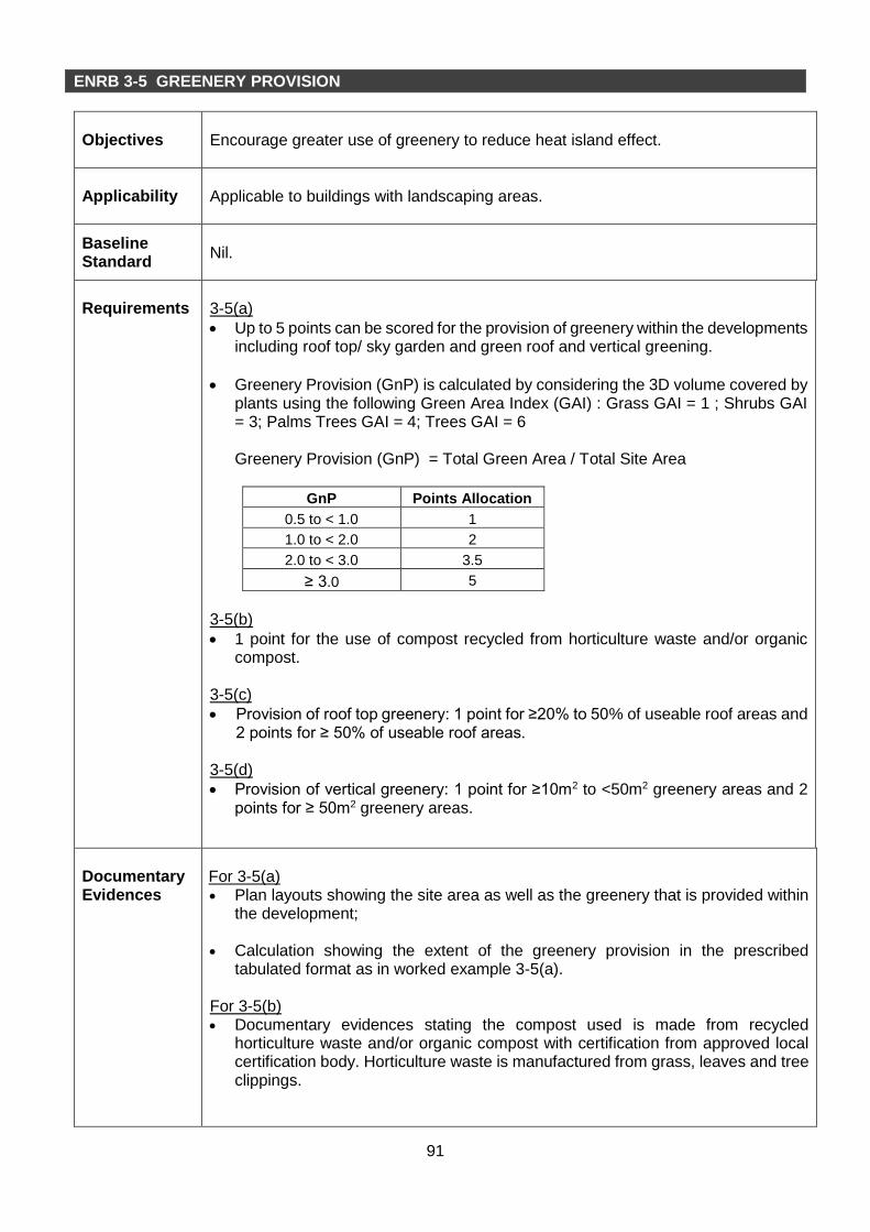
91
ENRB 3-5 GREENERY PROVISION
Objectives
Encourage greater use of greenery to reduce heat island effect.
Applicability
Applicable to buildings with landscaping areas.
Baseline Standard
Nil.
Requirements
3-5(a)
Up to 5 points can be scored for the provision of greenery within the developments including roof top/ sky garden and green roof and vertical greening.
Greenery Provision (GnP) is calculated by considering the 3D volume covered by plants using the following Green Area Index (GAI) : Grass GAI = 1 ; Shrubs GAI = 3; Palms Trees GAI = 4; Trees GAI = 6 Greenery Provision (GnP) = Total Green Area / Total Site Area
GnP Points Allocation
0.5 to < 1.0 1
1.0 to < 2.0 2
2.0 to < 3.0 3.5
≥ 3.0 5
3-5(b)
1 point for the use of compost recycled from horticulture waste and/or organic compost.
3-5(c)
Provision of roof top greenery: 1 point for ≥20% to 50% of useable roof areas and 2 points for ≥ 50% of useable roof areas.
3-5(d)
Provision of vertical greenery: 1 point for ≥10m2 to <50m2 greenery areas and 2 points for ≥ 50m2 greenery areas.
Documentary Evidences
For 3-5(a) Plan layouts showing the site area as well as the greenery that is provided within
the development;
Calculation showing the extent of the greenery provision in the prescribed tabulated format as in worked example 3-5(a).
For 3-5(b) Documentary evidences stating the compost used is made from recycled
horticulture waste and/or organic compost with certification from approved local certification body. Horticulture waste is manufactured from grass, leaves and tree clippings.

92
For 3-5(c) Plan layouts showing the greenery area on the roof top and the calculation of the
percentage area compared to useable total roof area. For 3-5(d) Plan layouts showing the vertical greenery area and the calculation of this area.
References
Nil.
Examples
1) Determine the number of trees, palms and the areas for shrub and turfs and other
greenery area 2) The canopy, radius and Green Area Index are pre-determined design parameters
applicable for all developments. 3) Compute the green areas as shown in the Table 3-5(a) below. Table 3-5(a) – Calculation of the Greenery Provision
Description Qty (A)
Canopy area (B)
Radius (C)
Green Area Index GAI
Green Area (A)x(B)x(C2)xGAI
Trees (Nos) 20 3.14 3.5 6 4615.8
Palms (Nos) 20 3.14 1 4 251.2
Shrubs (m2) 20 NA NA 3 60
Landscape area + Roof garden +
vertical greening (m2)
100 NA NA 1 100
Total Green Area : 5027
Assume site area is 4000m2
Greenery Provision (GnP) = Total Green Area / Total Site Area
= 5027 / 4000
= 1.26 (1.0 to <2.0)
Therefore, points scored for 3-5(a) = 2 points

93
ENRB 3-6 ENVIRONMENTAL PROTECTION
Objectives
To encourage the adoption of sustainable and environmental friendly procurement and purchasing policy in the operation and maintenance of the building and the use of environmentally friendly refrigerant in the air-conditioning system.
Applicability
Generally applicable to all buildings.
Baseline Standard
Nil.
Requirements
3-6(a)
1 point can be scored for the adoption of sustainable and environmental friendly procurement and purchasing policy in the operation and maintenance of the building.
3-6(b)(i)
1 point can be scored for using refrigerants with ozone depletion potential (ODP) of zero and with global warming potential (GWP) of less than 100.
3-6(b)(ii)
1 point can be scored for installing a refrigerant leak detection system at critical areas of the plant rooms with chillers and other equipment with refrigerants.
Documentary Evidences
For 3-6(a) Documentary evidences stating management’s green procurement policy and
extracts of tender specification or quotation for environmental friendly products. For 3-6(b)
Extracts of technical specification or photographs of chiller’s or condensing unit’s name plate that shows refrigerant used for the chillers.
Technical specification and/or drawings/photographs showing the refrigerant leak detection system.
References
Green Procurement Policy The goal of this policy is to reduce the adverse environmental impact of building owners’ purchasing decisions by buying goods and services from contractors and vendors who are committed to environmental sustainability. The following are some strategies for this Policy:- a) Purchase only most up-to-date energy efficient equipment, where applicable. This
includes, but not limited to air-conditioning system, lightings and office appliances.
b) Purchase only readily biodegradable and phosphate free cleaning detergents and products that meet approved certification standards and have eco-labels such as Singapore Green Label Scheme (SGLS).
c) Purchase only bio-based plastic products that are biodegradable and compostable, such as bags, food and beverage containers, and cutlery.

94
d) For building maintenance, purchase products/materials such as paint, carpeting, adhesives and furniture, with the lowest amount of volatile organic compounds (VOCs), highest recycled content, and low or no formaldehyde.
e) For landscape maintenance, to employ landscape contractors who are familiar with sustainable landscape management techniques such as, drip irrigation, composting and use of mulch and compost produced from regionally generated plant debris and/or food waste.

95
ENRB 3-7 GREEN TRANSPORT
Objectives
Promote the use of public transport and environmental friendly transport options to reduce pollution from individual car use.
Applicability
Generally applicable to all buildings.
Baseline Standard
Nil.
Requirements
3-7(a)
1 point can be scored if building has good access (< 500m walking distance) to public transport networks such as MRT/LRT stations and bus stops.
3-7(b)
1 point can be scored for provision of covered walkway to facilitate connectivity and use of public transport.
3-7(c)
1 point can be scored for provision of adequate priority parking lots for hybrid/electric vehicle within the development.
3-7(d)
Up to 1 point can be scored for the provision of covered/sheltered bicycles parking lots with adequate shower facilities. (Minimum provision of 10 bicycle parking lots; cap at 30 bicycle parking lots where applicable) :
- 1 point if the number of bicycles parking lots is ≥ 1% x (GFA/10)
- 0.5 point if the number of bicycles parking lots is ≥ 0.5% x (GFA/10)
Documentary Evidences
For 3-7(a) Site layout plan in the context of the surrounding area showing the location of the
building and the location of the MRT/LRT stations and bus stops. For 3-7(b) Site layout plan showing the connection of covered walkway from the
development to the MRT/LRT stations or bus stops; and Documentary evidences or letter of commitment stating the requirement to provide
covered walkway. For 3-7(c) Documentary evidences or letter of commitment stating the requirement to provide
priority parking lots for hybrid/electric vehicle. For 3-7(d) Documentary evidences or letter of commitment stating the requirement to provide
covered/sheltered bicycles parking lots, shower and changing facilities for the development and the quantity and location of bicycle lots provided. The shower and changing facilities shall be accessible to the cyclists.
References Nil.

96
Worked Example 3-7(d)
Example 1
An existing building has a Gross Floor Areas (GFA) of 12,000 square metres. Minimum number of bicycle parking lots = 1% x (12000/10) = 12 lots (with adequate shower facilities) Minimum number of bicycle parking lots = 0.5% x (12000/10) = 6 lots (with adequate shower facilities) 1 point will be scored if the number of bicycles parking lots provided ≥ 12 lots. 0.5 point will be scored if the number of bicycles parking lots provided ≥ 10 lots with adequate shower facilities. Since the minimum provision of 10 bicycles parking lots is required, no points given if the number of bicycles parking lots provided is < 10 lots.
Example 2
An existing building has a Gross Floor Areas (GFA) of 70,000 square metres. Minimum number of bicycle parking lots = 1% x (70000/10) = 70 lots (with adequate shower facilities) (1 point) Minimum number of bicycle parking lots = 0.5% x (70000/10) = 35 lots (with adequate shower facilities) (0.5 point) 1 point will be scored if the number of bicycles parking lots provided is 30 lots with adequate shower facilities. Note : Cap at 30 bicycles parking lots

97
Part 4 – Indoor Environmental Quality ENRB 4-1 Indoor Air Quality (IAQ)
ENRB 4-2 Indoor Air Pollutants
ENRB 4-3 Lighting Quality
ENRB 4-4 Thermal Comfort
ENRB 4-5 Internal Noise Level
(II) Other Green Requirements

98
ENRB 4-1 INDOOR AIR QUALITY PERFORMANCE
Objectives
Ensure building ventilation systems are designed and installed to provide acceptable IAQ under normal operating conditions.
Applicability
Applicable to all air-conditioned buildings.
Baseline Standard
-
Requirements
4-1(a) Pre-requisite Requirement 4 points can be scored for performing full IAQ audit by an accredited laboratory under Singapore Accreditation Council. Results of audit shall comply with NEA’s Guidelines for Good Indoor Air Quality in Office Premises or SS554:2009 Code of Practice for Indoor Air Quality for Air-conditioned Buildings. 4-1(b) 1 point can be scored for implementing effective IAQ management plan to ensure that building ventilation systems are frequently maintained to ensure clean delivery of air. 4-1(c) 1 point can be scored for the provision of high efficiency air filter (at least MERV 13) in Air Handling Units. 4-1(d) 1 point can be scored for providing Room Temperature display (at least 1 unit per floor). 4-1(e) 1 point can be scored for providing Carbon Dioxide sensor display (at least 1 unit per floor).
Documentary Evidences
For 4-1(a)
IAQ audit results/report by an accredited laboratory. For 4-1(b)
Document or report on the implementation of the IAQ management plan. For 4-1(c)
Technical product information which should include the minimum efficiency reporting value (MERV) parameters of the filters;
For 4-1(d)
Layout plan showing the location of Room Temperature display. For 4-1(d)
Layout plan showing the location of Carbon Dioxide sensor display.

99
References
NEA’s Guidelines for Good Indoor Air Quality in Office Premises
SS 554:2009 - Code of Practice for Indoor Air Quality for Air-conditioned Buildings
IAQ management programme, refer to guidelines given in Annex G of SS554:2009 Code of Practice for Indoor Air Quality for Air-conditioned Buildings.
Air filter classification can be found in Annex E of SS554:2009 Code of Practice for Indoor Air Quality for Air-conditioned Buildings.

100
ENRB 4-2 INDOOR AIR POLLUTANTS
Objectives
Minimise airborne contaminants, mainly from inside sources to promote a healthy indoor environment.
Applicability
Generally applicable to all building developments.
Baseline Standard
Nil
Requirements
4-2(a) 1 point can be scored for the use of low volatile organic compounds (VOC) paints certified under approved local certification body. 4-2(b) 1 point can be scored for the use of adhesives certified by approved local certification body.
Documentary Evidences
For 4-2(a) Layout plans and/or documentary evidences showing areas using the low VOC
paints.
Certification by approved local certification body.
Technical specification of the low VOC paints.
For 4-2(b) Documentary evidences on the use of the adhesives.
Certification by approved local certification body.
Technical specification of the adhesives.
References
Nil.

101
ENRB 4-3 LIGHTING QUALITY
Objectives
To encourage good workplace lighting quality to promote productivity and occupant comfort.
Applicability
Generally applicable to all internal areas.
Baseline Standard
Schedule of lighting requirements stated in SS531:Part 1:2006 or CP 38:1999.
Requirements
4-3(a)
1 point can be scored if the lighting levels comply with SS531 or CP38:1999 for various uses.
4-3(b)
1 point can be scored if at least 90% of occupants are able to control lightings by light switches.
2 point can be scored if at least 90% of occupants are able to control lightings by task lightings.
4-3(c)
Up to 2 points can be scored for the use of high frequency ballasts in the fluorescent lightings if it is adopted in all applicable areas that are served by fluorescent lightings.
20% to < 40% - 0.5 point 40% to < 60% - 1 point 60% to < 80% - 1.5 points 80% and above - 2 points
Documentary Evidences
For 4-3(a) Tabulation of lux level measurements and plan layout showing the location of
the measurements taken.
For 4-3(b)
Tabulation of areas where task lights or light switches are used. For 4-3(c) A summary sheet listing all fluorescent lightings used for the developments and
those with high frequency ballasts.
Technical specification for the high frequency ballasts used in all fluorescent luminaries.
References
CP 38:1999 : Code of Practice for Artificial Lighting in Buildings
SS 531:Part 1:2006 : Code of Practice for Lighting of Work Places Part 1 – Indoor Lighting

102
ENRB 4-4 THERMAL COMFORT
Objectives
To encourage buildings to maintain good indoor conditions for thermal comfort.
Applicability
Generally applicable to all indoor air-conditioned environment.
Baseline Standard
Indoor conditions for comfort air-conditioning as stated in CP 13:1999.
Requirements
4-4(a) 1 point can be scored if the indoor dry-bulb temperature is within 22.5 °C to 25.5
°C and relative humidity <70%. 4-4(b)
1 point can be scored if occupants are able to control the indoor temperature.
Documentary Evidences
Tabulation of temperature and relative humidity measurements and plan
drawings indicating locations of sampled points taken.
Tabulation of areas where temperature can be controlled by thermostats.
References
CP 13:1999 – Code of Practice for Air-Conditioning and Mechanical Ventilation in Buildings.

103
ENRB 4-5 INTERNAL NOISE LEVEL
Objectives
To control and keep the background noise in occupied spaces at levels appropriate to the intended use of the spaces.
Applicability
Generally applicable to all building developments.
Baseline Standard
Recommended ambient sound level in CP 13:1999 or SS 553:2009.
Requirements
1 point can be scored if the occupied spaces in buildings are maintained at the recommended ambient sound levels stated in CP 13:1999 or SS 553:2009.
Documentary Evidences
Tabulation of sound levels measurements and comparison with the recommended sound levels in CP 13”1999 or SS 553:2009.
Plan drawings indicating locations of sampled points taken.
References
CP 13:1999 – Code of Practice for Air-Conditioning and Mechanical Ventilation in Buildings.
SS 553:2009 - Code of Practice for Air-Conditioning and Mechanical Ventilation in Buildings.

104
Part 5 – Other Green Features ENRB 5-1 Green Features and Innovations
(II) Other Green Requirements

114
ENRB 5-1 OTHER GREEN FEATURES
Objectives
Encourage the use of green features which are innovative and have positive environmental impact on water efficiency, environmental protection and indoor environmental quality of the buildings.
Applicability
Generally applicable to all building developments.
Baseline Standard
Nil.
Requirements
Up to 10 points can be scored for the use of the non-energy related green features depending on their potential environmental benefits or reduced environmental impacts. Examples of the green features are:- Water Efficiency (i) Use of self cleaning façade system
2 points for more than 75% of the applicable facade areas 1 point for more than 50% of the applicable facade areas 0.5 point for at least 25% of the applicable facade areas
(ii) Use of grey water recycling system 2 points for all blocks of the development 1 point for at least one block of the development
(iii) Recycling of AHU condensate 1 point for more than 75% of the AHU condensate 0.5 point for at least 50% of the AHU condensate
Environmental Protection (i) 0.5 point for the use of non-chemical termite treatment system such as termite
baiting system, anti-termite mesh.
(ii) 0.5 point for the provision of at least 5 nos. of compost bins to recycle organic waste.
(iii) 0.5 point for the use of non-chemical water treatment system for swimming
pools. (iv) 1 point for the provision of double refuse chutes for separating recyclable from
non-recyclable waste.
(v) Treatment of storm water runoff before discharge to public drains. • 2 points for treatment of run-off for more than 10% of total site area • 1 point for treatment of run-off for up to 10% of total site area
Note: The treatment of storm water runoff shall be through provision of infiltration features or design features as recommended in PUB’s ABC Water design Guidelines.

115
(vi) 0.5 point for use of new generation of refrigerants with ODP =0 and GWP <150.
Indoor Air Quality
(i) 1 point for the use of pneumatic waste collection system.
(ii) Use of Ultraviolet light-C band (UV) emitters in air handling units to improve indoor air quality. 1 point for more than 75% of the AHU have this emitter 0.5 point for at least 50% of the AHU have this emitter
(iii) Use of at least MERV 14 or equivalent – 0.5 point Others
(i) 0.5 point for the use of siphonic rainwater discharge system at roof.
(ii) 0.5 point for the provision of carpark guidance system.
(iii) 1 point for having Green Lease arrangement for building tenants.
(iv) 0.5 points for the use of Titanium Dioxide coating to remove odour in toilets.
(v) 0.5 points for the use of automatic condenser tube cleaning system for the chillers.
(vi) Encourage tenants to take up Green Mark Occupant Centric Schemes (cap at 2 points). 0.5 point for having at least 3 tenant certified under Green Mark
Occupant-Centric Schemes 1 point for achieving Green Mark Pearl Award 2 points for achieving Green Mark Pearl Prestige Award
(vii) Provision of Green Corner, which is an area dedicated to education and
promotion on green and environmental sustainability. It must be located at prominent location/s, where occupants have easy access to it. 0.5 point for having posters and displays on green and sustainability. 1 point for having screen showing the building’s real time energy
performance.
(viii) Install power meters for monitoring of air side system (cap at 2 points). 0.5 point for installing power meters to all air side system and link up to
BMS for ease of monitoring and calculating total system kw/ton. 1 point for achieving 0.28 kw/ton (Total air side system kWh / total cooling
load Rtonh) 2 points for achieving 0.25 kw/ton (Total air side system kWh / total
cooling load Rtonh)
(ix) 1 point for having an energy performance contract with a SGBC accredited Energy Performance Contracting Firm that guarantees the operational system efficiency of a chiller plant. The contract should at least be valid for the next 3 years.
Documentary Evidences
Write-up describing the provision of the green features and the extent of
implementation.

116
Technical product information (including drawings and supporting documents) of the green features;
Details showing the positive environmental impact and benefits that the features
can bring to the building.
References
-