Embed Size (px)
Citation preview
The BASILISCUS Project - Return of the Cruising Hydrofoil Sailboat
Thomas E . Speer, Des Moines, Washington, USA
ABSTRACT
Basiliscus will be a cruising hydrofoil sailboat, muchalong the lines of David Keiper's Williwaw, butincorporating experience that has been gained inmultihull design in the thirty years since Williwaw'sconstruction. This paper covers the development planfor the entire project and the technical results of designstudies performed to date.
Topics covered include scaling laws for modelhydrofoils, the baseline design, and preliminary CFDmodeling of the hydrofoils.
NOTATION
A aspect ratio, b2/SCAD computer aided designCD drag coefficientCDj junction drag coefficientCDLE leading edge drag coefficientCDs spray drag coefficientCDw wave drag coefficientCf skin friction coefficientCFD computational fluid dynamicsCL lift coefficientCp prismatic coefficientD drag, lbFr Froude numberFY side force, lbK scale factorL lift, lbLCB longitudinal center of buoyancyLwl length of waterline, ftL/D lift/drag ratioNj number of junctionsNr number of rungs in ladder foilNs number of surface piercing surfacesOLE object linking and embeddingRTM resin transfer moldingS area, generally, ft2
S hull wetted cross sectional areaS hydrofoil projected planform areaSD drag area, ft2
SDi induced drag area, ft2
SL lift area, ft2
SY side force area, ft2
SMP ship motion programV speed, generallyV, V1, V2 boat speed, ft/secVPP velocity prediction programW weight, lbX longitudinal distance, ftXCB position of LCB forward of
amidshipsa0 sectional lift curve slope, deg-1
aka crossbeam between hullsama outer hullb, b1, b2 span, ftbe effective span, ftc, c1,c2 chord, ftg gravitational acceleration, ft/sec2
n chord scaling exponentp velocity scaling exponentlcb XCB / Lwlt foil thickness, fta angle of attack, deg.a0 angle of attack for zero lift, deg.∇ displaced volume, ft3
Γ dihedral angle, degreesγ course angle to the true wind, degreesρ density, slug/ft3
ξ independent parameter
INTRODUCTION
In the Spring of 1968, David Keiper's Williwawmade her first flight. Williwaw was a 31 ft plywoodtrimaran equipped with aluminum ladder foils (Figure1). Over the next decade, Keiper sailed her extensivelyin the Pacific, ranging from San Francisco to Hawaiiand New Zealand. She was destroyed at anchor inHawaii in 1977 (Keiper, 1996). Although several foil-assisted trimarans have been sailed and raced offshore,to date, Williwaw is the only full-flying hydrofoil tohave proven herself in transoceanic sailing.
Correspondence with Keiper regarding two-dimensional foil sections led to starting on the design of

a complete boat - the Basiliscus Project . This is areport on the early stages of a work-in-progress. It willconcentrate on the planning aspects of the project anddesign requirements.
The basic concept is moderate risk - it's been donebefore. However, it's only been done once, and theconcept is not mature enough to be considered low risk.There are very little empirical data available, and noneat all for sailing hydrofoils of this size. The budget isalso very limited, which rules out tank testing or windtunnel testing to base the design on experimental data.
So the plan of attack is to depend a great deal onmodeling and simulation to explore the basic designparameters and to create a good performing, robustdesign. However, computer modeling alone is notexpected to be accurate or reliable enough, so asubscale, manned prototype will be used to validate thepredictions, gain practical experience with sailinghydrofoils, and to serve as a test bed for investigatingvarious foil arrangements.
Despite the limited budget, money will be spentwhere it can have the most leverage on the total cost.Consulting by a professional boat designer or navalarchitect will bring in offshore experience andstructures expertise and serve as a cross check on theengineering analyses.
Finally, the method for constructing the boat will befactored in as early in the design as possible, andconsiderable effort will be made to ensure that thefabrication will be efficient and as inexpensive aspossible.
REQUIREMENTS
The process for developing the boat starts withdefining clear requirements and priorities. The usage ofthe boat will evolve in three overlapping phases. PhaseI is the experimental phase. During this period, the boatwill be day-sailed to develop the hydrofoils and rig, andto gain experience in sailing a boat of this type. PhaseII will consist of club racing on Puget Sound and
coastal cruising, primarily in the San Juan Islands andalong Vancouver Island. Phase III will consist ofcruising in the Pacific. Although the anticipatedoperating area is the Pacific Ocean, nothing in thedesign should preclude being able to operate worldwide, except for the Southern Ocean.
There is no intention at this time of doing longdistance racing, other than coastal races like theSwiftsure Classic or the VanIsle 360, and racingrequirements will not be a design driver. Given theunusual nature of the boat, it will require specialtreatment in handicapping, so there is little point inwarping the design to optimize its rating.
There are only three hard requirements:
• It must fly,• It must cruise,• It must be affordable.
Everything else will be traded off if it means one ofthese will not be met.
It Must FlyThe ability to fly is the only performance
requirement. There is no specification for how fast theboat has to go. However, it is expected that if theperformance is sufficient to fly in a wide variety ofconditions, that her performance will be satisfactory forcruising and racing.
The purpose of the hydrofoils is to raise the averagespeed of the boat, not necessarily the top speed, withthe philosophy that, "It's not how fast you go, it's howmuch you go fast that counts." Until the velocityprediction program (VPP) is operational, it is notpossible to guess as to what kind of speeds will beobtained and under what conditions. Although the VPPwill be used to maximize the performance of the boat,the object is not to build a 30 knot sailboat. The objectof Basiliscus is to make 20 knots as boring as possible.
The performance goal is to be able to fly towindward. Keiper's Williwaw did not have the stabilityand her second-hand sails were not efficient enough toallow her to fly on courses other than a reach. Beingable to fly to windward will significantly improve thecomfort when beating into a seaway and the ability tofly closehauled will improve her performance whensailing off the wind with the apparent wind wellforward.
Speed is not the only reason for hydrofoils. Theyimprove seaworthiness, too. "Amazingly, thehydrofoils help to cure most of the bad habitsassociated with multihulls, such as: pounding, quickmotion, snap-rolling in beam seas, difficulty in self-steering, the shaking of wind out of the sails, lee-bowburying, and pitchpoling or capsizing in freak waves."(Keiper, 1996). These attributes are due to raising the
Fig. 1, Williwaw sailing at PacificMultihull Association speed trials, 1975

hulls out of the water and away from wavedisturbances, by the increased dampening provided bythe hydrofoils, and through the increased stabilityafforded by widely spaced foil units. The latter arisesfrom the fact that hydrodynamic forces increase withthe square of the speed, while forces from buoyancy areindependent of speed. Thus the boat acquiresadditional stability when it needs it most as it is drivenhard or surfing down waves.
Hydrofoils also allow tailoring of the motions inwaves through their heave stiffness. For fullysubmerged foils this is done through the design of thefeedback control system and for surface piercing foilsby the choice of chord and dihedral, which dictate therate at which the wetted area of the foils change withheight.
Against these advantages must be balanced somesevere drawbacks for hydrofoils. Hydrofoils addweight and complexity. It is important that they beretractable when hullborne to reduce the considerableadded drag due to their wetted area. When retracted,the hydrofoils add windage and may occupy deckspace.
However, the most severe drawback is theirpropensity for collision. Even small debris or seaweedcan cause damage or significantly degradeperformance. And whereas the chances are a collisionwith a modest size object and a hull will be a glancingblow, the hydrofoil leading edge meets everything headon. This is a severe liability for a coastal cruiser wherethe chances of encountering debris is high. Finally,grounding of a foilborne hydrofoil can be a catastrophicevent.
In major collisions, such as with a semi-submergedshipping container, the craft has a good chance ofescaping severe damage because the hydrofoils can bemade to be sacrificial, breaking away and allowing thecraft to decelerate more slowly while the hull passesover top of the object. The hydrofoils may bedestroyed, but the boat has a better chance of avoidingcatastrophic damage.
Therefore, the hydrofoil cruiser may be a nichevehicle, best suited to offshore passage making, wherethe chances of minor collisions are reduced, theavoidance of catastrophic damage is most needed, andwhere the hydrofoil's speed and seaworthiness can be agreater asset.
The need to fly exerts a powerful influence on therest of the design, particularly with respect to the needto keep weight to a minimum, have a powerful efficientrig, to have a structure which is stiff and capable ofhandling the large loads at concentrated points from thehydrofoil attachments, and a hull shape which iscompatible with stable transition to foil borne operationon takeoff. These factors argue for a boat that is
designed from the outset to be a hydrofoil, rather thanadding hydrofoils to an existing boat.
It Must CruiseThe purpose of Basiliscus is to travel long distances
offshore with a crew of one or more. This is not to be astripped-down racer nor a day-sailer like the twocurrent production hydrofoil sailboats, the HobieTrifoiler and the Windrider Rave. Nor is it to be anextreme ocean racing machine in the vein of the Open60 trimarans.
It is to provide simple but "female friendly"accommodations for extended passages. Firmrequirements include standup headroom and anenclosed head. The interior must be habitable whencapsized, and hard points will be built into the cabinsole for hanging hammocks when inverted. Each cabinmust also be equipped with an escape hatch.
Another firm requirement is shoal draft. All foilsshould be retractable to allow mooring in shallow waterand beaching.
Crew size will typically be two to four for cruising.The boat must be capable of being cruised singlehanded. Crews larger than four will only be used whenday-sailing or round-the-buoys racing.
Based on boats with comparable requirements, suchas the Brown Searunner 37, Farrier F-36, Hughes 37C,Shuttleworth Damiana, or Grainger TR40, the lengthwill be between 35 and 40 ft. Also based on similarboats, the empty weight, with hydrofoils, will beapproximately 4000 lb. With cruising payload,including sails and crew, of around 3000 lb., themaximum displacement is targeted at 7,000 lb.
Height of the mast will be limited to 65 ft so as toclear the fixed bridges on the Intracoastal Waterway.
Cruising requirements will also dictate much of therequired equipment. The boat will comply withoffshore racing regulations as a guide to the minimumsafety requirements.
It Must Be AffordableThe earliest decisions tend to have the largest impact
on the final cost. For example, the decision to fly costs$100,000, since this dictates building a new boat asopposed to purchasing an existing one. Therefore, asignificant effort is being placed on doing analyses andplanning at an early stage while delaying the start ofconstruction as long as possible. The object is to spendtime and money wisely at the start of the project so asto get the greatest leverage to reduce the total cost.
Farrier estimates that an F-36 can be built for $90K -$130K (Farrier 1997), and a Contour 44 (40 ft Lwl)production trimaran has a sailaway price around $335K(Chiodi 1998). Assuming that the price scales as
length3 or by the pound, scaling the Contour to 36 ftprovides a production trimaran price of $250K. Itappears that if Basiliscus can be built for $200K intoday's dollars over approximately seven years itsacquisition costs will be affordable. This will requireconsiderable home-building.
Development of the hydrofoils can be expected toincur additional costs which are difficult forecast at thistime. A factor of three will be applied to the estimatedcosts of the hydrofoils to handle these contingencies.Additional foil stock will also be purchased or built atthe outset to improve the economy of scale and providefor spares and configuration changes.
Maintenance, mooring, and other operational costsmust also be factored into the design. The hydrofoiloffers some significant savings in maintenance costs,because the boat can be allowed to dry out on its foils,making the bottom accessible for routine cleaning orrepair without hauling out. Wider beam makesmooring more difficult to find, and more expensive, andmay dictate the maximum beam of the boat. The lengthis being held to less than 40 feet to keep berthing costsin check. The use of exotic materials will be limited,both to reduce building costs and to ensure the boat isrepairable outside of the U.S.
ENGINEERING ANALYSES
The engineering analyses are designed to answer thequestions,
"How fast will it go?""Will the ride minimize seasickness?""What are good shapes for the hulls?""How strong does it have to be?""Will it fly?""Will it be stable in flight?""How much wind is required to fly?""Will it be well balanced directionally?""How much wind does it take to capsize?""Is it susceptible to wave-induced capsize?"
Several key computer programs are being used toanswer these questions.
Multisurf, by Aerohydro, was selected as the primarycomputer-aided design (CAD) geometry engine(Aerohydro, 1998). This program was selected for itsrelational geometry (which makes it highly parametric),its ability to support object linking and embedding(OLE), its built-in hydrostatics capability, and itsaffordability. The OLE capability, in particular, makesit possible to link Multisurf to other engineering toolsso as to integrate and automate many of the design andanalysis processes.
Several computational fluid dynamics (CFD)programs are being used. Michlet, written by LeoLazauskas, is a Mitchell integral wave drag code,
capable of calculating the wave and viscous drag ofslender symmetrical multihulls. It is being used toestimate the hull-borne resistance. It is not capable ofhandling leeway or heel effects. However, the hullforms are well rounded, heel angles will be less thanfifteen degrees, and leeway angles should be smallwith adequate lateral plane area, resulting in very littleof the side force being carried by the hulls and thuslittle induced drag being produced as a consequence.So the Michlet results are expected to be applicablewhen heel angles are accounted for by the relativeimmersion of the hulls.
The workhorse CFD program is CMARC, a variationby Aerologic of the NASA Ames panel code, PMARC(Garrison, 1997). CMARC is a low-order Morinomethod panel code. It is used to calculate forces andmoments on the hydrofoils and will be used toinvestigate rig designs. The principal drawback ofCMARC is that it does not have a free-surfacecapability. However, the program was modified at theauthor's request to include the linear surface boundarycondition corresponding to the infinite Froude numberapproximation. This is adequate for the hydrofoils.
Hydrofoil sections are designed and analyzed usingthe Eppler code (Eppler, 1990), which was for severaldecades the state-of-the-art in the aerospace industry fortwo-dimensional flow around subsonic airfoils. It hasbeen highly validated by comparison with wind tunneland flight tests. Selected H105 Eppler results have alsobeen validated with XFOIL - today's state-of-the-art.
Finally, the US Navy's Standard Ship MotionProgram, SMP, will be modified to compute thedynamic derivatives and added mass for the seakeepinganalysis.
The primary tool for performing simulations andanalyzing the dynamics will be Scilab (Drakos, 1998).This is a public domain program, modeled after Matlab,available from INRIA in France.
Yet to be determined are the tools for structuraldesign and analysis. Programs needed will include acomposite laminate properties code and a finite elementcode.
Velocity Prediction ProgramThe velocity prediction program (VPP) is the starting
point for most of the engineering studies. It will beused to calculate the yacht's performance and to providea steady-state trim solution for the dynamic simulations.
The principal difference between the VPP beingdeveloped and conventional programs is that theBasiliscus VPP solves for the full six-degrees-of-freedom motion equilibrium. This is necessary toproperly trim the forces and moments from thehydrofoils.

Time Domain SimulationThe quasi-steady force modules from the VPP will
be used in a time-domain simulation to analyze thestability in flight and the takeoff characteristics. Thesimulation differs from the VPP in that the VPPrequires the state of the craft to be iterated until a staticequilibrium is reached, while the simulation simplyintegrates the accelerations resulting from anyunbalanced forces to compute the resulting motion.
The simulation will be hosted on Scilab. In additionto being able to create time histories of the motion, thiswill make it possible to generate linear models tocompute the eigenvalues and modes of the motion andperform frequency responses as a prelude to theseakeeping analysis.
Seakeeping DynamicsThe boat will platform small waves but contour large
ones. There will be no switching of modes as a functionof wave height; instead the dynamics will be tuned tothe wave spectra for ocean waves to achieve thisbehavior. Small, high frequency waves should passunder the boat with minimal response. So a keyquestion is how high does the craft have to fly, given itsnatural frequencies and the sea state? Or put anotherway, at what sea state is it likely that it will have totransition from flying to hullborne operation and whatare the probable operational limits of the craft? Howshould the foilborne frequencies and amplitudes betuned to minimize seasickness? These questions haveto be answered with a seakeeping analysis.
Surface piercing foils do well in headseas becausethe orbital motion helps them up and over the waves.As the wave approaches, the orbital motion increasesthe relative velocity of the foil, creating more lift andraising the boat. The bow encounters the increasedorbital motion first, so the boat tends to pitch up to flyover the wave as well.
But surface piercing foils have a problem whenovertaking following seas. As the boat approaches awave crest, it experiences a drop in relative velocity dueto the orbital motion. This causes the boat to tend topitch down and descend into the wave crest. Thesetrends are resisted by the heave stiffness of the surfacepiercing foil. So how much heave stiffness is neededfor stability in larger waves vs. the desire to beinsensitive to smaller waves is an importantconsideration to be answered by the seakeepinganalysis.
The dynamic coefficients for the seakeeping analysisdiffer from the time-domain simulation because theywill be a function of the frequency of motion. Thesewill be estimated for the hulls using SMP. Added massand dynamic coefficients for the hydrofoils will beestimated using handbook methods (Martin, 1963).
The key stumbling block to the seakeeping analysisat present is the transformation of the coefficients to thecenter of gravity. Transforming the forces andmoments to a new reference center is straightforward,but due to their lateral displacement, the outer hulls andhydrofoils are located at different phases in the wavemotion than the main hull. How to handle this phaseinformation in the transformation remains to be workedout.
Once the ensemble coefficients for the whole boatare assembled, they can be substituted into theequations of motion and the transfer functions of theboat's response determined. Multiplying the transferfunctions times the input spectra for the waves yieldsthe response of the craft to regular waves. Theresponse of the craft in a random seaway will beobtained by superimposing the responses for regularwaves of different directions (Hirsch, 1968).
Unique to this seakeeping analysis compared to thatfor ships is the inclusion of aerodynamic forces. Themotion of the craft in waves will include theaerodynamic damping provided by the sails.Aeronautical models for low level turbulence will beused to determine the motion in flat water due torandom gusts in a similar manner to the seakeepinganalysis. This motion can be further superimposed onthe boat's response in a seaway to obtain the completemotion spectrum.
Capsize DynamicsSome conventional multihull strategies for extreme
conditions may not be available to the cruisinghydrofoil. One example is the strategy of retracting thecenterboard or dagger boards to minimize the lateralplane area and allow the craft to slide sideways like araft if struck by a breaking wave, and avoid the rollingmoments that would result from the board resisting thelateral force of the wave.
The hydrofoil boat can be expected to progress fromfoilborne operation to hullborne with the foils down fordamping when conditions worsen. As the situationdeteriorates farther, it is doubtful whether the hydrofoilscan be safely retracted. Therefore, the hydrofoil mustbe capable of surviving extreme conditions with thefoils down.
Keiper found the motion of a hydrofoil in largewaves to be considerably different from the motion of aconventional multihull sailboat, due to the increaseddamping and dynamic stability. So the wave-inducedcapsize dynamics will be analyzed to assess therelative susceptibility of the boat with foils up anddown, and to develop possible strategies for copingwith extreme conditions that are compatible with theunique characteristics of the hydrofoil.
The time domain simulation will be modified to dothis analysis. The modeling of the wave-induced

capsize will follow that of (Meyers and Krushkov,1984).
Structural LoadsOne result of the extensive modeling planned for the
performance and dynamics of the boat is that thesemodels should provide considerable information on theapplied loads. The VPP will provide the static loads onhulls, rig and foils, while the seakeeping analysis willprovide the acceleration spectrum for any point on theboat for determination of dynamic loads.
The initial structural analysis will be based on(Reichard, 1985). More detailed structural analyseswill be contracted out to experts with multihullstructural design experience.
Weight EstimationThe preliminary design is based on statistical weights
for similar craft.
In addition to the top level requirements, a detailedrequirements document is being maintained. This is anoutline which breaks the requirements down to the levelof individual features or equipment. From this will bederived a spreadsheet containing a bottoms-up weightand mass properties estimate.
As the bottoms-up weight estimate is established,each piece will have an estimate of its moment ofinertia, and the mass properties of the boat will also bebuilt up in detail, including moments of inertia.
HALF SCALE PROTOYPE
The state of the art in CFD today still does not allowaccurate estimates to be made in all cases withoutcalibrating the calculations with empirical data. Towtank testing would be useful, but would consume theentire project budget. Instead, a half scale sailingmodel of the cruiser will be built as a prototype.
The purpose of the prototype is to serve as ahydrofoil test bed and to validate performancepredictions. It may also serve to validate handlingqualities and balance. The performance predictions willbe validated by predicting the performance of theprototype configuration in order to validate theprediction process. The same methodology will then beapplied to the full scale article. Strict similarity to thecruiser configuration is not required, however the closerthe test bed is to the cruiser configuration the better,because the results themselves may be scaled up to be across check on the cruiser computations.
An additional purpose of the prototype is to gainexperience in boat building and to experiment withdifferent materials and fabrication methods. Theexperience gained in building the prototype is expected
to pay for itself in improved detailed design of thecruiser and a shorter learning curve in its construction.It is desirable that the prototype use like materials forthe hull and similar hardware for such items as foilattachment points.
The cheapest and fastest way to produce a half scaleprototype is to purchase a used beach cat and modify itto represent the cruiser configuration. The beach catwill be turned into a half scale prototype by building ascaled model of the center hull and extending the akas.The beach cat's rig will be retained, but may berelocated to match the cruiser's balance. Lateralresistance will come from a centerboard or daggerboard in the main hull rather than the dagger boards ofthe beach cat when hullborne. The hydrofoils willprovide the lateral resistance and steering whendeployed.
Prototype ScalingThe cruiser has a sail area of 800 ft2, a length of 36
ft, and displacements of 5000 lb to 7,000 lb. This givesit a displacement/length ratio of 47 to 66 and a Brucenumber of 1.65 to 1.47. A candidate prototype wouldbe a Hobie 18, which has a weight of 400 lb and a sailarea of 240 ft2. Assuming a new 20 ft hull and beamsweigh 300 lb, with a single crew weight of 200 lb, theprototype would have a displacement of 900 lb for adisplacement/length ratio of 50 and a Bruce number of1.60. This is a good match for the cruiser at lightweight. Placing another 200 lb crew aboard results in adisplacement/length ratio of 61 and a Bruce number of1.50, which is representative of the cruiser at a mid toheavy weight.
Hydrofoil ScalingHydrofoils for the prototype are more problematic.
There are two promising avenues for scaling thehydrofoils: Froude scaling and equal foil loading.
The first, Froude scaling, results in hydrofoils thatare geometrically similar to the cruiser's foils andtakeoff speed of the prototype is 70% of the full scalecruiser's. Equal Froude numbers mean that the wavedrag characteristics of the two boats will be as similaras possible and the scaled spanloading results in thesame induced drag/weight ratio as the full scale boat.Thus the hump speed behavior may be similar.However, the subscale foils will be more lightly loadedthan the full scale foils and less susceptible tocavitation. This makes the prototype more robust, butmay not uncover problems with the full scaleconfiguration.
The second, equal foil loading, results in the chord ofthe half-scale model being only one quarter of the chordof the cruiser, but the model has to operate at the samespeeds as the big boat. Since the speeds are the sameand the lift coefficients are the same, the absolute

pressures on the foils will be the same. Thesehydrofoils would have the same susceptibility tocavitation and ventilation as the full scale foils.Naturally, it will be more difficult for the prototype totake off, since its Bruce number is similar to thecruiser's and it has to sail to a higher Froude number.
The major factor that makes this option attractive isthat it would allow the use of aluminum foil extrusionsalready on hand, purchased from the Keiper estate. Fora half scale prototype, the foil chord will be one quarterof the cruiser's chord. Preliminary estimates indicatethat the cruiser's foil chord will be on the order of onefoot, which makes this a good match to the three inchfoil extrusions. Unfortunately, the section shape on theextrusions, approximately a Clark Y, is quite differentfrom the custom foil shapes, such as the author's H105,that will be used on the cruiser. This limits the utility ofthe existing extrusions.
The plan for the prototype will be to start withhydrofoils made from the existing aluminumextrusions, so as to gain experience in building andsailing a hydrofoil. Since ladder foils are being used, itmay be possible to double the number of rungs to gainthe extra area needed to match the Froude scalingspeeds. As time and money permit, Froude scaledhydrofoils will be fabricated and tested on theprototype. This will provide experience in fabricatingcustom hydrofoil units and offer the opportunity toexperiment with candidate materials and processes,which will also be relevant to the full scale boat.
Instrumentation of the prototype will be consistentwith its low cost nature. A hand held anemometer andGPS would provide the means to measure windspeed-boatspeed ratio as well as absolute boat speed. It maybe worthwhile to invest in commercial electronicinstrumentation, since it could later be installed on thecruiser itself.
Testing of the prototype will include generalhandling, and stabilized speed measurements on avariety of headings. Particular attention will be paid tothe behavior of the hydrofoils, liftoff speeds undervarious conditions, and the difference between foilborne and hull borne speeds. Results will be comparedto predictions for the prototype configuration. Anattempt will be made to resolve differences betweenprediction and test data so as to obtain factors that canbe applied to correct the modeling of the cruiserperformance.
CONSULTING SUPPORT
The consulting effort will be divided into two phases;a review of the preliminary design, and detailed designsupport.
Phase I: Preliminary Design Review.The purpose of the first phase is to critique the
preliminary design and to establish a plan for the rest ofthe development effort. The ideal time for this reviewwill be after the VPP is working and some initial tradestudies have been done. At that point, the designshould have some credibility and its generalcharacteristics be known.
The tasks for the initial consulting effort are:
- evaluate the feasibility of the design,- determine the preliminary material selection andscantlings,- define the initial equipment list,- establish common tools, such as CAD system, forfuture collaboration,- estimate probable cost of the boat,- evaluate the development plan and determinenecessary revisions.
This phase of the consulting effort is intended to beshort, and focused on determining the tasks which mustbe completed before the second consulting phase. It isalso intended to inject realism into the design and focusit on practical matters.
Phase II: Detailed design & building plan.The purpose of the second consulting phase is to
complete all the engineering necessary to beginconstruction. The bulk of the consulting effort willoccur in this phase. At this point, the performance anddynamics analyses will be complete, the design willhave gone through several trade studies, and been testedon the subscale prototype. Static and dynamic loadswill be available. Most of the drawings will exist in adigital format.
The tasks for the second consulting effort are:
- check the design calculations,- perform structural analysis using a finite elementanalysis,- revise scantlings,- establish composite layup schedule,- determine fabrication methods and procedures,- generate full size plans and other drawings forconstruction.
The finite element analysis will require the lion'sshare of the resources for this phase. The ability to dosuch an analysis will likely drive the choice ofconsultants. The choice of consultant will depend onthe ability to do the desired analysis, multihullbackground, interest in the project, and price.
In addition to the naval architecture consulting,potential builders will be identified at this time andbrought into the discussions. Considerable designchanges may be required in order to reduce the costs ofbuilding the boat. The objective of the extensive design
analyses is to produce a firm design for which changesduring building will be minimal.
CONSTRUCTION
Planning for the yacht's construction is broken upinto the supporting logistics and the actual fabricationprocess itself.
LogisticsThe purpose of the logistics effort is to address theaffordability of the yacht.
Make-Buy Breakdown. The biggest questionregarding whether to make the part or purchase it is thehull structure itself. The current plan is to have thehulls and akas (cross beams) professionally built, thenfitted out at home. This uses the skill of the builderwhere it counts most; capitalizes on the builder'sfacility with its space, tools, and hazardous wastehandling (spray booth and the like); and avoids payingshop time and labor for the time consuming but simplertask of installing the hardware.
Secondary structure, such as interior joinery, can beconstructed at home. This will primarily consist of flatcomposite sandwich panels, which can be formed andvacuum bagged on a flat table.
The mast will be handled the same way as the hulls -professional construction of the mast itself, and homeinstallation of the hardware.
For the hydrofoils, one possibility is filamentwinding. It appears that it may be possible to build allthe foils using one cambered section and onesymmetrical section, or possibly just one camberedsection, allowing limited series production. Putrusionswere investigated and found to be too expensive.
After filament winding, the next most likely methodof fabricating the foils will be composite hand layup infemale molds. This can be done entirely at home. Allthe foil segments are less than 10 feet long, and thereare many similar pieces, making it feasible to constructthe tooling for limited series production. The plugs willbe machined professionally using numericallycontrolled machinery to ensure a high degree ofaccuracy.
A more expensive but better controlled variation onhand layup is resin transfer molding (RTM). Thisrequires steel tooling for the molds which would haveto be cut using numerically controlled machining.Once the molds are in hand, the equipment for doingRTM is only a few thousand dollars. The highaccuracy of the resulting foil shape and the limitedamount of hand work needed to finish the foils makesthis approach attractive.
If the foils are to be made of aluminum, they willhave to be professionally fabricated. It may be possibleto have dies made for custom extrusions. As a lastresort, the foils will be made of rolled, weldedaluminum plate. However, this is not likely to yield thedesired accuracy in the section profile, and Williwawcontinually experienced problems with fatigue crackingof her welds. In general, composite construction ispreferred over aluminum.
Metal fittings will be avoided throughout where thefunction can be provided by composites. Chainplatesare a good example. Maximum use of composites willhelp to minimize both weight and cost.
Facilities. Under the current plan, the builder'sfacility will be used for construction of the hulls. Thesewill be transported home individually for fitting outunder a bow frame & plastic enclosure. Once the hullsare complete, they will be transported individually backto the boatyard for final assembly and launching. Thissolves the problem of getting a 28 ft wide boat out frombehind the house and transported through the half mileof city to the nearest marina.
Tools. Tooling will be simplified due to the use of aprofessional builder and his facility for the majorconstruction. A flat table with vacuum baggingequipment, basic hand tools, composite materialhandling (resin pumps and the like), and a table sawand band saw for cutting composite core and woodjoinery will be needed. Inexpensive laser pointers orhome-construction type laser tools will be used asreferences for alignment.
Transportation. Transportation of the boat will beeased by transporting the hulls individually. These canbe moved on an ordinary flat bed truck or trailer.
Berthing Location. Berthing of a multihull in PugetSound will take some advance planning, since all themarinas have waiting lists that are years long. Waitinglists will be joined as soon as construction actuallybegins. It may be necessary to find a moorage onVashon or Bainbridge Islands while waiting for a moreconvenient berth on the mainland.
FabricationThe construction planning has two purposes. The
first is to determine what aspects of the design drive thecosts, so that the design can be modified at the earlystages where construction considerations can have thebiggest impact on the cost. The second purpose is toplan the construction process for execution.
Part Fabrication. The design of the boat will beaccomplished using CAD, which opens up somepossibilities over traditional boat building. Shops withnumerical machining capability will be used to cut partsfor the boat, including tooling and composite cores.This may make it possible to provide the builder with

precut pieces, like a kit, with the labor savings makingthe added expense worthwhile. The labor savings areexpected to come from having the pieces readilyavailable for assembly, reduced fitting and rework, anda more accurate hull shape requiring less fairing effort.
Hulls. The builder will be consulted extensivelyand a great deal of design time spent on theconstruction process itself. Features in the hull designwhich are difficult to build will be modified oreliminated. Once construction starts, changes to thedesign will be limited to those which are absolutelynecessary to remove obstacles to getting the boat built,or those which result in a net reduction of the cost ofbuilding.
The materials to be used for the hulls, and thus theconstruction process, will be determined as part of thestructural design and analysis. For planning purposes,the baseline construction will be of CorcelTM foam corewith s-glass skin and local carbon fiber reinforcement.Although cold molded wood, or even wood skinnedsandwich construction is not ruled out. Plywood isunlikely due to the rounded contours. Wood core, suchas Western Red Cedar, is attractive in cost, but may beexcessively heavy. Cylinder mold and constant cambermethods are also unlikely due to their inability toaccurately achieve the desired shape. Accuracy inbuilding is important to realize the performancebenefits of the engineering and to minimize the laborinvolved in constructing the hulls through the use ofCAD/CAM.
Resin infusion will be investigated to see if it is costeffective for this one-off boat. There should beconsiderable progress in this area by the time the boat isbuilt, and a closed molding process of some kind ishighly probable.
Interior. Interior joinery will be sandwich panelsfor lightness. A thin wood veneer may be used on onesurface for aesthetics, with fiberglass for the facingskin.
The current design lends itself to having the centersection of the boat interior, including the centerboardtrunk, flammables locker/cockpit sole, cockpit seats,bulkheads, and berths all constructed as a unitary pieceusing flat panels. If male molds are used, this centersection could be constructed as a unit and used as amajor part of the mold. If female molds are used, thisunit could be dropped into place once the inside skin ofthe shell is laid up.
Spars. A rotating spar will be used unless there is anoverwhelming advantage shown for a fixed spar. Thespar will have a custom section of moderate size,determined by its use as a storm sail. By the time theboat is built, it is likely that carbon fiber costs will havedropped to the point where carbon will be the only realchoice for the spar. This will undoubtedly requireprofessional fabrication. The spar hardware will be
installed at home, although the stays will be fabricatedby a professional rigger.
Hydrofoils. Assuming that the foils are made ofcomposites, either filament wound or laid up,constructing the hydrofoil units will be largely a matterof trimming the prefabricated sections to length andgluing them together. Fairings at the intersections willboth reduce the interference drag and reinforce thejoints. A key requirement for the hydrofoil assembly ishigh accuracy in aligning the foil elements duringassembly. This will require extensive jigging.
Fitting Out. The vast majority of the hardwareinstallation will be done at home using hand tools, andthe author's own semi-skilled labor.
Final Assembly & Launching. Final assembly isanother area where the builder's skill in ensuringaccurate alignment, and the equipment necessary tohandle large awkward hulls, will be of benefit.Depending on the builder's facilities, this may be adifferent boatyard from the one where the hulls wereoriginally constructed.
Weight ManagementA weight management program will be in place
before construction begins. The purpose of the weightmanagement program will be to monitor theconstruction processes for any unanticipated weightgrowth, to ensure that the mass properties remainsuitable for stable flight, and to maintain an awarenessin all participants of the importance of minimizingweight. This will include weighing each article as it isfinished to compare with the predicted weight.Excessive deviations will be cause for modifying theprocesses so as to check the growth before itaccumulates. If necessary, design analyses will beredone and parts changed to ensure that the boat willstill meet the three cardinal requirements - to fly, tocruise, and to be affordable.
SCHEDULE
The Basiliscus Project is a long term effort, and it isexpected that it will take ten years to produce a mature,ocean-going craft. There is no set deadline for itscompletion. The approximate duration for the tasksdiscussed above is shown in the program schedule,Figure 2.
BASELINE DESIGN
The baseline design is a starting point for theengineering analyses. At this time, the emphasis is ondeveloping the design processes and not on exploring

alternatives for the design itself. The final design willundoubtedly be quite different.
Basiliscus will be a trimaran configuration becausethis was the best fit for the hydrofoil arrangement, atrimaran has the most interior space among multihullsthis size and smaller, and because a trimaran has thebest performance in light winds.
The philosophy behind the design is to have a craftthat is a good sailing boat, fully competent to makeocean passages in all conditions without the hydrofoils.Previous hydrofoil designers have often paid littleattention to the hullborne capabilities and suffered froma lack of stability and poor performance. For example,Keiper capsized Williwaw three times due to a lack ofbuoyancy in the amas. She also had poor performancegoing to windward when hullborne with the foils down,and was eventually fitted with a leeboard to providelateral resistance with lower drag than the hydrofoils.
Figure 3 shows the baseline configuration. It is 36feet long on the waterline, 38.9 feet in length overallwith the foils retracted, with a design displacement of7000 lb. Beam between the centerlines of the amas is
25 feet. Beam overall is 27.6 feet with the foilsretracted and 45.8 feet with the foils down. Maximumdraft is 1.8 feet with all foils retracted, 6.2 feethullborne with the flying foils down, and 7.6 feet withthe centerboard down. The amas are 32 feet on thewaterline at a design displacement of 4000 lb, 32.7 feetlength overall, and displace 9460 lb fully submerged, or135% of the design displacement.
The baseline rig is an 80% fractional sloop. Sail areais 800 square feet, with 500 ft2 allocated to the mainand 300 ft2 to the jib. The head of the main is at 61 feetabove the water.
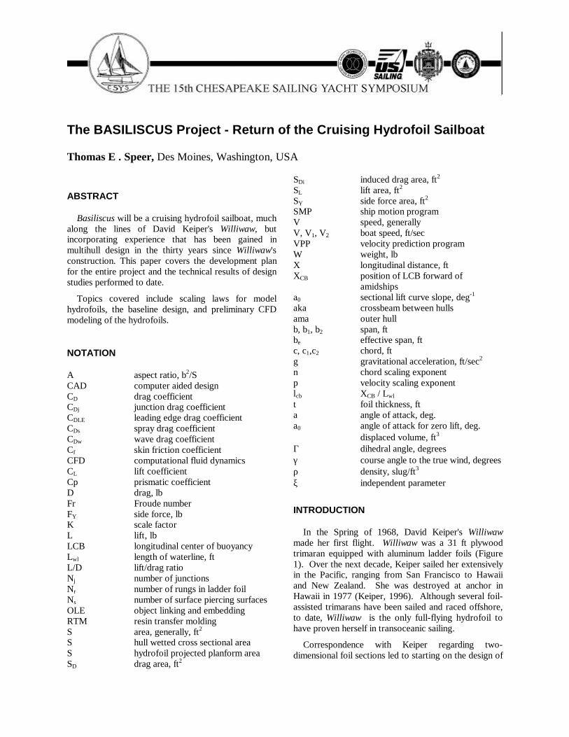
Hull DesignThe hull lines are shown in Figure 4. The main hull
has a prismatic coefficient of 0.6, with an underwaterlength/beam ratio of 10. The prismatic is somewhatlower and the stern finer and more rounded than manymodern trimarans, reflecting a hull optimized forperformance in light winds.
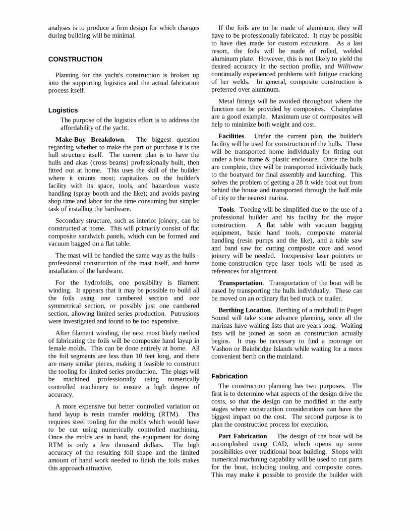
The design cross sectional area distribution is givenby:
Where X is the longitudinal distance along the hull, andS is the cross sectional area. D is the designFig. 3, Trimaran, Foils Down
Fig. 2, Program Schedule
Design
Consultation
Subscale Model
Fabrication Professional
Home
Launch
2000 2001 2002 2003 2004 2005 2006 2007 2008
Preliminary Design Detailed Design
VPP Dynamics
FEM & Design SupportPDR
TestBuildDes.
RigHullsPlanPlan
Fitting OutFoils
1)
2)
X 12
cos ξ( ). l cb 1 cos 2 ξ.( )( ). L wl.
S D
ρ g. L wl.4
πsin ξ( ). 2
π5
8 Cp.( )sin 3 ξ.( ).
2
π3
8 Cp.( )sin 5 ξ.( ).+
....
0 ξ π
displacement, Lwl the design length of the waterline,Cp the prismatic coefficient, and lcb the position of thecenter of buoyancy as a fraction of Lwl forward ofamidships.
The fine entry is a result of the cross sectional areadistribution (Figure 5) and a beam/depth ratio of 0.5 atthe bow. The beam/depth ratio is 1.8 amidships and thesections are very rounded to minimize wetted area.Center of buoyancy is 1% aft of amidships, and themaximum cross sectional area is located 2% aft. Thereis little flare at the waterline to minimize added drag ina seaway.
The narrow stern is a compromise between the needto provide pitch damping while hullborne, minimizingwetted area and wave drag when sailing below hullspeed in lighter winds, and stability on takeoff. Lowrocker and flat, planing sections aft can contribute tounstable pitch-heave coupling. This arises when thesupport provided by the aft sections of the hull drops
off rapidly as the boat rises up on the hydrofoils. Thiscauses the boat to pitch up, increasing the lift on thehydrofoils and accelerating the heave. The result is aboat that shoots up out of the water and then crashesback down. Keeping the hull support centered allowsthe hydrofoils to lift the boat in trim, providing asmooth transition from hullborne to foilborne operation.
Pitching while hullborne is controlled by themovement of the center of buoyancy in the amas andthe main hull, as recommended by Shuttleworth(Shuttleworth, 1998). In addition, the stern foil can bedeployed by itself if needed to provide damping whenconditions warrant, at the cost of some increase inwetted area
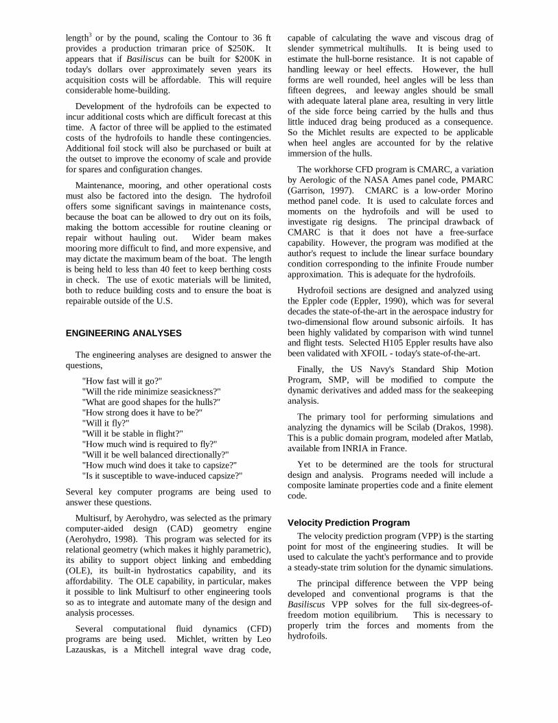
Lateral plane area when hullborne is provided by acenterboard and twin rudders are used for control(Figure 6). The rudders are vertical extensions of thestern foil struts which are immersed when the stern foilis retracted.
The topsides are flared above the waterline toprovide interior space. From the chines at the edge ofthe flare section, the topsides sweep up and across thedeck in a continuous curve. The rounded shape of thesheer is designed to reduce windage. However, a bluffbody realizes most of the possible drag benefit whenthe corner radius reaches 20% of the height (Hoerner,1965). So extremely rounded decks are not necessary.Crown of the foredeck is modest and only a smallportion of the available walking area is sacrificed to theradius at the edges.
The topsides of the amas are similarly shaped so asto provide an area suitable for good footing while beingsufficiently rounded to minimize the windage (Figure4).
The amas can be expected to be out of the water inmoderate conditions, since the boat will be flying then.But they must still provide the necessary stability andseaworthiness under heavy conditions when the boatwill be operated hullborne. Therefore it is not prudentto reduce their size very much relative to a non-flying
Fig. 5, Main Hull Cross Sectional Area Distribution
Fig. 6, Trimaran, Bottom View
Fig. 4, Hull Lines

trimaran. The emphasis on their design can be shiftedmore to robust behavior in heavy conditions withoutbeing too concerned about reducing their drag forperformance in moderate conditions. However, theystill need to allow the boat to efficiently reach itstakeoff speed.
The bottoms of the ama sections are wedge shapedforward. This provides considerable reserve buoyancyand results in the center of buoyancy moving stronglyforward as the ama is immersed so as to reducesensitivity to pitchpoling. This is shown by the middlecurve in Figure 7, which is the difference between thecross sectional area distribution for full immersion(9460 lb) and the design area distribution (4000 lb).Also evident in this figure is the precision to which theactual area distribution meets the design distribution.
The middle sections of the ama are a V'd egg-shapeto reduce wetted area while not being so blunt as topromote pounding and excessively quick roll motions.The aft sections of the amas are wall-sided. Thismaintains a long waterline for moderate immersionswhile not picking up much buoyancy aft when the amasare heavily loaded. Any buoyancy aft under thoseconditions only helps to push the bows down. The aftsections of the amas are also rounded to minimize sideforce, vortex formation and boundary layer separationwith leeway.
The ama lines are designed in a similar manner to themain hull's. A design displacement of 4000 lb wasselected to represent the "catamaran" condition inwhich both hulls are nearly evenly loaded. Theprismatic coefficient was set at 0.65, reflecting theamas' higher design speed, and a similar cross sectionalarea distribution was used.
The akas are one-piece beams extending into theamas nearly to the bottom skin. The center section ofthe amas are cylindrical to facilitate construction andalignment, and the ends are straight tapers that fit intomolded sockets in the amas. This provides a stiff,accurately aligned connection. The akas' shape is wide
and flat on the top to form a wide walkway between thehulls. Their cross sectional shape is that of an airfoilwith a rounded trailing edge to minimize windage.They are placed high in the hull to minimize theirinterference with the interior space and to help the hullfloat out of the water when capsized.
Interior ArrangementThe interior arrangement is patterned after that of the
Brown Searunner series (Brown, 1979). The keyfeatures of this configuration are the central cockpitover the deep centerboard trunk with the mast steppedin the cockpit. Berths are located on each side, fore andaft (Figure 8). The saloon is located in the stern withthe galley just behind the aft companionway.
The aft cabin (Figure 9), is the social center of theboat. It has the saloon in the stern with the galleyimmediately forward. The aft aka intrudes into thegalley, but there is six feet of headroom beneath it andthe area of the galley between the aka and the saloonhas over 6.5 feet of headroom. A well insulated iceboxwill be built under the saloon sole, with the contents ina drawer that pulls out into the galley.
Berths are located port and starboard, extendingunder the cockpit seats. The berths are located near thecenter of gravity to minimize their motion in a seaway.All berths are seven feet long, with the aft berths being31 inches wide and the forward berths 28 inches wide.The aft berths are well suited for lounging, withapproximately four feet of sitting headroom. Eachperson has stowage area for their personal gear locatedunder their berth.
Heavy stores are located to each side of thecenterboard trunk low in the boat and close to the centerof gravity. This maximizes the stability, minimizes themoments of inertia, and limits the range of travel of thecenter of gravity to help ensure stability while flying.The taper of the hull makes the forward end of this areathe preferred location for water tanks, since the openingto the forward cabin is narrower than the region inside.
Fig. 8, Interior Structure
Fig. 7, Ama Cross Sectional Area Distribution

The reverse is true aft, and the stores are more likely tobe needed in the galley than the forward cabin.
A double bulkhead divides the aft berths from theforward berths. This will be vented with a hooded slotlocated on the side of the hull outboard of the cockpitand baffled to form a dorade box. Each berth will havean inspection port opening into this space so that theoccupants can control the ventilation to their ownspace. The slots are located in a region that has highpressure on one side of the boat and low pressure on theother side when the wind is blowing across the boat,promoting a crossflow through the cabin in addition tothe flow through the companion-ways, forward and afthatches, and the saloon's aft port. The inspection portsalso provide access to the sheaves for the steeringcables which will be routed under the berths andthrough the ventilation space to the cockpit.
The forward cabin (Figure 10) is the quiet section ofthe boat, isolated from the social center and designed toallow the off-watch crew to rest undisturbed. Thearrangement of the berths is similar to the aft berths, butwith less headroom - not quite three feet of sittingheadroom is available at the forward bulkhead -although more sitting headroom is available at thecockpit bulkhead. Forward of the aka is the head/wetroom, under the forward hatch. The sail locker is in thepeak forward of the head. Additional sail stowage isavailable in the amas.
The frame at the forward edge of the aka is a majorload point, taking the loads of the aka attachment andthe pivot for the bow foil. The current scheme for theaka attachment has transverse bolts going through earson the akas to the forward bulkhead on each side. Atthe aft center of the aka, horizontal and vertical linksconnect the aka to the hull, with their bolts running foreand aft. This results in a statically determinantconnection to the hull, avoiding internal stresses andfacilitating alignment of the hulls. A tray-like structureis inset into the deck to form a notch for the aka, andthe web forming the aft side of the tray stiffens thestructure to take the loads of the vertical link. Theframe forward of the head picks up the remaining bowfoil attachment point.
The forestay attaches to the aft bulkhead of the chainlocker rather than to the stemhead. This bulkheaddistributes the load into the hull. In conjunction with afolding bow pulpit, this results in a less obstructed entryand exit to the boat when tied bow-on to a quay.Mooring stern-on is not suitable due to the presence ofthe stern foil and its supporting structure.
The center cockpit configuration assures the crewweight will be kept near the center of gravity, sincemost of the time is spent in the cockpit rather thaninside. The proximity of the cockpit-stepped mastmeans that all of the sheets and halyards plus thesteering is close at hand. There is little need for asingle-handed sailor to have to leave the cockpit, andas pointed out by Brown (Brown, 1979), this isespecially true as conditions get worse, ensuring thatthe crew remains safe and protected in the cockpit.
Not visible in the pictures is the flammables locker.The cockpit sole is a grate and underneath on either sideof the centerboard trunk is a well where propane andgasoline will be stored. Fuel for the stove and outboardwill be close at hand but isolated from the living areasof the boat.
Generously sized tubular scuppers, molded into thebottom of the under berth storage areas, will run fromthe wells outboard to the hull. In addition, openings inthe side of the centerboard trunk will allow the cockpitto drain into the trunk. This arrangement ensures thatthe cockpit will stay dry and will empty quickly whenpooped.
Hydrofoil Arrangement The hydrofoils are shown extended in Figure 3 and
retracted in Figure 11. The "diamond" arrangementconsisting of a bow foil, two lateral foils, and a sternfoil was pioneered by Keiper and is ideally suited for asailing hydrofoil. When flying, the windward lateralfoil is completely out of the water.
Figure 12 shows a concept used by Nord Embroden(Embroden, 1987) to analyze the static stability oflandyacht planforms. The idea is to sum up the total
Fig. 9, Aft Cabin
Fig. 10, Forward Cabin

moments in roll or pitch and then represent them as anequivalent movement of the center of gravity (c.g.) inthe horizontal plane. The equivalent c.g. arm isobtained by dividing the moment by the weight. Thisprovides an intuitive measure of stability becausecapsize occurs when the equivalent c.g. reaches theextremes of the vehicle's range of centers of buoyancy,such as the outer hull. The concept is especially usefulfor examining the sideways capsize vs. pitchpolestability of multihulls.
Figure 13 illustrates the concept applied repeatedlyto the Basiliscus configuration and the results overlaidto integrate stability and performance information. Thenominal center of gravity is indicated by the symbollocated near amidships. Since three foils are in thewater, the support is statically determinant and therelative loading of the foils can be estimated for anylocation of the equivalent center of gravity. This isindicated by the grid of straight lines, representing thelinearly dependent nature of the foil loads.
The heavy black curves represent the moments dueto the sail forces at all apparent wind directions and atapparent wind speeds ranging from 10 kt to 30 kt, basedon 800 ft2 of sail area. These curves are based on theMilgram sail force model as presented in (Larsson and
Eliason, 1994). The 25 kt curve just reaches the ama,indicating that when hullborne this is the maximumwind that can be sustained with full sail withoutcapsizing. The 30 kt curve just reaches the center of thelateral foil, indicating that the boat would be justbalanced on the lateral foil under at that condition.
The final set of curves superimposed on the picturecorresponds to hydrofoil performance. The hydrofoilside and resistance forces must equal the forces appliedby the sail. A certain amount of drag is incurred justsupporting the weight of the craft. This is representedby a lift/drag ratio. An additional drag is incurred asthe foils generate side force, and the incremental dragfor each pound of side force was arbitrarily assumed tobe twice that due to a pound of vertical lift on the basisthat the depth of the hydrofoil is typically less than thespan. With these assumptions, the dashed linesrepresenting the moments due to sail forces required toovercome the hydrofoil drag and side force were plottedfor a range of hydrofoil lift/drag ratios.
The resulting picture establishes an excellent idea ofthe hydrofoil requirements. For example, it is clear thatthe craft is not likely to fly in apparent winds much lessthan 15 kt, no matter how efficient the hydrofoils are.If the hydrofoils have a lift/drag ratio (L/D) of at least12:1, the craft could fly at 15 kt, but only with the netsail force pointing straight ahead, which wouldprobably correspond to sailing off the wind a littlebelow a beam reach. With 20 kt of apparent wind, thecraft could fly with hydrofoils with an 8:1 L/D, andcould fly to windward if the hydrofoils had an L/D of12 or above.
In terms of pitchpole stability, the 30 kt curve justreaches the line for zero load on the stern foil. Anyadditional moment results in the stern foil carrying adown load. It is important, therefore, that the stern foilbe designed for negative lift coefficients as well aspositive lift. It is also apparent that the stern foil isunlikely to carry more than one third of the weight.However, it must be able to do so at the comparativelylow speeds corresponding to takeoff in marginalconditions.
Finally, this analysis makes certain designoptimizations straightforward. The diamond hydrofoilarrangement is seen to decouple the pitch and heavecharacteristics from the roll balance. The longitudinallocation of the lateral foil was chosen to maximize theroll stability in high winds, and it is also positioned sothat the relative proportion of the loads carried by thebow and stern foils remains about the same as theheeling moment increases. When hullborne at lowangles of heel, both lateral foils are in the water andcontributing lift. However, this lift is near and ahead ofthe physical center of gravity so the effect of a changein support from the lateral foils as the vehicle rises up isa small but stabilizing (bow down) change in thepitching moment.
Fig. 11, Trimaran, Foils Retracted
Fig. 12, Equivalent CG Concept

The most unsatisfactory aspect of the baseline designis the stern foil (Figure 14). The stern foil must rotateabout the vertical axis for steering and a horizontal axisfor retraction. The transverse axis is currently selectedfor retracting the foil, allowing the foil to rotate forwardand aft. Besides retracting the foil, this freedom ofmotion also allows the pitch of the stern foil to beadjusted.
A fully submerged foil provides the most stability.Such a foil would be the sole determinant of the pitchof the craft when flying because pitch is the only degreeof freedom available for the stern foil to reachequilibrium with its applied loads. The heave of themain hull would then be determined by the bow foil.So it is more important that the stern foil incidenceangle be adjustable than it is for any other foil.
To avoid interference with the hull, the verticalsupport has been divided into two struts, forming aninverted "π" foil. Preliminary calculations indicatedthat the required area could not be practically achievedwith a single element of the same chord as used for thebow and lateral foil ladders, requiring the addition oftwo more elements. These have been arranged in an"X" configuration to provide for a smooth variation inarea as they broach the surface and to brace the strutsdiagonally to stiffen them against side loads.Horizontal ladder rungs could lead to a limit cycleoscillation as the lift on the stern foil changed indiscrete steps unless the rungs were closely spaced sothat the heel angle alone was sufficient to causesuccessive rungs to overlap.
Fig. 13, Hydrofoil Balance
Fig. 14, Stern View
-15
-10
-5
0
5
10
15
20
25
30
-30-25-20-15-10-5051015202530
-20% -10%0%10%20%30%40%50%Stern Foil Load
120%
100%
80%
60%50%
Bow Foil Load
0%
20%
40%
Lateral Foil Load50%40%
20%
0%
60%
80%
100%
Foil L/D
4:1
12:110:1
8:1
6:1
20:1
10kt15kt
20kt
25kt
30kt

These design aspects drive the stern foil support tobe a large truss. The truss is heavy, ugly, produceswindage, and could be susceptible to large loads whenbeing pooped. This was the configuration Keiper usedon Williwaw and the author has tried unsuccessfully tofind a suitable alternative configuration. The truss willbe much wider and more unwieldy on Basiliscuscompared to Williwaw because of the wider aft cabin.
In addition, the cross elements do not allow the sternfoil to rotate forward of the retracted position, whichinhibits the rudders from kicking back when grounded.So shoal waters will have to be negotiated with thestern foil down - not a very palatable prospect. Shoaldraft can be obtained by shortening the rudders, as wasdone on Williwaw. Keiper found his shallow rudderslacked adequate control under some conditions. Otheralternatives are being investigated, including thepossibility of a fixed (but retractable) stern foil andseparate steering or using kick-up rudders in the amas.
HYDROFOIL DESIGN TRADE STUDIES
Hydrofoil Section DesignThree two-dimensional hydrofoil sections have been
investigated. These are the NACA 63-209, EpplerE817, and the author's H105 design. These are shownin Figure 15. The NACA 63-209 has a thickness of 9%of the chord, the Eppler E817 11%, and the H10512.5%.
The NACA 63-209 is one of the 6-series laminarflow airfoil sections designed by the National AdvisoryCommittee on Aeronautics during World War II. The6-series airfoils were designed to produce a uniformvelocity from the leading edge back to a specifiedlocation (given by the second number in thedesignation), and then a linear decrease in velocity tothe trailing edge - the recovery region. This flat"rooftop" velocity distribution can be seen in the uppersurface velocities at three degrees angle of attack(relative to the zero lift line) and in the lower surfacevelocities at one degree angle of attack (Figure 16).
In between these limits, the section has a favorablepressure gradient back to the beginning of the recoveryregion, promoting laminar flow and creating the lowdrag "bucket" characteristic of its drag polar. Aconstant velocity distribution is also of value in ahydrofoil because cavitation occurs when the localpressure falls below a limiting value, and the constantvelocity distribution minimizes the maximum velocityand thus the potential for cavitation.
Bringing the constant velocity clear to the leadingedge creates a problem, however, because at angles ofattack above the design condition the velocity peaksvery strongly at the leading edge, as can be seen by thedistribution for 7 degrees angle of attack (Figure 16),where the local velocity is more than double thefreestream velocity. The rapid deceleration followingthis peak promotes boundary layer separation. And thehigh velocities themselves promote cavitation.
The Eppler E817 section was specifically designedfor use as a hydrofoil (Eppler, 1990). Preventingcavitation over as wide a range of operation as possiblewas the key design requirement. This section also has avery long flat rooftop velocity distribution, as can beseen at its upper surface design condition of 5 degreesangle of attack and lower surface design condition of 1degree angle of attack (relative to the zero lift line).The velocity distribution is rounded somewhat at the
Fig. 15, Hydrofoil Section Shapes
Fig. 16, NACA 63-209 Velocity Distribution

leading edge which reduces the formation of the leadingedge suction peak compared to the NACA 63-209(Figure 17). The slightly concave recovery region ismuch shorter and steeper than that of the NACA 63-209and the section has a significant amount of aft loading.This results in a hooked, under-cambered trailing edge.
The Eppler E817 was not intended for use at lowReynolds numbers, such as might be experienced by thesubscale prototype, where laminar separation must beconsidered. At 12 kt, a three-inch wide hydrofoilwould be operating at a Reynolds number of 360,000,while a one-foot chord operating at 17 kt would have aReynolds number of 2,000,000. So a new section wasdesigned to perform well at Reynolds numbers as lowas 250,000 while still having low drag and minimalsusceptibility to cavitation.
The new section was designated the H105, the Hindicating it was designed for use as a hydrofoil and thenumber being arbitrary. It takes a completely differentapproach to either the E817 or NACA 63-209. Insteadof a flat roof-top followed by an abrupt transition to therecovery region, the upper surface velocity distributionhas a shallow adverse pressure gradient to a wellrounded transition, turning the entire surface into aboundary layer transition ramp (Figure 18). Sincelaminar separation is unavoidable at low Reynolds
numbers, this velocity distribution ensures that thelaminar separation region will reattach in a shortdistance as a turbulent boundary layer, and that theposition of this separation bubble will move smoothlyforward as the angle of attack increases, providing aturbulent boundary layer for a robust pressure recovery.The velocity distribution is also more rounded at theleading edge than the E817, reducing the leading edgesuction peak even more and making for a moreforgiving section. The H105 has less aft loading thanthe E817, resulting in a front-loaded section with anear-constant load over much of the chord.
Figure 19 shows the lift curves predicted by theEppler airfoil analysis code for the three sections athree Reynolds numbers: 250,000, 1,000,000 and3,000,000. All of the sections have a sharp stall,indicative of leading edge separation. The H105 highlift characteristics were intentionally traded off in favorof cavitation resistance, however, it still has a highermaximum lift than the other two.
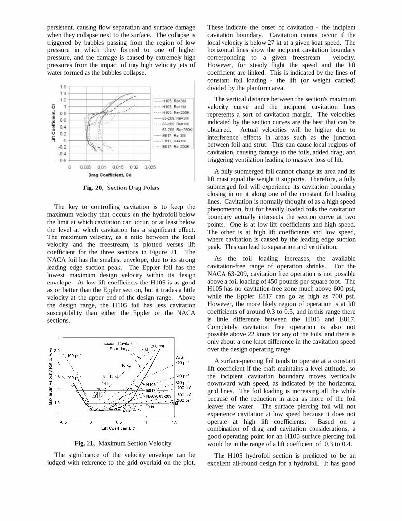
The drag polars for the same three Reynolds numbersand all three foils are shown in Figure 20. Compared tothe NACA section, the low drag bucket of the modernsections is nearly doubled in width. At the highestReynolds numbers, all three sections have essentiallythe same drag at a lift coefficient of 0.2, and the Epplersection's profile drag actually decreases towards itsupper design range. The H105 section has a morerounded drag bucket but with near constant profile dragacross the center as a result of the laminar to turbulenttransition point moving forward on the upper surfacewhile simultaneously moving aft on the lower surface,thus maintaining nearly the same total amount oflaminar flow.
Cavitation occurs when the local pressure on the foilsurface drops below the vapor pressure of water,causing the water to boil and form bubbles in the flow.At the lowest speed at which this can occur, theincipient cavitation speed, the bubbles are microscopicand quickly collapse without effect. As the speedincreases, the bubbles become larger and more
Fig. 17, Eppler E817 Velocity Distribution
Fig. 18, H105 Velocity Distribution
Fig. 19, Section Lift Curves
persistent, causing flow separation and surface damagewhen they collapse next to the surface. The collapse istriggered by bubbles passing from the region of lowpressure in which they formed to one of higherpressure, and the damage is caused by extremely highpressures from the impact of tiny high velocity jets ofwater formed as the bubbles collapse.
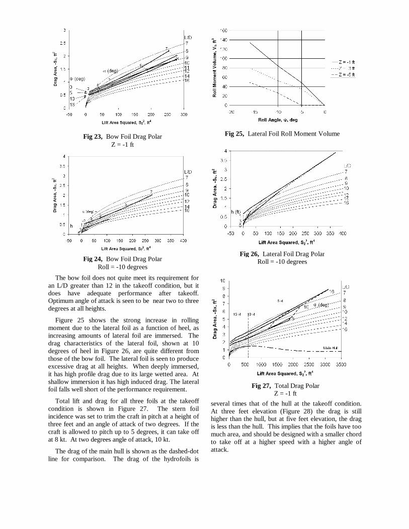
The key to controlling cavitation is to keep themaximum velocity that occurs on the hydrofoil belowthe limit at which cavitation can occur, or at least belowthe level at which cavitation has a significant effect.The maximum velocity, as a ratio between the localvelocity and the freestream, is plotted versus liftcoefficient for the three sections in Figure 21. TheNACA foil has the smallest envelope, due to its strongleading edge suction peak. The Eppler foil has thelowest maximum design velocity within its designenvelope. At low lift coefficients the H105 is as goodas or better than the Eppler section, but it trades a littlevelocity at the upper end of the design range. Abovethe design range, the H105 foil has less cavitationsusceptibility than either the Eppler or the NACAsections.
The significance of the velocity envelope can bejudged with reference to the grid overlaid on the plot.
These indicate the onset of cavitation - the incipientcavitation boundary. Cavitation cannot occur if thelocal velocity is below 27 kt at a given boat speed. Thehorizontal lines show the incipient cavitation boundarycorresponding to a given freestream velocity.However, for steady flight the speed and the liftcoefficient are linked. This is indicated by the lines ofconstant foil loading - the lift (or weight carried)divided by the planform area.
The vertical distance between the section's maximumvelocity curve and the incipient cavitation linesrepresents a sort of cavitation margin. The velocitiesindicated by the section curves are the best that can beobtained. Actual velocities will be higher due tointerference effects in areas such as the junctionbetween foil and strut. This can cause local regions ofcavitation, causing damage to the foils, added drag, andtriggering ventilation leading to massive loss of lift.
A fully submerged foil cannot change its area and itslift must equal the weight it supports. Therefore, a fullysubmerged foil will experience its cavitation boundaryclosing in on it along one of the constant foil loadinglines. Cavitation is normally thought of as a high speedphenomenon, but for heavily loaded foils the cavitationboundary actually intersects the section curve at twopoints. One is at low lift coefficients and high speed.The other is at high lift coefficients and low speed,where cavitation is caused by the leading edge suctionpeak. This can lead to separation and ventilation.
As the foil loading increases, the availablecavitation-free range of operation shrinks. For theNACA 63-209, cavitation free operation is not possibleabove a foil loading of 450 pounds per square foot. TheH105 has no cavitation-free zone much above 600 psf,while the Eppler E817 can go as high as 700 psf.However, the more likely region of operation is at liftcoefficients of around 0.3 to 0.5, and in this range thereis little difference between the H105 and E817.Completely cavitation free operation is also notpossible above 22 knots for any of the foils, and there isonly about a one knot difference in the cavitation speedover the design operating range.
A surface-piercing foil tends to operate at a constantlift coefficient if the craft maintains a level attitude, sothe incipient cavitation boundary moves verticallydownward with speed, as indicated by the horizontalgrid lines. The foil loading is increasing all the whilebecause of the reduction in area as more of the foilleaves the water. The surface piercing foil will notexperience cavitation at low speed because it does notoperate at high lift coefficients. Based on acombination of drag and cavitation considerations, agood operating point for an H105 surface piercing foilwould be in the range of a lift coefficient of 0.3 to 0.4.
The H105 hydrofoil section is predicted to be anexcellent all-round design for a hydrofoil. It has good
Fig. 20, Section Drag Polars
Fig. 21, Maximum Section Velocity

thickness for structural strength, low minimum drag, awide minimum drag range, good behavior outside thedesign range, is highly cavitation resistant, and canoperate at low Reynolds numbers.
The other conclusion is that for a practical designhaving foil/strut junctions, etc., any speed above 18 - 20kt will have some degree of cavitation present.
Baseline Hydrofoil CFD StudiesThe general hydrofoil balance and system
performance requirements were shown in Figure 13.The lateral foil must be designed to take from 0% to100% of the total weight (7000 lb), and will operate inthe vicinity of 50% of the weight for apparent windspeeds between 20 and 25 kt. The bow foil willgenerally carry 20% to 60% of the weight. The sternfoil is more lightly loaded when flying, carryingapproximately 20% of the weight, but must be capableof producing negative lift to avoid pitchpole. The foilsin aggregate must have a lift/drag ratio of 12 or more tomeet the goal of flying to windward. A generichydrofoil trade study identified induced drag as themost important component for drag reduction, andestablished the ladder foil and inverted T foil as themost promising types.
The next step was to examine the baseline hydrofoilconfiguration. This was done using the Cmarc panelcode. Multisurf was used to determine the intersectionsbetween the hydrofoil elements and the water surface,and patch files were output for each surface. Thesewere assembled to create a Cmarc input deck for eachcombination of hydrofoil unit, heave, and roll. Thepanel code models varied from 500 panels to over 5000panels, depending upon the degree of immersion.Straight wakes aligned with the freestream were usedwith no roll-up.
Each hydrofoil unit was evaluated at hull verticaldisplacements of one, three, and five feet and rollattitudes of zero, five, ten, and 16 degrees. Eight runswere made for each to establish the basic lift and dragand the derivatives with respect to angle of attack,sideslip, pitch rate, roll rate, and yaw rate. The basiccoefficients and lift and drag derivatives will be used inthe VPP. These data plus the angular rate derivativeswill be used in the dynamic analyses.
Figure 22 shows some of the panel code models andthe resultant local velocities. Quite visible are theregions of elevated velocity near the intersections.These are the areas which will be affected first bycavitation. Also evident is the highly nonuniformloading of the lateral foil elements, leading tounexpectedly high induced drag.
The highly variable geometry as a function of theoperating condition has required a different approach tobuilding the tables of aerodynamic coefficients. Insteadof tables of lift, drag and sideforce coefficients, lift,
drag and side force areas are used instead. These areasare defined as:
A similar approach is taken with moments, yieldingeffective volumes about each axis.
Although dimensional, with units of ft2, they can betreated much like nondimensional coefficients. A goodexample is the estimation of the effective span, be fromthe slope of a plot of SD vs. SL
2:
Once the effective areas and volumes are computedfor a given configuration, they will be sized linearlywith the chord to adjust them for best performance.More extensive geometry changes, such as changing thespan or the number of elements will require freshcomputation using the panel code.
Preliminary results of the panel code analysis areshown in Figures 23 through 28. The axis conventionadopted throughout the Basiliscus project is X positiveforward, Y positive starboard, and Z positive down,referenced to amidships, design waterplane centerline.So lift in the upward direction is a negative Z force anddrag produces a negative force in the X direction.
The bow foil lift and drag as a function of roll andangle of attack at the takeoff height of one foot isshown in Figure 23. The straight lines on the drag areavs lift area-squared plot show that the induced dragfollows the classical parabolic drag polar, as expectedbased on the linear aerodynamics of the panel code.Figure 24 shows the bow foil lift and drag for the bowfoil at 10 degrees of heel as a function of height andangle of attack.
3)
4)
5)
6)
7)
8)
S LLq
C L S.
S DDq
C D S.
S YF Yq
C Y S.
C DiC L
2
π AE
S DiS L
2
π b2 E..
b e b E.S L
2
π S Di.S L2
2 S L12
π S D2 S D1.

Fig. 22, Foil Surface Velocity RatiosZ = -3 ft, Roll = -10 degrees, Alpha = 2 degrees
Bow Foil
Lateral Foil
Stern Foil
The bow foil does not quite meet its requirement foran L/D greater than 12 in the takeoff condition, but itdoes have adequate performance after takeoff.Optimum angle of attack is seen to be near two to threedegrees at all heights.
Figure 25 shows the strong increase in rollingmoment due to the lateral foil as a function of heel, asincreasing amounts of lateral foil are immersed. Thedrag characteristics of the lateral foil, shown at 10degrees of heel in Figure 26, are quite different fromthose of the bow foil. The lateral foil is seen to produceexcessive drag at all heights. When deeply immersed,it has high profile drag due to its large wetted area. Atshallow immersion it has high induced drag. The lateralfoil falls well short of the performance requirement.
Total lift and drag for all three foils at the takeoffcondition is shown in Figure 27. The stern foilincidence was set to trim the craft in pitch at a height ofthree feet and an angle of attack of two degrees. If thecraft is allowed to pitch up to 5 degrees, it can take offat 8 kt. At two degrees angle of attack, 10 kt.
The drag of the main hull is shown as the dashed-dotline for comparison. The drag of the hydrofoils is
several times that of the hull at the takeoff condition.At three feet elevation (Figure 28) the drag is stillhigher than the hull, but at five feet elevation, the dragis less than the hull. This implies that the foils have toomuch area, and should be designed with a smaller chordto take off at a higher speed with a higher angle ofattack.
Fig 23, Bow Foil Drag PolarZ = -1 ft
Fig 24, Bow Foil Drag PolarRoll = -10 degrees
Fig 25, Lateral Foil Roll Moment Volume
Fig 27, Total Drag PolarZ = -1 ft
Fig 26, Lateral Foil Drag PolarRoll = -10 degrees
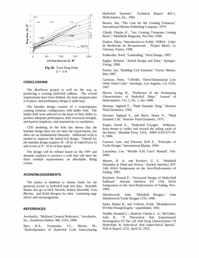
CONCLUSIONS
The Basiliscus project is well on the way toproducing a cruising hydrofoil sailboat. The overallrequirements have been defined, the basic program planis in place, and preliminary design is underway.
The baseline design consists of a contemporarycruising trimaran configuration with ladder foils. Theladder foils were selected on the basis of their ability toproduce adequate performance, their structural strength,mechanical simplicity, and insensitivity to ventilation.
CFD modeling of the foils has shown that thebaseline design does not yet meet the requirements, butthere are no fundamental obstacles. Additional work isneeded to improve the lateral foil design. Takeoff forthe baseline design requires 18 - 20 kt of wind (Force 5)and occurs at 9 - 10 kt of boat speed.
The design will be refined based on the VPP anddynamic analyses to produce a craft that will meet thethree cardinal requirements: an affordable, flyingcruiser.
ACKNOWLEDGEMENTS
The author is indebted to Hanno Smits for hisgenerous access to hydrofoil tank test data. Heartfeltthanks also go to Dick Newick, Robert Downhill, TomBlevins, and Keith Burgess for their continuing sageadvice and encouragement.
REFERENCES
Aerohydro, "Multisurf General Reference," Aerohydro,Inc., Southwest Harbor, ME, USA, 1998.
Barr, R.A., Vermeulen, J.C., Martin, M.,"Hydrodynamics of Hydrofoil Craft Subcavitating
Hydrofoil Systems," Technical Report 463-1,Hydronautics, Inc., 1963.
Brown, Jim, "The Case for the Cruising Trimaran,"International Marine Publishing Company, 1979.
Chiodi, Charles K., "Are Cruising Trimarans ComingBack?," Multihulls Magazine, Nov/Dec 1998.
Drakos, Nikos, "Introduction to Scilab," INRIA - Unite'de Recherche de Rocquencourt - Project Meta2, LeChesnay, France, 1998.
Embroden, Nord, "Landsailing," Nord Design, 1987.
Eppler, Richard, "Airfoil Design and Data," Springer-Verlag, 1990.
Farrier, Ian, "Building Cost Estimate," Farrier Marine,May 1997.
Garrison, Peter, "CMARC Three-Dimensional LowOrder Panel Code," Aerologic, Los Angeles, CA, USA,1997.
Hirsch, Irving H., "Prediction of the SeakeepingCharacteristics of Hydrofoil Ships," Journal ofHydronautics, Vol. 2, No. 1, Jan. 1968.
Hoerner, Sighard F., "Fluid Dynamic Drag," HoernerFluid Dynamics, 1965.
Hoerner, Sighard F., and Borst, Henry V., "FluidDynamic Lift," Hoerner Fluid Dynamics, 1975.
Keiper, David A.., "Hydrofoil Voyager: Williwaw,from dream to reality and toward the sailing yacht ofthe future," Hinsdale Press, USA, ISBN 0-931375-29-0, 1996.
Larsson, Lars, and Eliasson, Rolf E., "Principles ofYacht Design," International Marine, 1994.
Lazauskas, Leo, "Michlet 6.05 User's Manual", Feb.2000.
Meyers, H. A., and Kruskov, U. S., "MultihullDynamics in Wind and Waves," Ancient Interface XIV14th AIAA Symposium on the Aero/Hydronautics ofSailing, 1985.
Reichard, Ronnal P., "Structural Design of Multi-HullSailboats" Ancient Interface XV 15th AIAASymposium on the Aero/Hydronautics of Sailing, Nov.1984.
Shuttleworth, John, "Multihull Designs," JohnShuttleworth Yacht Designs LTD, 1998.
Smits, Hanno B., and Verkerk, Freek, "ModelproevenFD Met Draagvleugels," unpublished, 1981.
Wadlin, Kenneth L.; Shuford, Charles L. Jr.; McGehee,John R., "A Theoretical And ExperimentalInvestigation Of The Lift And Drag Characteristics OfHydrofoils At Subcritical And Supercritical Speeds,"NACA Report 1232, April 22, 1952.
Fig 28, Total Drag PolarZ = -3 ft


![THE PROJECT FOR DEVELOPMENT OF THE …– 1 – 1. Outline of the Project (1) Basic information of the Project [Project Title] Project for Development of the National Biodiversity](https://img.dokumen.tips/doc/110x75/5fbda6715d0d73578e297d3e/the-project-for-development-of-the-a-1-a-1-outline-of-the-project-1-basic.jpg)