Embed Size (px)
Citation preview

R. STAHL explosion protection
The basics of
explosion protection

R. STAHL explosion protection

R. STAHL explosion protection
prefaceIt is a fact that gases, vapours and mists escape during the production, processing,
transportation, and storage of flammable substances in the chemical and petrochemical
industries, as well as during the production of mineral oil and natural gas, in mining and in
many other sectors. During many processes, especially in the food industries, combustible
dusts are also created. These flammable gases, vapours, mists, and dusts form an explosive
atmosphere with the oxygen in the air. If this atmosphere is ignited, explosions take place,
which can result in severe harm to human life and property. To avoid the danger of
explosions, protective specifications in the form of laws, regulations, and standards have
been developed in most countries, which are aimed at ensuring that a high level of safety is
observed. Due to the growing international economic link, extensive progress has
been made in harmonizing regulations for explosion protection. The conditions for a
complete harmonization were created in the European Union through the 94/9/EC and 99/92/EC
Directives. There are also efforts to achieve a global harmonization with the IECEx-scheme,
but much work still needs to be done in this area world-wide. The aim of
this brochure is to provide both experts and interested laymen with an overview of the field
of explosion protection, in conjunction with electrical apparatus and installations. It does
not replace the study of the relevant statutory regulations and applicable standards.
In mining, miners underground have always lived under the threat of firedamp explosions.
Herein lies the origins of explosion protection, which has been consistently developed
in industrialized countries, and which now provides a high level of safety.

R. STAHL explosion protection
contents
Statutory Regulations and Standards
3.1 World-wide 3.1.1 General 3.1.2 Devices 3.1.3 Erection and operation 3.1.4 IECEx3.2 European Union 3.2.1 Directives 3.2.2 Standards 3.2.3 Erection and operation 3.2.4 Selection of devices3.3 North America 3.3.1 General 3.3.2 Erection and operation 3.3.3 Selection of devices3.4 Russia 3.4.1 General 3.4.2 Erection and operation 3.4.3 Selection of devices
Technical Principles
4.1 Zone classification 4.2 Categories and Equipment Protection Level EPL 4.2.1 General
1 Preface
The Basic Physic Principles and Definitions 2
3
4
2
6
9
9999
1112121213131515151618182819
20
202121

R. STAHL explosion protection
6.1 Safety Characteristics of Flammable Gases and Vapours6.2 Constructional Requirements for Explosion Protected Electrical equipment for gas-atmospheres6.3 Degrees of Protection according to IEC 60529 – IPXX6.4 Degrees of Protection according to NEMA Standards
Literature
36373739
44
232324242424252530323334
6
7
5.1 Duties of Installer, Manufacturer and Employer 5.2 Classification of Zones and Selection of Apparatus5.3 Methods of Installation 5.4 Maintenance
5
4.2.2 Categories 4.2.3 Equipment protection level EPL4.3 Groups 4.3.1 General 4.3.2 Classification4.4 Ignition temperature and temperature classes 4.4.1 General 4.4.2 Explosive gases 4.4.3 Combustible dusts4.5 Types of protection 4.5.1 Applications of Type of Protection »Intrinsic Safety« 4.5.2 Applications of Type of Protection »c« 4.5.3 Application and Combination of Types of Protection »d« and »e«4.6 Marking
40
4041434343
Installation and Operation of Electrical Equipment 36
Appendix
2122

R. STAHL explosion protection
2. The Basic Physic Principles and Definitionsof Explosion Protection
An explosion is the sudden chemical reaction of aflammable substance with oxygen with thesimultaneous release of high energy. Flammablesubstances may be present in the form of gases,vapours, mists or dusts. An explosion can only take place,when three factors are present simultane-ously (fig. 1): 1. Flammable material (in ignitable quantities) 2. Oxygen (in the air) 3. Ignition source
Certain characteristic properties of these materialsare required for safety considerations. The flashpoint of a flammable liquid is the minimumtemperature at which a liquid gives off vapour insufficient concentration to form an ignitablemixture with air near the surface of the liquid (atnormal air pressure). If the flash point of a flamma-ble liquid is well above the maximum tempera-tures that arise, an explosive atmosphere can notbe formed. The flash point of a mixture of variousliquids may be lower than that of the individualcomponents. In addition to the boiling point, theflash point of a liquid serves to classify liquids ashighly flammable, easily flammable, and flamma-ble liquids in the Council Directive 98/24/EC »risks
Fig. 1: An explosion can only occur, when these threefactors come together
Table 1: Classification of flammable liquids
Designation of the flammable liquid at flash point and boiling point °C
Highly flammable Flash point < 0°C and boiling point < 35°C
Easily flammable Flash point < 21 °C and boiling point > 35°C
Flammable 21°C < Flash point < 55°C
6
related to chemical agents«.To form an explosive atmosphere, the flammablesubstance must be present in a certain concentra-tion (fig. 2).
If the concentration is too high (rich mixture) ortoo low (lean mixture), no explosion occurs.Instead, there is just a steady-state combustionreaction or none at all. It is only in the rangebetween the lower and upper explosion limit thatthe mixture reacts explosively when ignited. Theexplosion limits depend on the ambient pressureand the proportion of oxygen in the air (table 2).
Explosion protection
2. the basic physic principles and definitions

R. STAHL explosion protection
Mixturetoo lean
nocombustion
Mixturetoo rich
Deflagrationno explosion
Explosion range
Explosionlower limit higher
Concentration of air100 Vol % 0 Vol %
Concentration ofcombustible substance in air0 Vol % 100 Vol %
Fig. 2: Explosion limits
Table 2: Explosion Limits of selected Gases and Vapours
Substance designation
Lower explosion limit [Vol. %]
Upper explosion limit [Vol. %]
Acetylene 2,3 100 (self-decomposing!)
Ethylene 2,4 32,6
Gasoline ~ 0,6 ~8
Benzol 1,2 8
Heating oil/diesel ~0,6 ~6,5
Methane 4,4 17
Propane 1,7 10,8
Carbon disulphide 0,6 60,0
Hydrogen 4,0 77,0
Extract from the table »Sicherheitstechnische Kenngrößen, Band 1: BrennbareFlüssigkeiten und Gase« (Safety characteristics, vol. 1: flammable liquids and gases) byE. Brandes and W. Möller as well as by T. Redeker and G. Schön – (6 th addendum)
7
Depending on the speed of combustion, we speakof deflagration, explosion or detonation. An atmos-phere is described as hazardous or explosive if there is danger to human life or property by anexplosion. An explosive atmosphere of even just afew litres can be dangerous in an enclosed space.
Ignition sourceIgnition of an explosive atmosphere can be causedby various sources:> hot surfaces> flames and hot gases> mechanically generated sparks> electrical installations> equalizing currents, cathodic corrosion protection> static electricity> lightning> electromagnetic waves (high-frequency)> optical radiation> ionising radiation> ultrasonics> adiabatic compression and shock waves> exothermal reactions

R. STAHL explosion protection
1
2
3
Preventing theformation of an explosiveatmosphere
Avoidance of theignition of an explosiveatmosphere
Mitigation of the effectsof an explosion toan acceptable extent
Integrated explo-sion protection
Fig. 3: Basic principles of explosion protection
8
Preventing explosive atmospheres(Primary Explosion Protection)The term primary explosion protection refers to allprecautions, which prevent a hazardous explosiveatmosphere from being created. This can beachieved by:> avoiding flammable substances (replacement technologies)> inerting (addition of nitrogen, carbon dioxide etc.)> limitation of the concentration by means of natural or technical ventilation
Avoiding ignition of explosive atmospheresIf the danger of explosion cannot be completelyor only partly avoided by measures of preventingthe formation of an hazardous explosive atmos-phere, then measures must be taken thatavoid the ignition of the explosive atmosphere.
The required safety level of these measuresdepends on the possible danger potential in theinstallation location. The hazardous areasare therefore divided into zones, according tothe probability of an explosive atmosphere beingformed (see Section 3.2.2).
Mitigation of the explosion effects(Constructive Explosion Protection)If hazardous explosive atmospheres cannot besafely avoided and their ignition cannot be exclud-ed, then measures must be taken which limit the effect of explosions to a safe degree, for example, through the use of:
> flameproof or pressure surge resistant design> explosion relief devices> explosion suppression by means of extinguishers
The principle of integrated explosion protectionrequires following explosion protection measuresin a certain sequence.
Explosion protection
2. the basic physic principles and definitions

R. STAHL explosion protection
3.1 World-wide
3.1.1 General
The International Electrotechnical Commission (IEC) is responsible for the global standards on the field of electrical engineering.IEC publications dealing with the explosion protec-tion of electrical devices and installations are de-veloped by the Technical Committee TC31 and can be seen as recommendations which are a basis for almost all standards. Up until a few years ago, re-quirements for areas with potentially explosive gases have been stipulated in standard series 60079 and for areas containing combustible dusts in series 61241. As numerous requirements are similar for both areas, the two standard series will be combined in series IEC 60079. For some stand-ards this step has already been taken, others will follow.
National regulations, however, may differ from these standards. Based on this, it is necessary to examine the extent to which the IEC-standards may be applied in the different countries.
3.1.2 Equipment
The different methods of ensuring ignition protec-tion of devices are called types of protection. These are described in different parts of the IEC-series 60079 or 61241. These are construction reg-ulations that are acknowledged in many countries (see table 3).
3.1.3 Erection and operation
Equipment used in hazardous areas has to be clas-sified in zones, according to the degree of danger in regard to the probability of the occurrence of a potentially explosive atmosphere (please also see 4.1). For this purpose IEC developed two standards.
IEC 60079-10-1:Classification of areas – explosive gas atmos-pheres
IEC 60079-10-2:Classification of areas – combustible dust atmos-pheres
Further standards are available for erection and op-eration of electrical installations:
IEC 60079-14:Design, selection and erection of electrical instal-lations
IEC 60079-17:Inspection and maintenance of electrical installa-tions
IEC 60079-19:Equipment repair, overhaul and reclamation
3. statutory regulations and standards9
R. STAHL explosion protection
10
Table 3: Electrical Equipment for Explosive Atmospheres
IEC EN
General requirements IEC 60079-0 EN 60079-0
Equipment protection by flameproof enclosures »d« IEC 60079-1 EN 60079-1
Classification of areas – Explosive gas atmospheres IEC 60079-10-1 EN 60079-10-1
Classification of areas – Combustible dust atmospheres IEC 60079-10-2 EN 60079-10-2
Equipment protection by intrinsic safety »i« IEC 60079-11 EN 60079-11
Equipment protection by pressurized room »p« IEC 60079-13 EN 60079-13
Installations design, selection and erection IEC 60079-14 EN 60079-14
Equipment protection by type of protection »n« IEC 60079-15 EN 60079-15
Electrical installations inspection and maintenance IEC 60079-17 EN 60079-17
Equipment protection by encapsulation »m« IEC 60079-18 EN 60079-18
Equipment repair, overhaul and reclamation IEC 60079-19 EN 60079-19
Equipment protection by pressurized enclosure »p« IEC 60079-2 EN 60079-2
intrinsically safe systems IEC 60079-25 EN 60079-25
Equipment with equipment protection level (EPL) Ga IEC 60079-26 EN 60079-26
Fieldbus intrinsically safe concept (FISCO) IEC 60079-27 EN 60079-27
Protection of equipment and transmission systems using optical radiation IEC 60079-28 EN 60079-28
Gas detectors – Performance requirements of detectors for flammable gases IEC 60079-29-1 EN 60079-29-1
Gas detectors – Selection, installation, use and maintenance of detectors for flammable gases and oxygen IEC 60079-29-2 EN 60079-29-2
Gas detectors – Performance requirements of open path detectors for flammable gases IEC 60079-29-4 EN 61241-1
Electrical resistance trace heating – General and testing requirements IEC 60079-30-1 EN 60079-30-1
Electrical resistance trace heating – Application guide for design, installation and maintenance IEC 60079-30-2 EN 60079-30-2
Equipment dust ignition protection by enclosure »t« IEC 60079-31 EN 60079-31
Equipment protection by powder filling »q« IEC 60079-5 EN 60079-5
Equipment protection by oil immersion »o« IEC 60079-6 EN 60079-6
Equipment protection by increased safety »e« IEC 60079-7 EN 60079-7
Protection by intrinsic safety »iD« IEC 61241-11 EN 61241-11
Type of protection »pD« IEC 61241-4 EN 61241-4
Artificial ventilation for the protection of analyser(s) IEC/TR 60079-16
Methods for determining the minimum ignition temperatures of dust IEC 61241-2-1 EN 50281-2-1
Method for determining the electrical resistivity of dust in layers IEC 61241-2-2 EN 61241-2-2
Method for determining minimum ignition energy of dust/air mixtures IEC 61241-2-3
Safety devices required for the safe functioning of equipment with respect to explosion risks EN 50495
Explosion protection
3. statutory regulations and standards

R. STAHL explosion protection
3.1.4 IECEx
Like the technical and organisational procedures and measures for the prevention of explosions, the physiochemical principles for the development of explosions are equally valid all over the world, de-spite minor differences.Therefore, as a natural next step it was necessaryto regulate the conditions for approval of electrical devices on a global basis and to make free global trade possible with the certificates valid in differ-ent countries and regions. So the IEC introduced a procedure whose objective is standardization: the IEC-Ex-scheme.Throughout the world there are now 35 acknowl-edged IECEx certification bodies (ExCB = Certifica-tion Body) and 36 acknowledged IECEx test labora-tories (ExTLs) that are accredited according to high uniform benchmarks and that are controlled regu-larly. IECEx follows the rule that a certificate is on-ly issued when the type tests of the samples have been passed and existence of an effective quality management system has been verified with an au-dit. Currently there are still regional and national approval procedures all over the world, such as, the ATEX Directive in the European Union or na-tional approvals in the USA (UL, FM).After having established the IECEx scheme for testing and certification of new products, another important field of explosion protection has been covered with a suitable certification scheme: maintenance and repair of explosion-protected de-vices. This certification procedure was named »IECEx Certified Service Facilities Program«Depending on the maintenance and repair work, experienced assessors establish during an audit if the required personal competences in regard to
the function of the respective product and the ap-plied types of protection are available , if a suffi-cient amount of correct test devices are available, if measures for identification and retraceability have been fixed and executed accordingly and if subcontractors are trained and controlled.The basis for this evaluation is given in standards »IEC 60079-19: Equipment repair, overhaul and rec-lamation«, the »Operational Document OD 013: IECEx Operations Manual – Assessment and Certi-fication of Ex Repair and Overhaul Service Facili-ties« and »OD 014: IECEx Operational Document: Quality System Requirements for IECEx Service Fa-cilities involved in Repair, Overhaul and Modifica-tion of Ex Equipment«.The third component of the IECEx scheme aims in a similar direction, dealing with the certification of the personal competences of the experts working in hazardous areas. This is also meant to give oper-ators working world-wide the security that the em-ployed personnel has the required qualifications and experiences to do the different, sometimes very complex work in hazardous areas correctly.
11

R. STAHL explosion protection
Table 4: Non-Electrical Equipment for Explosive Atmospheres
EN
Basic method and requirements EN 13463-1
Protection by flow restricting enclosure »fr« EN 13463-2
Protection by flameproof enclosure »d« EN 13463-3
Protection by constructional safety »c« EN 13463-5
Protection by control of ignition source »b« EN 13463-6
Protection by liquid immersion »k« EN 13463-8
3.2 European Union
3.2.1 Directives
Already in 1976, the Council of the EuropeanCommunity established the prerequisite offree trade of explosion protected electrical equip-ment within the European Union by ratifyingthe »Directive on the harmonization of the lawsof the member states concerning electricalequipment for use in potentially explosive atmos-pheres (76/117/EEC)«. This directive has sincebecome state of the art by means ofexecution and adaptation directives onelectrical equipment.
Complete harmonization and extension to all types of equipment, electrical and non-electrical, was completed with the new Directive 94/9/EC in 1994. In 1999 Directive 99/92/EC (ATEX 137) followed, which regulates operation in hazardous areas and defines safety measures for the concerned person-nel.
3.2.2 Standards
The European Standards EN 50014 - EN 50020 onelectrical equipment were issued in 1978 andreplaced the national standards for this equipmentwhich had been valid up until then Europe-wide. In addition to
the standards for electrical equipment publishedby the CENELEC, standards for non-electricalexplosion-protected equipment have since beendeveloped by the CEN.According to an agreement between the EuropeanCommittee for Electrotechnical StandardizationCENELEC and the International ElectrotechnicalCommission IEC, the European standards forelectrical equipment have been adopted un-changed by the IEC for several years. The EuropeanStandard series EN 50014, which defines the re-quirements on equipment to be used in explosivegas atmospheres, has been gradually replaced bythe European Standards series EN 60079.These standards have been issued as VDE 0170in Germany. The requirements on types of protec-tion for areas where combustible dust may occur are specified in the standard series IEC 61241. In Europe, these standards replace the existing series EN 50281. Since many requirements are identical to the standards for explosive gas atmospheres, both standard series will be summarized in the se-ries IEC or EN 60079 (table 3).After publication of Directive 94/9/EC the construc-tion regulations for non-electrical devices have al-so been fixed in Europe with standard series EN 13463 (see table 4). Some protection principles for electrical devices have been adopted. However, some adjustments have been made to fulfil the special demands on non-electrical devices.
12
GrundlagenExplosion protection
3. statutory regulations and standards

R. STAHL explosion protection
3.2.3 Erection and operation
The Directive 99/92/EC (ATEX 137)The 99/92/EC Directive »Minimum requirements for improving the health and safety protection of worker potentially at risk from explosive atmos-pheres« refers to the operation of potentially ex-plosive installations, and is therefore intended for the employer.According to the 99/92/EC Directive, it is theduty of the employer to verify where there is arisk of explosion, classify the hazardous areas intozones accordingly, and document all measurestaken to protect the personnel in the explosionprotection document:
Assessment of explosion risksWhen assessing the risks of explosion, thefollowing factors are to be taken into account:> the likelihood that explosive atmospheres will occur and their persistence> the likelihood that ignition sources, including electrostatic discharges, will be present and become active and effective> the installations, substances used, processes, and their possible interactions> the scale of the anticipated effects
Zone ClassificationThe employer has to classify the areas in whichexplosive atmospheres may be present into zones,and to ensure that the minimum organisationaland technical requirements of the Directive areobserved (see 4.1).
Explosion protection documentAn explosion protection document has to begenerated, which contains at least the followinginformation:> assessment of the explosion risk> protective measures taken> zone classification> observance of minimum requirements: These are divided into organisational measures(instruction of workers, etc.) and technicalmeasures (explosion protection measures).This directive lays down the minimum requirements that may be tightened by national regulations in the individual countries.
3.2.4 Selection of devices
The Directive 94/9/EC (ATEX 95)The EC Directive 94/9/EC »on the approximation ofthe laws of the Member States concerning equip-ment and protective systems intended for usein potentially explosive atmospheres« was issuedin 1994 to further standardize explosion protection in the EU and make corresponding adjustments in line with a new directive approach. It specifies the requirements for explosion protected equipment and protective systems (e.g. with specifications in regard to design, certification, manufacturing and quality assurance, marking, operating instructions and declaration of conformity) by prescribing es-sential health and safety requirements, which have to be observed by the manufacturer and the import-er. The directive guarantees free trade within the Euro-pean Community, as agreed in Article 95 (former 100 a) of the Treaty established between the Euro-pean Community member states. This is also where the term generally used amongst experts, ATEX 95 or 100 a (ATEX as the abbreviation of the French designation for explosive atmosphere »at-mosphères explosibles«), comes from.
13
R. STAHL explosion protection
The directive had to be implemented into nationallaw without any changes/exceptions. It applies to all industrial potentially explosive are-as including mining, and also covers dust explo-sion protection.
Definitions> »Equipment« means machines, apparatus,
fixed or mobile devices, control components and instrumentation thereof, and detection or prevention systems which, separately or jointly, are intended for the generation, transfer, storage, measurement, control, and conversion of energy for the processing of material and which are capable of causing an explosion through their own potential sources of ignition.
> »Protective systems« is the definition for design units, which are intended to halt incipient explosions immediately and/or to limit the effective range of explosion flames and explosion pressures. Protective systems may be integrated into equipment separately and placed on the market for use as autonomous systems.
> »Components« means any item essential to the safe functioning of equipment and protective systems but with no autonomous function.
> An »explosive atmosphere« is a mixture with air, under atmospheric condition, of flammable sub-stances in the form of gases, vapours, mists, or dusts in which, after ignition has occurred, combustion spreads to the entire unburned mixture.
> A »potentially explosive atmosphere« is an atmosphere which could become explosive due to local and operational conditions.
ScopeThe directive applies to equipment and protectivesystems for use in potentially explosiveatmospheres.
Safety devices intended for use outside potentiallyexplosive atmospheres but required for or contrib-uting to the safe functioning of equipment withrespect to the risk of explosion are also coveredby the scope of this Directive. The Directive doesnot include a reference to mandatory standards,whereas it specifies the essential health andsafety requirements to be maintained, and whichare mandatory for design and construction.Protection against other hazards (e.g. electricshock) that could be caused by this equipment,is also required.
Equipment categoriesThe manufacturers of equipment that includes itsown potential ignition sources, and thereforecould cause an explosion, have to ensure that theequipment undergoes an ignition hazard assess-ment procedure, and takes measures according tothe essential safety requirements to exclude therisk of ignition. In the directive, Group II apparatusare divided into three categories with variouslevels of safety (for mines Group I has two catego-ries). The required protective measures suit therequired level of safety (see 4.2.2).
CertificationEquipment for use in hazardous areas has toundergo the conformity assessment proceduredefined in the directive prior to being placed onthe market. Category 1 and M1 equipment mustundergo an EC type examination carried out by aNotified Body. The same applies to electricalequipment and I.C.-engines of Category 2 and M2.For non-electrical equipment of this category,as well as for those of Category 3, the manufactur-er is authorized to assess and documentconformity with the requirements of the directive.The certificates from a Notified Body are recog-nized throughout the European Community.
14
GrundlagenExplosion protection
3. statutory regulations and standards

R. STAHL explosion protection
MarkingIn addition to the usual data such as the nameof the manufacturer, type, serial number, andelectrical ratings, any data relating to explosionprotection must be contained in the marking(see also 4.6).The CE marking of the equipment confirms that itis designed and manufactured in compliance withall applicable EC Directives. For example, anexplosion protected luminaire marked with the CEconformity mark must comply with both theATEX 95 Directive as well as the »EMC Directive«.
Operating instructionsThe manufacturers operating instructionsmust clearly define the intended use of theequipment by the operator. The minimum requirements for the operating in-struction are include amoungst other things,Information on safe:> putting into service> use> assembly and dismantling> maintenance (servicing and emergency repair)> installation
If necessary, special conditions for safe use haveto be specified and should include notes onpossible misuse that may occur as shown by expe-rience.
Manufacturer’s EC-Declaration of ConformityEquipment and systems can be placed on themarket, only if marked with the CE mark and com-plete with operating instructions and the manufac-turer’s EC-declaration of conformity. The CE con-formity marking and the written EC-declaration of conformity confirm that the product complies with all requirements and assessment procedures spec-ified in the EC Directives.
3.3. North America
3.3.1 General
The basic principles of explosion protection are the same all over the world. However, technologieshave developed in North America in the field of ex-plosion protection for electrical equipment and in-stallations which deviate considerably from those of the IEC (International Electrotechnical Commis-sion). The differences from IEC technologies are among others the classification of hazardous loca-tions, the construction of apparatus and the instal-lation of electrical systems.
3.3.2 Erection and operation
For electrical equipment and installations that are used in potentially hazardous areas in the USA the National Electrical Code (NEC) is applicable, and in Canada the Canadian Electrical Code (CEC) applies. These codes regulate facilities for electrical instal-lations in all areas and refer to a series of Stand-ards from other institutions that also regulate the installation and construction of equipment.
For potentially explosive atmospheres the term»hazardous (classified) locations« is used inNorth America. These are defined in Articles 500and 505 of the National Electrical Code (NEC)in the USA and in Section 18 and Annex J of theCanadian Electrical Code (CEC) in Canada.Hazardous locations are locations, where fire orexplosion hazards may exist due to flammablegases, vapours or mists (Class I), combustibledusts (Class II), or ignitable fibres or flyings(Class III).
15

R. STAHL explosion protection
Based on the likelihood or risk that an ignitableconcentration of a flammable substance will bepresent the hazardous locations are traditionallysubdivided into Division 1 and Division 2.In 1996 the IEC classification system was intro-duced as a parallel system to the existing systemfor Class I in the USA. This system was implement-ed through the new Article 505. This now gives the end user the possibility to choose the system that best suits his needs. In 2005, Article 506 intro-duced Zones 20, 21 and 22 for areas with combus-tible dust.
The IEC zone classification for Class I was alsointroduced in Canada (CEC, 1988 edition).All newly built facilities in Canada need to beclassified according to this principle.The traditional North American classificationsystem divides Class I flammable gases, vapours,mists and liquids into Gas Groups A, B, C and D,and Class II combustible dusts into Groups E, Fand G. Group A is the most hazardous gas group in the traditional NEC system whereas Group IIC isthe most hazardous group in the IEC system inArticle 505 of the NEC. In Canada both gas group-ing systems may be used with the zone classifica-tion system.
The determination of the maximum surface tem-perature according to Article 505 in the NEC takes place in 6 temperature classes T1 to T6 in agree-ment with the IEC. This also includes an additional subclassification into temperature classes within a division system. After the CEC in 1998 the existing system for temperature classification was not changed.The installation method for the zone concept ac-cording to the NEC 505 complies with the tradi-tional class/division systems. New to the NEC along with the use of fixed pipelines and mineral
isolating cables Type MI in class 1, division 1 re-spectively zone 1, is also the use of approved list-ed Type MC cable.A significant advantage of the CEC is the increased application possibility of cables and lines. In con-trast to the USA, Canada has for some time al-lowed the application of special cables that are similar to the ringle wire armoured cables in the IEC areas.Further, there are different norms and standards for the construction and testing of explosion pro-tectes electrical facilities and equipment in North America. In the USA these are predominately the Standards of the International Society for Meas-urement and Control (ISA), respectively the Under-writers Labratories Inc. (UL) or Factory Mutual Re-search Corporation (FM). In Canada it is the Canadian Standards Association (CSA).
3.3.3 Selection of devices
Degrees of Protection provided by EnclosuresAs standard IEC 60 529 defines the degreesof protection provided by enclosures, as theNEMA Publication No. 250 (National ElectricalManufacturing Association) defines the degree of protection in the USA. These enclosure types can-not be exactly equated with the IEC enclosure clas-sification designation since NEMA takesadditional environmental influences (such as cool-ing lubricant, cutting coolant, corrosion, icing, hail) into account. The tables 7.5 and 7.6 in the appen-dix illustrate the types of protection accordingto both standards.
Certification and MarkingEquipment which has been developed andmanufactured for use in hazardous locations istested and approved in the USA and Canada by anotified testing authority. In the USA, this is for
16
GrundlagenExplosion protection
3. statutory regulations and standards

R. STAHL explosion protection
example, the Underwriters Laboratories or FactoryMutual, and in Canada the Canadian StandardsAssociation.
In addition to data such as manufacturer, type,serial number, and electrical data, any data relat-ing to explosion protection must be shown onthe marking of the equipment. The requirementsfor this are specified in the NEC, the CEC aswell as, the relevant apparatus regulations of thetesting authority (see 4.6).
17
Table 6a: Classification of Hazardous Locations in North America
Gases, vapors or mistsClassification Class I
DustsClassification Class II
Fibers and FlyingsClassification Class III
NEC 500CEC J18
NEC 500CEC 18
NEC 500CEC 18
Division 1A location, in which ignitable concentrations of flammable gases, flammable liquid-produced va-pors, or combustible liquid-produced vapors- can exist under normal operating conditions, or- may exist frequently because of repair or maintenance operations or because of leakage
failure of electrical equipment- might be released during breakdown or faulty
operation of equipment or processes.
Division 1A location, in which combustible dust is in the air in quantities sufficient to produce explosive or igni-tible mixtures, - under normal operating conditions- due to mechanical failure or abnormal operati-
on of machinery or equipment and might also provide a source of ignition through simultane-ous failure of electric equipment, through ope-ration of protection devices, or from other causes, or
- a location in which Group E combustible dusts may be present in quantities sufficient to be ha-zardous.
Division 1A location in which easily ignitible fibers/flyings are handled, manufactured, or used.
Division 2A location in which volatile flammable gases, flam-mable liquid–produced vapors, or combustible li-quid–produced vapors are handled, processed, or used, but in which the liquids, vapors, or gases will normally be confined within closed containers or closed systems from which they can escape only in case of accidental rupture or breakdown of such containers or systems or in case of abnormal ope-ration of equipment.
Division 2A location in which combustible dust due to abnor-mal operations may be present in the air in quanti-ties sufficient to produce explosive or ignitible mix-tures.
Division 2A location in which easily ignitible fibers/flyings are stored or handled other than in the process of ma-nufacture.

R. STAHL explosion protection
One of the main tasks when establishing these standards has been the harmonization with the in-ternational standards series IEC 60079. However, most Russian standards show national deviations compared to the international standards.
3.4.2 Erection and operation
Hazardous areasAll hazardous areas where potentially explosive mixtures consisting of gases or vapours and air or combustible dusts or where fibres in the air may occur, are evaluated from two points of view with regards to hazard:> Probability of the occurrence of a potentially
explosive atmosphere in the respective area.> Safety-relevant key figures of the substances,
gases, vapours dusts that are used and of the ig-nition sources that may be found.
For evaluation of the possible use of explosion pro-tected equipment in an installation, the safety-rele-vant parameters of the explosion protection of the devices and the parameters of a potentially explo-sive atmosphere in this area of the installation
3.4 Russia
3.4.1 General
Prerequisite for the use of explosion-protected electrical equipment in Russian plants is the avail-ability of an approval by an acknowledged test and certification centre of the Russian Federation that confirms the compliance with the require-ments stated in the Russian standards.
Since 01/01/2001 a new series of standards which regulates the requirements on the design of explosion-protected electrical equipment, the clas-sification of hazardous areas and the application of explosion-protected equipment in different pro-tection levels in hazardous areas is effective in Russia.
18
Table 6c: Temperature classes
Ignition temperature of gas or vapour in °C
Temperature class
Max. surface temperature on the equipment °C
> 450 T1 450
> 300 up to 450 T2 300
> 280 up to 300 T2A 280
> 260 up to 280 T2B 260
> 230 up to 260 T2C 230
> 215 up to 230 T2D 215
> 200 up to 300 T3 200
> 180 up to 200 T3A 180
> 165 up to 180 T3B 165
> 160 bis 165 T3C 160
> 135 bis 200 T4 135
> 120 bis 135 T4A 120
> 100 bis 135 T5 100
> 85 bis 100 T6 85
Table 6b: Groups
Gas Dust
A (Acethylene) E (metal)
B (Hydrogen) F (carbon)
C (Ethylene) G (flour plastic)
D (Propane)
GrundlagenExplosion protection
3. statutory regulations and standards

R. STAHL explosion protection
have to be in tune. In this context it is necessary to classify the hazardous area in zones according to the probability of the occurrence of hazardous po-tentially explosive atmosphere.Currently there are two possibilities of classifica-tion in effect in Russia: the new classification ac-cording to GOST R 51330-99 and the old classifica-tion according to the long standing erection regulations for electrical installations. The reason behind this is the long-time use of classification of Ex-zones pursuant to the hitherto valid standard. So this classification does not only apply to many currently existing installations but also to those in-stallations that are reconstructed.
3.4.3 Selection of devices
Explosion protection levelElectrical devices are classified according to their explosion protection level. The term »explosion protection level« basically corresponds to the de-termination in regard to equipment category given in the European Directive 94/9/EC, respectively the equipment protection level pursuant to IEC 60079-9, but with a different numbering, a differ-ent classification into types of protection, and a different grading of the underground areas. Direct assignment of protection level 0, 1, 2 to Zone 0, 1, 2 does not exist. Erection regulations GOST R 51330.13-99 stipulates what type of protection may be used in which zone and this corresponds to the definition given in IEC 60079-14.
Protection level 2Electrical equipment with a normal degree of ex-plosion protection (for marking of explosion pro-tection figure 2 for equipment of Group II and the Cyrillic letters PB for Group I are added). This is ex-plosion-protected electrical equipment with which explosion protection is guaranteed under normal operating conditions. This explosion protection
level can be ensured with the following types of protection: ia, ib, ic, px, pz, q, e, m, d, o, s.
Protection level 1Explosion-protected electrical equipment with a high degree of explosion protection (for marking of explosion protection figure 1 for electrical equip-ment for Group II and the Cyrillic letters ΡΠ for Group I are added). This is explosion-protected electrical equipment with which explosion protec-tion is ensured in normal operating conditions and when device errors or error conditions occur that may normally be expected. This explosion protec-tion level can be guaranteed with the following types of protection: ia, ib, px, d, s.
Protection level 0Special explosion-protected electrical equipment with a very high degree of explosion protection (for marking of explosion protection the figure 0 for electrical equipment of Group II and the Cyrillic let-ters PO for Group I are stated). It is explosion-pro-tected electrical equipment for which additional protection measures have been taken within a standardized type of protection. This explosion pro-tection level can be ensured with the following types of protection: ia, s.
MarkingThe marking specifications are given in standard GOST R 51330.0-99 and in the standards for the different types of protection (see 4.6).
19

R. STAHL explosion protection
4.1. Zone classification
Hazardous areas are classified into zones to facili-tate the selection of appropriate electrical appara-tus as well as the design of suitable electricalinstallations. Zone classification is a reflection of the probability of a potentially explosive atmos-phere occuring again. Information and specifica-tions for zone classification of potentially explo-sive gas areas can be found in IEC 60079-10-1, and for areas with potentially combustable dust in IEC 60079-10-2.When classifying hazardous areas into zones and determining the required protection measures, the highest possible hazard potential has to be taken into account. If there is no qualified person availa-ble in the company for evaluation of explosion haz-ard and determination of the required measures, a qualified body should be employed. The devices used in the defined danger area have to fulfil the requirements of the respective equipment catego-ry or equipment protection level.
A survey on zone classification and the assessment of devices according to their category is shown in table 8.
Gas
Zone 0A place in which an explosive atmosphere consisting of a mixture of air with flammable substances in the form of gas, vapour or mist is present continuously or for long periods or frequently.
Zone 1A place in which an explosive atmosphere consisting of a mixture of air with flammable substances in the form of gas, vapour or mist is likely to occur in normal operation occasionally.
Zone 2A place in which an explosive atmosphere consisting of a mixture of air with flammable substances in the form of gas, vapour or mist is not likely to occur in normal operation but, if it does occur, will persist for a short period only.
Dust
Zone 20A place in which an explosive atmosphere in the form of a cloud of combustable dust in air is present continously, or for long periods or frequently.
Zone 21A place in which an explosive atmosphere in the form of a cloud of combustible dust in air is likely to occur in normal operation occasionally.
Zone 22A place in which an explosive atmosphere in the form of a cloud of combustible dust in air is not likely to occur in nor-mal operation but, if it does occur, will persist for a short period only.
Table 7: Zone Classification
20
GrundlagenExplosion protection
4. technical principles

R. STAHL explosion protection
4.2 Categories and Equipment Protection Level EPL
4.2.1 General
Depending on the probability of the occurrence of a potentially explosive atmosphere, different safe-ty requirements are posed on the equipment that is used. Safety level of the devices is adjusted to the hazard potential in the different zones.
With EC-Directive 94/9/EC (ATEX 95) explosion-protected devices are classified in categories in Europe. On an international level, equipment pro-tection level EPL has been introduced with IEC 60079-0 of 2007. Equipment has to be designed in such a way that explosion protection measures on different protec-tion levels (degree of protection) are included, de-pending on the category or EPL.
4.2.2 Categories
For devices for use in potentially explosive areas – excluding firedamp mines – three categories are provided:
Category 1: Very high degree of safety. Safe even when infre-quent device errors occur. Two independent explo-sion protection measures, or safe even, when two failures occur independently.
Category 2: High degree of safety. Safe even when there are frequent device errors that may usually be expect-ed. Even safe when a failure occurs.
Category 3: Normal degree of safety. Safe during normal oper-ation. Additional letter »G« or »D« refers to the use of the device in areas with potentially explosive gases (G) or in areas with combustible dust (D).
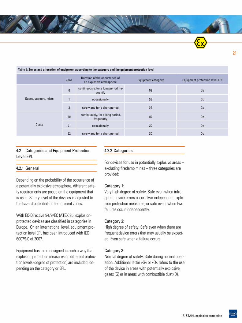
Table 8: Zones and allocation of equipment according to the category and the quipment protection level
ZoneDuration of the occurrence of
an explosive atmosphereEquipment category Equipment protection level EPL
Gases, vapours, mists
0continuously, for a long period fre-
quently1G Ga
1 occasionally 2G Gb
2 rarely and for a short period 3G Gc
Dusts
20continuously, for a long period,
frequently1D Da
21 occasionally 2D Db
22 rarely and for a short period 3D Dc
21
R. STAHL explosion protection
Devices for use in firedamp mines are classified in two categories:
Category M1: Very high degree of safety. Safe even when infre-quent device errors occur. Devices may still be op-erated when a potentially explosive atmosphere occurs.
Category M2: High degree of safety. Safe during normal opera-tion, even under difficult operating conditions. Devices must be turned off in case of potentially explosive atmosphere.
4.2.3 Equipment protection level EPL
Pursuant to IEC 60079-0 (2007), devices for poten-tially explosive areas are classified into three pro-tection levels (for devices used in firedamp mines two protection levels are determined):
EPL Ga or Da: Devices with a »very high« protection level for use in hazardous areas where there is no ignition haz-ard during normal operation and in case of fore-seeable or infrequent faults/malfunctions.
EPL Gb or Db: Devices with a »high« protection level for use in hazardous areas where there is no ignition hazard during normal operation or in case of foreseeable faults/malfunctions.
EPL Gc or Dc: Devices with »extended« protection level for use in hazardous areas where there is no ignition hazard during normal operation and where some addition-al protective measures are applied to ensure that the usually foreseeable malfunctions of the devic-es do not cause ignition hazard.
The letters »G« and »D« determine whether the de-vice is suitable for use in areas with potentially ex-plosive gases (G) or for areas with combustible dust (D).
Devices for firedamp mines:
EPL Ma: Device with a »very high« protection level for mounting in firedamp mines, which ensures the re-quired degree of safety so that no ignition hazard occurs during normal operation, or in case of fore-seeable or infrequent faults/malfunctions, even if the device is still in operation during a gas leak.
EPL Mb: Device with a »high« protection level for mounting in firedamp mines, which ensures the required de-gree of safety so that there will be no ignition haz-ard during normal operation or in case of foreseea-ble faults/malfunctions, during the period between gas leak and turning-off of the device.
Range of application of equipment of a certain cat-egory or EPL in the respective danger zones in po-tentially explosive areas is shown in table 7.
22
GrundlagenExplosion protection
4. technical principles

R. STAHL explosion protection
4.3 Groups
4.3.1 General
Equipment Groups according to EuropeanDirective 94/9/EC (ATEX 95)
The ATEX-Directive classifies the equipment for use in potentially explosive Atmospheres in two groups:
Equipment group I:Equipment intended for use in underground parts of mines, and in those parts of surface installa-tions of such mines, liable to be endangered by firedamp and/or combustible dust.
Equipment group II:Equipment intended for use in other places liable to be endangered by explosive atmospheres.
Up until now explosion-protected equipment has been divided in two groups:
Groups according to IEC 60079-0
Group I:Equipment for use in mines susceptible tofiredamp.
Group II:Equipment for use in places with an explosive gas atmosphere other than mines susceptible to fire-damp..
Electrical devices for mines, where, in addition to firedamp, proportions of gases other than methane may occur, have to fulfil the requirements for group II as well as those for group I.
Devices of group II are further divided, depending on their intended field of application, into devices for areas that are hazardous because of gases, va-pours or mists and those for areas that are hazard-ous because of dust.
With the publication of IEC 60079-0 in 2007 group III for potentially explosive areas due to dust was introduced. Group II is reserved for equipment for use in areas with explosive gases.
Group II: Devices for areas with explosive gases, excluding mines.Group III:Devices for areas with combustible dusts, exclud-ing mines.
Electrical devices of group II (gas) are divided in group IIA, IIB and IIC, depending on the properties of the potentially explosive area they are intended for (see table on page 9). This classification con-cerns types of protection Flameproof Enclosure and Intrinsic Safety. For type of protection Flameproof Enclosure it is based on the maximum experimental safe gap (MESG) which is a measure for the dis-charge behaviour of a hot flame through a narrow gap, and for Intrinsic Safety it is based on the mini-mum ignition current (MIC), which is a measure for the minimum ignition energy of the gases and va-pours that occur.
Table 9: Subdivision of group II
Explosion group typical gasmaximum experi-mental safe gap
Minimum ignition current ratio*
IIA Propan > 0,9 > 0,8
IIB Ethylen 0,5 … 09 0,45 ... 0,8
IIC Wasserstoff < 0,5 < 0,45
* rel. to methane = 1
23

R. STAHL explosion protection
Devices for areas with combustible dust (group III) are subdivided in groups IIIA, IIIB and IIIC, depend-ing on the type of dust:IIIA: combustible flyingsIIIB: non-conductive dustIIIC: conductive dust
4.3.2 Classification
The substances and thus the explosive areas in which those substances occur are classified in groups according to these criteria. The devices that are used have to be designed to fulfil the require-ments of the group, which increase from IIA to IIC and from IIIA to IIIC. A device that fulfils the crite-ria for IIC can be used in areas that are classified as IIC, IIB and IIA, devices that fulfil the criteria for IIB can be used in areas IIB and IIA, while devices for IIA may only be used in area IIA. Devices for groups IIIA, IIIB and IIIC can be handled likewise.
4.4 Ignition temperature and temperature classes
4.4.1 General
Ignition temperature of a combustible gas, vapour or dust is the lowest temperature of a heated sur-face, which may ignite the gas/air or vapour/air mixture. It is virtually the lowest temperature at which a hot surface may ignite the respective ex-plosive atmosphere.
4.4.2 Explosive gases
Combustible gases and vapours are classified in temperature classes according to their ease of igni-tion (see table 10). Maximum surface temperature of an electrical device always has to be lower than the ignition temperature of the gas or vapour/air mixture in which it is used. Of course, equipment that complies with a higher temperature class (e.g. T5) is also permissible for applications for which a lower temperature class is required (e.g. T2 or T3). In North America a system with further division in sub-temperature classes exists.
Table 10: Temperature Classes
Ignition temperature of gases and vapors in °C
Temperature class Maximum Surface tempera-ture on the equipment in °C
> 450 T1 450
> 300 up to 450 T2 300
> 200 up to 300 T3 200
> 135 up to 200 T4 135
> 100 up to 135 T5 100
> 85 up to 100 T6 85
24
GrundlagenGrundlagenExplosion protection
4. technical principles

R. STAHL explosion protection
4.4.3 Combustible dusts
Combustible dusts are not classified in tempera-ture classes. Minimum ignition temperature of a dust cloud has to be compared to the maximum surface temperature of the equipment. A safety factor has to be allowed for. The maximum sur-face temperature of the equipment must not ex-ceed 2/3 of the minimum ignition temperature of the dust cloud. As dusts may also deposit on the equipment, the minimum ignition temperature of the dust deposit also has to be considered (smoul-dering temperature). The smouldering temperature is the lowest temperature of a hot surface at which a 5 mm dust layer may ignite. Comparison to the maximum surface temperature of the equip-ment has to be done with a safety factor of 75 K. Thermal insulation increases with higher layers.
The dust layer may ignite with lower temperatures. That is why a reduced surface temperature on the equipment is permissible.
It is determined according to the diagram shown in picture 4 (EN 60079-14). If the layer is more than 50 mm thick the smouldering temperature has to be determined through a laboratory test. This also applies to a layer thickness of more than 5 mm when the smouldering temperature at a lay-er thickness of 5 mm is lower than 250 °C. Labora-tory tests are also required when the equipment is completely covered with combustible dust.
4.5 Types of protection
In areas in which an explosive atmosphere may still be expected despite the implementation of preven-tative measures, only explosion-protected equip-ment may be used. Electrical explosion-protected equipment for use in areas with explosive gases can be designed in different types of protection, pursuant to the construction regulations of stand-ard series IEC 60079. If electrical equipment is meant to be used in areas with combustible dust, standard series IEC 61241 has to be applied.
Types of protection for non-electrical equipment are stipulated in standard series EN 13463. The type of protection a manufacturer employs for a certain device mainly depends on the type and
Ignitiontemperature of a5 mm thick layer
Thickness of layer [mm]
Max
. per
mis
sibl
e su
rface
tem
pera
ture
[°C]
100
200
300
10 20 30 40 50
≥ 400 ° C
≥ 320 ° C
≥ 250 ° C
Fig. 4: Determination of the max. Surface Temperature of Dust Layers of 5 mm to 50 mm
25

R. STAHL explosion protection
corresponds to category 2 or EPL Gb which is suita-ble for Zone 1. With regards to safety all standard-ized types of protection within a category or an equipment protection level can be considered as being equal.Tables 11 – 15 show an overview of the standard-ized types of protection and describe the basic prin-ciple and the customary fields of application.
function of the device. For some types of protec-tion there are several protection levels. These cor-respond to the equipment categories pursuant to Directive 94/94/EC, or to the equipment protection levels EPL according to IEC 60079-10 published in 2007. Therefore, there is design Ex ia for Intrinsic Safety, which is classified as being category 1 or EPL Ga. It can be installed in Zone 0. Design Ex ib
Table 11: Types of Protection for Electrical Apparatus in Explosive Gas Atmosphere, Part 1
Type of protection in accor-dance in IEC, EN, ISAand NFPA
Presentation(diagram)
Basic principle Main application
Increased safety »e«EN 60079-7 ISA 60079-7IEC 60079-7
Here additional measures are applied to increase the level of safety, thus preventing the possibility of inad-missibly high temperatures and the occurrence of sparks or electric arcs within the enclosure or on ex-posed parts of electrical equipment, where such igni-tion sources would not occur in normal service.
Terminal and connection boxes, control boxes for installing Ex-components (which have a different type of protection), squirrel cage motors, light fittings
Flameproof enclosure »d«EN 60079-1 ISA 60079-1IEC 60079-1
Parts which can ignite a potentially explosive atmo-sphere are surrounded by an enclosure which with-stands the pressure of an explosive mixture exploding inside the enclosure and prevents the transmission of the explosion to the atmosphere surroundingthe enclosure.
Switchgear and control gear, display units, control systems, motors, transformers, heating equipment, light fittings
Pressurized enclosure »p«EN 60079-2 NFPA 496IEC 60079-2
The formation of a potentially explosive atmosphere in-side an enclosure is prevented by maintaining apositive internal pressure of protective gas in relation to the surrounding atmosphere and, where necessary, by supplying the inside of the enclosure with a constant flow of protective gas which dilutes any com¬bustible mixtures.
Switching and control cabinets, analysers, large motorspx = use in Zone 1, 2 py = use in Zone 1, 2pz = use in Zone 2
Intrinsic Safety »i«EN 60079-11 ISA 60079-11IEC 60079-11
Equipment that is used in a potentially explosive area only con¬tains intrinsically safe electric circuits. An electric circuit is intrinsically safe if any spark or ther-mal effect produced under specified test conditions (which include normal operation and specifiied fault conditions) is not capable of causing ignition of a given explosive atmosphere.
Measurement and control technology, field bus technology, sensors, actuators
ia = use in Zone 0, 1, 2ib = use in Zone 1, 2ic = use in Zone 2[Ex ib] = associated electrical apparatus —installation in the safe area
EN 60079-25IEC 60079-25
Intrinsic Safety evaluation for defined systems (equip-ment and cables)
Intrinsically safe systems
EN 60079-27 ISA 60079-27IEC 60079-27
FISCO Ex ia IIC T4 Definition of the physical and electrical limit values of the intrinsically safe bus string
Intrinsically safe field bus systems (FISCO) for Zone 1
26
GrundlagenGrundlagenExplosion protection
4. technical principles

R. STAHL explosion protection
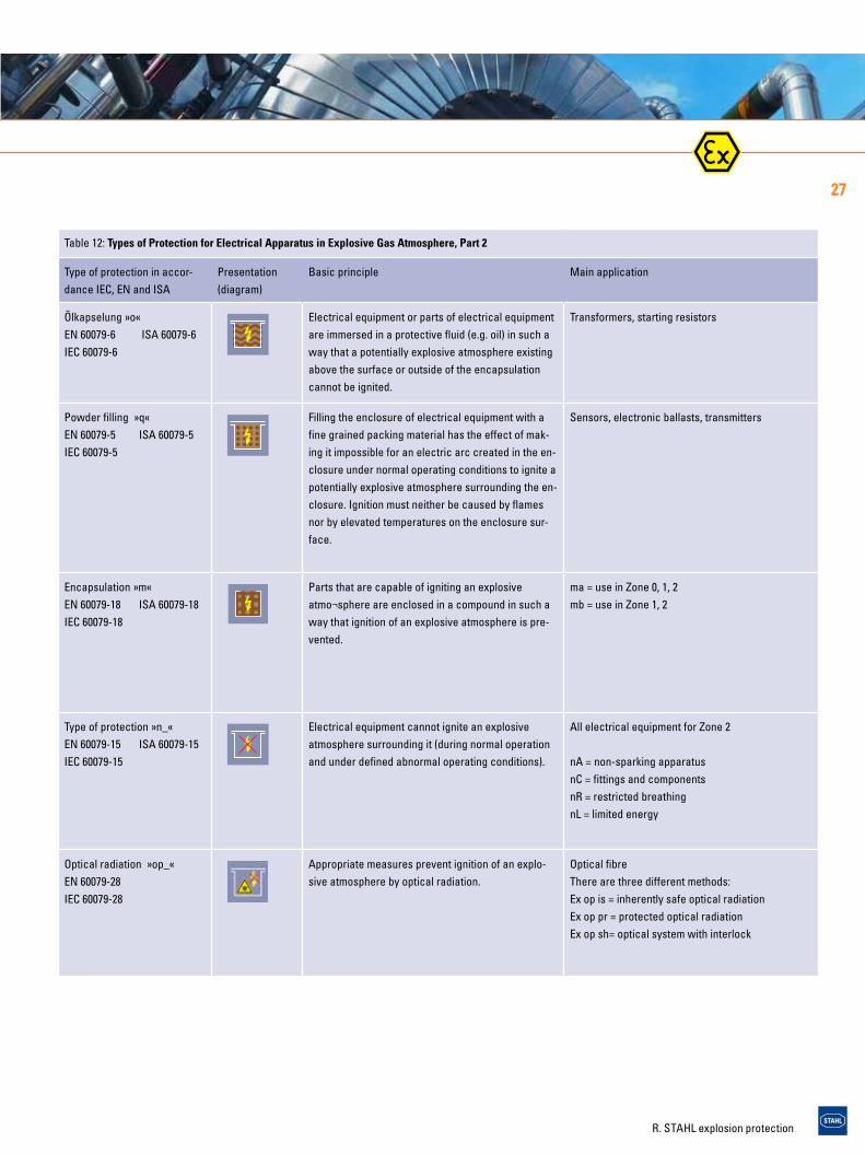
Table 12: Types of Protection for Electrical Apparatus in Explosive Gas Atmosphere, Part 2
Type of protection in accor-dance IEC, EN and ISA
Presentation(diagram)
Basic principle Main application
Ölkapselung »o«EN 60079-6 ISA 60079-6IEC 60079-6
Electrical equipment or parts of electrical equipment are immersed in a protective fluid (e.g. oil) in such a way that a potentially explosive atmosphere existing above the surface or outside of the encapsulation cannot be ignited.
Transformers, starting resistors
Powder filling »q« EN 60079-5 ISA 60079-5IEC 60079-5
Filling the enclosure of electrical equipment with a fine grained packing material has the effect of mak-ing it impossible for an electric arc created in the en-closure under normal operating conditions to ignite a potentially explosive atmosphere surrounding the en-closure. Ignition must neither be caused by flames nor by elevated temperatures on the enclosure sur-face.
Sensors, electronic ballasts, transmitters
Encapsulation »m«EN 60079-18 ISA 60079-18IEC 60079-18
Parts that are capable of igniting an explosive atmo¬sphere are enclosed in a compound in such a way that ignition of an explosive atmosphere is pre-vented.
ma = use in Zone 0, 1, 2mb = use in Zone 1, 2
Type of protection »n_«EN 60079-15 ISA 60079-15IEC 60079-15
Electrical equipment cannot ignite an explosiveatmosphere surrounding it (during normal operation and under defined abnormal operating conditions).
All electrical equipment for Zone 2
nA = non-sparking apparatusnC = fittings and componentsnR = restricted breathingnL = limited energy
Optical radiation »op_«EN 60079-28IEC 60079-28
Appropriate measures prevent ignition of an explo-sive atmosphere by optical radiation.
Optical fibreThere are three different methods:Ex op is = inherently safe optical radiation Ex op pr = protected optical radiationEx op sh= optical system with interlock
27
R. STAHL explosion protection
Table 13: Electrical Apparatus for Use in the Presence of Combustible Dust
Type of protection in accor-dance in IEC, EN and ISA
Presentation(Diagram)
Basic principle Main application
Protection by enclosure »t«IEC 60079-31EN 60079-31
IEC 61241-1EN 61241-1ISA 61241-1
Tightness of the enclosure prevents ingress of dust or limits it to a nonhazardous amount. So ignitable equipment can be fitted into the enclosure. The surface temperature of the enclosure must not ignite the surrounding atmosphere.
Switchgear and control gear, connection and terminal boxes, motors, light fittings
Pressurized enclosure »p«IEC 61241-4EN 61241-4ISA 61241-2
The formation of a potentially explosive atmosphere inside an enclosure is prevented by maintaining a positive internal pressure of protective gas in relation to the surrounding at-mosphere and, where necessary, by sup¬plying the inside of the enclosure with a constant flow of protective gas which dilutes any combustible mixtures.
Switching and control cabinets, motors
Intrinsic Safety »i«IEC 60079-11EN 60079-11
IEC 61241-11EN 61241-11ISA 61241-11
Equipment that is used in a potentially explosive area only contains intrinsically safe electric circuits. An electric cir-cuit is intrinsically safe if any spark or thermal effect pro-duced under specified test conditions (which include normal operation and specified fault conditions) is not capable of causing ignition of a given explosive atmo¬sphere.
Measurement and control technology, field-bus technology, sensors, actuators
[Ex ibD] = associated electrical apparatus — installation in the safe area
Encapsulation »m«EN 60079-18IEC 60079-18
IEC 61241-18EN 61241-18ISA 61241-18
Parts that are capable of igniting an explosive atmo¬sphere are enclosed in a compound in such a way that ignition of an explosive atmosphere is prevented.
Display units, sensors
Type of ignition protection for areas with combustible dust are integrated into the series of standards 60079. The symbols for these ty-pes of ignition protection are simplified in standard IEC 60079-0 (Table 14).
Tabelle 14: Kennzeichnung nach Normenreihen IEC 61241 und IEC 60079
Normenreihe 61241 Normenreihe 60079 Einsatzbereich
Norm Symbol Norm Symbol Zone
Schutz durch Gehäuse
IEC 61241-1
tDA20, tDB20tDA21, tDB21tDA22, tDB22
IEC 60079-31
ta 20
tb 21
tc 22
Überdruckkapselung
IEC 61241-4pD21pD22
IEC 60079-2pb 21
pc 22
28
GrundlagenExplosion protection
4. technical principles

R. STAHL explosion protection
Table 15: Types of Protection for Non-electrical Apparatus used in Explosive Gas Atmosphere and in the Presence of Combustible Dust
Type of protection in accor-dance in IEC or EN
Presentation(Diagram)
Basic principle Main application
Constructional safety »c«EN 13463-5
Proven technical principles are applied to equipment types which do not have any ignition source under normal operating condi-tions, so that the risk of mechanical failures which may cause ig-nitable temperatures and sparks is reduced to a minimum
Couplings, pumps, gear drives, chain drives, belt conveyors
Flameproof enclosure »d« EN 13463-3
Parts which can ignite a potentially explosive atmo-sphere are surrounded by an enclosure that with-stands the pressure of an explosive mixture exploding inside the enclosure and prevents the transmission of the explosion to the atmosphere surrounding the enclosure.
Brakes, couplings
Pressurized enclosure »p«EN 600079-2
The formation of a potentially explosive atmosphere inside an en-closure is prevented by maintaining a positive internal pressure of protective gas in relation to the surrounding atmosphere and, where necessary, by supplying the inside of the enclosure with a constant flow of protective gas which dilutes any combustible mixtures.
Pumps
Control of ignition source »b«EN 13463-6
Sensors are integrated in the equipment to detect emerging haz-ardous conditions and to take countermeasures at an early stage, before potential ignition sources become effective. The applied measures can be initiated automatically by means of a direct con-nection between the sensors and the ignition protection system or manually by issuing a warning message to the operator of the equipment.
Pumps, belt conveyors
Liquid immersion »k«EN 13463-8
Ignition sources are rendered inactive by immersion in a protec-tive liquid or by constant moistening using a liquid film.
Submersible pumps, gears,liquid immersion
Flow restricting enclosure »fr«EN 13463-2
The effective sealing of an enclosure can reduce ingress of ex-plosive atmosphere to such an extent that no potentially explosive atmosphere can form inside. Pressure differences between the internal and the external atmo¬sphere because of change in tem-perature have to be taken into account. Application is limited to equipment category 3.
Equipment exclusively for Zone 2 or Zone 22
29Intrinsic safety
IEC 61241-11iaD20iBD21
IEC60079-11ia 20
ib 21
Encapsulation
IEC 61241-18maD20maD21
IEC 60079-18
ma 20
mb 21
mc 22

R. STAHL explosion protection
4.5.1 Applications of Type of Protection»Intrinsic Safety«
The type of protection »Intrinsic Safety« is basedon the principle of energy limitation within anelectric circuit. The energy from a power circuitcapable of causing an explosive atmosphere toignite is thus limited to such an extent that thesurrounding explosive atmosphere cannot igniteas a result of sparks or inadmissible surface heat-ing of the electrical components.
The type of protection »Intrinsic Safety« is particu-larly used in measurement and control technology,as no high currents, voltage and power are re-quired here.
Terms and Definitions
Intrinsically safe electrical circuitAn electric circuit in which neither a spark northe effect of heat can cause a defined explosiveatmosphere to ignite.
Intrinsically safe apparatusElectrical apparatus in which all circuits areintrinsically safe.
Associated apparatusElectrical apparatus which contains circuits, someof which are intrinsically safe and some are not,and which is constructed such that the non-intrinsi-cally safe circuits cannot adverselyaffect the intrinsically safe circuits (table 16).An essential aspect of the type of protection»Intrinsic Safety« is reliability with regard to theobservance of voltage and current limit values,even if determined faults may occur. Intrinsicallysafe apparatus and intrinsically safe componentsfrom related equipment are classified in differentlevels of protection »ia«, »ib« or »ic« with regardto infallibility. The various protection levels are at-tuned to the different zones. Intrinsic safety »ia« is suitable for use in Zone 0, protection level »i« for use in Zone 1 and protection level »ic« is suitable for use in Zone 2.
Table 16: Difference between intrinsically safe and associated apparatus
Intrinsically safe apparatus Associated apparatus
These contain intrinsically safe circuits only. These contain both intrinsically safe and non-intrinsically safe electric circuits.
Ex ib IIC T6 [Ex] ib IIC T6 Ex de [ib] IIC T6
All necessary information such as category, explosion group and temperature class is provided.
The square brackets indicate that the associated electrical apparatus contains an intrinsically safe electric,circuit that may be introduced into Zone 1, gas groups IIA, IIB and IIC.
The apparatus may be used in Zone 1 The apparatus has to be installed outside of the potentially explosive area.
Thanks to being integrated in a flameproof enclosure »d«, the apparatus may be used in Zone 1.
30
GrundlagenExplosion protection
4. technical principles

R. STAHL explosion protection
31
Fig. 6: Electric Isolators IS pac
Isolation of Intrinsically Safe Circuits fromAn important measure for intrinsically safe circuitsis the safe isolation of all intrinsically safecircuits from non intrinsically safe circuits (fig. 6).Safe electrical isolation is always required, withthe exception of safety barriers.
Electric isolation is generally recommended forZone 0. Zener diodes, used for limiting voltage,as well as other semiconductor components areconsidered to be fallible and must therefore besafeguarded by means of redundant components.Wire wound or sheet resistors for current limita-tion are considered to be infallible components(they have high resistivity in the event of a fault).Therefore one single component is sufficient.
Single fault safetyIf one safety-relevant component fails, a second component has to perform the task (protection lev-el »ib«: a redundant component).
Double fault safetyIf safety-relevant components fail, a third compo-nent has to perform their task (level of protection »ia«: two redundant zener diodes).
Zone 2 and Division 2Intrinsic safety »ic« - energy-limited circuits »nL« - non incendive »NI«In the USA the principle of energy limitation is treated differently, depending on the field of appli-cation. The demands on devices for Class I Zone 2 correspond to a large extent to the IEC-require-ments. Intrinsic safety type ic will replace the ener-gy-limited circuits type nL, as stipulated in the IEC-standards. For Class I Division 2, energy limitation will be implemented as >non-incendive< (NI) cir-cuits. The difference of the various methods is shown in tables 17 and 18.

R. STAHL explosion protection
4.5.2 Applications of Type of Protection »c«
Non-electrical apparatus are often realised with the type of protection “Constructional safety”. The risk of failure, which may cause ignition sources inan apparatus, is reduced to a low level by meansof constructional measures for this type of protec-tion. To do so, for example, for hot surfaces, me-chanically
Table 18: Installation and maintencance
Ex ic Ex nL NI
Cabel IEC 60079-14 US-standard
Marking Yes.If colored, blue
No requirements No requirements
Isolation to non-Ex i/nL Circuits 50 mm No (50 mm to I.S.) Separation
Clearance to blank conducting mate-rial
to non-Ex i: 50 mm;to separate Ex i: 6mm;to earth: 3mm
No special requirements Separation
Verification of intrinsic safe circuits Yes Yes Yes
Operational maintenance *) Yes Yes Yes
Corrective maintenance *) Yes Yes No
*) NEC 500 differentiates between servicing and repair. For example, during repair the replacement of defective non-incendice components is not allowed.
32
Table 17: Standards
Ex ic Ex nL NI
Description Intrinsic safety Energy limited „Non incendive“
Classification area (gas) Zone 2 Zone 2 Class I Div. 2
Classification area (dust) Zone 22 (Ex icD) Zone 22 (Ex nL) Class II + III Div. 2
Standard IEC 60079-11 IEC 60079-15 NEC500
Fieldbus IEC 60079-27-FISCO IEC 60079-27-FNICO --
Maintenance IEC 60079-17 IEC 60079-17 ANSI/ISA 12.12.01
Note: Ex nL will be replaced by Ex ic.
generated sparks, and electrostatic discharges areexamined. The measures depend mainly on theequipment type and may vary significantly. Here,the examined material combination, dimensioning,tolerances, and lubricants of moving parts playa role. Even servicing intervals and monitoring ofthe service life may be of vital importance.The manufacturer defines the intended use in theoperating instructions. By doing so, ambient and
GrundlagenExplosion protection
4. technical principles

R. STAHL explosion protection
operating conditions, as well as the admittedoperating parameters are specified. The operatorhas to observe the operating instructions.
4.5.3 Application and Combination ofTypes of Protection »d« and »e«
The most important type of protection for switch-gear is »Flameproof Enclosures«, usually inconjunction with »Increased Safety«. Switchgeardoes produce sources of ignition in normal use andtherefore »Increased Safety« alone is not applica-ble as type of protection for switchgear, since»Increased Safety« is based on the principle ofavoiding sources of ignition through additional measures.However, »Increased Safety«, in conjunction with»Flameproof Enclosures«, cut a fine figure for
33
Ex e Ex eEx em
Ex eEx e
Ex em
Ex ed
Ex d
Ex ed
Ex ed
Fig. 5: Combination of Types of Protection Emergency Light Fitting C-Lux 6108
switchgear and control gear. Modern, explosionprotected luminaires also use a combinationof several types of protection to achieve the bestresults with regard to safety, function, and econmy (fig. 5).

R. STAHL explosion protection
4.6 Marking
IECMarking of electric devices is defined in IEC 60079-0 issued in 2004 for explosive gas atmos-pheres and in IEC 61241-0 issued in 2004 for areas with combustible dusts. In addition to the manu-facturer’s name or trade mark, type designation, serial number, and the test centre with certificate number, a special coding is required that describes the intended use of the device:> Ex-symbol > Symbol of every type of protection that has
been applied The associated electrical devices that are
meant to be installed in the hazardous areas, have to be marked with the symbols for the type of protection in squared brackets, e.g. Ex d[ia] IIC T4.
> Group II, IIA, IIB or IIC for potentially explosive gas atmospheres
> Temperature class for areas with potentially ex-plosive gas atmospheres or max. surface tem-perature in °C for areas in which combustible dusts may be present.
Examples: Ex d e IIC T4 Ex d [ia] IIB T5 Ex mbD T120°C
The types of protection have to clearly show which level they achieve. Some types of protection al-ready contain the appropriate symbol (e.g. ia):With others the letter a, b or c has to be added d -> dbExample: Ex db eb IIC T4 Ex db [ia] IIB T5The second variant (called alternate marking in the standard) is preferentially used.
With this standard, groups for areas where poten-tially explosive dusts may be present have been in-troduced as well:
IIIA: combustible flyingsIIIB: non-conductive dustIIIC: conductive dust Example for marking of dust: Ex tb IIIB T120°C
Europe
In Europe, in addition to the marking according to the standard the requirements pursuant to EC-Di-rective 94/9/EC (ATEX 95) have to be met as well:
> Manufacturer’s address > Symbol and the identification number of
the notified body > and category 1, 2 or 3, as well as group II and
the letter G (gases) or D (dust) Example: 2 II G Previously, »Ex« was replaced by »EEx« in Europe, if the marking was done pursuant to the standard. Reference has thus been made to the European Standards (EN 50014 ff), which differed from the IEC-standards at that time. With the current edi-tions of the standards this is no longer required, thus devices in Euope are only marked »Ex« now as well.
Up until now standards for non-electrical devices have only been developed by CEN in Europe. Such standards do not yet exist on an international level.Marking closely follows the marking of electrical devices.Exceptions:> Ex is not stated, as with ATEX the -sign al-
ready refers to explosion protection
34
GrundlagenExplosion protection
4. technical principles

R. STAHL explosion protection
35
> Ignition protection level is not given. Alternative marking is not used either. The equipment pro-tection level has to be defined with the
category.
A summary of the topic marking of electrical and non-electrical devices can be found in the enclo-sure 7.7 and 7.8.
North America
In addition to such data as for example, manufac-turer, type, serial number and electrical data, data concerning explosion protection must be included in the marking of the equipment. Specifications are given in NEC, CEC and the respective construc-tion regulations of the test centres.
Class I, II & III, Division 1 and 2Approved electrical equipment for Class I, Class II and Class III, Division 1 and Division 2 has to be marked with the following data:1. Class(es), Division(s) (optional, except for Division 2) 2. Gas-/dust-group(s) 3. Operating temperature or temperature class (optional for T5 and T6) Example: Class I Division 1 Groups C D T4
Class I, Zone 0, 1 and 2For equipment for use in Class I, Zone 0, Zone 1 or Zone 2 a difference is made between »Division Equipment« and »Zone Equipment«.
(1) Division EquipmentEquipment approved for Class I, Division 1 and/or Class I, Division 2 may be marked with the follow-ing data:1. Class I, Zone 1 or Class I, Zone 2 2. Gas group(s) IIA, IIB or IIC 3. Temperature class4. Types of protection Example: Class I Zone 1 d,e IIC T4 (2) Zone EquipmentEquipment complying with several types of protec-tion pursuant to Article 505 of NEC and section 18 of CEC have to be marked as follows:1. Class (optional in Canada) 2. Zone (optional in Canada) 3. Symbol AEx (USA) or Ex or EEx (Canada) 4. Symbol of the type(s) of protection that have been applied5. Group of the electrical equipment II or gas group(s) IIA, IIB or IIC 6. Temperature class Example: Class I Zone 0 AEx ia IIC T6
Russia
Marking of explosion-protected electrical equip-ment is done according to GOST R 51330.0-99 and according to the standards for the individual types of protection.Marking of explosion protection contains:> the level of explosion protection> Ex-symbol > symbol of the types of protections that have
been applied > equipment group (I, II or IIA, IIB, IIC) > temperature class symbol X, when special conditions have to be
observed for safe use or if the product is an Ex-component.

R. STAHL explosion protection
36
GrundlagenExplosion protection
5. installation and operation of electrical equipment
The installer must observe the installationrequirements, and select and install the electricapparatus correctly for its intended use.Manufacturers of explosion protected apparatusare responsible for routine testing, certificationand documentation and are required to ensure thateach device manufactured complies with theapproved design.
5. Installation and Operation of ElectricalEquipment in Hazardous Areas
5.1 Duties of Installer, Manufacturerand Employer
Safety in potentially explosive areas can only beguaranteed by a close and effective workingrelationship amongst all parties involved (fig. 7).The employer is responsible for the safety of hisinstallations. It is his duty to verify where thereis a risk of explosion and then divide areas intoZones accordingly. He must ensure that the instal-lation is installed in accordance with regulationsand that it is inspected before initial use. The in-stallation must be kept in a regular and correct state through periodic inspection and maintenance.
The requirements for the operation of facilities in hazardous areas are defined in national regula-tions. In Europe the minimum regulations are stipu-lated in Directive 99/92/EC (ATEX 137). In Germany the Health and Safety at Work Regulations (BetrSi-chV) must be maintained. They are specifically de-fined with the different TRBS (technical rules for operational safety) – please also see table 5 on page 14. On an international level and on the Euro-pean level, different standards have been estab-lished which can be used as sources of information in Germany (see table 19). However, this only ap-plies if it does not contradict the German Health and Safety at Work Regulations or a TRBS.
Fig. 7: Co-operation of all parties involved
Employer
Manufacturer
Installer
Standardization
Authority
Testing authority
Table 19: Explosive atmospheres (gas and combustible dust)
IEC EN
Electrical installations design, selection and erection IEC 60079-14 EN 60079-14
Electrical installations inspection and maintenance IEC 60079-17 EN 60079-17
Equipment repair, overhaul and reclamation IEC 60079-19 EN 60079-19

R. STAHL explosion protection
37
5.2 Classification of Zones and Selection of Apparatus
The question of possible risks of explosion mustbe addressed at the early stages new facilityplanning. When classifying potentially explosiveareas, the influence of natural or technicalventilation must be considered in addition to thequantity of flammable substances being released.Furthermore, the explosion safety characteristicsmust be ascertained for the flammable substances being used (see Appendix 7.2). Only then can a de-cision be reached on the classification of potential-ly explosive areas into Zones and the selection of suitable apparatus.Equipment shall only be used within the ambienttemperature range stipulated in its marking.
If the marking does not contain any information,the standard range of between –20 °C and +40 °Capplies.Electrical apparatus with the types of protection»d« and »i« must correspond to an explosion groupIIA, IIB or IIC. Electrical apparatus must be selectedand installed such that it is protected againstexternal influences which may adversely affect theexplosion protection measures.
5.3 Methods of Installation
Essentially, three systems are used for electricalinstallations in hazardous areas:
> 1. Cable system with indirect entry> 2. Cable system with direct entry> 3. Conduit system
The technical design of the electrical apparatusused with the individual types of installation is ac-cordingly different.
Only the conduit system or mineral insulatedcables (MI) are permitted in the USA for all appli-cations in Class 1, Division 1 in accordance withNEC 501-4, whereby the mineral insulated cablesare mainly used as heating lines and fire resistantsignal and control lines. Certain types of cableand line are also permitted in Division 2. A com-parison of the various systems is shown below.
Cable systemsCable systems are mainly used in Europe. For this,high-quality cables are laid uncovered. It is onlyin areas in which mechanical damage couldbe expected that they are laid in conduits that areopen at both ends.

R. STAHL explosion protection
38
GrundlagenExplosion protection
5. installation and operation of electrical equipment
Fig. 8: Methods of Installation worldwide: Left: Cable sys-tem with indirect entry; Cen-tre: Cable system with direct entry; Right: Conduit system
In the case of indirect entry, the cables and linesare conducted via cable glands into a connectionchamber in the type of protection “IncreasedSafety” and connected to the terminals also pro-vided in “Increased Safety”. From here, the individual wires are conducted via flameproofbushings into the flameproof enclosure.The cable bushings are installed by the manufac-turer, with the result that, by contrast withdirect entry, a routine test of the factory wiredflameproof enclosure can be made.The installation engineer need only open theconnection chamber for the connection, not theflameproof enclosure.
In the case of direct entry, the connectingcables are entered directly into the flameproofenclosure. Only cable glands that have beenspecially certified for this purpose may be usedfor this type of entry.
The flexible gasket and the cable sheath mustform a flameproof joint through which no flamescan penetrate. For this reason, attention mustbe paid to the appropriate selection of cable glanddepending on both the type and structure ofcable and installation location. If the flameproofenclosure has to be used in a IIC atmosphereor if a flameproof enclosure with a volume biggerthan 2 dm³ has to be applied in Zone 1, the gasketsor cable glands have to be sealed. The flameproofenclosure primarily depends here on thecare taken by the electrician when connecting thecables.

R. STAHL explosion protection
39
Before corrective maintenance, it must be ensuredthat there is no danger of explosions occurringduring this work. Normally, formal written permis-sion for this should be acquired from thecompany management. On completion of the work,documentation should be kept of what workwas carried out, and confirmation given that allrelevant regulations have been observed.
Once work is completed it should be documented what work was done and confirmed that all rele-vant regulations were adheared to.In case of overhaul which may impair explosion protection, an examination by a qualified person, acknowledged by the authorities, or an examina-tion by the manufacturer has to be done in Germa-ny (TRBS 1201 part 3).
When replacing components or complete equip-ment the technical explosion and equipment speci-fications are to be observed. This inspection may be done by an approved inspection agency.
Conduit SystemIn the case of installation using the conduit system,the electrical lines are drawn as single wiresinto enclosed metal conduits. The conduits areconnected to the housings by means of fittingsand equipped with a seal at each entrance point.The entire conduit system is flameproof. The aimof the seal is to prevent explosions which mayoccur inside the housing from transmitting intothe conduit. Otherwise, extremely high explosion pressures would be created as a result of precompression in long cylindrical tubes. For this reason, it is recom-mended that seals be installed not just at the en-trance points but at specific intervals. Drains must be installed at low points at which condensate can accumulate.
5.4 Maintenance
Periodic maintenance is required to maintain thesafety of electrical installations in hazardousareas. Personnel who carry out such maintenancework should work under the guidance of anexplosion protection expert and should be in-formed of the particular hazards involved (skilledperson, IEC 60079-17).

R. STAHL explosion protection
Table 20: Safety Ratings: Ignition Temperature, Temperature Class and Explosion Group
Material Ignition Temperature °C Temperature Class Explosion Group
1,2-Dichloroethane 440 T 2 II A
Acetaldehyde 155 T 4 II A
Acetone 535 T 1 II A
Acetylene 305 T 2 II C ³
Ammonium 630 T 1 II A
Petrol fuels 220 bis 300 T 3 II A
Benzene 555 T 1 II A
Cyclohexanone 430 T 2 II A
Diesel fuels 220 T 3 II A
Acetic acid 485 T 1 II A
Acetic anhydride 330 T 2 II A
Ethane 515 T 1 II A
Ethyl ethanoate 470 T 1 II A
Ethanol 400 T 2 II B
Ethyl chloride 510 T 1 II A
Ethylene 440 T 2 II B
Ethylene oxide 435 (self-decomposing) T 2 II B
Diethyl ether 175 T 4 II B
Ethyl glycol 235 T 3 II B
Fuel oil EL, L, M, S 220 to 300 T 3 II A
i-Amyl acetate 380 T 2 II A
Carbon monixide 605 T 1 II A
Methane 595 T 1 II A
Methanol 440 T 2 II A
Methyl chloride 625 T 1 II A
Naphtalene 540 T1 II A
n-Butanol 365 T 2 II A
n-Butanol 325 T 2 II B
n-Hexane 230 T 3 II A
n-Propyl alcohol 385 T 2 II B*
Phenol 595 T 1 II A
Propane 470 T 1 II A
Carbon disulphide 95 T 6 II C 1
Hydrogen sulphide 270 T 3 II B
Toluene 535 T 1 II A
Hydrogen 560 T 1 II C2
* The gas group for this substance has not yes been determined.1Also gas groups II B + CS2 2Also gas groups II B + H2 3Also gas groups II B + C2 H2
6.1 Safety Characteristics of Flammable Gases and Vapours
40
6. Appendix
GrundlagenExplosion protection
6. appendix

R. STAHL explosion protection
Table 21: Constructional Requirements in Europe, USA, Canada, and International Compariosn, Part 1
Type of ignition protection Abbreviation Region Installation location Standard
General requirements
AEx
Ex
Ex (EEx)
Ex
US
US
CA
EU
IEC
Class I, Division 1 & 2
Class I, Zone 0, 1 & 2
Class I, Zone 0, 1 & 2
Zone 0, 1 & 2
Zone 0, 1 & 2
FM 3600
ISA 60079-0
CSA E60079-0
EN 60079-0
IEC 60079-0
Increased safety AEx e
Ex e
Ex e (EEx e)
Ex e
US
CA
EU
IEC
Class I, Zone 1
Class I, Zone 1
Zone 1
Zone 1
ISA 60079-7
CSA E60079-7
EN 60079-7
IEC 60079-7
Non-incendive (NI)
(NI)
US
CA
Class I, Division 2
Class I, Division 2
FM 3611
C22.2 No. 213
Non-sparking apparatus AEx nA
Ex nA
Ex nA (EEx nA)
Ex nA
US
CA
EU
IEC
Class I, Zone 2
Class I, Zone 2
Zone 2
Zone 2
ISA 60079-15
CAS E60079-15
EN 60079-15
IEC 60079-15
Explosion-proof (XP)
(XP)
US
CA
Class I, Division 1
Class I, Division 1
FM 3615
C22.2 No. 30
Flameproof enclosure AEx d
Ex d
Ex d (EEx d)
Ex d
US
CA
EU
IEC
Class I, Zone 1
Class I, Zone 1
Zone 1
Zone 1
ISA 60079-1
CSA E60079-1
EN 60079-1
IEC 60079-1
Powder filling AEx q
Ex q
Ex q (EEx q)
Ex q
US
CA
EU
IEC
Class 1, Zone 1
Class I, Zone 1
Zone 1
Zone 1
ISA 60079-5
CSA E79-5
EN 50017
IEC 60079-5
Protected facilities and components AEx nC
Ex nC
Ex nC (EEx nC)
Ex nC
US
CA
EU
IEC
Class I, Zone 2
Class I, Zone 2
Zone 2
Zone 2
ISA 60079-15
CSA E60079-15
EN 60079-15
IEC 60079-15
Intrinsic Safety (IS)
(IS)
AEx ia
AEx ib
Ex ia
Ex ib
Ex ia (EEx ia)
Ex ib (EEx ib)
Ex ia
Ex ib
US
CA
US
US
CA
CA
EU
EU
IEC
IEC
Class I, Division 1
Class I, Division 1
Class I, Zone 0
Class I, Zone 1
Class I, Zone 0
Class I, Zone 1
Zone 0
Zone 1
Zone 0
Zone 1
FM 3610
C22.2 No. 157
FM 3610
FM 3610
CSA E60079-11
CSA E60079-11
EN 50020
EN 50020
IEC 60079-11
IEC 60079-11
6.2 Constructional Requirements for Explosion Protected Electrical equipment for gas atmospheres
41

R. STAHL explosion protection
Table 21: Constructional Requirements in Europe, USA, Canada and International Comparision, Part 2
Type of ignition protection Abbreviation Region Installation location Standard
Energy-limited apparatus AEx nC
Ex nL
Ex nL (EEx nL)
En nL
US
CA
EU
IEC
Class I, Zone 2,
Class I, Zone 2
Zone 2
Zone 2
ISA 60079-15
CSA E60079-15
EN 60079-15
IEC 60079-15
Pressurized enclosure Type X
Type X
Type Y
Type Y
Type Z
Type Z
AEx px
US
CA
US
CA
US
CA
US
CA
EU
IEC
US
CA
EU
IEC
US
CA
EU
IEC
Class I, Division 1
Class 1, Divison 1
Class I, Division 1
Class I, Division 1
Class 1, Division 2
Class 1, Division 2
Class I, Zone 1
Class I, Zone 1
Zone 1
Zone 1
Class I, Zone 1
Class I, Zone 1
Zone 1
Zone 1
Class I, Zone 2
Class I, Zone 2
Zone 2
Zone 2
FM 3620
NFPA 496
FM 3620
NFPA 496
FM 3620
NFPA 496
ISA 60079-2
CSA E60079-2
EN 60079-2
IEC 60079-2
ISA 60079-2
CSA E60079-2
EN 60079-2
IEC 60079-2
ISA 60079-2
CSA E60079-2
EN 60079-2
IEC 60079-2
Purged/pressurized AEx nR
Ex nR
Ex nR (EEx nR)
Ex nR
US
CA
EU
IEC
Class I, Zone 2
Class I, Zone 2
Zone 2
Zone 2
ISA 60079-15
CSA E60079-15
EN 60079-15
IEC 60079-15
Encapsulation Ex ma (EEx ma)
Ex ma
AEx m
Ex m
Ex mb (EEx mb)
Ex mb
EU
IEC
US
CA
EU
IEC
Zone 0
Zone 0
Class I, Zone 1
Class I, Zone 1
Zone 1
Zone 1
EN 60079-18
IEC 60079-18
ISA 60079-18
CSS E60079-18
EN 60079-18
IEC 60079-18
Oil immersion AEx o
Ex o
Ex o (EEx o)
Ex o
US
CA
EU
IEC
Class I, Zone 1
Class I, Zone 1
Zone 1
Zone 1
ISA 60079-6
CSA E79-6
EN 50015
IEC 60079-6
42
GrundlagenExplosion protection
6. anhang

R. STAHL explosion protection
Table 22: Degrees of Protection according to IEC 60529 – IPXX
DigitFirst digitPhysical protection
Foreign body protectionSecond digitWater protection
0 No protection No protection No protection
1Protection against back of hand contact
Protection against solid foreign bodies 50 mm Ø Protection against water drops falling vertically
2 Protection agains finger contact Protection against solid foreign bodies 12,5 mm Ø Protection against water drops falling at an angle (15°)
3 Protection against contact from tools Protection against solid foreign bodies 2,5 mm Ø Protection against water-spray at an angle up to 60°
4 Protection against contact with a wire Protection against solid foreign bodies 1,0 mm Ø Protection against water spray from all directions
5 Protection against contact with a wire Protection against dust Protection against water jets
6 Protection against contact with a wire Dust-tight Protection against strong water jets
7 Protection against intermittent immersion in water
8 Protection against continuous immersion in water
6.3 Degrees of Protection according to IEC 60529 – IPXX
Table 23: Degree of Protection provided by Enclosures according to NEMA (Publication No. 250 Enclosures for Electrical LEuqipment 1000 Volts Maximum)
Digit Degree of Protection Use
Type 1 Protection against incidental contact with the enclosed equipment. Indoor
Type 2 Protection against limited amounts of falling water and dirt. Indoor
Type 3 Protection against rain, sleet, windblown dust, and damage from external ice formation. Outdoor
Type 3R Protection against rain, sleet, and damage from external ice formation. Outdoor
Type 4 Protection against, rain, splashing water, hose directed water, and damage from external ice formation. Indoor or outdoor
Type 4X Protection against, rain, splashing water, hose directed water, and damage from external ice formation.Protection against corrosion.
Indoor or outdoor
Type 5 Protection against settling airborne dust, falling dirt, and dripping non-corrosive liquids. Indoor
Type 6 Protection against hose directed water, penetration of water during occasional temporary submersion at a li-mited depth, and damage from external ice formation.
Indoor or outdoor
Type 6P Protection against hose directed water, penetration of water during prolonged submersion at a limited depth, and damage from external ice formation.
Indoor or outdoor
Type 7 For use in locations classified as Class I, Groups A, B, C or D as defined in the NEC. Indoor
Type 8 For use in locations classified as Class I, Groups A, B, C or D as defined in the NEC. Indoor or outdoor
Type 9 For use in locations classified as Class II, Groups E, F, or G as defined in the NEC. Indoor
Type 10 Constructed to meet the applicable requirements of the Mine Safety Health Administration. Mining
Type 11 Protection against the corrosive effects of liquids and gases by oil immersion. Indoor
Type 12, 12K Protection against circulating dust, falling dirt, and dripping non-corrosive liquids. Indoor
Type 13 Protection against dust, splashing water, oil, and non-corrosive liquids. Indoor
6.4 Degrees of Protection according to NEMA Standards
43

R. STAHL explosion protection
IEC 60079 Part 0 to 31Explosive atmosphereswww.iec.de/webstore
IEC 61241 Part 0 to 18Electrical apparatus for use in the presence of combustible dustwww.iec.ch/webstore
EN 60079 Part 0 to 31Explosive atmosphereswww.cenelec.eu
EN 61241 Part 0 to 18Electrical apparatus for use in the presence of combustible dustwww.iec.ch/wekstore
EN 60529Degrees of protection provided by enclosures (IP code)www.iec.ch/webstore
EN 13463 Part 1 to 8Non-electrical equipment for potentially explosive atmospherewww.cen.eu
44
7. Literature
Directive 94/9/EU of the European Parliament andthe council of 23 March 1994 on the approximationof the laws of the member states concerningequipment and protective systems intended foruse in potentially explosive atmospheres.Official Journal of the European Communities,No. L 100/1
The Equipment and Protective Systems for Usein Potentially Explosive Atmospheres Regulations,1996 (EPS), ATEX 95/(UK).
Directive 99/92/EC on the »Minimum requirementsfor improving the health and safety protectionof the worker at risk from explosive atmospheres«16/12/1999, Official Journal of the EuropeanCommunities, L23/57–64
The Dangerous Substances and Explosive Atmos-pheres Regulations 2002, Statutory Instrument2002 No. 2776 (UK).
GrundlagenExplosion protection
7. literature
31,967 mm

R. STAHL explosion protection
II 2
G Ex
db
[ia] I
IC T
6AT
EX-m
arki
ng
haza
rdou
s pl
aces
Zone
0
Zone
20
Zone
1
Zone
21
Zone
2
Zone
22
min
es
Dang
erou
s ex
plos
ive
atm
osph
ere
cont
inou
sly
or lo
ng-
term
or f
requ
ently
likel
y to
occ
urno
t lik
ely
to o
ccur
or
for s
hort
perio
d
equi
pmen
t cat
egor
y1G
1D2G
2D3G
3DM
1 or
M2
EPL*
(IEC
/EN
600
79-0
)Ga
DaGb
DbGc
DcM
a or
Mb
equi
pmen
t-gr
oup
I: m
ines
; equ
ipm
ent-
grou
p II:
oth
er p
lace
s
min
es
Grou
p I
Met
hane
expl
osiv
e ga
s at
mos
pher
e
Grou
p II
IIAPr
opan
e
IIBEt
hyle
ne
IICHy
drog
ene
expl
osiv
e du
st a
tmos
pher
e
Grou
p III
IIIA
com
bust
ible
flyi
ngs
IIIB
non-
cond
uctiv
e du
st
IIIC
cond
uctiv
e du
st Grou
p
max
. sur
face
tem
pera
ture
expl
osiv
e ga
s at
mos
pher
e: t
empe
ratu
re c
lass
es
450
°CT1
300
°CT2
200
°CT3
135
°CT4
100
°CT5
85 °
CT6
expl
osiv
e du
st a
tmos
pher
e: s
urfa
ce te
mpe
ratu
re
T ...
°C (e
.g.:
T 80
°C)
Type
of p
rote
ctio
nst
anda
rd
sym
bol
alte
rnat
esy
mbo
lZo
neM
ain
appl
icat
ion
Stan
dard
incr
ease
d sa
fety
eeb
1te
rmin
al a
nd ju
nctio
n bo
xes,
ca
ge in
duct
ion
mot
ors,
ligh
t fitti
ngs
IEC
6007
9-7
EN 6
0079
-7
flam
epro
of e
nclo
sure
sd
db1
switc
hgea
r, co
ntro
l sta
tions
, mo-
tors
, IE
C 60
079-
1EN
600
79-1
pres
suriz
ed
encl
osur
espx py pz p
pxb
pyb
pzc
pb pc
1 1 2 21 22
switc
hgea
r and
con
trol c
abin
ets,
an
alys
ers,
larg
e m
otor
sIE
C 60
079-
2 / I
EC 6
1241
-4EN
600
79-2
/ EN
612
41-4
intri
nsic
saf
ety
ia ib ic
ia ib ic
0, 2
01,
21
2
inst
rum
enta
tion
tech
nolo
gy, fi
eld-
bus
tech
nolo
gy, s
enso
rs, a
ctua
tors
IEC
6007
9-11
/ IE
C 61
241-
11EN
600
79-1
1 / E
N 6
1241
-11
oil i
mm
ersi
ono
ob1
trans
form
ers,
sta
rting
resi
stor
sIE
C 60
079-
6EN
600
79-6
pow
der fi
lling
qqb
1se
nsor
s, e
lect
roni
c ba
llast
s, e
lec-
troni
c de
vice
s IE
C 60
079-
5EN
600
79-5
enca
psul
atio
nm
am
bm
c
ma
mb
mc
0, 2
01,
21
2, 2
2
disp
lay
units
, sen
sors
, ele
ctro
nic
devi
ces
IEC
6007
9-18
/ IE
C 61
241-
18EN
600
79-1
8 / E
N 6
1241
-18
type
of p
rote
ctio
n „n
“n_
n_c
2el
ectri
cal a
ppar
atus
for Z
one
2IE
C 60
079-
15EN
600
79-1
5
prot
ectio
n by
enc
lo-
sure
sta tb tc
ta tb tc
20 21 22
switc
hgea
r and
con
trol s
tatio
n,
term
inal
and
con
nect
ion
boxe
s,
cont
rol b
oxes
, mot
ors,
ligh
t fitti
ngs
IEC
6007
9-31
/ IE
C 61
241-
1EN
600
79-3
1 / E
N 6
1241
-1
Mar
king
of
ele
ctri
cal e
quip
men
t
* w
hen
not u
sing
the
alte
rnat
e sy
mbo
ls th
e EP
L sh
all b
e sp
ecifi
ed::
e.g.
Ex
d [ia
Ga] I
IC T
6 Gb
Type
of p
rote
ctio
n
31,967 mm
45

R. STAHL explosion protection
II 2
G c
IIC T
6AT
EX-m
arki
ng
haza
rdou
s pl
aces
Zone
0
Zone
20
Zone
1
Zone
21
Zone
2
Zone
22
min
es
Dang
erou
s ex
plos
ive
atm
osph
ere
cont
inou
sly
or lo
ng-
term
or f
requ
ently
likel
y to
occ
urno
t lik
ely
to o
ccur
or
for s
hort
perio
d
equi
pmen
t cat
egor
y1G
1D2G
2D3G
3DM
1 od
er M
2
equi
pmen
t-gro
up I:
min
es; e
quip
men
t-gro
up II
: oth
er p
lace
s
Min
es
Grou
p I
Met
hane
expl
osiv
e ga
s at
mos
pher
e
Grou
p II
IIAPr
opan
e
IIBEt
hyle
ne
IICHy
drog
ene
Grou
p
max
. sur
face
tem
pera
ture
expl
osiv
e ga
s at
mos
pher
e: t
empe
ratu
re c
lass
es
450
°CT1
300
°CT2
200
°CT3
135
°CT4
100
°CT5
85 °C
T6
expl
osiv
e du
st a
tmos
pher
e: s
urfa
ce te
mpe
ratu
re
T ...
°C (e
.g.:
T 80
°C)
Type
of p
rote
ctio
nsy
mbo
lsZo
neM
ain
appl
icat
ion
Stan
dard
cons
truct
iona
l saf
ety
c0,
1, 2
20, 2
1, 2
2co
uplin
gs, p
umps
, gea
r driv
es,
chai
n dr
ives
,bel
t driv
esEN
134
63-5
flam
epro
of e
nclo
sure
sd
1, 2
21, 2
2br
akes
, cou
plin
gsEN
134
63-3
pres
suris
atio
n p
1, 2
21, 2
2pu
mps
EN 6
0079
-2
cont
rol o
f ign
ition
sou
rces
k0,
1, 2
20, 2
1, 2
2pu
mps
, bel
d dr
ives
EN 1
3463
-8
liqui
d im
mer
sion
b0,
1, 2
20, 2
1, 2
2su
bmer
ged
pum
ps, g
ears
EN 1
3463
-6
flow
rest
rictin
g en
clos
ure
fr2 22
equi
pmen
t onl
y fo
r Zon
e 2
or
Zone
22
EN 1
3463
-2
Mar
king
of
non-
elec
trica
l eq
uipm
ent
Type
of p
rote
ctio
n
Grundlagen31,967 mm
46

R. STAHL explosion protection
31,967 mm

R. STAHL explosion protection
ID 102912S-PB-ExBasic protection-04-en-08/2011 · Printed in Germany
R. STAHL
Am Bahnhof 30, 74638 Waldenburg
Telefon +49 7942 943-0
Telefax +49 7942 943-4333
www.stahl.de