Embed Size (px)
Citation preview

No.
BEIER VARIATOR & BEIER-CYCLO VARIATOR should be handled, installed and
maintained by trained technicians.
Carefully read the maintenance manual before use.
Oil is removed from BEIER VARIATOR & BEIER-CYCLO VARIATOR before shipment.
Supply oil according to the maintenance manual before operation.
A copy of this maintenance manual should be sent to the actual user of BEIER
VARIATOR & BEIER-CYCLO VARIATOR.
This maintenance manual should be maintained by the user.
<< Notes >>
BM2001E-1
SI unit
BEIER VARIATOR® & BEIER-CYCLO VARIATOR
6000 Series
The Available Solution
POWER TRANSMISSION & CONTROLS GROUP

1
DANGER Transport, installation, plumbing, wiring, operation, maintenance, and inspections should be performed by trained
technicians; otherwise, electric shock, injury, fire, or damage to the equipment may result.
When using the equipment in conjunction with an explosion proof motor , a technician with electrical expertise
should supervise the transport, installation, plumbing, wiring, operation, maintenance and inspection of the
equipment so as to avoid a potentially hazandous, situation that may result in electrical shock, fire, explosion,
personal injury and/or damage to the equipment.
When the unit is to be used in a system for human transport, a secondary safety device should be installed to
minimize chances of accidents resulting in personal injury, death, or damage to the equipment.
When the unit is to be used for an elevator, install a safety device on the elevator side to prevent it from falling;
otherwise, personal injury, death, or damage to the equipment may result.
Safety and Other Precautions Carefully read this maintenance manual and all accompanying documents before use (installation, operation,
maintenance, inspection, etc.). Thoroughly understand the machine, information about safety, and all precautions for
correct operation. Retain this manual for future reference.
Pay close attention to the "DANGER" and "CAUTION" warnings regarding safety and proper use.
: Improper handling may result in physical damage, serious personal injury and/or
death.
: Improper handling may result in physical damage and/or personal injury.
Matters described in may lead to serious danger depending on the situation. Be sure to observe important
matters described herein.
DANGER
CAUTIONCAUTION

SpecificationsCommon
specificationsBasic type
Beier variator
Symbol
with motor
without motor
COMMON
Beier variatorwith built in gear
Beier Cyclo variator
CONTENTS
1. Inspection Upon Delivery............................................................................................................. 3
2. Storage ....................................................................................................................................... 7
3. Transport .................................................................................................................................... 7
4. Installation .................................................................................................................................. 8
5. Coupling with Other Machines ................................................................................................... 9
6. Wiring ................................................................................................................... 11
7. Operation ................................................................................................................................. 15
8. Daily Inspection and Maintenance ........................................................................................... 16
9. Lubricating Oil Cooling Device .................................................................................................. 28
10. Troubleshooting ..................................................................................................................... 30
11. Remote Control Equipment ................................................................................... 31
12. Construction Drawing................................................................................................................ 35
13. Oil seal list ............................................................................................................................... 39
14. Bearing list .............................................................................................................................. 40
15. Disk, spline list.......................................................................................................................... 42
16. Warranty ................................................................................................................................. 42
2
OP
How to Refer to the Maintenance Manual This maintenance manual is common for both Cyclo gearmotor and reducer. The symbols shown below appear in the upper
right corner of each page to indicate the classification. Read the applicable pages. On COMMON pages, these symbols
identify distinctions between gearmotors and reducers.
• Refer to the brake maintenance manual (Cat. No.MM0202E) for the handling of beier variator .
3
Beier Variator Basic type , With Built-in gear type
(1) Beier
(2) Motor
1Model name(Refer to page 5)
2Speed Rang
· Motor capacity speed
3Serial No.
Fig.1 Rating Plates of Beier Variator Basic type, or with Built-in gear type
· Motor capacity
· Motor characteristics
· Brake characteristics(optional)
3 Serial No.
4 Motor Type (Refer to page 6.)
5 Brake Type (optional)(Refer to the brake maintenance
· Motor frame size
· Motor shaft bearing No.
Fig.2 Motor Rating Plate
ER243WW
VOLTST Y P Ek W P
H zM.AMP
B.AMPB.TORQUEBRG.
SERIAL NO.
r/min
M/B INS.CLASSRATING
FRAME
N·m
JISC4004
JAPAN
I N D U C T I O N M OT O R
COMMON1. Inspection Upon Delivery
CAUTION
Unpack the unit after verifying that it is positioned right side up; otherwise, injury may result.
Verify that the unit received is in fact the one you ordered. Installing the wrong unit may result in personal injury or
equipment damage.
Do not remove the rating plate.
Verify the items listed below upon receiving the Beier Variator. If a nonconformity or problem is found, contact our nearest
agent, distributor, or sales office.
(1) Does the information on the rating plate conform to what you ordered?
(2) Was there any part broken during transport?
(3) Are all bolts and nuts tightened firmly?
1-1) How to Refer to the Rating Plate
• When making an inquiry, advice us of the model name, Serial no.
COMMON

4
M O D E LR A T I O
I N P U TO U T P U T T O R Q U E
S E R I A L N O .
B E I E R S P E E D R A N G E
R
AN9077GJ A P A N
kW r/minN-m AT MAX. SPEEDN-m AT M I N . SPEED
1Model name(Refer to page 5)
3Speed Rang
· Motor capacity speed
· Allowable outputtorque
4Serial No.
Fig.3 Rating Plates of Beier-Cyclo Variator
2Cyclo Reducer Ratio
Same as page 3.
Beier Cyclo Variator
(1) Beier Cyclo
(2) Motor
COMMON
1-2) Lubrication Method
Refer to "8-2. Confirmation of Lubrication Method" on page 17 to confirm the lubrication method.
• Oil-lubricated models are shipped without oil. Units must be filled with the proper amount of recommended oil prior
to start-up.
COMMON
COMMON

5
1-3) Type of Variator
Respective codes and motor nomenclature are shown below. Please verify that the type you received conforms to
whatyou ordered.
Nomenclature
BASIC
TYPE FRAME SIZE SUFFIX REDUCTIONRATIO
B
Shaft Direction
H Horizontal
V Vertical
Method ofMounting
H FootMount
F FlangeMount
Method of Input
Free InputShaft
M
K
P
WithMotors
WithCoupling
WithV-Pulley
BEIER
Frame Size
Suffix
BP WithBaseplate
G
GEAR
Frame Size
BEIER-CYCLO® VARIATOR
B REDUCTIONRATIO
C
V BaseMount
CYCLO®
Frame Size
B REDUCTIONRATIO
BEIERCYCLO®
Built inGear Type
BEIER
BEIER
Shaft Direction
H Horizontal
V Vertical
Method ofMounting
H FootMount
F FlangeMount
Method of Input
Free InputShaft
M
K
P
WithMotors
WithCoupling
WithV-Pulley
BEIER
Frame Size
Suffix
BP WithBaseplate
Suffix
BP WithBaseplate
BEIER
Frame SizeShaft Direction
H Horizontal
V Vertical
Method of Input
Free InputShaft
M
K
P
WithMotors
WithCoupling
WithV-Pulley
Method ofMounting
H FootMount
F FlangeMount
BEIER VARIATOR (Built in Gear Type)
BEIER VARIATOR
COMMON

6
H With Foot
Blank Flange type
1-4) Type of MotorRespective codes and motor nomenclature are shown below. Please verify that the type you received conforms to what
you ordered.
• For Cyclo with a servo motor , DC motor or Vector motor , refer to the respective motor maintenance manual.
Z T C E X
Mounting method
T Totally enclosed
Type of casing
C Ordinary cage type
K Special cage type
Rotor
V
Blank
Inverter driven (AF Motor)
Commercial power driven
Driving power
A Increased safety explosion-proof(Indoor)
Protection method
B Increased safety explosion-proof(Outdoor)
C Explosion-proof (Indoor)
CX Explosion-proof (Outdoor)
X Nonexplosion-proof (Outdoor)
Blank Indoor
E Without fan (Self-cooling)
Cooling method
F With Self-ventilating fan(External fan)
B With Separate ventilation fan
COMMON
7
COMMON
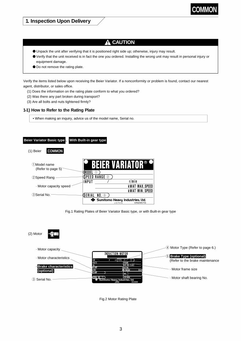
When storing Beier variators for any extended period of time, consider the following important points :
2-1) Storage Location
Store the unit in a clean, dry place indoors.
• Avoid storage outdoors or in places with humidity, dust, sudden temperature changes or corrosive gas.
2-2) Storage Period
(1) Storage period should be less than the "Rust-Proofing period" listed below.
(2) When the storage period exceeds the standard "rust-proofing period", special rust-proofing is necessary. Contact the
factory for details.
(3) Export models need export rust prevention. Contact the factory for details.
(4) Standard rust-proofing specification:
1 Outside rust-proofing
Before shipment, rust-proofing treatment is administered. Check the effect of rust-proofing, whenever necessary it
should be administered.
2 Inside rust-proofing
LubricationGrease lubricated models Oil lubricated models
Rust-proofing period 1 Year 6 Months
Storage conditionGenerally to be stored inside the shop or warehouse, relatively freeof humidity, dust, extreme temperature fluctuation, corrosive gasand similar atmosphere.
2-3) Use After Storage
(1) Oil seals will deteriorate when exposed to high temperatures and UV rays. Inspect the oil seals before operation.
Replace the oil seals after long-term storage if there is any sign of deterioration.
(2) After starting the Beier, verify that there is no abnormal sound, vibration, or heat rise. If supplied as a brakemotor,
check that the brake operates properly. If any anomaly is observed, contact our nearest agent, distributor, or sales
office.
2. Storage
3. Transport
DANGER
Do not stand directly under a unit suspended by a crane or other lifting mechanism; otherwise, injury or death may
result.
CAUTION
Exercise ample care so as not to drop the gearmotor or reducer. When a hanging bolt or hole is provided, be sure
to use it. After mounting a Beier unit to the equipment, do not hoist the entire machine using the hanging bolt or
hole; otherwise, personal injury or damage to the equipment and/or lifting device may result.
Before hoisting, refer to the rating plate, crate, outline drawing, catalog, etc. for the weight of the Beier gearmotor
or reducer. Never hoist a unit that exceeds the rating of the crane or other mechanism being used to lift it;
otherwise, personal injury or damage to the equipment and/or lifting device may result.
Table 1

8
COMMON4. Installation
DANGER
Do not use a standard unit in an explosive atmosphere (which is likely to be filled with explosive gas or steam).
Under such conditions, an explosion-proof motor should be used; otherwise, electric shock, personal injury,
explosion fire, or damage to the equipment may result.
Since the inverter itself is not explosion-proof, install an inverter-driven, explosion-proof type motor in a place
free from explosive gas; otherwise, electric shock, personal injury, explosion fire, or damage to the equipment may
result.
CAUTION Do not use the Beier variator for purposes other than those shown on the rating plate or in the manu-facturing
specifications; otherwise, electric shock, personal injury, or damage to the equipment may result.
Do not place flammable objects around the Beier variator; otherwise, fire may result.
Do not place any object around the Beier variator that will hinder ventilation. Insufficient ventilation can cause
excessive heat build-up that may result in burns or fire.
Do not step on or hang from the Beier variator; otherwise injury may result.
Do not touch the shaft end of the Beier variator, inside keyways, or the edge of the motor cooling fan with bare
hands; otherwise, injury may result.
When the unit is used in food processing applications vulnerable to oil contamination, install an oil pan or other
such device to cope with oil leakage due to breakdown or faillure; otherwise, oil leakage may damage products.
Filling lublication oil after installation.
4-1) Installation Location
Ambient temperature : -10°C to +40°C
Ambient humidity : 85% max.
Altitude : 1000m max.
Ambient atmosphere : There should be no corrosive gas, explosive gas, or steam.
The location should be well ventilated without dust.
Installation location : Indoors, with minimum dust and no water splashing.
• Units made to special specifications are necessary for installation under conditions other than the above.
• Units made according to the outdoor, explosion-proof or other specifications can be used under the specified conditions
without any problem.
• Install units where inspection, maintenance, and other such operations can be easily carried out.
• Install units on a sufficiently rigid base.
4-2) Installation Angle
Grease lubricated model Free
Oil lubricated model Low speed shaft Horizontal or Vertical (Refer to page 5. Contact us inclined installation.)
Table 2 Installation Angle
When the unit is made according to your specification for inclined installation, do not install it at any angle other than the
specified angle. (The shaft orientation of the standard outdoor variator is horizontal. Contact us for other shaft
orientations.)
• Do not remove the eyebolt on the motor. Should the eyebolt be removed, put a bolt into the threaded hole or take other
water-proofing measures to prevent water from entering the motor through the threaded hole.

9
Without motor
When the motor wiring conforms to Fig. 9 the motor shaft turns clockwise viewed from the opposite side of the load side. At that time, therotation direction of slow speed shaft is in the direction of the arrow shown below.
Type
Rotation
direction of slow
speed shaft
Viewed from
load side
Basic, Beier-Cylo (2 stages)
Rotation
direction of slow
speed shaft
Viewed from
load side
with Built-in Gear Beier Cyclo (1 stage)
· For reverse rotation, change the positions of R and T of the motor wiring.
Type Basic, Beier-Cylo (2 stages)
Rotationdirection of slow
speed shaft
A·B Type
As compared with high speed shaft,opposite direction.
As compared with high speed shaft,opposite direction.
As compared with high speed shaft,same direction.
Rotationdirection of slow
speed shaft
D Type
As compared with high speed shaft,same direction.
As compared with high speed shaft,opposite direction.
with Built-in Gear Beier Cyclo (1 stage)
Table 3 Rotation Direction of slow speed shaft.(without motor)
Fig.4 Rotation Direction of slow speed shaft.(with motor)
A· B
Typ
eD
Typ
e
COMMON5. Coupling with Other Machines
CAUTION
Confirm the rotation direction before coupling the unit with the driven machine. Incorrect rotation direction may
cause personal injury or damage to the equipment.
When operating the variator alone (uncoupled), remove the key that is temporarily attached to the output shaft;
otherwise, injury may result.
Cover the rotating parts; otherwise, injury may result.
When coupling the variator with a load, check that the centering, the belt tension and parallelism of the pulleys are
within the specified limits. When the unit is directly coupled with another machine, check that the direct coupling
accuracy is within the specified limits. When a belt is used for coupling the unit with another machine, check the
belt tension. Correctly tighten bolts on the pulley and coupling before operation; otherwise, injury may result
because of misalignment.
With motor
5-1) Confirming Rotation Direction
Figure 4 shows the rotation direction of the output shaft when wires are connected as shown in Fig.9 on page 13.

10
COMMON5-2) Coupling Installation
• When installing a coupling, do not impact or apply excessive thrust load to the shaft ; otherwise, the bearing may be
damaged or collar may be left.
• Thermal shrinking is the recommended installation method.
• when a sprocket, gear or pulley is coupled with the variator, use within the range of the allowable radial and axial load
defined on our catalog.
(1) When Using a Coupling
The accuracy of the dimensions (A, B, and X) shown in Fig.5 should be within the tolerance shown in Table 4.
(2) When Using a Chain Sprocket and Gear
• The chain tension angle should be perpendicular to the shaft.
• Refer to the chain catalog for the chain tension.
• Select sprockets and gears whose pitch diameter are three times the shaft diameter or greater.
• Install sprocket and gears so that their point of load application will be closer to the variator side with respect to the
length of the shaft. (Fig.6)
(3) When Using a V-belt
• Excessive V-belt tension will damage the shaft and bearing. Refer to the V-belt catalog for proper tension.
• The parallelism and eccentricity (ß) between two pulleys should be within 20'. (Fig.7)
• Use a matched set with the same circumferential length when more than one belt is to be installed.
• Install V-pulley so that their point of load application will be closer to the variator side with respect to the length of the
shaft.
Dimension A Tolerance0.1mm or manufacturer’s
specification
Dimension B Tolerance0.1mm or manufacturer’s
specification
X dimension Manufacturer’s specification
Table 4 Centering Accuracy of Flexible Coupling
Fig. 5X
A
X
B
Fig. 6 Fig. 7
Gear Beier variator
Shaft
ß
ß

11
6. Wiring
DANGER Do not handle the unit when cables are live. Be sure to turn off the power; otherwise, electric shock may result.
Connect a power cable to the unit according to the diagram shown inside the terminal box or in the maintenance
manual; otherwise, electric shock or fire may result.
Do not forcibly curve, pull, or clamp the power cable and lead wires; otherwise, electric shock or fire may result.
Correctly ground the grounding bolt; otherwise, electric shock may result.
The lead-in condition of an explosion-proof type motor shall conform to the facility's electrical codes, extension
regulations and explosion-proofing guide, as well as the maintenance manual; otherwise, electric shock, personal
injury, explosion, fire or damage to the equipment may result.
CAUTION
When wiring, follow the facility's electrical codes and extension regulations; otherwise, burning, electric shock,
injury, or fire may result.
The motor is not equipped with a protective device. However, it is compulsory to install an overload protector
according to facility electrical codes. It is recommended to install other protective devices (earth leakage breaker,
etc.), in addition to an overload protector, in order to prevent burning, electric shock, injury, and fire.
Never touch the terminals when measuring insulation resistance; otherwise, electric shock may result.
When using a star-delta starter , select one with an electromagnetic switch on the primary side
(3-contact type); otherwise, fire may result.
When a using 400V-class inverter to drive the motor, mount a suppresser filter or reactor on the inverter side,
or provide reinforced insulation on the motor side; otherwise, dielectric breakdown may cause fire or damage to
the equipment.
When driving an explosion-proof type motor with an inverter , use one inverter for one motor. Use the
approved inverter for the motor.
When measuring the insulation resistance of an explosion-proof type motor , confirm that there is no gas,
steam, or other explosive suhstance in the vicinity, in order to prevent possible explosion or ignition.
• Wiring for SUMITOMO standard 3-phase motor is shown below.
Refer to the respective instruction manual for brakemotors , servomotors , DC motors and motors made by other
companies when they are used.
• Long cables cause voltage to drop. Select cables with appropriate diameter so that the voltage drop will be less than 2%.
• After wiring outdoor and explosion-proof type motors , check that terminal box mounting bolts are not loose, and
correctly attach the terminal box cover.
6-1) Attaching and Detaching the Terminal Cover ( 0.1~04kW 3-phase motor )
(1) Detaching
As shown in Fig.8, hold both sides of the terminal box and pull it towards you. The cover will detach.
(2) Attaching
Press the terminal box cover onto the terminal box case until it snaps into place.
Fig. 8

12
6-3) Measuring Insulation Resistance
• When measuring the insulation resistance, disconnect the motor from the control panel. Check the motor separately.
Measure the insulation resistance before wiring. The insulation resistance (R) varies according to the motor output,
voltage, type of insulation, coil temperature, humidity, dirt, period of operation, test electrification time, etc. Usually, the
insulation resistance exceeds the values shown in Table 10.
Motor voltage Megohmmeter voltage Insulation resistance (R)
Low-voltage motor of 600V or less 500V 1M (Ω) or more
High-voltage motor of 3000V or more 1000V 5M (Ω) or more
Table 10 Insulation Resistance
Referance : The following equations are shown in JEC-2100.
R≥Rated Voltage (V)
Rated Output (kW)+1000(MΩ)
R≥Rated Voltage(V)+Speed(rpm)/3
Rated Output(kW)+2000+0.5(MΩ)
A drop in insulation resistance may be attributed to poor insulation. In that case, do not turn on the power. Contact our
nearest agent, distributor, or sales office.
6-4) Protection Coordination
(1) Use a molded case circuit breaker for protection against short circuit.
(2) Use an overload protection device that protects the unit against a surge of electric current exceeding that shown on the
rating plate.
(3) For an explosion-proof type motor , use an overload protector that can protect the unit within the allowable binding
hour by means of the locked rotor current shown on the rating plate.
6-2) Connection with Power Source Cable
Connecting method is shown below.
Power Source Cable
Motor Lead wireInsulating Tape

13
4/8-Pole, 2-step speed single coil (Constant torque)
Star-delta connection
Direct starting of star-delta connection
Three outlet cables
6-5) Motor Connection
Fig.9 shows the motor connection and the standard specifications for terminal codes.
Starconnectionfor starting
MCM ONMC∆ OFFMC ON
Deltaconnectionafter start
MCM ONMC∆ ONMC OFF
For slowspeed (8P)
MCL ONMCH1 OFFMCH2 OFF
For highspeed (4P)
MCL OFFMCH1 ONMCH2 ON
MC
OLR
R
U
S
V
Motor
T
W
R
U V W Y XZ
S T
MCMCM
MC
OLR
Motor
Y
MC
OLR
R
U
Y
S
V
ZMotor
T
W
X
R
U1 V1 W1 U2 W2V2
S T
MCH1MCL
MCH2
OLROLR
Motor
MC : Electromagnetic contactor
OLR : Overload protection device These should be furnished by the customer.
Fig. 9 Motor Connection and Terminal Code

14
Beier frame size Horizontal type
A type B type
N10A N8B
15A 10B
20A 15B
30A40A
20B30B
Trochoid pump Pump motor
Vertical type
Trochoid pump Pump motor
– – TOP-13AK 0.2kW 4P
– – TOP-208HB 0.4kW 4P
– – TOP-212HB 0.4kW 4P
– – TOP-216HB 0.75kW 4P
50A75A
100A
150A200A
50B
75B
100B150B
TOP-212HB
TOP-N350HVB-7With relief valve
0.75kW 4P TOP-330H
TOP-N350HVB-7With relief valve
2.2kW 6P
2.2kW 6P
Table 6 Trochoid Pump Specification for Beier portion
a
b
c
d
Pressure gauge
Trochoid pump
Motor (For Trochoid pump)
Oil level gauge
Fig. 10 Trochoid Pump Construction
Fig. 11 Torochoid Pump Wiring Diagram
MC1 : Electromagnetic switch (For Main motor)
MC2 : Electromagnetic switch (For Trochoid pump motor
PB1 : Push button switch (For Starting)
PB2 : Push button switch (For Stopping)
T : Timer (Approx, 30 sec. or more)
R1PB2
S1
PB1 MC2
T
T MC1MC2
Main motorTrochoid
pumpmotor
OLROLR
MC2MC1
R S
Power source
T
Cyclo framesize
6275
Vertical type
Trochoid pump
TOP-216HBVB-3With relief valve
Pump motor
0.75kW 4P
6275DA TOP-204HBVB-3With relief valve 0.4kW 4P
Table 7 Trochoid Pump Specification forCyclo portion
Lubrication oil cooling device will beset separately for over 50A and 50B.Refer to "9. Lubricating Oil CoolingDevice (page 28)."
COMMON
CAUTION Conduct priming shown in the maintenance manual, before the start up of the main motor, in case of forced oil
lubrication by the trochoid pump; otherwise damage to the equipment may result.
For forced oil lubrication by trochoid pump, prime the pump, as shown in the maintenance manual, before starting
the main motor; otherwise, the equipment may be damaged.
(1) Because forced lubrication by the trochoid pump is necessary for the models with trochoid pump system as in "8-2Confirmation of Lubrication Method (page 17)", a separate power source should be prepared for the pump. (Refer toTable 6, 7 and Fig.10)
(2) Refer to Fig.11 for the trochoid pump wiring. At this point, connect so that the pump motor will rotate the designateddirection.
(3) Establish an electrical interlocking device between the trochoid pump motor and main motor that satisfies the followingtwo functions; (Refer to Fig.11)1 Start-up time-The main motor stops when the trochoid pump stops.2 During operation-The main motor stops when the trochoid pump stops for some unknown reason.
(4) To assure optimal lubrication conditions, the trochoid pump should be started-up at least 30 seconds before the start-upof the main motor. (priming)
6-6) Trochoid Pump Connection

15
COMMON7. Operation
DANGER
Do not approach or touch rotating parts (output shaft, etc.) during operation; loose clothing may became caught in
these rotating parts and cause serious injury or death.
When the power supply is interrupted, be sure to turn off the power switch. Unexpected resumption of power may
cause electric shock, personal injury, or damage to the equipment.
Do not operate the unit with the terminal box cover removed. Return the terminal box cover to the original position
after maintenance, in order to prevent electric shock.
Do not open the terminal box cover when power is supplied to an explosion-proof type motor ; otherwise,
explosion, ignition, electric shock, personal injury, fire, or damage to the equipment may result.
CAUTION
Do not put fingers or foreign objects into the opening of the variator; otherwise electric shock, personal injury, fire,
or damage to the equipment may result.
The variator becomes very hot during operation. Touching the unit may result in burns.
Do not loosen the oil filler plug during operation; otherwise, hot, splashing lubricant may cause burns.
If any abnormality occurs during operation, stop operation immediately; otherwise, electric shock, personal injury,
or fire may result.
Do not operate the unit in excess of the rating; otherwise, personal injury or damage to the equipment may result.
• Oil-lubricated models are shipped without oil. Units must be filled with the proper amount of recommended oil prior to
start-up.
• Never turn speed control handwheel when Beier Variator is not in operation.
If handwheel is turned when the unit is not in operation, this will exert undue force on internal parts which in turn may
break disc and other parts.
• When starting under full load condition, it is easier to start on low speed range.
This is because Beier Variator can give a larger torque in low speed range.
• Cushion start is required when the moment of inertia of driven machine is big. Please consult us.
After the unit is installed, filled with oil and properly wired, check the following before operating:
(1) Is the wiring correct ?
(2) Is the unit properly coupled with the driven machine ?
(3) Are foundation bolts tightened firmly ?
(4) Is the direction of rotation as required.
(5) Does the oil level in the oil-lubricated model reach the top line of the oil gauge when the unit is at rest ?
After confirming these items without a load, gradually apply a load.
Check the items shown in Table 8.
Is abnormal sound orvibration generated ?
(1) Is the housing deformed because the installation surface is not flat ?
(2) Is insufficient rigidity of the installation base generating excessive noise ?
(3) Is the shaft center aligned with the driven machine ?
(4) Is the vibration of the driven machine transmitted to the gearmotor or reducer ?
Is the surface temper-ature of the variatorabnormally high ?
(1) Is the voltage rise or drop substantial ?
(2) Is the ambient temperature too high ?
(3) Does the current exceed the rated current shown on the rating plate ?
Table 8 Items to Check During Initial Start-up and Break-in Period
If any abnormality is found, stop operation and contact our nearest agent, distributor, or sales office.

16
COMMON8. Daily Inspection and Maintenance
DANGER Do not handle the unit when cables are live. Be sure to turn off the power; otherwise, electric shock may result. Do not approach or touch any rotating parts (output shaft, etc.) during maintenance or inspection of the unit; loose
clothing may become caught in these rotating parts and cause serious injury or death. Customers shall not disassemble or modify explosion-proof type motors ; otherwise, explosion, ignition, electric
shock, or damage to the equipment may result. The lead-in condition of an explosion-proof type motor shall conform to the facilities electrical codes, extension
regulations, and explosion-proofing guide, as well as the maintenance manual ; otherwise, explosion, ignition,electric shock, or damage to the equipment may result.
CAUTION Do not put fingers or foreign objects into the opening of the gearmotor or reducer; otherwise, electric shock, injury,
fire, or damage to the equipment may result. The gearmotor or reducer becomes very hot during operation. Touching the unit with bare hands; may result in
serious burns. Do not touch the terminal when measuring insulation resistance; otherwise, electric shock may result. Do not operate the unit without a safety cover in place to shield rotating parts; otherwise loose clothing may
become caught in the unit and cause serious injury. Promptly identify and correct, according to instructions in this maintenance manual, any abnormalities observed
during operation. Do not operate until abnormality is corrected. Change lubricant according to the maintenance manual instructions. Be sure to use factory recommended lubricant. Do not change lubricant during operation or immediateus after stopping operation; otherwise, burns may result. Supply /discharge grease to / from the motor bearing according to the maintenance manual instructions. Avoid
contact with rotating parts; otherwise, injury may result. Do not operate damaged gearmotors or reducers; otherwise, injury, fire, or damage to the equipment may result. We cannot assume any responsibility for damage or injury resulting from an unauthorized modification by a customer. Dispose of the gearmotor or reducer lubricant as general industrial waste. When measuring the insulation resistance of an explosion-proof type motor , confirm that there is no gas,
steam, or other explosive substance around the unit in order to prevent explosion or ignition.
8-1) Daily Inspection
To ensure proper and continued optimum operation, use Table 9 to perform daily inspections.
Inspection item Details of inspection
Electric current
Is the current below the rated current shown on the rating plate ?
Noise Is there abnormal sound ? Is there sudden change in sound ?
Vibration Is there excessive vibration ? Does vibration change suddenly ?
Oil or grease leakage Does oil or grease leak from the gear section ?
Foundation bolt Are foundation bolts loose ?
Chain and V-belt Are chain and V-belt loose ?
Oil level( Oil-lubricated
model )
At rest Does the oil level reach the top line of the oil gauge ?
In operation When compared to the oil level at rest, is this level different ?
When using thetrochoid pump
Is the function of oil signal or flow gauge normal ?When the function is abnormal, stop the unit and inspect it ; otherwise inadequate oil will cause poorlubrication of reduction portion, broken pump and fill-up the oil pipe.
Surface temperature
Is the surface temperature abnormally high ?Does the surface temperature rise suddenly ?
The temperature rise during operation differs according to the models. When the differencebetween the temperature of the casing surface and the ambient temperature is approx. 50°C,there will be no problem if there is no fluctuation.
Table 9 Daily Inspection
When any abnormality is found during the daily inspection, take corrective measures listed in section 10, Troubleshooting
(page30.) If the abnormality cannot be corrected, contact our nearest agent, distributor or sales office.
• It is recommended to overhaul the gearmotor or reducer after 20,000 hours or 3 to 5 years of operation to ensure alonger service life, although it depends on the operating conditions.
• Overhauls should be done by appropriately skilld our foctory technician. Please contact our nearest agent, distributor orsales office.

17
Table 10 Standard Lubrication System, BEIER part
Maintenance-free series
A Type
BEIER
VARIATOR
BEIER size N02A N05A N1A N2A N3A N5A N8A N10A 15A 20A 30A 40A 50A
Forced lubrication type
Forced lubrication typeForced lubrication type
75A 100A 150A 200A
Horizontal Oil bath
Oil bath
N02B N05B N1B N2B N3B N5B N8B 10B 15B 20B 30B 50B 75B
Forced lubrication type
Forced lubrication typeForced lubrication type
100B 150B
Oil bath
Oil bath
N05D N1D N2D N3D N5D N8D N10D
Oil bath
Oil bath
Vertical
BEIER size
Horizontal
Vertical
BEIER size
Horizontal
Vertical
B Type
BEIER
VARIATOR
D Type
BEIER
VARIATOR
Lubricating oil cooling device is attached. Refer to page 28.
Table 11 Standard Lubrication System, A Type and B Type BEIER-CYCLO Variator, CYCLO Part
Frame size
Horizontal Grease Oil bath
Grease Oil bath Plunger pump (Self-lubrication)Vertical
6075 6095 6105 6125 6135 6145 6165 6175 6185 6195 6205 6215 6225 6235 6245 6255 6265 6275
Forcedlubrication
typeSing
lere
duct
ion
Frame size 6125DB
Gre
ase
6130DB6135DB
Grease Oil bath
–187
Plunger pump (Self-lubrication)
–210 –289 –522 –522
210–
Grease
231– 319– 595– 649–Grease
6130DC6135DC
6160DA6165DA
6160DC6165DC
6170DC6175DC
6180DB6185DB
6190DA6195DA
6205DA6205DB
6215DA6215DB
6225DA6225DB
6235DA6235DB
6245DA6245DB
6255DA6255DB
6265DA 6275DA
For
ced
lubi
ricat
ion
type
Horizontal
Reductionratio
ReductionratioV
ertic
al
Dou
ble
redu
ctio
n
Maintenance-free series
Table 12 Standard Lubrication System, D Type BEIER-CYCLO Variator, CYCLO Part (at standard input speed by Table 13)
Frame size
Horizontal Grease Oil bath
Grease Oil bath Plunger pump (Self-lubrication)Vertical
6095 6105 6125 6135 6145 6165 6175 6185 6195
Sing
lere
duct
ion
Frame size 6125DB
Gre
ase
6130DC6135DC
Grease Oil bath
104
Plunger pump (Self-lubrication)
– –165 –319 –377 –559
649–121–
Grease
104– 195– 377– 473–Grease
6160DB6165DB
6170DB6175DB
6180DA6185DA
6180DB6185DB
6190DA6195DA
6190DB6195DB
6205DA6205DB
6215DA6215DB
6225DA6225DB
6235DA6235DB
6245DA6245DB
6255DA 6265DA 6275DA
For
ced
lubi
ricat
ion
type
Horizontal
Reductionratio
ReductionratioV
ertic
al
Dou
ble
redu
ctio
n
COMMON8-2) Confirmation of Lubrication Method
• Refer to the applicable items regarding maintenance. Improper maintenance may decrcase unit life.
(1) Refer to Table 10–12 to confirm the gear lubrication method for your unit.
(2) Table 14 lists maintenance manual pages that can be referenced regarding lublication maintenance.
1. For models with trochoid pump, before start of Beier Variator or Beier-Cyclo Variator, start
pump motor and make sure there is mo abnormality in lubrication. Then start main motor. For
this requirement, interlock power supply for main motor with pump motor and give pump
motor a lead time of 30 to 60 seconds. Wire pump motor so that it will run in the specified
direction.
2. Oil filter (Fig. 12) is equiped on piping of forced lubrication type. Turn a handle on the oil filter
and take out clogging. At the beginning of operation, clean the filter once a day.
3. Discharge the sludge from drain plug at the bottom edge when the machine stops.
Fig. 12
Handle
Drain plug

18
Table 14 Maintenance Manual Pages that can be Referenced Regarding Lubrication Maintenance
Lubrication method Supply of oil/greasebefore initial operation
after purchase
Pages where maintenance method is shown
Oil/grease changeperiod
Recommendedoil/grease
Qty of oil/greaseDisposal ofoil/grease
Necessary
Self-lubricationOil bath
Oil
Bei
er
Forced lubricationTrochoid pump
lubrication
8–3) (1)
P18
8–3) (2)
P19
8–3) (3)
P19
8–3) (4) (5)
P20
NecessarySelf-lubrication
Self-lubrication
Maintenance-free
―――
Gre
ase
Gre
ase
Varia
torB
earin
g
Except formaintenance-free
8–5) (1)
P23
8–5) (1)
P23
8–5) (3)
P23
8–5) (4)
P24
Necessary
Self-lubrication―――
Gre
ase
Mot
orB
earin
g
Necessary
8–6) (1)
P25
8–6) (2)
P25
8–6) (3)
P25
8–7) (1)
P26
8–7) (2)
P27
8–7) (1)
P26
8–6) (4)
P25
8–7) (3)
P27
Necessary
Self-lubrication
Oil bath
Oil
Cyc
lo
Plunger pumplubrication
Forced lubricationTrochoid pump
lubrication
8–4) (1)
P21
8–4) (2)
P21
8–4) (3)
P21
8–3) (4) (5)
P21
8-3) Oil Supply and Change for Beier(1) Standard for lubricating oil change frequency
Oil supply
Time for lubricatingoil change
Operating conditions
——————
——————
10 hours/day
10 to 24 hours/day
Special conditions such as high temperatures, high humidity, activated gas, etc.
At the time ofpurchase
First time After 500 hours
2nd
onward
Every 6 months
Every 2500hoursEvery 1 to 3months
Oil
chan
ge
Table 15 A Type and B Type BEIER Part
Oilsupply
Time for lubricating oilchange
Remarks
——————At the time of purchase
Every 20,000 hours orevery 4 to 5 years
Increased frequency ofsupply for use undersevere operatingconditions
Oilchange
Table 16 D Type BEIER Part
Table 13 Standard input speed
A Type BType D Type
Beier size
N02A–15A 1450/1750
980/1165
720/870
20A–40A
50A–200A
N02B–10B 1450/1750
980/1165
720/870
15B–30B
50B–150B
N05D–N10D 1450/1750
Standard input speed(r/min)
Beier sizeStandard input speed
(r/min)Beier size
Standard input speed(r/min)
COMMON

19
(2) Recommended Lubricants
Be sure to use a lubricant recommended by our company.
AmbientTempperature
-10°C – 5°C
0°C– 35°C
30°C – 50°C
Shell
Shell Tellus Oil46, 68
Shell Tellus Oil100, C150
Shell Tellus OilC220, C320
Esso
Nuto H 68
Teresso 100, 150
Teresso 320
Mobil
Mobil DTE 25, 26(ISO VG46, 68)
Mobil DTE OilExtra Heavy(ISO VG150)
Mobil DTE OilBB, AA
(ISO VG220, 320)
Table 17 Recommended Lubricating Oil for A Type and B type
Ambienttempperature
-10°C – 5°C
IdemitsuKosan
Daphne AlphaDrive P150
Nippon MitsubishiOil
Diamond TD Oil150
Table 18 Traction oil designated for D Type
1 For operation in winter or at a relativery low ambient temperature, use lubricating oils with lower viscosity.
In the case of forced lubrication models , a plunger pump or trochoid pump may cause cavitation and necessary
amount of oil may not be supplied. In such a case, a burned main body may result.
2 For N02A and M02B with small input capacity in particular, use of lower viscosity oils is recommended.
3 Table 19 shows selection standard for viscosity of lubricating oil.
Min allowable viscosity
Max allowableviscosity
Above 20mm2/s at oil temp, during operation Viscosity to obtain the oil film needed for transmission of the load
Viscosity that allows Variators to start
Viscosity that allows plunger pumps and trochoid pumps to start
Oil bath lubricationmodels less than 4300mm2/s
Forced oil lubricationmodels less than 2200mm2/s
Table 19 Selection Standard for Oil Viscosity for A Type and B Type
4 To ensure smooth start, use lubricating oil whose pour point is at least 5-10°C lower than ambient temperature.
5 If ambient temperature varies over a wide range, use lubricating oil whose viscosity remains stable, or lubricating oil
that will satisfy requirments in Notes 3 and 4 in high viscosity index.
6 When units are always used at an ambient temperature other than 0 to 40°C, consult with the factory because
depending on models it may need to change some parts or preheat or cool lubricating oil.
(3) Oil Quantity
Table 20, 21 shows approx. quantity of oil. Be sure to check the oil level through the oil gauge.
Note: Regarding 50A—200A and 50B—150B, amounts in pipe and oil cooling device. Amounts of oil in the oil cooling device : 3.2R for 50A. 75A, 100A,50B, and 75B, 6.7R for 150A amd 100B, 13.5R for 200A and 150B.
Table 20 Amount of Lubricating Oil (lit.) for A Type and B Type BEIER Part
BEIER size
Hor
izon
tal
Basic model
With a gear reducerBuilt-in gear type
Ver
ticla
l
Basic model
With a gear reducerBuilt-in gear type
N02AN05AN1A
0.7
1.1 2.2 5.2 7.5 13 20 38 98 – –
2.6 7.4 15 10 20 24 38 108 – –
1.8 3.7 4.3 11 10 20 56 85 95
1.4 4.1 7.6 6.5 12 13 23 56 85 95
N02BN05B
N2AN3A
N1BN2B
N5AN8A
N10AN3BN5B
N8B 15A 10B 20A 15B30A40A
20B30B
50A75A100A
50B75B
150A 100B 200A 150B
Table 21 Amount of Lubricating Oil (lit.) for D Type BEIER Part
BEIER size N05D
Horizontal 1.2
Vertical 2.6
N1D N2D
2.4
5.5
N3D N5D
4.8
13.5
N8D N10D
8.7
19.5
COMMON
Always use correct lubrication oil for D Type BEIER-CYCLO Variator , which requires different lubrication oil for BEIER
part and CYCLO part.

20
Oil supply for Horizontal Type (Refer to Fig.13)
1 Remove the oil filler plug.
2 Fill oil through oil filler port while checking oil
level by the oil gauge.
3 Fill oil in place on the oil gauge.
4 Replace the oil filler plug.
Oil supply for Vertical Type (Refer to Fig.14)
1 Remove the oil filler plug.
2 Fill oil through oil filler port while checking oil
level by the oil gauge.
3 Fill oil in place on the oil gauge.
4 Replace the oil filler plug.
Fig.13
Oil inlet
Plug
Oil Gaugefor BEIER
Oil Gauge forSmall-Type BEIER
Fill to level of upperline when unit is not in operation
Fill to center pointwhen unit is not inoperation
Oil gauge
Fig.14
Oil inlet
PlugOil Gaugefor BEIER
Oil Gauge forSmall-Type BEIER
Fill to level of upperline when unit is not in operation
Fill to center pointwhen unit is not inoperation
Oil gauge
(5) Oil Discharge
Remove the drain plug shown in Fig.13, 14 to discharge oil
(6) Long-term Stoppage
Stoppage PeriodApprox. 1 month
More than 1 month
Change the oil and operate the unit for several minutes before stopping the unit.
Flush the unit, fill with rust-preventive oil, and operate the unit without a load for severalminutes before stopping the unit.
· Before starting operation after long-term stoppage, always change the oil. This will ensure that the lubricant is
free from deterioration that may have been caused by long-term stoppage.
Table 22 Long-Term Stoppage
COMMON(4) Oil Supply
• Be sure to fill with oil when the unit is not operating.
• When the viscosity of oil is high, it may take some time for the oil to settle. Be careful not to over-fill.
(If oil is filled above the upper line, the temperature will rise due to the churning heat of the oil.)
• Use the lower red line on the oil gauge, as a guideline for the normal oil level during operation. (Immediately
following commencement of operation, the oil level may fall below the lower red line, but should not be of particular
concern, since the oil level will recover, as the oil viscosity falls due to the drive operation.)
21
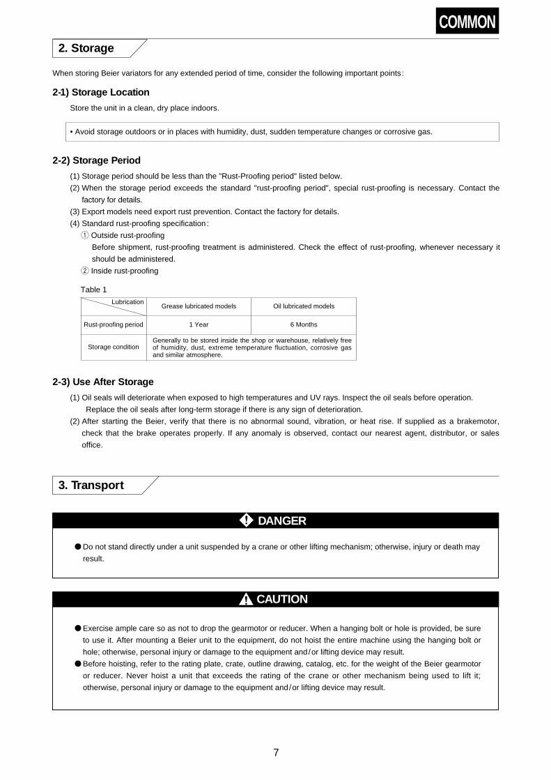
8-4) Oil Supply and Change for Oil-lubricated CYCLO
(1) Oil Change Interval
Table 23 Interval
Table 24 Recommended Lubricating Oil For A Type and B Type BEIER-CYCLO Variator
(3) Oil Quantity
Table 26 shows approx. quantity of oil. Be sure to check the oil level through the oil gauge.
COMMON
Oil supply
Time for lubricatingoil change
Operating conditions
——————
——————
12 hours/day
12 to 24 hours/day
Special conditions such as high temperatures, high humidity, activated gas, etc.
At the time ofpurchase
First time After 500 hours
2nd
onward
Every 6 months
Every 2500hoursEvery 1 to 3months
Oil
chan
ge
(2) Recommended Lubricants
Be sure to use a lubricant recommended by our company.
Recommended lubrication oil is the same for BEIER part and CYCLO part of A Type and B Type BEIER-CYCLO Variator .
Use designated traction oil in Table 18 for BEIER part and use recommended lubrication oil for Cyclo in Table 24 for
D Type BEIER-CYCLO Variator .
Always use correct lubrication oil for both D Type BEIER part and CYCLO part because using mixed or incorrect oil can
affect performance and life significantly.
1 For operation in winter or at a relativery low ambient temperature, use lubricating oils with lower viscosity.
2 Table 25 shows selection standard for viscosity of lubricating oil.
Min allowable viscosity
Max allowableviscosity
Above 15mm/s at oil temp, during operation Viscosity to obtain the oil film needed for transmission of the load
Viscosity that allows CYCLO to start
Viscosity that allows plunger pumps and trochoid pumps to start
Oil bath lubricationmodels less than 4300mm2/s
Forced oil lubricationmodels less than 2200mm2/s
Table 25 Selection Standard for the Oil Viscosity of CYCLO Part
3 To ensure smooth start, use lubricating oil whose pour point is at least 5°C lower than embient temperature.
4 If ambient temperature varies over a wide range, use lubricating oil whose viscosity remains stable or lubricating oil
that will satisfy requirments in Notes 2 and 3 in high viscosity index.
5 When units are always used at an ambient temperature other than 0 to 40°C, consult with the factory because
depending on models it may need to change some parts or preheat or cool lubricating oil.
Table 26 Amount of Lubricating Oil (lit.)
AmbientTemperature
-10°C – 5°C
0°C– 35°C
30°C – 50°C
Shell
Shell Tellus Oil46, 68
Shell Tellus Oil100, C150
Shell Tellus OilC220, C320
Esso
Nuto H 68
Teresso 100, 150
Teresso 320
Mobil
Mobil DTE 25, 26(ISO VG46, 68)
Mobil DTE OilExtra Heavy(ISO VG150)
Mobil DTE OilBB, AA
(ISO VG220, 320)
Single
reduction
Framesize
Horizontal
Vertical
6075
Grease
Grease
6125DB
Grease
Grease
Double
reduction
Framesize
Horizontal
Vertical
6130DB6135DB
6130DC6135DC
6160DA6165DA
6160DB6165DB
6170DB6175DB
6180DA6185DA
6160DC6165DC
1.5
1.0
6170DC6175DC
2.4
1.9
6180DB6185DB
3.5
2.0
6190DA6195DA
5.8
2.7
6190DB6195DB
6.0
2.7
6205DA6205DB
6.0
11
6215DA6215DB
10
14
6225DA6225DB
11
18
6235DA6235DB
17
23
6245DA6245DB
18
29
6255DA6255DB
23
33
6265DA
32
40
6275DB
60
60
6095 6105 6125 6135
0.7
1.1
6145
0.7
1.1
6165
1.4
1.0
6175
1.9
1.9
6185
2.5
2.0
6195
4.0
2.7
6215
8.5
7.5
6225
10
10
6235
15
12
6245
16
15
6255
21
33
6265
29
40
6275
56
60

22
COMMON
Oil supply for Horizontal Type (Refer to Fig.15)
• The standard location of the oil gauge on a horizontal unit is on the right side (viewed from the slow speed shaft side).
However, since the oil gauge may be placed on either side, select the side most convenient for observation.
1 Remove the oil filler plug.
2 Fill oil through oil filler port while checking oil level by the oil gauge.
3 Fill oil the upper line on the oil gauge.
4 Replace the oil filler plug.
Oil supply for Vertical Type (Refer to Fig.16)
1 Remove the oil filler plug and, except for sizes 6255 and 6265 , also remove the airvent.
2 Fill oil through oil filler port while checking oil level by the oil gauge.
3 Fill oil the upper line on the oil gauge.
4 Except for Sizes 6255 and 6265 , apply water proof sealing tape to threads of the air vent plug before re-installing.
5 Replace the oil filler plug.
Fig. 15
Fig. 16
Oil fill level(When drive is
stopped)
Upper line
Lower line
Oil gauge
Plug
Oil fill level(When drive is
stopped)
Upper line
Lower line
Oil gauge
Plug
Oil filler plug
Oil filler port
Oil gauge
Oil filler plug
Oil gauge
Air vent
Oil filler port
(4) Oil Supply
• Be sure to fill with oil when the unit is not operating.
• When the viscosity of oil is high, it may take some time for the oil to settle. Be careful not to over-fill.
(If oil is filled above the upper line, the temperature wil lrise due to the churning heat of the oil.)
• Use the lower red line on the oil gauge, as a guideline for the normal oil level during operation. (Immediately following
commencement of operation, the oil level may fall below the lower red line, but should not be of particular concern,
since the oil level will recover, as the oil viscosity falls due to the drive operation.)
(5) Oil Discharge
Remove the drain plug shown in Fig. 17 or the lower plug of oil gauge shown in Fig. 18 to discharge oil.
Fig. 17 Fig. 18
Oil fill level(When drive is
stopped)
Upper line
Lower line
Oil gauge
Plug
VerticalHorizontal
Oil gauge
Oil gaugePlug
Drain plug
Drain plug

23
(6) Long-term Stoppage
Stoppage Period
Approx. 1 month
More than 1 month
Change the oil and operate the unit for several minutes before stopping the unit.
Flush the unit, fill with rust-preventive oil, and operate the unit without a load for severalminutes before stopping the unit.
• Before starting operation after long-term stoppage, always change the oil. This will ensure that the lubricant is
free from deterioration that may have been caused by long-term stoppage.
Table 27 Long-Term Stoppage
8-5) Grease Replenishment and Change for CYCLO Portion
(1) Grease Replenishment /Change Interval
Model Grease supply /change interval
Maintenance-free series( section in Table 11, 12 on
page 17)
Long-life grease (ALVANIA GREASE RA) is supplied withthese models, so operation can continue for extendedperiods. However, disassembly to change the grease after20,000 hr or 3 to 5 years operation will ensure longerservice life.
Grease-lubricated models otherthan maintenance-free
Refer to Tables 29 and 30 for supply and change ofgrease.
Table 28 Grease Supply/Change Intervals
Hours ofoperation
10 hr max. /day
10–24 hr /day
Replenishmentinterval
3–6 months
Remarks
Reduce the supply inter-val when the operatingconditions are severe orthe frame size is large.
Change interval
Every 20,000 hr or3–5 years
Remarks
Reduce the supply inter-val when the operatingconditions are severe orthe frame size is large.500–1,000 hr
Table 29 Grease Replenishment Interval(Excl. maintenance-free type)
Table 30 Grease Change Interval(Excl. maintenance-free type)
(2) Recommended Grease
Table 31 Recommended Grease
Ambient
temperature
(°C)
-10~50
Model
i) Maintenance-free series( section in Table 11,12 on page 17)
ii) Other grease model
Shell Cosmo Oil Shell
ALVANIA GREASERA
COSMO GREASEDYNAMAX SH No.2
ALVANIA GREASE2
• Do not use any grease other than those shown in Table 31.
• Models ii) in Table 31 are filled with COSMO GREASE DYNAMAX SH No.2 before shipment from our factory.
• The two kinds of grease for ii) in Table 31 may be mixed with each other.
• When the ambient temperature continuously exceeds the range of 0~40°C, modifications are needed.

24
(3) Quantity of Grease
Table 32 shows the quantity of grease required when grease needs to be changed. Approximately 1/3~1/2 of the
volume for the 1st stage reduction portion is appropriate when grease needs to be replenished.S
ingl
ere
duct
ion
Dou
ble
redu
ctio
n
Frame size 606 607 608 609 610 611
Reductionportion Qty of grease (g) 25 25 65 90 140
Slow speed shaftbearing portion Qty of grease (g) 35 35 70 100 100
200
90
612
330
120
Frame size 606 DA 607 DA 609 DA 610 DA 612 DA 612 DB 613 DA 613 DB 613 DC 614 DA 614 DB 614 DC 616 DA 616 DB 616 DC 617 DA 617 DB 617 DC
1st stage(I/P side)reductionportion
Qty of grease (g) 25 90 25
2nd stage(O/P side)reductionportion
Qty of grease (g) 25 90 140 330 450 750 1000
500
2nd stage (O/Pside) slow speed
shaft bearingportion
Qty of grease (g) 35
618 DA 618 DB 619 DA 619 DB 6205DA 6205DB 6215DA 6215DB 6225DA 6225DB 6235DA 6235DB 6245DA 6245DB 6255DA 6255DB 6265DA
1100
140 450 330 450 330 450 750 450 1000 750 1100 750 1100 1000 1500 1500
1500 1500 2000 2500 4000 4500 6000 8000
600 700 700 800 900 1000 1100 1200 1300
35 100 100 120 300
Frame size
1st stage(I/P side)reductionportion
Qty of grease (g)
2nd stage(O/P side)reductionportion
Qty of grease (g)
2nd stage (O/Pside) slow speed
shaft bearingportion
Qty of grease (g)
90 140 25 90 140 90 140 330 90 140 330
• : Maintenance-free Series• Space/volume ratio : Ratio of grease to the volume of space• 0, 5, or H is inserted in .
Table 32 Qty of Grease
COMMON
(4) Supply and Discharge of Grease
Procedure for supplying grease for grease-lubricated models (excl. maintenance-free type)
1 Remove the grease discharge plug from the outside cover.
2 Supply grease with a grease gun through the grease nipple in the inside cover section or motor connection cover.
3 Replace the grease discharge plug.
Fig. 19 Location of Grease Discharge Port
• Fill with grease during operation to ensure proper, uniform circulation.
• Fill with grease slowly.
• Grease supply exceeding the quantity shown in Table 32 will cause temperature rise from agitation heat or leakage
of grease into BEIER part.
• Apply grease liberally to bearings (especially to eccentric bearings), pins, rollers, and toothed section of the cyclo
discs. (Refer to 13–3. Drawing on page 36.)
Grease nipple (for CYCLO)
Oil filler plug (for BEIER)
Drain plugOil gauge
Drain plug
Horizontal BEIER-CYCLO VARIATORwith Grease Lubricated Cyclo

25
8-6) Maintenance of Variator Bearing
• Maintenance of bearing is needed for BEILER vertical A Type and B Type .
• Replenish grease from grease nipple (Fig 30 on page 35.)
Table 33 Interval
(2) Recommended Grease
Table 34 Recommended Grease
Ambienttemperature
-10–50
Shell Cosmo Oil
ALVANIA GREASE RACOSUMO GREASEDYNAMAX SH No.2
• Do not use any grease other than those shown in Table 34.
(4) Supply and Discharge of Grease (Refer to Fig.30 Construction on page 35)
Replenish the new grease from the grease nipple during the operation.
(Replenishing grease while BEIER is nonoperational may cause insufficient grease exchange.)
(1) Interval
• Excessive grease may cause temperature rise of the bearing or leakage of the grease.
• Do not extend the replenishing interval by supplying more than the prescribed amount of grease.
• Omitting to replenish grease at the start or periodically may result in abnormal abrasion, noise, and breakage of the
bearing.
(3) Grease Quantity
Table 35 Amount of Grease to Be Replenished on Open Bearing
Frame size
BE
IER
Aan
dB
Typ
e(v
ertic
al)
N10A N8B
15A 10B
20A 15B
30A 20B40A 30B
50A 50B75A 75B
100A
150A 100B200A 150B
Basic typeBEIEL-CYCLO Variator
For output shaft
Bearing No.
6208NR
6310NR
6313NR
22217BK
23024BK
23128BNR
20
35
25
35
100
NU312
NU314
NU317
—
—
30
40
55
—
—
6315Z
6317Z
6320Z
—
—
45
55
70
—
—
5 — — — —
Qty of grease (g)Input shaft side
Bearing No. Qty of grease (g) Bearing No. Qty of grease (g)
Output shaft side
For slow speed shaft
With built-in gear
• Replenish the amount of grease in the table above to the bearings.
• Replenish grease at least every three years even if you use the unit with the intermittent opration.
• After a long suspension, replenish grease right after starting the operation.
COMMON
Hours ofoperation
10 hr max. /day
10–24 hr /day
Replenishmentinterval
3–6 months
Remarks
Reduce the supply inter-val when the operatingconditions are severe orthe frame size is large.500–1,000 hr

26
8-7) Maintenance of Motor Bearing
The maintenance for Sumitomo standard 3-phase motor is shown below.
(Refer to the respective instruction manuals for the brakemotor , other companies' motor , etc.) Bearing No. and
maintenance methods also differ according to motor size. Before maintenance, check the bearing type on the rating plate
and Table 36.
Bearing type
Shield bearing
Motor frame sizeNote
No grease nipple
Load side Opposite side
Smaller than #225 Smaller than #250
Open bearing With grease nipple and discharge plugBigger than #250 —
Table 36 Bearing Type
Grease replenishment for open bearing(1) Grease Replenishment Intervals and Quantity
Check the bearing No, on the rating plate, refer to Table 37 and supply grease.
Bearing No.Dimension (mm) Initial q'ty
(g)Replensihed
q'ty (g)
Grease replenishment interval (h) for each rotation speed (r/min) of motor
750r/min 900r/min 1000r/min 1200r/min 1500r/min 1800r/minI. D O. D W
6314 70 150 35 200 40 8500 7000 6000 5000 3500 2500
6315 75 160 37 230 45 8500 6500 6000 4500 3500 2500
6316 80 170 39 260 50 8000 6500 5500 4500 3000 2500
6317 85 180 41 300 55 7500 6000 5000 4000 3000 2000
6318 90 190 43 350 60 7000 5500 5000 4000 2500 2000
6319 95 200 45 400 65 7000 5500 4500 3500 2500 1500
6320 100 215 47 450 70 6500 5000 4500 3500 2000 1500
6321 105 225 49 500 75 6000 5000 4000 3000 2000 1500
6322 110 240 50 550 80 6000 4500 4000 3000 2000 1000
6324 120 260 55 700 100 5500 4000 3500 2500 1500 1000
6412 60 150 35 200 40 8500 7000 6000 5000 3500 3000
6413 65 160 37 230 45 8000 6500 6000 4500 3500 2500
6414 70 180 42 300 55 8000 6500 5500 4500 3000 2500
NU314 70 150 35 120 40 4000 3500 3000 2500 1500 1000
NU315 75 160 37 150 45 4000 3000 3000 2000 1500 1000
NU316 80 170 39 200 50 4000 3000 2500 2000 1500 1000
NU317 85 180 41 250 55 3500 3000 2500 2000 1500 1000
NU318 90 190 43 300 60 3500 2500 2500 2000 1000 1000
NU319 95 200 45 350 65 3500 2500 2000 1500 1000
NU320 100 215 47 400 70 3000 2500 2000 1500 1000
NU321 105 225 49 450 75 3000 2500 2000 1500 1000
NU322 110 240 50 500 80 3000 2000 2000 1500 1000
NU324 120 260 55 650 100 2500 2000 1500 1000
21312 60 130 31 70 30 1500 1000 1000 800
• "Initial q'ty" shows quantity of grease for disassembled and cleaned inside of the unit. Paint 1/3 of grease with theinner lace of bearing and replenish other with inside of the unit.
• "Replenished q'ty" shows quantity of grease for every replenishment.• For intermittent operation, replenish grease every 3 years or less.• For long-term stoppage replenish grease just after operating.
Table 37 Grease Replenishment Intervals and Quantity for Open Bearing
Maintenance of shield bearing
Shield bearing is supplied with good lubricating grease in advance. Although grease replenishment is not necessary,
exchange of bearing every 20,000 operational hours or once in 3-5 years in normal operating condition at the time of
overhaul, enables more unfailing operation.
• Use CM class (clearance) bearing for the motor bearing.
• Use grease (Kyodo Yushi : Multemp SRL) lubricated bearing for the sealed motor bearing.
• Reduce the supply interval when the operating conditions are severe.

27
Maintenance of V ring in outdoor type motor
Under aging phenomena or by abrasion, the V ring may become less water-proof.
Exchange the V ring once every three years under the normal operation. Refer to the dimension in Table 39 for V ring
attaching dimension.
V Ring
V-10A–V-18A
V-20A–V-38A
V-40A–V-65A
V-70A–V-100A
Dimension B1
4.5 mm
6 mm
7 mm
9 mm
Remarks
Table 39 V Ring Attaching Dimension
B1
• At exchange, apply a small amount of grease to the lip of the V ring.
• We recommend the V ring made by Forsheda.
(2) Recommended Grease
Ambienttemperature
°C
-10~40 Alvania Grease 2 Darina Grease 2
Open bearing
E, B Insulation F Insulation
Shell Oil
Table 38 Recommended Grease
• Do not use any grease other than those shown in Table 38.
(3) Grease Supply and Discharge (Refer to Fig.20)
1 Remove the discharge plug, discharge old grease and add new grease while unit is operating.
(Grease replenishment at rest cause an insufficient grease change.)
2 Replace the discharge plug after 10min operation.
• Excessive grease may cause temperature rise of bearing or leakage of grease.
• Exceeding the recommended amount of grease does not extend the replenishment interval.
• Don't neglect daily inspection; otherwise abnormal wear and noise from the motor, damage to the bearing may result.
1 Variator side
Fig. 20 Construction of Open Bearing in the Motor
2 Motor end side
End bracket
Motor shaft
Bearing
Bearing cover
Outlet
Motor shaft
BearingBearing cover
BEIER CYCLO flange bracket
Outlet
Gear side
Grease nipple Grease nipple
Oil seal

28
9. Lubricating Oil Cooling Device
9-2) Cooling Water
• For cooling water, use city water or industrial water.• Table 39 gives a guideling for amount of cooling water supply. Adjust this amount depending on ambient temperature
and operating conditions. It is desirable that Beier Variator be operated with its casing temperature kept within about60°C .
9-3) Instructions on Starting
• Before starting the main body, be sure to start the oil pump of the lubricating oil cooling device and confirm lubrication.Allow 30 to 60 seconds lead time for the pump motor, and start the main motor only after the lubricating oil is circulatingwell. For the wiring, refer to the diagram on Fig. 11 page14.
9-1) Installation
• Install the horizontal-type Beier Variator horizontally, install the vertical-type Beier Variator vertically, and install thelubricating oil cooling device horizontally.
• Install this device as close as possible to the main body of the Beier Variator. If it is installed too far apart, the oil pumpwill suffer faulty suction and excessive noise, temperature, and insufficient lubrication will result.
• If air is sucked only halfway out of the suctionside piping of the oil pump, the amount of oil will be reduced as a result ofthis insufficient suction, thereby causing excessive noise in the oil pump. For this reason, airtightness must bemantained.
(1) Install this device within 0.5m in a vertical upward location, or within 1.5m in a vertical downward location, and within 3m
horizontally from main body of the Beier Variator. Minimize pipe bands.
(2) The outline diagram shows both the Beier Variator and its lubricating oil cooling device. According to Fig. 21, install
piping at the site along the broken lines. Use a gas pipe for the piping. Use a 1-1/2B to 2B gas pipe for the Beier Variator
oil outlet, and use a 1B gas pipe for the oil inlet.
Piping materials and pipe joints should be provided by the user since such piping will be installed at the site.
Motor
Oil inlet Oil inlet
Cooling water outletCooling water intlet
Corrosion preventive zinc rod
Cooling water outletCooling water intlet
Corrosion preventive zinc rod
Oil filterOil outlet
Oil outlet
Oil cooler
Corrosion preventive zinc rod
Trochoid pump
Pressuregauge
Pressuregauge
Oil filter
Oil cooler
Trochoid pump
Corrosionpreventivezinc rod
Fig. 21
Lubrication oil cooling device is standard attachment to Beier frame size 50A – 200A, 50B – 150B .
COMMON

29
9-4) Daily Inspection and Maintenance of Oil Cooling Device
Table 40 Amount of Cooling Water Supply
Beier frame size
50A, 75A, 100A50B, 75B
Holizontal Model
Amount of watersupply (lit/min)
6–8
10–15
15–20
Vertical Model
150A200A100B150B
(2) Maintenance
(a) Filter cleaning
(i) Clogged filter cartridge may cause the abnormal noise by oil suction shortage of the oil pump. Continuing the
operation under this state may result in supplying shortage of the oil to the variator as well as breakdown of the oil
pump, and may consequently bring the variator itself to burning and other problems.
(ii) Since the filter cartridge is a laminate, you can easily clean the clogged cartridge by turning the handle at the upper
end of the filter. Be sure to turn the handle once or more.
(iii) At the initial operation, since it is easy to clog the cartridge, turn the handle once or more a day for cleaning the
cartridge.
(iv) At a standstill, drain the accumulated dust in the lower part of the filter from the drain plug at the lower end.
(b) Inspection and cleaning of the oil cooler (cf. Fig.22)
(i) Maintenance and cleaning the oil cooler of the lubricating oil cooling device periodically. The interval depends on the
condition of the lubricating oil or the quality of the cooling water. Be sure to conduct the periodical inspection every 3
to 6 months.
(ii) You can check the cooling water by removing a bonnet in the U-turn side of the cooling water. For checking the
lubricating oil, drain the oil from the oil drain plug.
(iii) At that time, be sure to check the corrosion preventive zinc rod for wear. Replace the rod if it has been worn to less
than half of its original length. You may have to replace it 3 to 6 months depending on the quality of the cooling
water. (There are zinc rods at three places.)
(iv) In winter when you stop the operation at the place where the cooling water freezes, surely drain the water every day.
Even at the ambient temperature that the cooling water freezes, if you can keep the casing temperature of the variator
between 40 to 45 degree, reduce the amount of the cooling water or stop supplying the cooling water.
(1) Daily Inspection
Check the items below to evaluate whether cooling device is operating normally.
1. Is cooling water flowing normally?
2. Is oil clirculating?
3. Is the temperature of BEIER case at 60°C or lower most of the time?
Oil drain plug
Bonnet in the inlet and outlet side of waterBonnet in the U-turn side
Fig. 22 Oil Cooler
COMMON
30
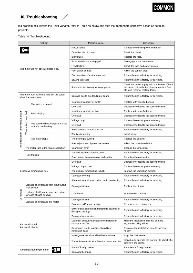
10. Troubleshooting
If a problem occurs with the Beier variator, refer to Table 40 below and take the appropriate corrective action as soon as
possible.
Problem Possible cause Correction
Power failure
The motor will not operate under load.
The motor runs without a load but the outputshaft does not rotate.
Whe
na
load
isap
plie
d
The
outp
utsh
aftt
urns
with
outa
load
The switch is heated.
Fuse tripping
The speed will not increase and themotor is overheating.
The motor stops.
The motor runs in the reverse direction.
Fuse tripping
Excessive temperature rise
Oil
leak
age
Leakage of oil /grease from input/outputshaft section
Leakage of oil /grease from the contactsurfaces of case or cover
Leakage of oil /grease into motor
Abnormal soundAbnormal vibration
Abnormal sound from motor
Contact the electric power company.
Defective electric circuit Check the circuit.
Blown fuse Replace the fuse.
Protective device is engaged Disengage protective device.
Load locking Check the load and safety device.
Poor switch contact Adjust the contact area.
Disconnection of motor stator coil Return the unit to factory for servicing.
Bearing is broken Return the unit to factory for servicing.
3-phase is functioning as single-phase.Check the power supply with a voltmeter. Checkthe motor, coil in the transformer, contact, fuse,etc. and repair or replace them.
Damage due to overloading of gears Return the unit to factory for servicing.
Insufficient capacity of switch Replace with specified switch.
Overload Decrease the load to the specified value.
Insufficient capacity of fuse Replace with specified fuse.
Overload Decrease the load to the specified value.
Voltage drop Contact the electric power company.
Overload Decrease the load to the specified value.
Short-circuited motor stator coil Return the unit to factory for servicing.
The key is missing Install a key.
The bearing is burned. Replace the bearing.
Poor adjustment of protective device Adjust the protective device.
Connection error Change the connection.
The outlet wire is short-circuited. Return the unit to factory for servicing.
Poor contact between motor and starter Complete the connection.
Overload Decrease the load to the specified value.
Voltage drop or rise Contact the electric power company.
The ambient temperature is high. Improve the ventilation method.
Damaged bearing Return the unit to factory for servicing.
Abnormal wear of gear or disc due to overloading Return the unit to factory for servicing.
Damaged oil seal Replace the oil seal.
Loose bolts Tighten bolts correctly.
Damaged oil seal Return the unit to factory for servicing.
Excessive oil /grease supply Remove excess oil /grease.
Entry of dust and foreign matter into bearings ordamaged bearings.
Return the unit to factory for servicing.
Damaged gear or disc. Return the unit to factory for servicing.
Distortion of housing because the installationsurface is not flat
Make the installation base flat or makeadjustment using shims.
Resonance due to insufficient rigidity ofinstallation base
Reinforce the installation base to increaserigidity.
Nonalignment of shaft with driven machine Align the shaft centers.
Entry of foreign matter Remove the foreign matter.
Damaged bearings Return the unit to factory for servicing.
Transmission of vibration from the driven machineIndividually operate the variator to check thesource of the sound.
Table 40 Troubleshooting
COMMON

31
OP11. Remote Control Equipment (OPTION)
11-1) Speed Control Device
(2) Handling of the Pilot Motor (PM)
Both worm gear-type and Cyclo Drive-type pilot motors are available to match the different Beier types.
· Never conduct operations while the Beier Variator is stopped.
(1) Checking Wiring and Speed Control Operation
· An example of control circuit for pilot motor and push button is shown in Fig. 23 . To check the connection, start the
main motor first. Then, confirm that the revolution speed of output shaft increases while depressing the speed
increase button (PB4). Also confirm that the revolution speed of output shaft decreases while depressing the speed
decrease button (PB3). If the operation is reversed, interchange two phases of power supply to the pilot motor (PM).
· When highest speed or lowest speed has been reached, check to confirm slip clutch is idling, thereby positively
protecting both PM and speed change control device.
· Handling of the worm gear-type pilot motor (PM)
This pilot motor is a maintenance-free motor, which incorporates a ball clutch as a safety device.
To remove the pilot motor from the Beier main body, pull out the PM mounting bolts (3 bolts ) first.
Then pull out the whole PM from the operating shaft. If it becomes necessary to change the manual speed, shut off the power
of the pilot motor, and use a hexagon bar wrench (nominal 5) to turn part A.
PM
THR
M
MC1
THR
NFB1 NFB2
R S T R S T
MC2D MC2U
ControlPowerSupply
R1PB5
PB1
PB2 PB3 PB4S1
MC1
MC1
MC2U
MC2U
MC2D
MC2DMC2D
THRTHR
Fig. 23 Connection Diagram
NFB : Auto Breaker
MC1 : Electromagnetic Switch (Main Motor)
MC2D : Electromagnetic Switch (PM, Speed Decrease Side)
MC2U : Electromagnetic Switch (PM, Speed Increase Side)
PB1 : Start Button
PB2 : Stop Button
PB3 : Speed Decrease ButtonPB4 : Speed Increase ButtonPB5 : Emergency Stop ButtonM : Main MotorPM : Pilot MotorTHR : Thermal Protection Relay
Table 42 Beier Type and Pilot Motor Type
Worm gear motor type Cyclo Drive type
A Type N02A, N05A, N1A, N2A, N3A, N5A, N8A, N10A 15A, 20A, 30A, 40A, 50A, 75A, 100A, 150A, 200A
B Type N02B, N05B, N1B, N2B, N3B, N5B, N8B 10B, 15B, 20B, 30B, 50B, 75B, 100B, 150B
D Type N05D, N1D, N2D, N3D, N5D, N8D, N10D
• There is a possibility of speed control failure if clutch is left slipping for 30 seconds or more while speed controloperation is sustained at maximum or minimum speed. Do not fail to stop PM as soon as possible by releasingpushbutton for control. To prevent such problem, check change in rotation speed using electromagnetic tachometerwhile conducting speed control operation.
• For cases when clutch stays slipping because of the content of speed control, optional limit switch system isrecommended.
• When stopping Beier Variator, never turn speed control handwheel. For Beier with remote control, connect powersource of speed control pilot motor from the secondary side of power source of main motor.

32
OP
· Setting torque of slip clutch for Cyclo Drive type
Torque of slip clutch has been set at the time of delivery by taking into consideration required moment of control shaft
of Beier Variator, strength of inserted bush (mounting screws), etc. Therefore, no further adjustment is required
except for special cases such as wear due to extended use. If need should arise to reestablish torque after delivery
for some particular reason, proceed with the following steps referring to Fig. 25: Screw in adjusting nut 7 for full free
length of spring 5 and set lock plug 6. Next, completely screw in adjusting bolt !0 into adjusting nut 7.
With these steps, required turning force should be obtained. If any fine adjustment is needed, this can be
accomplished by sliding position of adjusting nut 7 back and forth.
Fig. 25
PM Mounting Bolt
PM Flange
Bushing for PM
Operating shaft for PM
PM Output Shaft
Part A
Spring Pin
Fig. 24
· Slip clutch is designed to be used in dry condition. Therefore, take extra care to keep clutch free from splashes of water,
oil, etc.
Part No. Description Q'ty
1 Handwheel 1
2 Grip 1
3 Spring pin 1
4 Slip clutch 1
5 Spring 1–2
Part No. Description Q'ty Part No. Description Q'ty Part No. Description Q'ty
6 Lock plug 2
7 Adjust nut 1
8 2
9 Chain wheel 1
10 Adjust bolt 3
11 Bush 2
12 Spacer 2
13 Indicator plate 1
14 Gasket 1
15 Pointer 1
16 Shifting nut 1
17 Indicator Holder 1
18 Gasket 2
19 Oil seal 2
20 Socket 1
Jaw clutch

33
OP11-2) Speed indicators
(2) Connect the auxiliary power source to the two tachometer terminals.
Auxiliary power specification
Analog tachometer : Common for AC100V 50/60Hz, AC200V 50/60Hz
Digital tachomenter : AC100V 50/60Hz
This tachometer has graduated output revolutions.
(3) For use of explosion proof type, refer to the Speed Setter SP-20D catalog.
• Use a twisted shield wire measuring 0.5mm2 or more for the wiring. Separate the shield wire from the power line. The
connection distance must be no more than 100m.
Electromagnetic tachometer (for non explosion proof type).
(1) Connect the lead wire of the Beier Variator electromagnetic sensor to the two tachometer terminals. When shield
wire is used with digital tachometer, shield can be connected to the (–) side of sensor input. For analog tachometer,
connection of shield is not necessary. (Assess whether or not to connect the shield wire since the noise intensity may
become greater if unconnected.)
Electromagneticsensor
Sensor gear
Fig. 26
Fig. 27 Type CCF-10P Fig. 28 Type SDT-49T
[Analog Tachometer] [Digital Tachometer]
48
96
Panel cut
Connection
Sensorinput
AC100VPowersouce
Scale factor setter
1 0.1 0.01 0.001
92 +0.80
45+
0.6
0
(+) (–)
M3 terminal screw
7
Panelthickness5max.
131+Panel thickness
131147
106 100
32±0.5 32
91067
12345 8
±0.5
32±0
.532
±0.5
32±0
.532
±0.5
32
4-4 mmdiameterhole
Panel cut
±0.5 32±0.5
M3 terminal screw
4
83
4-M3
0.512.5 100
dia.
65
dia.67
12345
Wiring diagram
Sensorinput
AC200VAC100V
Auxiliarypower
910678

34
OP11-3) Operating instructions
• Change speed only after starting Variator. Never attempt to perform speed change operation when the unit is at a
standstill.
To prevent such erroneous operation, it is recommended that power to pilot motor (PM) be obtained from secondary side
of main motor power supply. (Refer to Fig. 23 on page 31)
(1) Starting
• Stopping main motor during speed change operation can break discs or cause other trouble. Therefore, before
opening switch for main motor, disconnect speed change operation circuit without fail.
In this case, erroneous operation can be prevented by making connection as shown in Fig.23 on Page 31.
(2) Speed change
Pilot motor (PM) will run and speed change will take place while pushbutton switch for speed change control is being
pressed. When desired revolutions have been reached, release pushbutton switch to stop PM. Then Variator will run at
a constant speed thereafter. To reverse PM (for instance, in order to switch from acceleration to deceleration), depress
pushbutton again for desired operation after PM has come to a stop.
(3) Stopping
12. Speed Setter
Speed setter is automated control device that can control variator by rotation speed feedback system, which sets desired output
rotation speed by digital switch or electronic signal DC4-20mA.
Refer to Speed Setter SP-20D Operating Manual for handling instructions.

35
13. Construction
13-1) Basic A and B Type BEIER VARIATOR (Horizontal)
7
4141332
9
8
5
6
11
12 10
11615 G-3
G-1
D-3
D-1 G-2
Fig. 29
13-2) Basic A and B Type BEIER VARIATOR (Vertical)
7
12
G-2 G-3
D-3
G-1
D-1
10
3
16
9
11
A
2
14
13
1
8
Fig. 30
AFrame sizes equiped with grease nipple are shown on page 25.
COMMON
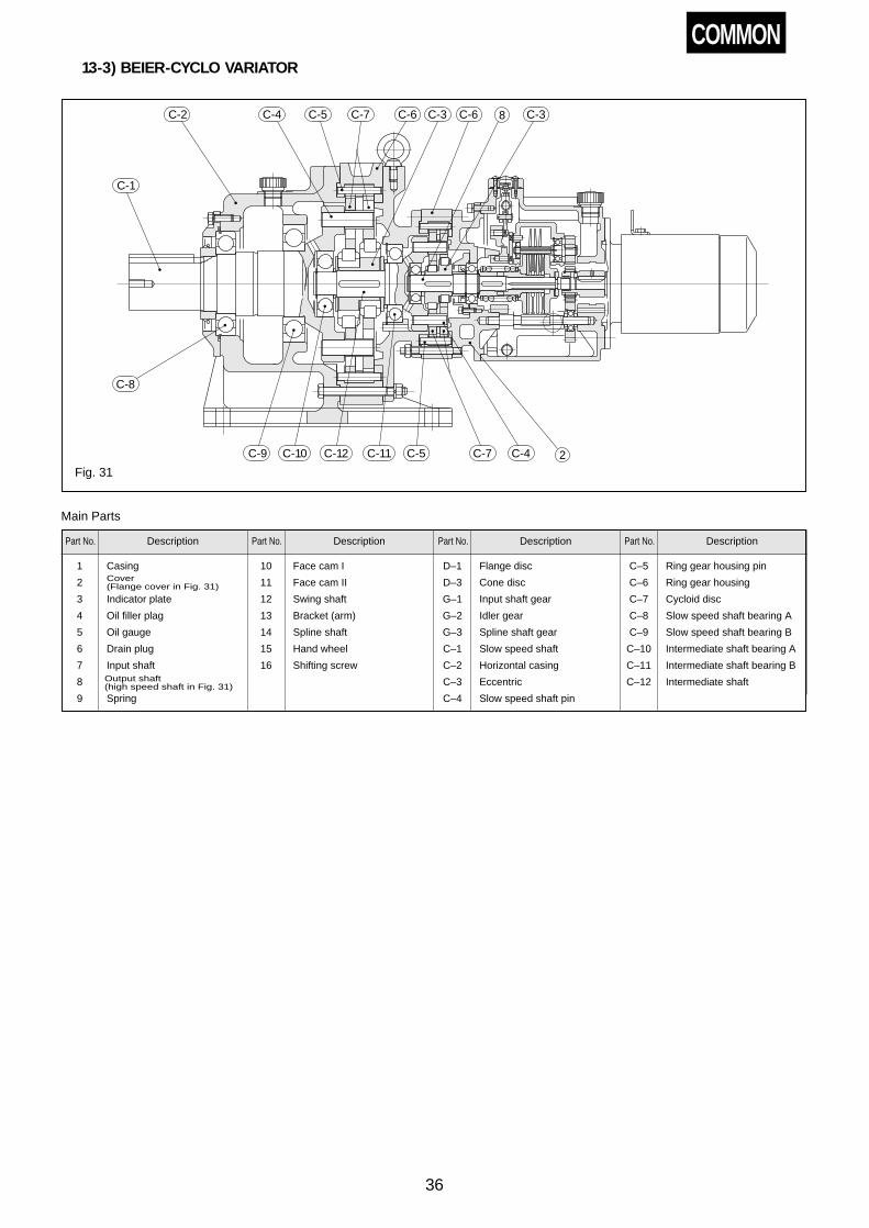
36
13-3) BEIER-CYCLO VARIATOR
2
8C-2 C-4 C-5 C-7 C-6 C-3 C-6 C-3
C-1
C-8
C-9 C-10 C-12 C-11 C-5 C-7 C-4
Fig. 31
Part No. Description
Main Parts
1 Casing
2
3 Indicator plate
4 Oil filler plag
5 Oil gauge
6 Drain plug
7 Input shaft
8
9 Spring
Part No. Description Part No. Description Part No. Description
10 Face cam I
11 Face cam II
12 Swing shaft
13 Bracket (arm)
14 Spline shaft
15 Hand wheel
16 Shifting screw
D–1 Flange disc
D–3 Cone disc
G–1 Input shaft gear
G–2 Idler gear
G–3 Spline shaft gear
C–1 Slow speed shaft
C–2 Horizontal casing
C–3 Eccentric
C–4 Slow speed shaft pin
C–5 Ring gear housing pin
C–6 Ring gear housing
C–7 Cycloid disc
C–8 Slow speed shaft bearing A
C–9 Slow speed shaft bearing B
C–10 Intermediate shaft bearing A
C–11 Intermediate shaft bearing B
C–12 Intermediate shaft
COMMON
Cover (Flange cover in Fig. 31)
Output shaft (high speed shaft in Fig. 31)

37
13-4) D Type BEIER VARIATOR (Horizontal)
417
16
6
7
9 3 10 1
10131112
14 5 815D-1D-3
D-3D-1Fig. 32
Part No. Description
Main Parts
1 Casing
2 Base
3 Cover
4 Indicator plate
5 Oil filler plug
Part No. Description Part No. Description Part No. Description
6 Oil gauge
7 Drain plug
8 Input shaft
9 Output shaft
10 Spring
11 Face cam I
12 Face cam II
13 Swing shaft
14 Bracket (arm)
15 Spline shaft
16 Hand wheel
17 Shifting screw
D–1 Flange disc
D–3 Cone disc
13-5) D Type BEIER VARIATOR (Vertical)
D-3
D-1
D-1
D-3
5
6
15
14
16
4
17
10
1
7
2
9
12
11
13
10
8
Fig. 33
COMMON

38
13-6) Motor
Fig 34 Example of Construction of 80–112M Frame
No. Part Name
Main Parts
1 Bearing cover
2 Motor shaft bearing B
3 Fan
4 Fan cover
5 End bracket
6 Rotor conductor short circuit ring
No. Part Name No. Part Name
7 Rotor core
8 Stationary core
9 Stator trame
10 Stator windings
11 Eyebolt
12 Flange bracket
13 Motor shaft bearing A
14 Oil seal
15 Motor shaft
16 Conduit box

39
14. Oil Seal list
Type
Common
For input shaft
Nominal No. Q'ty
S25408For free
input shafttype only
N02AN05AN1A
N02BN05B
1
For shifting screw
Nominal No. Q'ty
For output shaft
Nominal No. Q'ty
For slow speedshaft CYCLO
Type
6075609561056125
S22325
S25356
2
2
D30478
D659013
1
D507212 1
1
Nominal No. Q'ty
S26428 1
P10A-O-ring(10 14 2.4)P18-O-ring(18 22 2.4)G10204
2
2
2
S25408 1
S35508For free
input shafttype only
S45629
S45629
S628512
N2AN3A
N5AN8A
N10A
15A
N1BN2B
N3BN5B
N8B
10B
1
1
1
1
6125
6160, 61656170, 61756180, 61856170, 61756180, 61856190, 61956180, 61856190, 6195
62156225
–
–
–
–
–
–
–
–
–
6130, 61356145
6160, 6165
S385811
S45629
S45629
S50689S50689S60759S608212
S659012
S8511013S8010010
1
1
1
1111
1
11
D659013
D8511013D8511013D9513015D11014515D9513015D11014515D12015516D11014515D12015516D13016014D14517514
–
–
–
1
D658812 1
11111111111
–
–
–
S385811
S507010
S507212
S558514
1
1
1
1
P10A-O-ring(10 14 2.4)P18-O-ring(18 22 2.4)G10204
P14-O-ring(14 18 2.4)S14246
S17306
S17306
2
2
2
2
2
2
2
S355511
S457014
S608212
S709212
S8511013
S10012513
S11014014
S11014014
20A
30A40A
15B
20B30B
150A200A
100B150B
50B75B
50A75A
100A
1
1
1
1
S609014
S659012
S11014014
S14017014
1
1
1
1
S17306
S22388
S254010
S355511
2
2
2
2
S8511013
S10012513
S12515514
–
1
1
1
1
1
1
1
–
For high speedshaft
Nominal No. Q'ty
For low speedshaft
Nominal No. Q'ty
Basic Type Gear RecuctionType BEIER-CYCLO VARIATOR
A&
BT
ype
BE
IER
VA
RIA
TO
R(H
oriz
onta
l)A
&B
Typ
eB
EIE
RV
AR
IAT
OR
(Ver
tical
)
–N05AN1A N05B
–S26428G26426
11
P10A-O-ring(10 14 2.4)P18-O-ring(18 22 2.4)G10204
2
2
2
S32458 2
–
S45629
N2AN3A
N5AN8A
N1BN2B
N3BN5B
–
1
S40587
S40587
2
2
P10A-O-ring(10 14 2.4)P18-O-ring(18 22 2.4)G10204
P14-O-ring(14 18 2.4)S14246
2
2
2
2
2
S385811
S456812
2
2
S45629N10A N8B 1 S507212 2S17306 2 S608212 2S62851215A 10B 1 S558514 1S17306 2 S8511013 1S851101320A 15B 1 S609014 1S17306 2 S10513514 1
S1101251330A40A
20B30B 1 S659012 1S22388 2 S11014014 1
S1101401450A75A
100A
50B75B 1 S10513514 1S254010 2 – –
S11014014150A200A
100B150B 1 S14017014 1S355511 2 – –
Table 43 Oil Seal List
60956105
S22325 2 D507212 1
6125 S25356 2 D659013 1
DT
ype
BE
IER
VA
RIA
TO
R(H
oriz
onta
l)
S25458N05DN1D
1 S26428 1
P10A-O-ring(10 14 2.4)P18-O-ring(18 22 2.4)G10204
2
2
2
– –
6095
S26428 1D507212 1
1
61256130, 6135 S38588
S45629
S45629
S50689
2
2
2
2
D659013
D8511013D8511013D9513015D11014515
1
2222
61456160, 61656160, 61656170, 61756180, 6185
– – – ––– – – ––– – – ––
– – – ––
– – – ––
– – – ––
D658812 2
6105
6125 D659013
6095
S26428 2D507212 1
1
6105
6125 D659013
S35508N2DN3D
1 S32528 1
P10A-O-ring(10 14 2.4)P22-O-ring(22 26 2.4)G10257
2
2
2
– –
6130, 6135
S38588 1D658812 1
1
6145
6160, 6165 D8511013
6130, 6135
S38588 2D658812 2
2
6145
6160, 6165 D8511013
S45629N5DN8D
1 S35508 1
P14-O-ring(14 18 2.4)P26-O-ring(26 32 3.5)S14246
2
2
2
– –
6160, 6165
S45629 1
D8511013 1
1
1
6170, 6175 D9513015
6180, 6185 D11014515
6160, 6065
S45629 2
D8511013 2
2
2
6170, 6175 D9513015
6180, 6185 D11014515
S55729N10D 1 S45629 1
2017-O-ring(17 21 2.4)P29-O-ring(29 35 3.5)S17306
2
2
2
– –
DT
ype
BE
IER
VA
RIA
TO
R(V
ertic
al)
S25458N1D 1 S25458 2
P10A-O-ring(10 14 2.4)P18-O-ring(18 22 2.4)G10204
2
2
2
– –
S35508N2DN3D
1 S305512 2
P10A-O-ring(10 14 2.4)P22-O-ring(22 26 2.4)G10257
2
2
2
– –
S45629N5DN8D
1 S35508 2
P14-O-ring(14 18 2.4)P26-O-ring(26 32 3.5)S14246
2
2
2
– –
S55729N10D 1 S45629 2
2017-O-ring(17 21 2.4)P29-O-ring(29 35 3.5)S17306
2
2
2
– –
6170, 6175
S527512 1
D9513015 1
1
1
6180, 6185 D11014515
6190, 6195 D12015516
6170, 6175
S527512 2
D9513015 2
2
2
6180, 6185 D11014515
6190, 6195 D12015516
COMMON

40
15. Bearing list
Common
For input shaft
Basic Type Gear Reduction Type
A&
BT
ype
BE
IER
VA
RIA
TO
R(H
oriz
onta
l)A
&B
Typ
eB
EIE
RV
AR
IAT
OR
(Ver
tical
)
Table 44 Bearing list
DT
ype
BE
IER
VA
RIA
TO
R(H
oriz
onta
l)D
Typ
eB
EIE
RV
AR
IAT
OR
(Ver
tical
)
Type
N02AN05AN1A
N02BN05B
6003For free
input shafttype only
2HK0509T2
HK091033
– –AXK1105AS1105
12
6305NR6305
For freeinput shafttype only
11
6296202
33
6201 3AXK1107AS1107
6202
121
6307NR6209
11
63006203
33
6202 6 6302 1
6307NR6210
11
63006203
33
6202 6 6304 1
6210NR6212
11
63036305
33 6204 6 6305 1
6213NR6213
11
63036403
33 6006 6 6306 1
63146316
11
64046405
33 3206 3 6307 1
6318ZNRS6322
11
64056406
3ea.6207
64ea. 86ea. 12
511155112422310
111
6203NR 1 6203NR 162016202
11
63056305LL
11
6206NR 1 6206NR 1 6203 2 6307ZZ 2
6207NR 1 6207NR 1NJ305NJ306
11
6309NJ306
11
6208NR 1 6209NR 163086309
16312
NJ30811
6211NR 1 6211NR 1 6208NJ308
11
6313NJ310EV3
11
6212NR 1 6312NR 1 6309NJ310EV3
11
6412NJ312
11
6313NR 1 6313NR 1 6212NJ312
11
6416NF315
11
23122BNR 1
23122BNRNF226
11
64056406
88 6207 16
511245113621315
111
– –HK0509T2
HK091033
– –AXK1105AS1105
12
– –6296202
33
6201 3AXK1107AS1107
6202
121
23128BNR 1
23122BNR 16318
NJ31811
23128BNR 1 – – – –
6203NR 1 6203NR 162016202
11
63056305ZZ
11
6206NR
6307ZZNR6209
11
63006203
33
6202 6 6302 1
6307NR6210
11
63006203
33
6202 6 6304 1
6210NR6212Z
11
63036305
33 6204 6 6305 1
6207NR
1
1
6206NR 1 6203 2 6307 2
6207NR 1NJ305NJ306
11
6309NJ306
11
6208NR 1 6209NR 163086309
16312
NJ30811
6310NR 1
6213NR6213Z
11
63036403
33 6006 6 6306 1
6314Z6316Z
11
64046405
33 3206 3 6307Z 1
6318ZNRS6322ZZ
11
64056406
3ea.4ea.6ea.
62076812
511155112422310
111
6313NR 1
6211NR 1 6310NJ309
11
6315ZNU312
11
6312NR 1 6312NF211
11
6317ZNU314
11
22217BK+AH317 1 6313NR 1 6313
NJ21311
6320ZNU317
11
23024BK+AH3024
23122BNRNF226
6205NR629
6007NR6300
6306NR6302
6208NR6203
AXK1108
6205NR629
6007NR6300
6306NR6302
6208NR6203
AXK1108
11
11
11
11
111
11
11
11
111
64056406
–
6202
62046300
62046202
–
6202
62046300
62046202
88
–
3
33
33
–
3
33
33
6207
–
–
–
–
–
–
–
–
16
–
–
–
–
–
–
–
–
511245113621315
629
6300
6302
6203AXK1110
629
6300
6302
6203AXK1110
111
1
1
1
11
1
1
1
11
23128BNR
6204NR
6205NR
6207NR
6209NR
6205NR
6206NR
6207NR
6209NR
1 – – – – – –
1 – – – – – –
1 – – – – – –
1 – – – – – –
1 – – – – – –
1 – – – – – –
1 – – – – – –
1 – – – – – –
1 – – – – – –
1 – – – – – –
NJ31923124
(NJ321) (23126)
11
(1)(1)
N2AN3A
N1BN2B
N5AN8A
N3BN5B
N10A N8B
15A 10B
20A 15B
30A40A
20B30B
50A75A 50B
100A 75B
150A200A
100B150B
N05AN1A N05B
N2AN3A
N1BN2B
N5AN8A
N3BM5B
N10A N8B
15A 10B
20A 15B
30A40A
20B30B
50A75A 50B
100A 75B
150A200A
100B150B
N05DN1D
N2DN3D
N5DN8D
N10D
N1D
N2DN3D
N5DN8D
N10D
Nominal No. Q'ty Nominal No. Q'
ty Nominal No. Q'ty Nominal No. Q'
ty Nominal No. Q'ty Nominal No. Q'
ty Nominal No. Q'ty Nominal No. Q'
ty
For spline shaft For swing shaftgear
For output shaf(input side) For output shaft For driven shaft For intermediate
shaftFor low speedshaft
COMMON

41
BEIER-CYCLO VARIATOR
For high speedshaftCYCLO
frame size
Table 48 Eccentric Bearing
60756095610561256125
6130, 61356145
6160, 61656160, 61656170, 61756180, 61856170, 61756180, 61856190, 61956180, 61856190, 6195
62156225
–
–
–
6203NR
6203NR
6206NR
6207NR
6207NR
6308NR6308NR
6309NR
6310NR6310NR6312NR6312NR
1
1
1
1
1
11
1
1111
63016302RSH26302RSH2
630463046305
6305R6307R6307R6406640764066407640864076408
NJ311EV16NJ312EV11
1 6204Z6306Z6306Z6308Z6308Z
6211NR22211EXNR*3TM-6213NR*3TM-6213NR*6216NR*6218NR*6216NR*6218NR*6221NR*6218NR*6221NR
23022BNRC223024BNRC2
1 690916011160116013601362136213*6215*6215*6218*6220*6218*6220*6026*6220*6026
6224C26226C2
11 1 11 1 111 1 11 1 11 1 11 1 11 1 11 1 11 1 11 1 11 1 11 1 11 1 11 1 11 1 11 1 11 1 1
– – – – – – – –
– – – – – – – –
– – – – – – – –
6203NR 16302RSH26302RSH2
630463046305
6305R6307R6307R64066407
1 6306Z6306Z6308Z6308Z
6211NR22211EXNR*3TM-6213NR*3TM-6213NR*6216NR*6218NR
1 16011160116013601362136213*6215*6215*6218*6220
11 1 11 1 11 1 11 1 11 1 11 1 11 1 11 1 11 1 1
6206NR
6207NR
1
1
6207NR
6308NR
1
1
– – – – – – – –
– – – – – – – –
– – – – – – – –
– – – – – – – –
– – – – – – – –
–
6204NR
6205NR
6305NR6207NR6307NR6307NR6209NR6209NR6309NR
6204NR
6205NR6205NR6305NR6207NR6307NR6307NR6209NR6209NR6309NR
–
1
–
6302RSH26302RSH2
63046305
6305R6307R6307R64066407640664076408
6302RSH26302RSH2
63046305
6305R6307R6307R64066407640664076408
–
1
–
6306Z6306Z6308Z
6211NR22211EXNR*3TM-6213NR*3TM-6213NR*6216NR*6218NR*6216NR*6218NR6221NR6306Z6306Z6308Z
6211NR22211EXNR*3TM-6213NR*3TM-6213NR*6216NR*6218NR*6216NR*6218NR6221NR
–
1
–
1601116011601362136213*6215*6215*6218*6220*6218*622060261601116011601362136213*6215*6215*6218*6220*6218*6220*6026
–
11 1 11 1 1
11 1 11 1 1
1 1 1 11 1 1 11 1 1 11 1 1 11 1 1 11 1 1 11 1 1 1
11 1 11 1 11 1 1
1 1 1 11 1 1 11 1 1 11 1 1 11 1 1 11 1 1 11 1 1 11 1 1 11 1 1 1
6095610561256125
6130, 61356145
6160, 61656160, 61656170, 61756180, 6185
–
–
–
–
–
–
609561056125
6130, 61356145
6160, 61656160, 61656170, 61756180, 61856170, 61756180, 61856190, 6195
609561056125
6130, 61356145
6160, 61656160, 61656170, 61756180, 61856170, 61756180, 61856190, 6195
Nominal No. Q'ty Nominal No. Q'
ty Nominal No. Q'ty Nominal No. Q'
ty
End of highspeed shaft
Slow speedshaft A
Slow speedshaft B
Reductionratio
6811131517212529354351597187
Frame size6130, 6135
61406–11YSX61406–11YSX61406–11YSX61413–17YSX61413–17YSX61413–17YSX6142125YSX6142125YSX6142935YSX6142935YSX61443-59YSX61443-59YSX61443-59YSX6147187YSX6147187YSX
6142125YSX6142125YSX6142935YSX6142935YSX61443-59YSX61443-59YSX61443-59YSX6147187YSX6147187YSX
614561406–11YSX61406–11YSX61406–11YSX61413–17YSX61413–17YSX61413–17YSX
61617–25YSX61617–25YSX6162935YSX6162935YSX6164351YSX6164351YSX61659YSX
61671YRX261687YSX
6160608YRX26160608YRX261611–15YSX61611–15YSX61611–15YSX61617–25YSX
6160, 6165
Reductionratio
6811131517212529354351597187
Frame size6095
60906YRX60908–15YSX60908–15YSX60908–15YSX60908–15YSX
60917YSX60921YSX
6092529YSX6092529YSX60935YSX60943YSX60951YRX60959YSX60971YRX60987YSX
61021YRX6102529YRX6102529YRX61035YRX61043YSX61051YRX61059YRX61071YRX61087YRX
61056100608YRX6100608YRX61011–15YRX61011–15YRX61011–15YRX
61017YSX61221YRX
6122529YSX6122529YSX61235YRX61243YSX
6125159YRX6125159YRX6127187YRX6127187YRX
6120608YRX6120608YRX6121115YSX6121317YSX6121115YSX6121317YSX
6125
Frame size6075609561056125
6130, 61356145
6160, 61656170,61756180, 6185
Nominal No.607YXX
Eccentric bearingshown in table 46is used.
617YSX618YSX
Q'ty1
1
22
Frame size6190, 6195
62056215622562356245625562656275
Nominal No.619YSX620GXX621GXX622GXX623GXX624GXX625GXX626GXX627GXX
Q'ty222222222
Table 47 Bearing for Eccentric of CYCLO DRIVE
1. Bearings used on each unit of variator include bearing shown in"Common" column and those shown in each type column (Basic,Gear reduction, and BEIER-CYCLO columns).
EX : BHHM–N8A Common + Basic(BHH–N8A)GVFBMN3B–G30 Common + Gear reduction(BVF–N3B)CHHBMN2D–4160 Common + BEIER-CYCLO(BHH–N2D)
(for details of type code, refer to catalogs.)2. For types shown in Table 46, bearing is also used in control shaft
section.3. For bearing marked in table, bearing in parenthese may sometimes
be used depending upon reduction ratio.4. For models whose CYCLO reducer column is blank, they are models
where BEIER and CYCLO are connected by means of coupling.Therefore, refer to description of each model for further details.
5. For the grease-lubricated models, the bearings marked "*" are of thesingle-shielded type. Tospecify their ID codes,change the last digits of thecodes provided in the tableas follows: NR → ZNR;NXR → ZNXR and noletters → Z.
Table 46 Bearing for Control Shaft
Frame size
150A200A100B150B
N2DN5D
N3DN8D
N10D
Nominal No.
6207
600060026003
Q'ty
2
222
NotesTable 45 Bearing List
COMMON

42
16. Disc and Spline Shaft List
Table 49
Frame size
N02AN05A N02B 3 – 2 3
6 1 2 3
6 1 2 3
9 2 2 3
12 3 2 3
15 4 2 3
18 5 2 3
24 7 2 3
27 8 2 3
33 10 2 3
36 11 2 3
27 8 2 3
36 8 2 4
60 9 2 6
72 8 2 8
88 10 2 8
3 6 6 1 – 2 3
3 9 6 2 – 2 3
3 6 6 1 – 2 3
4 9 9 2 – 2 3
4 12 9 3 – 2 3
5 15 12 4 – 2 3
5 18 12 5 – 2 3
N1A
N2A
N3A
N5A
N8A
N10A
15A
20A
30A
40A
50A
75A
100A
150A
200A
N05D
N1D
N2D
N3D
N5D
N8D
N10D
Note: For D Type (N05D–N10D), left side shows quantity of discs on 1st stage and right side quantity ofdiscs on 2nd stage.
N05B
N1B
N2B
N3B
N5B
N8B
10B
15B
20B
30B
50B
75B
100B
150B
Cone discFlange disc
I IISpline shaft
COMMON
17. Warranty
WarrantyPeriod
WarrantyCondition
WarrantyExclusions
Not withstanding the above warranty, the warranty as set forth herein shall not apply to any problem or damage to theProduct that is caused by :
1. installation, connection, combination or integration of the Product in or to the other equipment or machine that isrendered by any person or entity other than the Seller ;
2. insufficient maintenance or improper operation by the Buyer or its customers, such that the Product is notmaintained in accordance with the maintenance manual provided or designated by the Seller ;
3. improper use or operation of the Product by the Buyer or its customers that is not informed to the Seller, including,without limitation, the Buyer's or its customers' operation of the Product not in conformity with the specifications, oruse of lubricating oil in the Product that is not recommended by the Seller ;
4. any problem or damage to any equipment or machine to which the Product is installed, connected or combined, oron any specifications particular to the Buyer or its customers ;
5. any changes, modifications, improvements or alterations to the Product or those functions that are rendered on theProduct by any person or entity other than the Seller ;
6. any parts in the Product that are supplied or designated by the Buyer or its customers ;7. earthquake, fire, flood, sea-breeze, gas, thunder, acts of God or any other reasons beyond the control of the Seller ;8. normal wear and tear, or deterioration of the Product's parts, such as bearings, oil-seals ;9. any other troubles, problems or damage to the Product that are not attributable to the Seller.
The warranty period for the Products shall be 18 months after the commencement of delivery or 18 months after the shipmentof the Products from the seller's works or 12 months from the Products coming into operation, whithever comes first.
In the event that any problem or damage to the Product arises during the "Warranty Period" from defects in the Productwhenever the Product is properly installed and combined with the Buyer's equipment or machines, maintained asspecified in the maintenance manual, and properly operated under the conditions described in the catalog or asotherwise agree upon in writing between the Seller and the Buyer or its customers; the Seller will provide, at its solediscretion, appropriate repair or replacement of the Product, without charge, at a designted facility, except as stipulatedin the "Warranty Exclusions" described below.However, if the Product is installed or integrated into the Buyer's equipment or machines, the Seller shall not reimbursethe cost of: removal or re-installation of the Product or other incidental costs related thereto, any lost opportunity, anyprofit loss or other incidental or consequential losses or damages incurred by the Buyer or its customers.
The scope of our warranty for our products is limited to the range of our manufacture.

POWER TRANSMISSION & CONTROLS GROUP
5-9-11, KITA-SINAGAWA SINAGAWA-KU, TOKYO 141-8686, JAPANPHONE: (03)5488-8363 FAX: (03)5488-8355
Printed in Japan2002.12 GPSpecifications, dimensions and other items in the manual are subject to change without notice.
W21
BM2001E-1.1
Worldwide Sumitomo NetworkHong KongSM-Cyclo of Hong Kong Co., Ltd.Rm 708, Kowloon Plaza, 485 Castle Peak Road, Kowloon, Hong KongTel :(852)2460-1881Fax:(852)2460-1882
SingaporeSumitomo (SHI) Cyclo Drive Asia Pacific Pte., Ltd.No.36 Tuas South Street 3,Singapore 638031Tel :(65)6863-2238Fax:(65)6863-4238
Malaysia SM-Cyclo of Malaysia Sdn. Bhd.No.2, Jalan BP 4/1, Bandar Bukit Puchong, 47100 Puchong,Selangor Darul Ehsan, MalaysiaTel :(60)3-80612909Fax:(60)3-80613909
ThailandSM-Cyclo of Thailand Co., Ltd.195, Empire TowerUnit 1504, 15th FloorSouth Sathorn Road, Yannawa SathornBangkok 10120, ThailandTel :(66)2-670-0998Fax:(66)2-670-0999
AustraliaSM-Cyclo of Australia Pty., Ltd.13 Centre Place, Wetherill Park,NSW 2164Tel :(61)2-9756-2455Fax:(61)2-9756-2002
PhilippineSCA Branch Philippines OfficeUnit 504, Amberland PlazaCondominium, Julia Vargas Ave.,Ortigas Center Metro ManilaTel:(63)2-637-2106Fax:(63)2-632-7372
TaiwanTatung SM-Cyclo Co., Ltd.22 Chungshan N. Road.,3rd Sec. Taipei, Taiwan, 104 R.O.C.Tel :(886)2-2595-7275Fax:(886)2-2595-5594
KoreaSM-Cyclo of Korea Co., Ltd.Royal Bldg. 9F. Rm. 9135 Danju-dong Chongro-ku, Seoul 110-721Tel :(82)2-730-0151Fax:(82)2-730-0156
U.S.ASumitomo Machinery Corporation of America 4200 Holland Blvd.,Chesapeake, VA 23323Tel :(1)757-485-3355Fax:(1)757-487-3193
CanadaSM-Cyclo of Canada, Ltd.870A Equestrian Court Oakville, Ontario, Canada L6L 6L7Tel :(1)905-469-1050Fax:(1)905-469-1055
MexicoSM-Cyclo De Mexico, S.A. de C.V.Calle “C” No. 506A Parque Industrial Almacentro Apodaca, N. L., Mexico 66600Tel :(52)81-8369-3697Fax:(52)81-8369-3699
BrazilSM-Cyclo Reductores Do Brasil Ltda.Av. Dr. Ulysses Guimarães,3533, 09990-080 Diadema,São Paulo, BrazilTel :(55)11-4071-4388Fax:(55)11-4071-2922
ChileSM-Cyclo De Chile, Ltda.SAN Pablo Ave, 3507 Quinta Normal,Santiago, ChileTel :(56)2-786-6963Fax:(56)2-786-6964
ArgentinaSM-Cyclo De Argentina S.A.Montes de Oca #6719, (B1606BMG)Munro, Buenos Aires, ArgentinaTel :(54)11-4765-5332Fax:(54)11-4765-5517
United KingdomSumitomo (SHI) Cyclo Drive Europe, Ltd.Marfleet Kingston Upon Hull HU9 5RA,United KingdomTel :(44)1482-788022Fax:(44)1482-713205
SM-Cyclo U.K. Ltd.Marfleet Kingston Upon Hull HU9 5RA,United KingdomTel :(44)1482-790340Fax:(44)1482-790321
FranceSM-Cyclo France E.U.R.L.65/75 Avenue Jean MermozF-93120 La Courneuve FranceTel :(33)149-929494Fax:(33)149-929490
ItalySM-Cyclo Italy S.r.l.Via dell' Artigianato 23 20010Cornaredo (Mi)Tel :(39)02-9356-2121 Fax:(39)02-9356-9893
NetherlandsSM-Cyclo Benelux BVDen Engelsman 16D NL-6026 RBMaarheeze The NetherlandsTel :(31)495599777Fax:(31)495593177
SwedenSM-Cyclo Scandinavia ABFöretagsvägen 30A S-232 37Arlöv SwedenTel :(46)40430220Fax:(46)40431001
SpainSM-Cyclo Iberia,S.L.C/Landabarri No.4 Escalera1, 2nd izqdaE-48940 Leioa (Vizkaya) SpainTel :(34)944-805-389Fax:(34)944-801-550
SwitzerlandSM-Cyclo Switzerland AGLerzenstrasse 27 CH8953 DietikonTel :(41)1-774-5300Fax:(41)1-774-5301
BelgiumSMBE Branch Belgium OfficeLacomble laan 36 B-1030 BruesselTel :(32)2-469-0517Fax:(32)2-469-0207
GermanySumitomo (SHI) Cyclo Drive Germany,GmbHCyclostraße 92D-85229 Markt IndersdorfTel :(49)8136-66-0Fax:(49)8136-5771
SCG Branch Hannover OfficeRotermundstr. 11 D-30165 HannoverTel :(49)5113-5339-5910Fax:(49)5113-5339-5911
AustriaSCG Branch Austria OfficeGruentalstr,30a A-4028 Linz, AustriaTel :(43)732-330-958Fax:(43)732-331-978
ChinaSumitomo (SHI) Cyclo Drive China, Ltd.No. 7 Sanijing Road Dongli EconomicDevelopment Zone, TianjinTel :(86)22-2499-3501Fax:(86)22-2499-3133