Embed Size (px)
Citation preview


THE AUTOMOTIVE BODY MANUFACTURING SYSTEMS AND PROCESSES


THE AUTOMOTIVE BODY MANUFACTURING SYSTEMS AND PROCESSESMohammed A. Omar
Clemson University International Center for Automotive Research CU-ICAR, USA
A John Wiley & Sons, Ltd., Publication
This edition fi rst published 2011© 2011 John Wiley & Sons Ltd.
Registered offi ceJohn Wiley & Sons Ltd, The Atrium, Southern Gate, Chichester, West Sussex, PO19 8SQ, United Kingdom
For details of our global editorial offi ces, for customer services and for information about how to apply for permission to reuse the copyright material in this book please see our website at www.wiley.com.
The right of the author to be identifi ed as the author of this work has been asserted in accordance with the Copyright, Designs and Patents Act 1988.
All rights reserved. No part of this publication may be reproduced, stored in a retrieval system, or transmitted, in any form or by any means, electronic, mechanical, photocopying, recording or otherwise, except as permitted by the UK Copyright, Designs and Patents Act 1988, without the prior permission of the publisher.
Wiley also publishes its books in a variety of electronic formats. Some content that appears in print may not be available in electronic books.
Designations used by companies to distinguish their products are often claimed as trademarks. All brand names and product names used in this book are trade names, service marks, trademarks or registered trademarks of their respective owners. The publisher is not associated with any product or vendor mentioned in this book. This publication is designed to provide accurate and authoritative information in regard to the subject matter covered. It is sold on the understanding that the publisher is not engaged in rendering professional services. If professional advice or other expert assistance is required, the services of a competent professional should be sought.
Library of Congress Cataloging-in-Publication Data
Omar, Mohammed A. The automotive body manufacturing systems and processes / Mohammed A Omar. p. cm. Includes bibliographical references and index. ISBN 978-0-470-97633-3 (hardback) 1. Automobiles–Bodies–Design and construction. I. Title. TL255.O43 2011 629.2'34–dc22 2010045644
A catalogue record for this book is available from the British Library.
Print ISBN: 9780470976333 [HB]ePDF ISBN: 9780470978474oBook ISBN: 9781119990888ePub ISBN: 9781119990871
Set in 11 on 13 pt Times by Toppan Best-set Premedia Limited

To Rania and Yanal, my sources of inspiration.

Contents
Preface xiForeword xiiiAcknowledgments xvList of abbreviations xvii
1 Introduction 11.1 Anatomy of a Vehicle, Vehicle Functionality and Components 11.2 Vehicle Manufacturing: An Overview 2
1.2.1 Basics of the Assembly Processes 41.2.2 Basics of the Power-train Processes 7
1.3 Conclusion 11Exercises 13
2 Stamping and Metal Forming Processes 152.1 Formability Science of Automotive Sheet Panels:
An Overview 182.1.1 Stamping Modes and Metal Flow 252.1.2 Material Properties and their Formability 272.1.3 Formability Measures 322.1.4 Circle Grid Analysis (CGA) and the Forming Limit
Diagram (FLD) 362.2 Automotive Materials 41
2.2.1 Automotive Steel Grades; Traditional Steel Grades 412.2.2 Automotive Steel Grades: High Strength and
Advanced (Ultra) 462.2.3 Stamping Aluminum Sheet Panels 55
2.3 Automotive Stamping Presses and Dies 612.3.1 Automotive Dies 642.3.2 Die Operation and Tooling 66
2.3.2.1 The Blank Holder 672.3.2.2 Draw Beads 67

viii Contents
2.3.2.3 Blanking and Shearing Dies 672.3.2.4 Bending 712.3.2.5 Deep Drawing 722.3.2.6 Coatings and Lubrications 72
2.4 Tailor Welded Blanks and their Stamping 742.5 Advances in Metal Forming 80
2.5.1 Hydro-forming and Extrusions 802.5.2 Industrial Origami: Metal Folding-Based Forming 832.5.3 Super-plastic Forming 852.5.4 Flexible Stamping Procedures 85
2.6 Stampings Dimensional Approval Process 862.7 Stamping Process Costing 91
2.7.1 Case I: The Stamping Process 932.7.1.1 Detailed Cost Analysis 93
2.7.2 Case II: Tailor-Welded Door Inner Cost 98Exercises 101
3 Automotive Joining 1073.1 Introduction 1073.2 Fusion Welding Operations 107
3.2.1 Basics of Arc Fusion Welding and its Types 1083.2.2 Metal Inert Gas MIG Welding Processes 1113.2.3 Automotive TIG Welding Processes 1173.2.4 Automotive Resistance Welding Processes 117
3.2.4.1 Surface Conditions and Their Effect on Resistance Welding 126
3.2.4.2 Basics of Spot Welding, Lobes and Resistance Curves 129
3.3 Robotic Fusion-Welding Operations 1343.3.1 Robotic Spot Welders 140
3.4 Adhesive Bonding 1443.4.1 Basics of Adhesive Material Selection 1473.4.2 Basics of the Adhesion Theory and Adhesives Testing 149
3.5 Welding and Dimensional Conformance 1533.6 Advances in Automotive Welding 154
3.6.1 Friction Stir Welding (FSW) 1543.6.2 Laser Welding 1553.6.3 Weld Bonding 156
3.7 The Automotive Joining Costing 1583.7.1 Joining an Automotive Frame 1583.7.2 Sub-assembling Automotive Doors 168
Exercises 172
Contents ix
4 Automotive Painting 1774.1 Introduction 1774.2 Immersion Coating Processes 177
4.2.1 Cleaning 1794.2.2 Rinsing 1804.2.3 Conversion and Phosphate Baths 181
4.2.3.1 Phosphating Aluminum 1844.2.4 E-Coating Baths and their Operations 184
4.3 Paint Curing Processes, and Balancing 1874.4 Under-Body Sealant, PVC and Wax Applications 1924.5 Painting Spray Booths Operations 194
4.5.1 Spray Paint Applicators 1964.5.2 Painting Booth Conditioning, Waterborne, Solvent-borne
and Powder-coating Systems 2004.5.2.1 Waterborne Paint 2004.5.2.2 Powder Coating 204
4.5.3 Paint Calculations 2054.6 Material Handling Systems Inside the Painting Area 2094.7 Painting Robotics 2124.8 Paint Quality Measurements 214
4.8.1 Paint Defects and Theory 2164.8.1.1 Theoretical Background 217
Exercises 224
5 Final Assembly 2275.1 Basics of Final Assembly Operations 227
5.1.1 Installation of the Trim Assembly 2285.1.2 Installation of the Chassis 2295.1.3 Final Assembly and Testing Area 230
5.2 Ergonomics of the Final Assembly Area 2315.3 Mechanical Fastening and Bolting 233Exercises 247
6 Ecology of Automotive Manufacturing 2496.1 Introduction of Automotive Manufacturing Ecology 2496.2 Energy Consumption and Accounting 250
6.2.1 The EPA Energy Model 2526.2.2 Specifi c Energy Requirements from the EPI Model 2536.2.3 Panel-Forming Energy 2556.2.4 Hybridized Structures Selection and Energy Implications 2596.2.5 Proposed Approach versus Previous Models 2636.2.6 Conclusion and Comments on Specifi c Energy Modeling 266

x Contents
6.3 The Automotive Materials’ Ecological Impact 2666.4 The Painting Process Ecology 2676.5 Ecology of the Automobile 278
7 Static Aspects of the Automotive Manufacturing Processes 2897.1 Introduction 2897.2 Layout Strategies 2897.3 Process-oriented Layout 2927.4 Cell-based Layout Design 2957.5 Product-based Layout 2977.6 Lean Manufacturing Tools for Layout Design
and Optimization 3007.7 Locational Strategies 303
7.7.1 Locational Strategies Tools 308Exercises 314
8 Operational Aspects of the Automotive Manufacturing Processes 3198.1 Introduction 3198.2 Aggregate Production Planning 3208.3 Master Production Scheduling (MPS) 3268.4 Material Requirement Planning (MRP) 3298.5 Production Line Control and Management Style 334
8.5.1 Lean Manufacturing Management of Workers 3358.6 Selection and Management of Suppliers 340
8.6.1 Selection and Management Process 3438.7 An Overview of the Automotive Quality Tools 346
8.7.1 The Production Part Approval Process (PPAP) 3468.7.2 The Advanced Product Quality Planning (APQP) 3498.7.3 The Failure Mode and Effect Analysis (FMEA) 352
Exercises 357
References 361
Index 365
Preface
This book addresses the automotive body manufacturing processes from three per-spectives: (1) the transformational aspect, where all the actual material conversion processes and steps are discussed in detail; (2) the static aspect, which covers the plant layout design and strategies in addition to the locational strategies; and, fi nally, (3) the operational aspect. The transformational aspect is discussed in Chapters 2 , 3 , 4 , 5 , and 6 ; while the static aspect is given in Chapter 7 and the operational aspect with its two different levels — operational and strategic — is presented in Chapter 8 .
The transformational perspective starts by covering the metal forming practices and its basic theoretical background in Chapter 2 . It also addresses the potential technologies that might be used for shaping and forming the different body panels using lightweight materials with a lower formability window, such as aluminum and magnesium. The text discusses the automotive joining processes in Chapter 3 , cover-ing the fusion - based welding technologies, mainly the metal inert gas (MIG), the tungsten inert gas (TIG), and the resistance welding practices. These welding tech-nologies are discussed to explain their applicability and limitations in joining the different body panels and components. The welding schedules for each of these technologies are explained and the spot - welding lobes and dynamic resistance behav-ior are also explained. Additionally, Chapter 3 describes the adhesive bonding prac-tices and the different preparations and selection process needed to apply and decide on the correct adhesive bonds. The different strategies applied by automotive OEMs to enable their welding lines to accommodate different body styles using intelligent fi xtures and control schemes are also discussed. Finally, the robotic welders and their advantages over manual applications, in addition to discussing potential joining practices such as friction stir welding, are addressed in this chapter.
Chapter 4 discusses the automotive painting processes and its different steps; start-ing from the conditioning and cleaning, then the conversion and E - coating, followed by the spray - based painting processes. Also, this chapter describes the automotive paint booths ’ design and operation, while addressing the difference between the solvent - borne, and power - coat - based booth designs. Other miscellaneous steps that include the sealant, PVC and under - body wax application and curing steps are pre-sented. In Chapter 5 , the fi nal assembly area and the different processing applied to

xii Preface
install the different interior and exterior trim parts into the painted car shell, are presented, in addition to the marriage area where the power - train joins the painted shell. The mechanical joining and fastening practices are given in detail, explaining the different strategies that automotive OEMs use to ensure the right tension loads are achieved in their mechanical joints.
In Chapter 6 , the automotive manufacturing ecological aspects, from the materials used and their utilization in addition to the energy expended in the manufacturing process, are discussed. The ecological chapter includes comprehensive analyses of the energy and resources footprint for each of the transformational aspects. Additionally the painting process is discussed in detail to explain its air conditioning requirements, water usage and treatment, and fi nally its air emissions. Also, the effect of reducing the current automobiles ’ weight on their overall environmental footprint, especially in the usage phase, is presented.
Chapter 7 starts the discussion of the static aspect of the automotive manufacturing processes; it explains the different strategies used to plan the factory layout from the process - based, the product - based, and the cell - based layouts. Additionally, the dif-ferent details in regard to the factors that affect the manufacturing plant location are presented; also the factor rating method, the center of gravity method, and the trans-portation table are described. Chapter 8 provides the operational and strategic man-agement aspects of automotive manufacturing. This chapter explains the aggregate planning process and the master production scheduling, then it further discusses the material requisition planning (MRP) steps and its basic operation.
This book can be perceived to be composed of four basic modules: module one starts with Chapter 1 that provides a basic introduction to the automotive manufac-turing processes from the assembly and the power - train manufacturing steps, in addition to explaining the basic vehicles ’ functionalities and performance metrics and the industry basic drivers and changers. The second module is focused on the transformational aspect, which is found in Chapters 2 , 3 , 4 , 5 and 6 . The third module is concerned with the static aspect of automotive manufacturing, which is found in Chapter 7 . The fourth and fi nal module is in Chapter 8 , where the operational and strategic tools are discussed. Dividing the automotive manufacturing processes into these four modules enables the reader to gain a comprehensive understanding of the automotive manufacturing processes, control schemes, and basic drivers, in addition to their environmental impact.
Foreword
The automobile is the most complex consumer product on the market today. It affects every aspect of our lives. It also requires signifi cant intellectual, capital and human investment to produce. The market related to automotive production is second to none, and vehicle production drives multiple sectors of national and international interest including areas related to energy, emissions and safety. Manufacturing a vehicle requires a multi - billion dollar investment, and is one of the highest tech operations in the manufacturing sector. Certainly, automotive plants are one of the largest wealth generators in the industrial world. Furthermore, there is also no doubt that the architecture of the automobile will change rapidly over the next several product generations. Such a rapid enhancements will induce a signifi cant strain on vehicle production in the future. Much of the technology and concepts employed in vehicle manufacture will, by necessity, change to meet the growing demand for rapidly changing technology, higher quality, improved safety, reduced emissions and improved energy effi ciency in new vehicles.
Mohammed Omar has signifi cant experience in a variety of automotive manufac-turing environments. He has taken these experiences and developed a number of thorough and innovative courses at the Clemson University — International Center for Automotive Research. This text is the culmination of over a decade of these industry, research and teaching efforts.
This text is presented to the reader in four main modules that clearly and concisely present automotive technology and vehicle manufacture. The fi rst module provides an introduction to automotive engineering and the key manufacturing processes necessary to successfully product the modern vehicle. Basic vehicle functions and performance metrics are presented in this module, as well as typical drivers and changers in the automotive industry. Within this model the base processes such as welding/joining, paint/coat and assembly are presented. Such processes are critical not only in fi nal product quality and capability, but also defi ne the resource needs of the overall production process. This leads directly into the second module, which targets the transformational aspects of automotive production as they relate to the environment and the economy. In the second section, issues from material utilization
xiv Foreword
to energy and resource consumption are analyzed and discussed. The text highlights these factors and their overall impact on the resource footprint of both the product and its manufacturing process. The third module shifts from the production processes to the static aspect of vehicle manufacture. Issues such as the overall plant design, manufacturing cell integration, operation and optimization strategies are presented along with several examples of successful implementations from various corporate strategies. Finally, the fourth module addresses operational and strategic tools used in automotive manufacturing. Issues such as aggregate planning process, master production scheduling and Material Requisition Planning (MRP) are discussed.
The integration of these four modules provides a fresh and innovative perspective on automotive manufacture that enables the reader to have a comprehensive under-standing of the automotive production processes, control schemes, basic drivers, in addition to environmental impact. The text is a must have for the modern manufac-turing engineer, and will provide the reader with a state - of - the art foundation for modern manufacturing. I highly recommend Dr. Omar ’ s timely book. I believe it will benefi t many readers and is an excellent reference.
Thomas Kurfess Professor and BMW Chair of Manufacturing
Director, Automotive Engineering Manufacturing and Controls Clemson University

Acknowledgments
This book refl ects the work of thousands of mechanical and automotive engineers and researchers, whose dedication to their engineering profession has led to great advancements in science and mobility products that served and continue to serve us all.
Sincere and special dedication is due to Professor Kozo Saito (University of Kentucky) for his continuous academic and personal guidance. I would like also to thank the mechanical engineering professors at the University of Kentucky for their encouragement and mentoring during my PhD studies. Additionally, I would like to thank all my colleagues at the Clemson University automotive and mechanical engi-neering departments for their continuous support and enriching discussions. Special thanks are due to Professor Imtiaz Haque for his invaluable guidance and support. Also, I would like to recognize all my students for their dedication and hard work; especially Yi Zhou (my fi rst PhD student) and Rohit Parvataneni (artwork) for their selfl ess work.
I would like to recognize; J ü rgen Schwab, Brandon Hance, and Ali Al - Kilani for their technical contribution and discussions. Finally, I would like to thank my high school mathematics teacher, Mr. Mohammed Edrees.


Abbreviations
ACEEE American Council for an Energy Effi cient Economy AHSS advance high strength steel AISI American Iron and Steel Institute AIV Aluminum Intensive Vehicles APQP Advanced Product Quality Planning ARB accumulative roll bonding BH Bake harden - able BiW body in white BoM bill of material BUT Bending - Under - Tension CAD/CAM Computer Aided Design and Manufacturing CAFE Corporate Average Fuel Economy CBS Cartridge Bell System CCD charged coupled devices CGA circle grid analysis CMM Coordinate Measuring Machine CNC computer numerically controlled CO Change - Over COPES Conductive Paint Electrostatic Spray system CT cycle time DBS Draw Bead Simulator DC Deformation Capacity DoC Degree of Cure DP Dual - Phase DQ Draw Quality DQSK Drawing Quality Special Killed DSC Differential Scanning Calorimetry EDDQ Extra Deep Draw Quality EGA electro - galvanized Ze - Fe alloy ELU Environmental Load Unit EPA Environmental Protection Agency

xviii Abbreviations
EPI Energy Performance Indicators EPS Environmental Priority Strategy ERP enterprise requisition planning FE Finite Element FLC forming limit curve FLD forming limit diagram FMEA Failure Mode and Effect Analysis FSW friction stir welding FTIR Fourier Transform Infrared Spectroscopy GD & T Geometric Dimensioning and Tolerancing GIS Geographical Information System GMAW Gas Metal Arc Welding GQA general quality agreement HAP Hazardous Air Pollutants HAZ Heat Affected Zone HDGA hot - dip galvanneal HSLA High Strength Low Alloy HSS high strength steel HVLP high volume of air supplied at low pressure IF Inter - terrestrial Free IOI Industrial Origami Incorporated JIT Just In Time LDH Limiting Dome Height LDR Limiting Draw Ratio LED Light Emitting Diode LIEF Long - Term Energy Forecasting LM Lean Manufacturing MIG metal inert gas MMCs Metal Matrix Composites MPS master production schedule MRP material requirement or requisition planning MTBF Mean Time Between Failures NC Numerically Controlled NVH noise, vibration and harshness OCMM Optical Coordinate Measuring Machines OEMs original equipment manufacturers PLCs programmable logic controllers PPAP production parts approval process PUEL post - uniform elongation RDC remaining deformation capacity RH relative humidity RHT Ring Hoop Tension

Abbreviations xix
SHA Systematic Handling Analysis SLP Systematic Layout Planning SMCs sheet molding compounds SMED Single Minute Exchange of Die SoP Start of Production SPM Strokes Per Minute STS Shape Tilt Strength % TE % total elongation TFE Tube Free - Expansion TGA Thermo - Gravimetric Analysis TME Temper Mill Extension TPS Toyota Production System TRIP TRansformation - Induced Plasticity TSA thickness strain analysis TWB Tailor Welded Blank TWB/C/T tailor - welded blanks, coils, and tubes TWC Tailor Welded Coil UEL uniform elongation UTS Ultimate Tensile Strength VOC Volatile Organic Compounds VSM Value Stream Mapping WHP Work Hardening Potential WHR Work Hardening Rate WIP Work In Process YS Yield Strength

1
Introduction
1.1 Anatomy of a Vehicle, Vehicle Functionality and Components
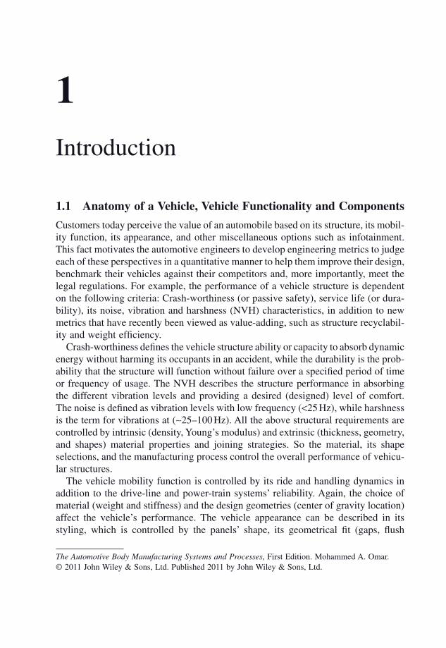
Customers today perceive the value of an automobile based on its structure, its mobil-ity function, its appearance, and other miscellaneous options such as infotainment. This fact motivates the automotive engineers to develop engineering metrics to judge each of these perspectives in a quantitative manner to help them improve their design, benchmark their vehicles against their competitors and, more importantly, meet the legal regulations. For example, the performance of a vehicle structure is dependent on the following criteria: Crash - worthiness (or passive safety), service life (or dura-bility), its noise, vibration and harshness (NVH) characteristics, in addition to new metrics that have recently been viewed as value - adding, such as structure recyclabil-ity and weight effi ciency.
Crash - worthiness defi nes the vehicle structure ability or capacity to absorb dynamic energy without harming its occupants in an accident, while the durability is the prob-ability that the structure will function without failure over a specifi ed period of time or frequency of usage. The NVH describes the structure performance in absorbing the different vibration levels and providing a desired (designed) level of comfort. The noise is defi ned as vibration levels with low frequency ( < 25 Hz), while harshness is the term for vibrations at ( ∼ 25 – 100 Hz). All the above structural requirements are controlled by intrinsic (density, Young ’ s modulus) and extrinsic (thickness, geometry, and shapes) material properties and joining strategies. So the material, its shape selections, and the manufacturing process control the overall performance of vehicu-lar structures.
The vehicle mobility function is controlled by its ride and handling dynamics in addition to the drive - line and power - train systems ’ reliability. Again, the choice of material (weight and stiffness) and the design geometries (center of gravity location) affect the vehicle ’ s performance. The vehicle appearance can be described in its styling, which is controlled by the panels ’ shape, its geometrical fi t (gaps, fl ush
The Automotive Body Manufacturing Systems and Processes, First Edition. Mohammed A. Omar.© 2011 John Wiley & Sons, Ltd. Published 2011 by John Wiley & Sons, Ltd.

2 The Automotive Body Manufacturing Systems and Processes
setting, etc.), and its fi nal paint fi nish. Human visual perception evaluates the vehi-cle ’ s fi nish in terms of specifi c visual qualities: Color properties, encompassing three color attributes, in addition to color matching between the different vehicle parts such as the steel body and the plastic trim. Also, surfaces ’ spatial properties as well as the vehicle ’ s geometric attributes such as gloss, texture, and haze control the customer ’ s perception. For example, if the paint on a vehicle suffers from orange peel, i.e. the paint looks like the peel of an orange, the customer might mistakenly observe this as a defect (variation) in the sheet metal roughness.
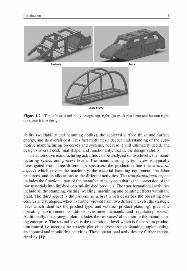
The vehicle ’ s main components and sub - systems can be categorically listed as: Power - train, chassis, exterior and interior trims, and the body in white (BiW) or vehicle body - shell. The power - train is composed of the prime - mover (the internal combustion engine, or electric motor), the gear system, and the propulsion and drive shafts, while the chassis includes the suspension and steering components, in addition to the wheel, tires, and axles. The interior and exterior trims compose the front and rear ends, the door system, and the cockpit trim. Finally, the body in white is made up of the closures (doors, hood, tail - gate) and the frame, see Figure 1.1 ). The frame can be of a uni - body design (Figure 1.2 (a) uni - body), a body - on - frame (Figure 1.2 (b)), or a space - frame (Figure 1.2 (c)). The uni - body design features stamped panels, while the space - frame is made up of extrusions and cast parts. The BiW closures are selected based on the vehicle ’ s constituent material dent - resistance properties (i.e. yield strength) while the frame is designed to provide specifi c torsional and bending stiffness.
1.2 Vehicle Manufacturing: An Overview
After reading Section 1.1 , we can conclude that vehicle performance is judged based on design strength, stiffness, energy absorption, dent resistance, and surface rough-ness. However, before designers select a material or design a specifi c shape, they should consider manufacturability. The manufacturability from an automotive body structure ’ s point of view is described in terms of the design formability, the joining
Figure 1.1 Left: the vehicle body structure without closures, right: the complete vehicle BiW
Introduction 3
ability (weldability and hemming ability), the achieved surface fi nish and surface energy, and its overall cost. This fact motivates a deeper understanding of the auto-motive manufacturing processes and systems, because it will ultimately decide the design ’ s overall cost, fi nal shape, and functionality, that is, the design validity.
The automotive manufacturing activities can be analyzed on two levels: the manu-facturing system and process levels. The manufacturing system view is typically investigated from three different perspectives: the production line (the structural aspect ) which covers the machinery, the material handling equipment, the labor resources, and its allocations to the different activities. The transformational aspect includes the functional part of the manufacturing system that is the conversion of the raw materials into fi nished or semi - fi nished products. The transformational activities include all the stamping, casting, welding, machining and painting efforts within the plant. The third aspect is the procedural aspect which describes the operating pro-cedures and strategies, which is further viewed from two different levels; the strategic level which identifi es the product type, and volume (product planning), given the operating environment conditions (customer demands and regulatory issues). Additionally, the strategic plan includes the resources ’ allocation in the manufactur-ing enterprise. The second level is the operational level which is focused on produc-tion control, i.e. meeting the strategic plan objectives through planning, implementing, and control and monitoring activities. These operational activities are further catego-rized by [1] :
Figure 1.2 Top left: (a) a uni - body design, top, right: (b) truck platform; and bottom right: (c) space - frame design
4 The Automotive Body Manufacturing Systems and Processes
1. aggregate production planning which suggests product plans based on the required product volume, using a generic unit such as the vehicle platform not type, to increase the level of confi dence from the forecast information;
2. production process planning which controls the production techniques to be used, in addition to process routes and sequence;
3. production scheduling to determine an implementation plan for the time schedule for every job in the process route;
4. production implementation which is the execution of the actual production plan according to the time schedule and allocated resources;
5. production control to measure and reduce any deviations from the actual plan and time schedules.
Another important view on the automotive manufacturing systems relates to the information, materials, and value - added (cost) fl ows within the plant. The raw materi-als and supplier parts fl ow from upstream to downstream through the material supply system, the material handling system and fi nally through the material distribution system. However, the information fl ows in the opposite direction, that is from down-stream to upstream, to synchronize the rhythm of production and control its quality; this information fl ow is typically called the pull production system to indicate that the customer side controls the quantity and quality (product type) of the production. On the other hand, the old push system meant that the manufacturing plant outputs vehicles according to a mass production scheme without any feedback from the customer side.
The automobile manufacturing processes are divided into two plants: the assembly plants and the power - train plants. Both of these plants specialize in different transfor-mational processes and convert different raw materials into fi nal parts. However, both are synchronized in time to integrate their fi nal outputs into complete vehicles.
1.2.1 Basics of the Assembly Processes
An automotive assembly plant is responsible for the fabrication of the complete vehicle BiW, starting from a steel and/or aluminum coil and ending with a complete painted car shell. Additionally, the power - train, chassis components, interior and exterior trims are all integrated into the BiW at the end of the assembly process in the fi nal assembly area.
The assembly sequence starts with the receiving area for the coil (which is typi-cally made out of steel and aluminum), which also includes a testing laboratory to check material thickness and surface characteristics. After passing the testing, the coil is either stored or staged for blanking. The blanks are then transferred to the stamping press lines to form the different vehicular panels. A typical BiW consists of about 300 – 400 stamped pieces, however, only a few main panels affect the overall
Introduction 5
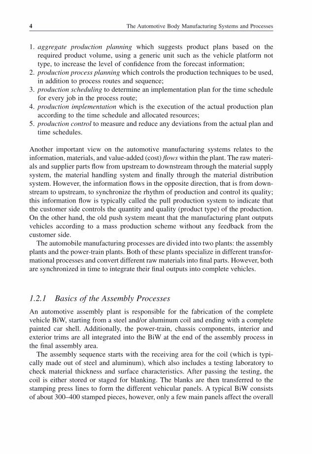
geometry, fi t and fi nish. These panels are the roof, the trunk (inner, outer, and pan), the hood (inner and outer), the under - body, the wheel - house, the body - side, A and B pillars, the fl oor pan, the front module (engine cradle, crush zones, shock towers), the quarter panels, and doors (inner, outer). Some of these panels are displayed in Figure 1.3 .
After the stamping process, some of the panels are joined to create sub - systems in specialized cells, as in the case for the doors where their inners and outers are adhesively bonded, hemmed and spot - welded. Additional cells exist in the stamping area for other components which are then fed to the body - weld or body - shop area. The stamping process utilizes mechanical and hydraulic presses with different tonnage, accessories and dies, so it can handle different panels ranging in shape and size, from 0.1 – 6.5 mm in thickness and with dimensions as small as 1 x panel thick-ness to as large as 500 x panel thickness.
In the body - shop area, the different panels are joined to form the car shell, starting with the under - body and then the body - side (left - and right - hand) outers. The joining of such panels is fi rst done using tack welding to hold the pieces in place, followed by permanent spot welds. A typical vehicle shell has around 5000 spot welds, achieved through robotic welders working in designated cells and programmed offl ine. The completed body shells will also go through a dimensional check process using laser illumination with a charged coupled devices (CCD) camera system to monitor the shell gaps, fl ush setting and fi t. The body - weld also features metal inert gas (MIG) welding for the under - body.
The robotic welding cells are controlled and monitored through separate program-mable logic controllers (PLCs) which are then connected through a main controller to enable the complete line control through a master PLC.
Figure 1.3 The different panels of the vehicle structure
6 The Automotive Body Manufacturing Systems and Processes
The completed BiW is then transferred to the paint - line. The paint booth area cleans the car shells in immersion tanks and applies a conversion coating layer (iron phosphate or zinc phosphate) followed by an electro - coat or e - coat layer. The sub-sequent paint layers require drying or curing, through a combination of convection and radiation - based ovens. Spray paint booths follow the immersion stages, to apply the primer, top coat and clear coat layers. Also the paint booth area features other important steps such as applying the under - body wax and sealants followed by their curing process. Inspection for paint quality in terms of thickness, color match and contaminants is also important in the paint - line. In the paint - line, the vehicles might be taken out of the overall production sequence to create color batches, thus reducing the paint color change time. However, at the end of the line, all vehicles are arranged back in sequence.
After the paint - line, vehicles are transferred to the fi nal assembly area, where the interior (cockpit, seats, etc.) and exterior trims are installed. The fi nal assembly area consists mainly of manual labor using power - tools and fi xtures for the ergonomics, in addition to autonomous carriers that transfer the power - train components (engine, transmission, etc.) for assembly work (installing the cables, fuel hoses, and control-lers) and then to the marriage area. The marriage area is where the power - train is installed in the vehicle body. The fi nal assembly area features a variety of mechanical fastening and riveting operations to install the different trim components in the vehicle shell. Additionally, a variety of sensory systems is used to check the dimen-sional fi t of the different components, in addition to ensuring the proper torque for each joint.
The fi nal step in the assembly process tests the vehicle operation and build, using a chassis dynamometer and a water - test chamber.
The assembly plants require a sophisticated control system that not only monitors the different areas ’ performance (stamping, body - weld, paint and fi nal assembly) but also synchronizes these activities with the reception of parts from the suppliers ’ network and with the power - train facility.
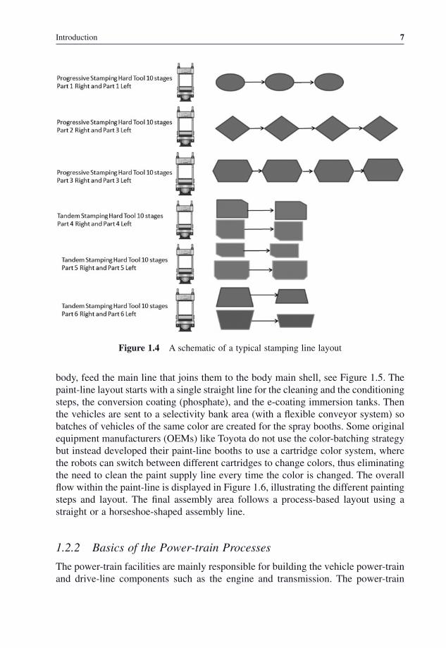
The fl ow of parts and semi - fi nished vehicles within an assembly plant go through different layouts within each assembly area. In the stamping area, the parts are dis-tributed between the different stamping presses depending on the press tonnage and the dies assigned to that press. Also the staging and storing of stamped pieces are done on racks and then transferred to the body - shop or to specialized cells separately, see Figure 1.4 . In other words, the layout in the stamping area is similar to a product - based layout not a process - based one. A product - based layout is similar to the ones found in small workshops or a carpenter shop, where the fl ow of pieces (panels) and equipment allocation (dies) changes according to the product type (vehicle type).
In the body - weld, there is a main assembly line where the sub - assemblies are fed to be joined to the main body frame. So the body - shop layout is a process - based layout, because the focus is on repeating the same process for all product (vehicle) types. The body - weld overall layout is similar to a spine, where the specialized cells that create the door sub - assemblies (joining inner and outer), the hood, the under -
Introduction 7
body, feed the main line that joins them to the body main shell, see Figure 1.5 . The paint - line layout starts with a single straight line for the cleaning and the conditioning steps, the conversion coating (phosphate), and the e - coating immersion tanks. Then the vehicles are sent to a selectivity bank area (with a fl exible conveyor system) so batches of vehicles of the same color are created for the spray booths. Some original equipment manufacturers (OEMs) like Toyota do not use the color - batching strategy but instead developed their paint - line booths to use a cartridge color system, where the robots can switch between different cartridges to change colors, thus eliminating the need to clean the paint supply line every time the color is changed. The overall fl ow within the paint - line is displayed in Figure 1.6 , illustrating the different painting steps and layout. The fi nal assembly area follows a process - based layout using a straight or a horseshoe - shaped assembly line.
1.2.2 Basics of the Power - train Processes
The power - train facilities are mainly responsible for building the vehicle power - train and drive - line components such as the engine and transmission. The power - train
Figure 1.4 A schematic of a typical stamping line layout

8 The Automotive Body Manufacturing Systems and Processes
plants feature different transformational manufacturing processes from those found in the assembly plants. The power - train plants use a variety of forging, casting and machining operations to fabricate the engine components and the transmission. For example, the engine cylinder blocks are made of cast iron or are cast out of aluminum or in some cases from aluminum with a magnesium core to reduce the total weight of the engine. After the entire engine and the transmission components have been manufactured, they are assembled manually. For example, after casting and machin-ing the engine cylinder block and the exhaust manifold, forging the pistons and the crankshaft, and fi nishing the valves, the crankshaft is installed manually in the cyl-inder block and secured by the bearing caps, which are torqued automatically. Then the pistons are lubricated and installed in the cylinder block carefully to prevent scratching the cylinder lining. Then the cylinder head is mounted and torqued to hold
Figure 1.5 The layout of a body - weld line
Side outer right
Side outer left
Engine Compartment
Rear Floor a
ssembly
Floor asse
mbly
Roof Cowl
Figure 1.6 The basic processes in an automotive paint - line
Introduction 9
the valves assembly. The inlet and exhaust manifolds are installed next and fastened mechanically. The testing of the engine operation is done next, using an engine dynamometer.
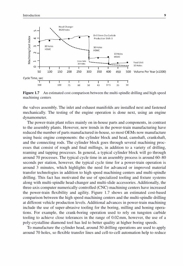
The power - train plant relies mainly on in - house parts and components, in contrast to the assembly plants. However, new trends in the power - train manufacturing have reduced the number of parts manufactured in - house, so most OEMs now manufacture using basic engine components: the cylinder block and head, camshaft, crankshaft, and the connecting rods. The cylinder block goes through several machining proc-esses that consist of rough and fi nal millings, in addition to a variety of drilling, reaming and tapping processes. In general, a typical cylinder block will go through around 70 processes. The typical cycle time in an assembly process is around 60 – 80 seconds per station, however, the typical cycle time for a power - train operation is around 3 minutes, which highlights the need for advanced or improved material transfer technologies in addition to high speed machining centers and multi - spindle drilling. This fact has motivated the use of specialized tooling and fi xture systems along with multi - spindle head - changer and multi - slide accessories. Additionally, the three - axis computer numerically controlled (CNC) machining centers have increased the power - train fl exibility and agility. Figure 1.7 shows an estimated cost - based comparison between the high speed machining centers and the multi - spindle drilling at different vehicle production levels. Additional advances in power - train machining include the use of super - abrasive tooling for the boring, milling and honing opera-tions. For example, the crank - boring operation used to rely on tungsten carbide tooling to achieve close tolerances in the range of 0.02 mm, however, the use of a poly - crystalline diamond tool has led to better quality at higher boring speeds.
To manufacture the cylinder head, around 50 drilling operations are used to apply around 70 holes, so fl exible transfer lines and cell - to - cell automation help to reduce
Figure 1.7 An estimated cost comparison between the multi - spindle drilling and high speed machining centers
10 The Automotive Body Manufacturing Systems and Processes
the cycle time. Other specialized operations like the cam boring include the use of a long - line boring bar with custom fi xture, to lower or raise the cam. On the other hand, to manufacture the crankshaft, the OEMs have to apply a series of different operations with tight tolerances, that include balancing the mass of the forged steel material, turning of both edges for clamping, and turning for the main and pin bear-ings, drilling the oil holes, fi nish grinding for the main and pin bearings, then super-fi nish the main and pin bearings. Finally, the crankshaft is washed, balanced and inspected. The balancing is done using an intelligent fi xture that rotates the shaft and compensates for any imbalances by drilling holes.
The camshaft follows a similar processing sequence to that of the crankshaft, with changes in the tooling used and with the addition of a hardening process, where the shaft is heated using induction coils, then cooled rapidly.
The power - train manufacturing processes are also responsible for making the transmission components, mainly the gear system. The typical material for the dif-ferent automotive gears is based on alloyed steel that provides the hard fi nish for the gear teeth while the core is soft and tough, so that it resists continuous use in terms of fatigue and wear resistances. These requirements motivate the use of different heat treatment steps to achieve the hard teeth and ductile core, which include a carburizing step to increase the carbon content within a controlled depth within the gear surface, a quenching process to increase the hardness, and a tempering step to improve the core toughness.
The basic operation used to form the gear is based on hot forging, followed by variety of hobbing and shaping cutting steps to generate the gear teeth. In the shaping process, a cutting gear with the designed profi le is used to generate a similar tooth profi le in the blank gear, however, in the hobbing process, a worm - like cutter cuts teeth on a cylindrical blank to generate the teeth, hence the hobbing process cannot be used to generate internal gears. Other subsequent operations include gear shaving,
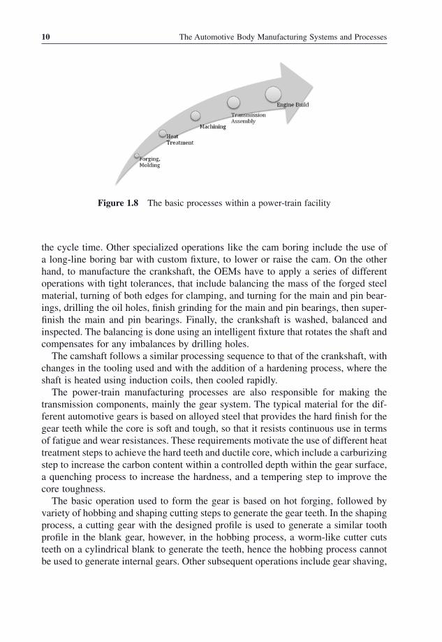
Figure 1.8 The basic processes within a power - train facility

Introduction 11
where a helical gear - like cutter, with closely spaced grooves, meshes with the gear so that a controlled material is removed from the gear teeth surfaces.
The standard processes within a power - train facility are displayed in Figure 1.8 . So, the overall functional look of the vehicle manufacturing processes can be shown in Figure 1.9 .
1.3 Conclusion
The automotive manufacturing processes (assembly and power - train) play a major role in deciding on the vehicles ’ design characteristics and the overall cost. Thus it is very important for designers and engineers to understand the current manufacturing infrastructure available in their company ’ s production lines. This will pinpoint the manufacturing capabilities and limitations. At the end of the day, the designer will specify the design tolerances but the machine will control the achieved tolerances. Additionally, designers should consider the materials ’ compatibility from the joining process welding point of view, to avoid galvanic corrosion issues.
Additionally, designers should be aware that the vehicle design complexity in terms of number of parts and intricate shapes results in additional manufacturing steps (added cost and processing time). Also, the number of robotic welders and stamping presses should be taken into account due to their direct impact on the pro-duction rate. However, one should recognize that different OEMs make their deci-sions with regard to the vehicle type, volume and design based on their business models, which might be based on one of the following;
1. competing based on differentiation; 2. competing based on cost; or 3. competing based on time to market.
Figure 1.9 The basic processes in an automotive assembly plan
12 The Automotive Body Manufacturing Systems and Processes
A company competing based on different and distinguished vehicle types might add complications to their manufacturing systems to achieve new added features or provide a wide range of options. However, an OEM competing on cost aims to reduce the manufacturing cost through less complicated designs and options. The OEMs who compete based on response time typically utilize common components and designs shared between different vehicle types and between old and new models of the same vehicle type. For example, the engine cradle design can be shared between old and new models without affecting the customer ’ s perception of the vehicle as a new model, at the same time it helps the OEM to cut the development time and cost, in addition to reducing the set - up changes in the manufacturing plants.
Additionally, recent changes in the automotive market have forced the automotive OEMs to increase their product portfolio to accommodate new demands from emerg-ing markets, mainly in Brazil, Russia, India, and China or the BRIC countries. This increase in vehicle models has shifted the OEMs ’ manufacturing models from the economy of scale to an economy of scope , which motivates further understanding of the manufacturing environment because such a shift adds complications in the fol-lowing areas: the sequencing of the different models, the production capacity fore-casting, and parts (suppliers) and sub - systems ’ diversity. So new manufacturing and design strategies should be implemented and explored to alleviate some of these challenges such as the use of modular systems and subsystems between the different models, which reduce the parts ’ diversity and the variations within the processes. At the same time, the modularity might have negative impact on the OEMs ’ overall fl exibility [2] .
The impact of the above challenges on the automotive industry have led the auto-motive OEMs to revise their production and business strategies through mergers with other OEMs and by implementing effi cient manufacturing procedures such as lean manufacturing and its different derivatives and versions created to suit each company style and product type. The number of automotive OEMs has dropped from 36 in 1970, to 21 in 1990, and to 14 in 2000. However, the number of automobiles pro-duced is around 55 million vehicles [3] with the majority of production taking place in Asia (around 18 million vehicles), followed by Western Europe (17 million vehicles) and then the USA (around 11.5 million vehicles).
Exercises
Problem 1
In your own words, describe the current metrics used to judge the automobiles, by a typical customer and by an automotive engineer.
Problem 2
What is the difference between the noise and vibration within the context of the automotive NVH requirement?
Problem 3
Explain the three manufacturing system perspectives.
Problem 4
What is the difference between the operational and strategic operations, within the procedural aspect?
Problem 5
List the basic manufacturing processes involved in the making of the automobile BiW, and comment on each process layout and drivers.
Problem 6
List the main differences between the automotive power - train and assembly proc-esses, from the following perspectives: the dependence on suppliers ’ parts, and the nature of the processes utilized.

14 The Automotive Body Manufacturing Systems and Processes
Problem 7
What is the difference between the gear hobbing and shaping processes?
Problem 8
What is the impact of economy of scale and the economy of scope on the automotive manufacturing process?
Problem 9
Automotive OEMs might compete based on different criteria, what are they?
Problem 10
List three challenges that have impacted the automotive industry in the past decade.
The Automotive Body Manufacturing Systems and Processes, First Edition. Mohammed A. Omar.© 2011 John Wiley & Sons, Ltd. Published 2011 by John Wiley & Sons, Ltd.
2
Stamping and Metal Forming Processes
The formability of sheet metals is one of the most important steps in the automobile manufacturing activities, because it is the decisive factor in the vehicle shell shape (styling), geometry (fi t and fi nish), and performance (wind noise, water leakage). Additionally, the development and approval of the stamping dies are the most expen-sive and time - consuming efforts during a new vehicle design and launch. The die approval process can consume about 50 weeks before the Start of Production (SoP) to achieve the fi nal dimensional validation.
The stamping of sheet metals can be defi ned as the process of changing the shape of the sheet metal blank into a useful shape in the plastic deformation state, using a die and a mechanical press; stamping is considered a net shaping process. However, the stamping engineering efforts are not limited to production engineering (i.e. the stamping process) but also include the development of the required tooling (i.e. stamping engineering). Such tooling includes the die making in addition to the fi x-tures and the automation tools such as the transfer mechanisms typically equipped with suction or electromagnetic cups. For the die making process, stamping engineer-ing starts with the desired panel shape provided by the designer in a CAD fi le, in addition to the sought panel mechanical properties such as dent resistance (i.e. yield strength). Then, the engineers start with the material selection, i.e. selecting the steel grade, thickness and heat - treatment from what is typically provided by the steel mill. Feasibility analyses follow for each selected material, which lead to a process plan (process settings). After that, the die surface design starts with Finite Element (FE) simulation and numerical trials, followed by the actual (experimental) testing. Successful die designs will then be constructed and validated through a series of try - outs in the die - maker facility and then at the stamping line, using different number of parts (prototypes) and dimensional validation strategies (functional build, event -

16 The Automotive Body Manufacturing Systems and Processes
functional build). Finally, the automation and auxiliary tooling are constructed for each approved die for series production.
On the other hand, the stamping process starts with the steel and aluminum coils provided by the mills with specifi c thickness, surface topography, widths, and heat treatments. Additional inputs to the stamping press are: the die (toggle, progressive), the lubricants (water or oil), the tonnage conditions, and other process settings such as clearances. Generally, the stamping process constitute following main operations; blanking (or blank preparation), stamping (forming), and assembling activities.
A typical material fl ow in the stamping area is shown in Figure 2.1 . The sequence in Figure 2.1 describes the following main operations:
1. Blank preparation: involves a cutting action about a closed shape that is the piece retained for future forming (i.e. the blank). The blank shape is composed of any number of straight and curved line segments. A more detailed look at blanking shows that it is further composed of slitting and shearing. Slitting is the process of cutting of lengths (usually coils) of sheet metal into narrower lengths by means of one or more pairs of circular knives. This operation often precedes shearing or blanking and is used to produce exact blank or nesting widths. Shearing is done by a blade acting along a straight line. The sheet metal is placed between a sta-tionary lower blade and a movable upper blade and is sheared by bringing the blades in contact.
Figure 2.1 The sequence and basic steps in the stamping line

Stamping and Metal Forming Processes 17
Other cutting operations exist in the automotive stamping for developed blanks, such processes include: (1) piercing which is the forming of a hole in sheet metal with a pointed punch without metal fallout; (2) lancing that creates an opening without completely separating the cut piece from the body of the sheet metal, such as the case for louvers; (3) trimming is the process of removing unwanted metal from the fi nished piece that was required for some previous stamping operation, such as binder areas, or was generated by a previous stamp-ing operation, such as the earing zone on the top of a deep drawn cup; and (4) parting operations are used to separate two identical or mirror image stamp-ings that were formed together (typically for the expediency of making two parts at one time or to balance the draw operation of a nonsymmetrical part). Parting also is an operation that involves two cut - off operations to produce contoured blanks from strip.
2. First forming operations: which aim at forming the blank into a semi - developed blank that has the initial shape. First forming operations include bending and fl anging through either a shrink fl anging, where the length of the fl ange shrinks as it is formed, or stretch fl anging where the material is stretched as it is fl anged.
3. Drawing operations: in the automotive press shop, most dies are called draw dies because the metal is drawn into the die cavity. However, most of the deformation modes are based on biaxial stretch over the punch or a bend - and - straighten from the fl ange. Drawing, sometimes known as cup drawing, radial drawing, or deep drawing, has a very specifi c set of conditions which differentiate it from other operations. The unique attribute of deep drawing is the deformation state of the fl ange. As the blank is pulled toward the die line, its circumference must be reduced. This reduction in the circumference generates a compressive stress in the circumferential direction, resulting in a radial elongation as the metal is extruded in the opposite direction.
4. Subsequent operations: most of the automotive panels require a sequence of forming steps because the degree of forming (fl ange angle, etc.) cannot be accom-plished in a single step. Such operations include the re - strike step which comes after the metal has been stretched over a large radius punch (to avoid splitting), to spread the metal into the desired shape without any additional tension in the stamping line. Another typical subsequent forming operation is the redrawing. Limits are imposed on the blank diameter which can be drawn into a cup of a given diameter (this will be discussed in further detail in Section 2.1.3 ). Should a deeper cup be required, an intermediate diameter cup is drawn fi rst; then the cup is redrawn in one or more subsequent stages to achieve the fi nal diameter and height.
5. Assembling activities: these include variety of specialized cells for combining panels to form BiW components such as joining the door inners and outers. Additionally, other assembling might be done in die - joining strategies.