Embed Size (px)
Citation preview

TheAuto-ReturningRemoteControlBoatGroup#47
SomakGhosh
ZainZaman
GrantEverett
TA:VigneshSridhar

1
TableofContents
1Introduction1.1Objective1.2Background1.3HighLevelRequirementsList
22223
2Design2.1BlockDiagram2.2HighLevelFunctionOverview2.3PowerUnit2.3.1Batteries2.3.2LowVoltageDetectorCircuit2.3.3VoltageRegulator2.4ControlUnit2.4.1.Microcontroller2.4.2PowerControlLogic2.5SignalUnit2.5.1Overview2.5.2RelativeSignalStrengthIndicatorCircuit2.5.3SchmittTrigger2.5.4Sensor2.5.5AntennaArray
334446
10111115181819232526
3ToleranceAnalysis 264Cost 275Schedule 286EthicsandSafety 297References 318Appendix 33

2
1Introduction
1.1 ObjectiveProfessorOelzepresentedwhatseemedtobeaverystraightforwardproblemwithamodelboatofhistotheECE445class.Hesailsthisremotecontrolboatonalakeandwhilethefunctionalityworkswell,whentheboatrunsoutofbatteryorthesignalfromtheremotecontrolbecomestooweak,hemustphysicallyretrievetheboatfromthelake.Inordertotackletheproblemathandwewillhavetocreateseveraldifferentmoduleswhichwillworktoensurethattheboatwillreturntoitsdesignatedhomelocation.Wewillhavetocreateabatterymanagementsystem.Thiswillbedonebymakingalowvoltagedetectorcircuitwhichwillactwhenthebatterysupplyislowandwillbeusedtoguidetheboatbacktoshore.Thenextkeymodulewillbethesignalstrengthdetector.Thiscomponentwilldetectwhentheboatisinalowsignalrangeandclosetohavingnosignal.Thegoalofthismodulewillbetostoptheboatandreturnalocationwithstrongersignalandwithinasaferange.Itwillbeguidedbyanantennaarrayandasignaldetectioncircuit.Wealsoplantoimplementcontroltotheboat.Thiscontrollerwilltakesignalfromvarioussensorsontheboatanditwillsteertheboatandpowerthemotor.Allofthesecomponentswillbecomplementedandcontrolledamicrocontroller.Thisisahighleveldescriptionofthesolution.Eachtechnicalcomponentwillbediscussedinmuchfurtherdetailbelow.
1.2 BackgroundThisprojectwasmotivatedfromareal-worldissueandcanbeappliedtoallchildren’sproducts.Manyoftheremotecontrolproductsarevery“low-tech”andhaveverylittlefail-safeoptionsforusewhentheconditionsarenotideal.Whentheyareusedbychildrentheyaredestroyedafterveryfewuses.Thisdoesverylittletojustifythecostsoftheseproducts.However,webelievethatwithsomeupgradesthesetypesofproductscannotonlylastmuchlonger,butalsobemuchmoreenjoyablewhenused.
Thistechnologyhasseveralotherpotentialapplications.Itcouldbeaveryusefuladditiontodronetechnologyduringwartimeandfordeliveringsuppliessafelyandreliably.Withtheincreasedreliabilityandrobustnessthatourdesignwouldhavedronescouldbeusedinmorelocationswithlesspowerandmorereliability.Inareaswhererechargesandlargebatterypacksarenotaccessiblethistechnologycouldhavemanyapplications.
3
1.3 HighLevelRequirementsList1. Requirement1isthattheboatmustbeabletodetectwhenithasbelowtherequiredbattery
level(subjecttofurthertesting,approximately4.8V)andhaveenoughreservestoreturnhome.
2. Requirement2isthattheboatmustbeabletodetectwhentheReceivedSignalStrengthIndicator(RSSI)isbelowadequatelevelsandbeabletoreachastrongersignalpointorreturnhome.
3. Requirement3isthatboatwillconsistentlyreceivecorrectsignalsfortheangleanddirectionaswellguideitselfbackintoaregionofsafetywithintherequiredRSSI.
2 Design
2.1BlockDiagram
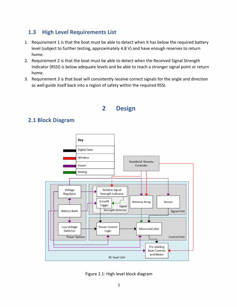
Figure2.1:Highlevelblockdiagram

4
2.2 High-LevelFunctionalOverview&PhysicalDesignTheblockdiagramdesignconsistsoffourprimaryunits:TheHandheldRemoteControl,theSignalUnit,theControlUnit,andthePowerUnit.TheHandheldRemoteControlcommunicatesdirectlywiththeSignalUnitviaIRsignalstodeterminethelocation,route,andthe‘homedestination’.TheSignalUnitconsistsofanRSSI(RelativeSignalStrengthIndicator)modulewhichmeasurestherelativesignalstrengthfromtheuser.TheControlUnit,whichcontrolsthemotorandrudder,usesdatareceivedfromthePowerSystemandtheSignalunittoevaluateiftheboatneedstoreturnhomeortoaregionwithintheRSSIrequirements.Inadditiontopoweringtheboat,thepowersystemincludesacircuitthatdetectswhenthebatterylevelisonlyhighenoughtomanageaone-waytripbackhome.(HomeisdefinedasalocationwheretheRSSIsignalstrengthisthemaximum).
Forourphysicaldesigntheintegrityandshapeoftheboatwillbekeptintact.Theboatwaspreviouslysealedwhichweopenedtoaddallofourelectricalcomponentsinordertointegratewiththeexistinghardware.Tomitigateallsafetyconcernswecanuseasimilargradeepoxytosealtheboat.Thephysicalshapewouldbeleftintactwithsomeaddedweightandallsafetyconcernswouldbesolvedbyusingtheepoxytowaterprooftheboat.Theperformanceoftheboatshouldnotbeaffectedfromtheadditionswearemakingandfromtheoutsidetheboatshouldlookexactlythesame.
2.3 PowerUnit
2.3.1BatteriesParts:(6x)DuracellAAAlkalineBatteries1.5VMN1500(LR6)
Theboatispoweredby6AA,1.5Vbatteriesaddinguptoproduceatotalof9V.Typically,mostAAbatteriessharesimilarcharacteristics.Inthisthisproject,theDuracellMN1500wasused.Table3.1belowstatestheproductspecificationswhileFigure3.1representsthetypicalchargecharacteristics.

5
Table3.1:Batteryspecifications[1]NominalVoltage 1.5VOperatingVoltage 1.6-0.75V
Impedance 120m-ohmat1kHzTypicalWeight 24gm(0.8oz.)TypicalVolume 8.4cm3(0.5in.3)
Terminals FlatStorageTemperatureRange -20°to35°(Celsius)OperatingTemperatureRange -20°to54°(Celsius)
-4°to130°(Fahrenheit)ANSI 15AIEC LR6
Figure3.1:Batterydischargecurveat21°C(70°F)[1]

6
2.3.2LowVoltageDetectorCircuit
Parts:MMSZ4681T1GZenerDiode,(3x)1MWResistor,100kWResistor,TexasInstrumentsTL331
Thelowvoltagedetectorcircuitwillmonitorinputfromthebatteriesandcommunicatewiththecontrolunittoindicatewhenthereisonlyenoughpowerleftfortheboattoreturntothehomelocation.AccordingtoTable3.1,theoperatingvoltageforthebatteryinusehasalowerlimitof0.75V.Sincewehavesixofthosebatteries,thelowestvoltagelevelbeforethebatteriesareineffectiveis4.5V.Asaresult,thevoltagelevelatwhichthecircuitsignalsthecontrolunittoforcetheboatbackhomeshouldbeatavaluegreaterthan4.5V.Henceforth,thisvoltagewillbereferredtoastheindicationvoltage.
Totestfortheindicationvoltage,wewillfirstmeasurethevoltageofthebattery.Next,wewillphysicallysettheboatonabodyofwaterandhaveitcompletearound-tripfromtheusertoitsmaximumrange.Upontheboat’sreturn,thevoltageofthebatterieswillbere-measured.Sincethebatterylevelconsumedwouldrepresenttwofull-rangetripsoftheboat,thetotalbatterylevelconsumedwillbedividedby2.Thetestwillbeperformedthriceandtheaveragevalueswillbetakentoensureaccuracy.Finally,theresultantvoltageconsumedwouldbeaddedtotheminimumoperatingvoltageof4.5Vtoobtaintheindicationvoltage.
Althoughnophysicaltestshavebeenperformed,acutoffvalueof4.8Vfortheindicationvoltageshouldbefeasibletheoretically.Thisisbasedofftheassumptionthata6.67%chargeshouldbeallthatisrequiredforaone-waytripbacktothehomelocation.However,sincethisassumptionisnotbackedbyfactualinformation,arangeofvaluesrelatingthebatterylevelandindicationvoltageisshownintable3.2.
𝑉#$%#&'(#)$ = 4.5𝑥100 + 4.5
𝑥:percentageofbatterylevelrequired
Table3.2:BatterylevelrequiredvsindicationvoltageBatteryLevelRequired(%)
IndicationVoltage(V)
5 4.7257 4.81510 4.9512 5.0415 5.175
Figure3.2showsaschematicofthelowvoltagedetectorcircuitgeneratedonEagle.ThecircuitusesasingledifferentialcomparatorintegratedintheTexasInstrumentTL331chip[2].Thechiptakesintwoinputsanddependingonwhichoneofthevaluesishigher,outputsadigital

7
HIGHorLOW.ItisoriginallyconfiguredtooutputaHIGHwhenVin+isgreaterthanVin
-,andalowwhenotherwise.Ourprojectdemandsthatthelowvoltagedetectorcircuit,outputsahighwhenevertheindicationvoltageisreached.Therefore,thecircuitusedisaninvertingcomparatorcircuitwherethebatteryisconnectedtothenegativeterminal,Vin
-whichistobeusedasthereferencevoltage.Thepositiveterminal,Vin
+receivesthevoltageacrosstheZenerdiodeastheinput.TheZenerdiodeisusedtoregulatethevoltage.Therefore,evenwitha9Vinput,a2.4VZenerwouldhaveavoltageofapproximately2.4V+/-5%goingintoVin
+.WeconnecttheVCCpinsuchthatittakesinthevoltagedirectlyfromthebattery.Asthevoltagekeepsreducing,theinputvaluesofVin
+andVin-convergeuntilVin
+exceedsVin-whichmeansthat
theindicationvoltagehasbeenreached.Thisaccordingtooursimulationresults,tendstohappenaroundtheloweredgeZenervoltageofthediodeused.
Figure3.2:Eagleschematicofthelowvoltagedetectioncircuit
Table3.3:ZenerDiodespecifications[3]Circuit
SchematicSymbol
Device Marking ZenerVoltage LeakageCurrent
VZ(Volts) @IZT IR@VRMin Nom Max µA µA Volts
D2 MMSZ4681T1G CF 2.28 2.4 2.52 50 2 1D1 MMSZ4684T1G CK 3.13 3.3 3.47 50 7.5 1.5

8
ResistancefordiodesD1andD2:(Equation1)
𝑅FG =𝑉H#$𝐼FJ
=4.5
50×10LM = 90kW
MaxinputcurrentintoD1andD2:(Equation2)
𝐼F =𝑉H'P𝑅FG
=9
100×10LQ = 90µA
Usingequations1and2andrelatingthesolveddatatotheZenerdiodespecifications[3],resultedinthe100kWbeingchosentobeconnectedtothediodesD1andD2.
Table3.3representsthespecificationsoftheZenerdiodesused.ThecircuitusesavoltagedividerattheVin
-terminaltodividetheincomingbatteryvoltageby2.ThismeansthatthemaximuminputvoltagefedintoVin
-is4.5V.Vin+,ontheotherhand,staysataconstant2.4V
(+/-5%)duetothevoltageregulationcharacteristicofD2.Testresultsofthecircuitsimulationareshownintable3.4andfigure3.3.
Table3.4:LowVoltageDetectorCircuitSimulationOutput
BatteryVoltage(V)
Vin-(V) Vin
+(V) Output
9 4.5 2.4 LOW8 4 2.4 LOW7 3.5 2.4 LOW6 3 2.4 LOW5 2.5 2.4 LOW4.8 2.4 2.4 HIGH4.75 2.375 2.4 HIGH

9
Figure3.3LowVoltageDetectorCircuitSimulationOutput
Basedontable3.4,itcanbeseenthatassoonastheindicationvoltageisreached,thecomparatoroutputsalogicHIGHtothecontrolunittoindicatethatthebatterylevelislow.Thecontrolunitthenproceedstodeterminetheboat’snecessarycourseofaction.TheLOWcorrespondstoavoltageof0,whiletheHIGHwillbeequaltothebatteryvoltageascanbeseeninfigure3.2.Figure3.3usesaconsistentoutputvoltageof3.3Vtomakethegrapheasiertointerpretandunderstand.Inreallifeexperimentation,thevoltagewillrangefrom4.5to9V.Sincetheinputthatthecontrolunitreceivesisadigitallogicinput,thevalueofthevoltageitselfwillnotmatter(allvoltagesrangingfrom4.5Vto9VwillresultinthesameoutputofaHIGH);unlessitis0orveryclosewhichwillcorrespondtoaLOW.
Thesimulationresultsareperfectsincetheydonotaccountforthenon-idealityofthedevicesused.Therefore,anexactvaluedecimalvalueof2.4VshouldnotbeexpectedfromtheZenerneithershoulditbeassumedthatthebatterysuppliesexactvaluessuchas9.0oran8.0.Moreover,itisalsoimportanttomentionthattheresistanceswouldhaveanin-builtpercenterrorofaround+/-5%.However,theseirregularitiesanderrorswillbeabletobedealtwithbestonlyduringthebuildprocess.
Table3.2indicatesarangeof4.725to5.175Vfortheindicationvoltage.Thecircuititself,canbeconfiguredtomatchthevalueobtainedexperimentally.ThiswillbedonebychoosingdifferentvaluesfortheZenerdiodes,D1andD2.

10
Requirements Verifications
1. TheTL331shouldoutputalogicalHIGHinsteadofLOWwhenthebatteryvoltagedropsbeloworequals4.8V(+/-5%)
1. Useadcpowersupplytopowerthecircuitandthenusetheoscilloscopetodetectif:
A. aHIGHoutputisgeneratedwhenthevoltageacrossR1,1MWislessthanorequalto4.8V(+/-5%)(figure3.2)
2.3.3VoltageRegulatorParts:STMicroelectronicsL4931,2.2uFCapacitor(x2)
ThevoltageregulatorwillbeusedtosupplyaconstantvoltagetothecontrolunitandtheRSSI(RelativeSignalStrengthIndicator)circuitthatadherestotheirinputrequirement.Inthiscasetheinputvoltagerequiredwas3.3V,thereforetheSTMicroelectronicsL4931waschosen.TheL4931isalinearvoltageregulatoroutputs3.3Vforanyvalueinourbattery’soperatingrange(4.5V-9V)[6].Figure3.4displaysthecircuitschematic.
Figure3.4:L4931CircuitSchematic[6]
Requirement Verification1. Outputavoltageof3.3V(+/-5%)intoVCC
whenthebatteryvoltageisgreaterthan4V(+/-5%)
1. Useamulti-metertomeasurethevoltageacrossD1andverifythatitis3.3V(+/-5%)wheneverthebatteryvoltageisgreater4V

11
2.4 ControlUnit
2.4.1MicrocontrollerPart:ATmega328P
Themicrocontrolleristheprimarycomponentofthecontrolunit.ThemicrocontrollerwilltakeinputsfromtheRFreceiversandsensor.Thiswillbean8-bitmicrocontrollertoproperlyexecutethecomputationrequiredforourBang-BangControlLoop.Whilethiscouldbedoneona4-bitmicrocontroller,thesensorweusehasan8-bitresolution[7].
ThemicrocontrollerwilltakeaninterruptfromthePowerControlLogic.Whenthisinterruptistriggered,wewilldisablesleepmode.Wewillalsocheckthevalueofthiswheneverwecompleteanentirecontrollooptoseeifweneedtoreactivatesleepmode.Wereactivesleepmodewhenwewanttoallowtheusertocontroltheboat.Figure4.1isablockdiagramshowingtheinputsandoutputstothemicrocontroller.Itwilltakeananaloginputfromtheantennaarray,andadigitalinputfromthemagnetometer.Finally,itwilloutputaPulseWidthModulator(PWM)totheESC(ElectronicSpeedControl).
Figure4.1:Microcontrollerinputandoutputhardwarecomponents
Ourcodewillbeoptimizedbasedonwhetherornotwehavereaddatafromthemagnetometer,sincethatisthebottleneckintermsoffrequency.Thetwopossiblestates,SerialandJump,arechangedduringtheReadDataandChangeStates.ThisisdonetooptimizeournumberofInstructionsPerSecond.TheReadRFsensorandSave,CalculateDesiredDirection,CalculateOurDirectionblockswillalloperatewithawrapper.Uponcompletionofthisblock,thiswrapperwilldecideifweexecutethenextblockorifwePollMagnetometeragain.IfweareintheSerialExecutionstate,wewillsimplyexecutethenextcalculation.IfweareinJumpExecutionstate,thewrapperwillsaveavaluecorrespondingtothenextrequired

12
block,thenPolltheMagnetometer.WhenwegettotheJumptoNextNon-ExecutedBlock,wewilljumptothefunctionassociatedwiththesavedvalue.Theflowchartforthecodeisdepictedinfigure4.2.
Figure4.2:Flowchartforthemicrocontrollercode
RequiredNextmeansthatwecontinuetothatinstructionregardlessofstate.Forconditionalblocks,wealsorequiretheBooleanoutputtobeequivalent.SerialExecutionmeansthatwefollowthegreentransitions,providedweareintheSerialExecutionstate.JumpExecutionmeansthatwefollowthebluetransitions,providedweareintheJumpExecutionstate.Thesestatesarepartofthesoftware.

13
WehavechosentheATmega328Pasthemicrocontrollerforthisprojectforavarietyofreasons.Mainlybecauseitisalowcost[5],readilyavailable8-bitmicrocontroller.Italsosatisfiesalltherequirementsofhavinginterruptpins,PWMoutputandsupportsoperationat3.3V[4].Additionally,thecurrentat1MHzfrequencyand3.3Vis0.92mA,whichyieldslowpowerconsumption[8].Atthisspeed,wecanperform12,500instructionsbeforethemagnetometerhasdatareadytoread.Thecalculationbelowverifiestheclaim.
1000000𝐼𝑃𝑆80𝐻𝑍 = 12500𝐼𝑛𝑠𝑡𝑟𝑢𝑐𝑡𝑖𝑜𝑛𝑠
IPS=InstructionsPerSecondorInstructiontimesHertz
Requirements Verification1. DesiredSleepModefunctionsas
expected:a. ExitsleepmodewhenPCLis
logicalHIGH2. EntersleepmodewhenPCLislogical
LOW
1. SimulateaPCLHIGHvaluewhenmicrocontrollerisinsleepmode,ensuremicrocontrollerwakesup
2. SimulateaPCLLOWvaluewhenmicrocontrollerisinsleepmode,ensuremicrocontrollerdoesnotwakeup
3. SimulateaPCLLOWvaluewhenthemicrocontrollerisnotinsleepmode,ensurethemicrocontrollerenterssleepmodeafterthecurrentcontrolloophasfinished
2. DrivePWMsuchthatthefrequencyandamplituderepresenttheanglechangeweneedtomake
2. Givenoutputs(phase,speed)fromtheBang-Bangcontroller,ensurethePWMhasthecorrectdutycycle,frequencyandamplitudeasdescribedinthePWMRequirementsandVerifications.Theseoutputswillbeanangle,andthisangleisthedifferenceindirectionweneedtotake.
WewillimplementaBang-BangController,PulseWidthModulator,andconnecttoanElectronicSpeedControlleronthemicrocontroller.
Controller
Forthecontroller,wewillbeusingBang-BangControl.Thistypeofcontrollerisusedbecausewehaveabinaryinputwhichwillonlyneedtohave2-fixedpositionstoswitchbetween.The

14
motorwilleitherbeonoroffandwillsteerinadirectionbaseduponthesignalreceivedfromthePulse-WidthModulator.
Requirements Verifications1. Theboathas2behaviors-
A. themotorisonwhentheboathasbothsufficientpowerandsignal
B. whenboathaseitherlowbatteryorlowsignalthemotorwillshutoffandwaitforinstructionsforcorrectdirectiontotravelin.
1. Testthebehaviorofthecontrolsystem(simulatedusingSimulinkonMATLAB)onamotorforrequirements
2. Inputa0formotorspeedandensurethatthemotorisnotrunning.
3. Inputaspeedgreaterthan0tothemotorandensurethatthemotorisrunning.
2. Theboat’sElectronicSpeedControlcansuccessfullyreceivecorrectpulseinformation-
A. thepulseamplitudewillencodethespeedwithin(+/-5%error)
B. thepulsephasewillencodetheanglewithin(+/-5%)
2. TestthebehaviorofthecontrolsystemusingSimulinkandthemicrocontroller.InputadesiredangleandspeedtothemicrocontrollerandverifyifthePulseWidthModulatorissendingthecorrectdirectiontotheelectronicspeedcontrolandthemotor.Thisbehaviorcanbesimulatedandthedatawillbereturnedinthesamescript.
PulseWidthModulator(PWM)
Part:WewilluseaPWMimplementedonthemicrocontrolleritself.
ThepurposeofthePWMwillbetosendinformationtotheelectronicspeedcontroller.ThePWMwillsendamessagesignaltotheelectronicspeedcontrollercontaininginformationonthedesiredpoweroutputtothemotorandthenecessarydirectionoftraveltore-enterastrongersignalrangeorreturntoshorebecauseoflowbattery.Theencodedmessagewillcontinueboththespeedandanglethattheboatwillneedtotravelin.Thespeedistheamplitudeofthepulseandtheangleisthephaseofthepulse.ThePWMwillsendasignalevery2-3millisecondsandwilloperateatafrequencytomatchtheElectronicSpeedControl(ESC).WewillpurchaseaPWMcompatiblewiththeESCwehavechosen.
15
Requirement Verification1. ThePWMshouldworkat1kHzto
matchtheelectronicspeedcontrol1. Usevariousdutycyclesandonthe
frequencyandsimulatewhetherthePWMisstayinghighforaslongasneededbytheelectronicspeedcontrolandalsocompletingcyclesasfastasitshould.
2.4.2PowerControlLogicPart:SN74LVC2G32Dual2-InputPositive-ORGate
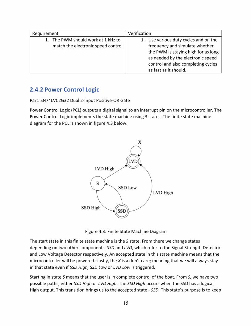
PowerControlLogic(PCL)outputsadigitalsignaltoaninterruptpinonthemicrocontroller.ThePowerControlLogicimplementsthestatemachineusing3states.ThefinitestatemachinediagramforthePCLisshowninfigure4.3below.
Figure4.3:FiniteStateMachineDiagram
ThestartstateinthisfinitestatemachineistheSstate.Fromtherewechangestatesdependingontwoothercomponents.SSDandLVD,whichrefertotheSignalStrengthDetectorandLowVoltageDetectorrespectively.Anacceptedstateinthisstatemachinemeansthatthemicrocontrollerwillbepowered.Lastly,theXisadon’tcare;meaningthatwewillalwaysstayinthatstateevenifSSDHigh,SSDLoworLVDLowistriggered.
StartinginstateSmeansthattheuserisincompletecontroloftheboat.FromS,wehavetwopossiblepaths,eitherSSDHighorLVDHigh.TheSSDHighoccurswhentheSSDhasalogicalHighoutput.Thistransitionbringsustotheacceptedstate-SSD.Thisstate’spurposeistokeep

16
themicrocontrollerONuntiltheboatisbackinsignalrangeofthehandheldcontroller.ItfollowsthatSSDLowwouldbringustoS.Thisisbecauseoncewearebackintosignalrangewewanttheusertocontinueenjoyingtheboat.
FromSSDwecanalsotransitionwithLVDHigh.ThistransitiontakesustotheacceptedstateLVD.TheotherpathtothisstateisfromSandreceivingLVDHighasaninput.LVDHighmeansthattheLVDhastriggeredandwearelowonbattery.OnceweareinLVD,wewillneverleavethisstate.ThisisbecausewhentheLVDhastriggered,thereisclosetonopowerleft.Thus,theuserwillnotbeabletousetheboatuntilithasreachedhome.
ThePowerControlLogicwillbeimplementedusinglogicgatesduetotheirlowcostandlowenergyusage.ThePCLwilltaketheoutputfromtheLowVoltageDetectorandstoreitusingasimpleORgate.TheORgatesusedwillbea2-bitORgate,withoneinputbeingtheoutputfromtheLowVoltageDetectorandonebitbeingtheoutputfromtheORgate(figure4.4).ThisisthemostefficientwayofstayinginstateLVD.TherewillbeasecondORgatewhichtakesinputfromthepreviousORgateaswellastheSignalStrengthDetector.
Figure4.4:ControlLogicforLVD&SSDcomponents
Table4.1:TruthTableforPCL
PowerControlLogic SignalStrengthDetectorLOW HIGH
LowVoltageDetector LOW LOW HIGHHIGH HIGH HIGH
Withthisconfigurationofgates,wecanturntheswitchonandoffbasedonSSD’soutput,andkeepitturnedonwhentheLVDtriggersatleastonce.OurpreferredchipforthisisaTexasInstrumentsSN74LVC2G32[16].Thisisadualgatechipwith2-bitgates.Wechosethischipduetoitsreliability,lowcost,andabilitytohaveanoperatingvoltageof3.3V[16].

17
Requirements Verifications1. OutputalogicalHIGH3V(+/-5%)
whenSignalStrengthDetectoroutputsalogicalHIGH.
1. UsetheoscilloscopetodetectwhetheraHIGH3V(+/-5%)outputisgeneratedwhentheSignalStrengthDetectoroutputsalogicalhighA. Testthetransitionfromlogical
LOWtoHIGH2. OutputalogicalLOW0V(+/-5%)
whenSignalStrengthDetectoroutputsalogicalLOW,andLowVoltageDetectorhasnotoutputalogicalHIGH3V(+/-5%)yet.
2. Usetheoscilloscopetodetectwhetheralow0V(+/-5%)outputisgeneratedSignalStrengthDetectoroutputsalogicalLOWA. Testthetransitionfromlogical
LOWtoHIGH3. OutputalogicalHIGH3V(+/-5%)
whenLowVoltageDetectoroutputsalogicalHIGH3V(+/-5%),anddoesnotchangeoutputwhenSignalStrengthDetectorchangesvalue.
3. UsetheoscilloscopetodetectwhetheraHIGH3V(+/-5%)outputisgeneratedwhenLowVoltageDetectoroutputsalogicalHIGHA. TeststartingfromSSDlogicalLOWB. TestcontinuingswitchingSSD
logicalHIGHandLOW4. OutputalogicalLOW0V(+/-5%)
whenLowVoltageDetectoroutputsalogicalLOW0V(+/-5%)
4. UsetheoscilloscopetodetectwhetheraLOW0V(+/-5%)outputisgeneratedwhenboththeLowVoltageDetectorandSignalStrengthDetectoroutputaLOW
5. UnabletooutputalogicalLOW0V(+/-5%)oncetheLowVoltageDetectorhasoutputalogicalHIGH3V(+/-5%)atleastonce.
5. UsetheoscilloscopetodetectwhetheraHIGH3V(+/-5%)outputisgeneratedafteraLOW0V(+/-5%)oncetheLowVoltageDetectoroutputsalogicalHIGH,afterithadbeenoutputtingazeroB. TeststartingfromSSDlogicalLOWC. TestcontinuousswitchingSSD
logicalHIGHandLOWD. TestcontinuousswitchingLVD
logicalHIGHandLOW(tosimulatefluctuationofLVDout)
ElectronicSpeedController(ESC)
Part:HobbywingQuicrun60A2S-3SWaterproofBrushedESC
ThepurposeoftheESCinanRCboatistocontrolboththespeedandthedirectionoftheboat.TheESCwillreceiveamessagesignalfromthePulse-WidthModulator.Thiswillbea1kHz

18
frequencyandtheencodedmessagewillcommunicatethedirectionatwhichthemotorshouldtravel.TheESCwillbeconnectedtotheexistingDCmotorintheboat.WewillusetheHobbywingQuicrun60A2S-3SWaterproofBrushedESC.WemadethischoiceprimarilybecauseitisoneofHobbywing’swaterproofoptions.Thisoptionisalsohaslow-voltagecut-offforthebattery,operatesat7.2V(compatiblewithourmotor),overheatprotectionforthemotor,andsignallossprotectionforthePulseWidthModulator[17].Thisisalsothemostcost-effectiveoptionwithallofthesefeaturesthatwehavefound.
2.5 SignalUnit
2.5.1OverviewTheSignalUnitisperhapsthemostessentialmoduleoftheproject.Itconsistsoftwomajorparts:TheRelativeSignalStrengthIndicator(RSSI)circuitandaSchmitttrigger.TheRSSIwillbecalculatedthroughtheimplementationofanICwhichsendsinformationthatwillbefilteredbytheSchmittTriggerandfinallyitwillbecommunicatedtothemicrocontroller.Figure5.1showsabasichighlevelblockdiagramofthesignalunitinterface.
Figure5.1:HighlevellayoutoftheSignalUnit

19
2.5.2RelativeSignalStrengthIndicatorCircuitTheRSSI(RelativeSignalStrengthIndicator)willbeusedtocalculatethesignalstrengthrelatingtothecurrentpositionoftheboat.Thisisavitalcomponenttohavesinceitwilldeterminewhentheboatneedstoreturntothe‘regionofoperation’.Forthisprojectthe‘regionofoperation’isdefinedtobealocationwherethesignaldetectedisgreaterthan10%ofthemaximumsignalstrength.Unfortunately,sincetheRCboatusedintheboatdidnotcomewithdetailedspecifications,wewillhavetoimplementreal-lifeteststoaccuratelycorrelatedistanceandsignalstrength.Thesetestscanbedoneeasilyusingourhandheldremotecontrollerandtheboatmotor.Wecansimplydoaseriesoftrialanderrortestsandseehowfarawayexactlytheremotecontrollercanstilldrivetheboatmotor.
TheRSSIcircuitwillmonitorthesignalstrengthcorrespondingtotheboat’scurrentlocation.ThiswillbeachievedusingtheAnalogDevices’AD8317chip.TheAD8317takesinanRFinputandoutputsavoltagethatrelatestothesignalstrength(measuredindBm).Figure5.2displaysthebasicpinlayoutschematicwhiletable5.1describestherespectiveconnections.
Figure5.2:SchematicoftheAD8317IC[18]

20
Table5.1:PindescriptionsoftheAD8317IC[18]PinNo. Mnemonic Description
1 INHI RFInput,rangingfrom-50dBmto0dBm
2 COMM DeviceCommon,connectedtolowimpedanceground
3 CLPF LoopFilterCapacitor–setspulseresponsetimeandbandwidth
4 VSET Set-pointInput
5 VOUT VoutprovidesadecreasinglinearrepresentationoftheRFsignalamplitude
6 TADJ TemperatureAdjustmentPin(chosentobe8kΩ)
7 VPOS ConnectedtoPowerSupply(3.0to5.5V)
8 INLO RFCommon
Theresistancesassociatedtosomeofthepinsinfigure5.2willvaryaccordingtotheoperationalfrequencyrangeoftheboat.Theremote-controlboatusedinthisprojectoperatesatafrequencyof2.4GHz.Basedonthedatasheet,valuesforeachpartweredetermined.Thetablesreferredtoforthedataanalysisareshownbelowastable5.2andtable5.3.

21
Table5.2:Frequencyandresistanceconsiderations[18]
Frequency RecommendedRTadj
50MHz 18kΩ
100MHz 18kΩ
900MHz 18kΩ
1.8GHz 8kΩ
1.9GHz 8kΩ
2.2GHz 8kΩ
3.6GHz 8kΩ
5.3GHz 500kΩ
5.8GHz 500kΩ
8GHz OPEN

22
Table5.3:Circuitspecificationsfor2.2GHzfrequencyoperation[18]
Parameter Conditions Minimum Type Maximum Unit
f=2.2GHz RTadj=8kΩ
InputImpedance
810||0.39 Ω||pF
±1dBDemonicRange
TA=25ºC
-40ºC<TA<85ºC
50,48 dB
MaximumInputLevel
±1dBerror -4.00 dB
MinimumInputLevel
±1dBerror -54 dB
Slope -25 -22 -19.5 mV/dB
Intercept 10 14 20 dBm
OutputVoltage(HighPowerIn)
PIN=-10dBm 0.35 0.54 0.80 V
OutputVoltage(LowPowerIn)
PIN=-35dBm 0.75 1.21 1.35 V
TheAD8317willbepoweredbythebatteryusingavoltageregulator(section2.3.3)whichwillneverletthevoltageexceeditsmaximumvoltageratingof5.5V.Lastly,theoutputvoltagewillgodirectlyintotheSchmitttriggerwhichwillthendeterminewhattocommunicatetothemicrocontroller.

23
2.5.3SchmittTriggerBysettingathresholdvaluetocompareagainst,theSchmitttriggerwillusetheoutputreceivedfromtheRSSIcircuittodetermineiftheboatneedstoreturntotheregionofoperationornot.TheSchmitttriggerwillusethesameTL331chip[2]usedinthelowvoltagedetectioncircuit.TheTL331willservethepurposeofacomparatorandwillmeasuretheoutputfromRSSIagainstareferencevalue.AschematicoftheSchmitttriggercircuitusedisshowninfigure5.3.
Figure5.3:SchematicoftheSchmitttrigger
DX(MMSZ4681T1G)isa2.4VZenerdiodethatisusedtoregulatethevoltage.TheresistorR1waschosentobea100kW,tosatisfytheminimumcurrentconditionsforthediode.
Basedonthetwocalculationsinequations1and2,itissafetoassumethataresistorvalueofa100kWisasafechoicesinceitagreeswiththeproductspecifications.
ThecomparatorwillusetheoutputfromthevoltagedividerastheinputtoVin-.Thiswillserve
asthethresholdreferencevoltage.Inthiscase,the2.4VZenerdiodewillinputavoltageof2.4VtotheresistorsR2andR3,both1MW,whichwilldivideitinhalf.Consequently,Vin
-,willbefedwithaconstantvoltageof1.2V.
Ascanbeseenfromtable5.3,themaximumvoltageoutputtedwillbe1.21V.Thisvoltageisassociatedwiththeweakestsignal,whichcanbeconfirmedbythefigureA.1,presentintheappendix.Vin
+willreceiveitsinputfromtheRSSIrangingfrom0to1.21V(table5.3)with0Vindicatingthemaximumsignalstrength.Uponsimulation,thecircuitinFigure5.4gaveustheoutputshownintable5.4andfigure5.4.

24
Table5.4:SchmitttriggercircuitsimulationresultsVin+ Output0 LOW0.2 LOW0.4 LOW0.6 LOW0.8 LOW1.0 LOW1.2 HIGH
Figure5.4:Schmitttriggercircuitsimulationresults
Thesimulationresultsverifythatthecircuitwilloutputahighassoonasalowlevelsignalisdetected.Finally,thisHIGH/LOWoutputwillgointothemicrocontrollerwhichwillthendeterminehowtoproceed.
Note: Figure5.4usesaconsistentoutputvoltageof3.3Vtomakethegrapheasiertointerpretandunderstand.Inreallifeexperimentation,thevoltagewillrangefrom4.5to9VduetothefactthatVCCisconnecteddirectlytothebattery.Sincetheinputthatthemicrocontrollerreceivesisadigitallogicinput,thevalueofthevoltageitselfwillnotmatter(allvoltagesrangingfrom4.5Vto9VwillresultinthesameoutputofaHIGH);unlessitis0orveryclosetoitwhichcorrespondstoaLOW.

25
Requirements Verifications1. Outputa:
A. logicHIGHtothemicrocontrollerwhentheRSSIoutputisgreaterthanorequalto1.2V(+/-5%).
B. logicLOWtothemicrocontrollerwhentheRSSIoutputislessthan1.2V(+/-5%)
1. Useadcpowersupplytopowerthecircuitandthenusetheoscilloscopetodetectif:
A. aHIGHoutputisgeneratedwhenthevoltageacrossR4,1MW,isgreaterthanorequalto1.2V(+/-5%)(figure5.3)
B. aLOWoutputisgeneratedwhenthevoltageacrossR4,1MW,islessthan1.2V(+/-5%)(figure5.3)
2.5.4SensorPart:XtrinsicMAG3110
Forthesensorunit,wewillbeusingonesensor,amagnetometer.Amagnetometerisusedtocalculateyourdirectionwithregardstothemagneticpolesoftheearth.Byusingthiswecanaligntheboatinaccordancetothedesiredheading.Magnetometershave,onaverage,averylongOutputDataRate(ODR)comparedtotherestofthedigitalaspectsofthisproject.Mostcost-effectiveoneshaveapproximately80HzODR[12,13].Thiswouldnormallybeabottleneck,butbecauseofthecomplexityoftheotheroperationsinthecircuit,weareabletooptimizereadingthemagnetometerinthemicrocontroller.ThissensormustoperateatavoltageofVCC
(3.3V).ItmustalsouseI2CcommunicationbecauseofthefewerI/Oportsrequiredandafasterreadspeed.Lastly,thissensormustbeabletobepolled.Theoptimizationthemicrocontrollerwilltakecanonlybeachievedifitisabletoprocessinstructionswhilethemagnetometerisgettingitsdataready.
Somemagnetometerscalculatedirectionbasedontheaverageofseveralsamples.Thisisdesirableforusbecauseitwouldreduceerror.However,manyofthemagnetometersthatdothisaresignificantlymoreexpensivesoitisnotastrictrequirement,suchastheHoneywellHMC5883L[12].
XtrinsicMAG3110isthemostcosteffectiveoneforourneeds.Thisunitischeaperthanmanycompetitors[12,14,15]Duetothepresenceof“DR_STATUS”thischipisabletobepolledtoseeifthedataisready.CombiningthiswiththeslowerODRmeansthatwecandomanycalculationoptimizationsbasedonwhenthisdataisready

26
2.5.5AntennaArrayPart:TexasInstrumentsCC2500RGPR
WehavechosentheTexasInstrumentsCC2500RGPRbecauseofitslowcost,availability,andsatisfactionofourneeds.Itisatransceiver.Wewillbeorderingseveralofthese,mostlikely6.Wehaveconstructedatestingmethodologytodecidewheretheantennasneedtobe,basedonasetofexperimentsdoneinSlovenia.Tocalculateangleofarrivalwewillbeusingthealgorithmdocumentsonpage240and241ofAngleofArrivalestimationalgorithmsusingReceivedSignalStrengthIndicator[20].Wewillstartbyplacingthetransceiversaroundonacircularboardwithdiameter5cm.Wewillplacethematvariouspointsallevenlyseparated.Usingdifferentdistancestodiscoverthepositionthatwillgiveusasmosta+/-10-degreeerrorforangleofarrival.Wewillplacethisantennaarrayontheground,andtestit’sreadingsfromdistancesof1mto30m.Wewillalsobetestingforangles,inincrementsof20degreesfrom0to360[20].
Requirement Verification1. Algorithmestimatesangleofarrival
within10degreesoftruevalue.1. Use6antennastocreateanantenna
arrayinavariationofahexagon.Tryvariousdistancesfrombeing1cmto3cmapart.Testestimatedangleofarrivalusingthealgorithmdocumentedintheaforementionedpaper.
3 ToleranceAnalysisThehighestriskinourdesignisgoingtocomefromtheSignalUnit.Signalcanbeinterferedwithbynumerablethingssuchasrainortheradiationfromthesun.Thisinterferencecanaffecttheaccuracyofthesignal,addingerrorintothecontrolsystem.Withoutthesignaldetectionworkingperfectly,wehavenoreferenceofwherewearecomparedtoourstartinglocation.Lastly,ifthedataisflawedwewillwastepoweringuidingtheboatinthewrongdirection.However,wewillmitigatealloftheserisks.Onesolutionistousesixantennasignalsinsteadofone.Thiswillmakethesignalmuchmoreaccurateandreducetheinterferencefromsolarradiation.Thiswillalsogiveusaproperestimatedangleofarrival.Wewillbetestingavarietyofantennaconfigurationstofindthebestpossibleone.
27
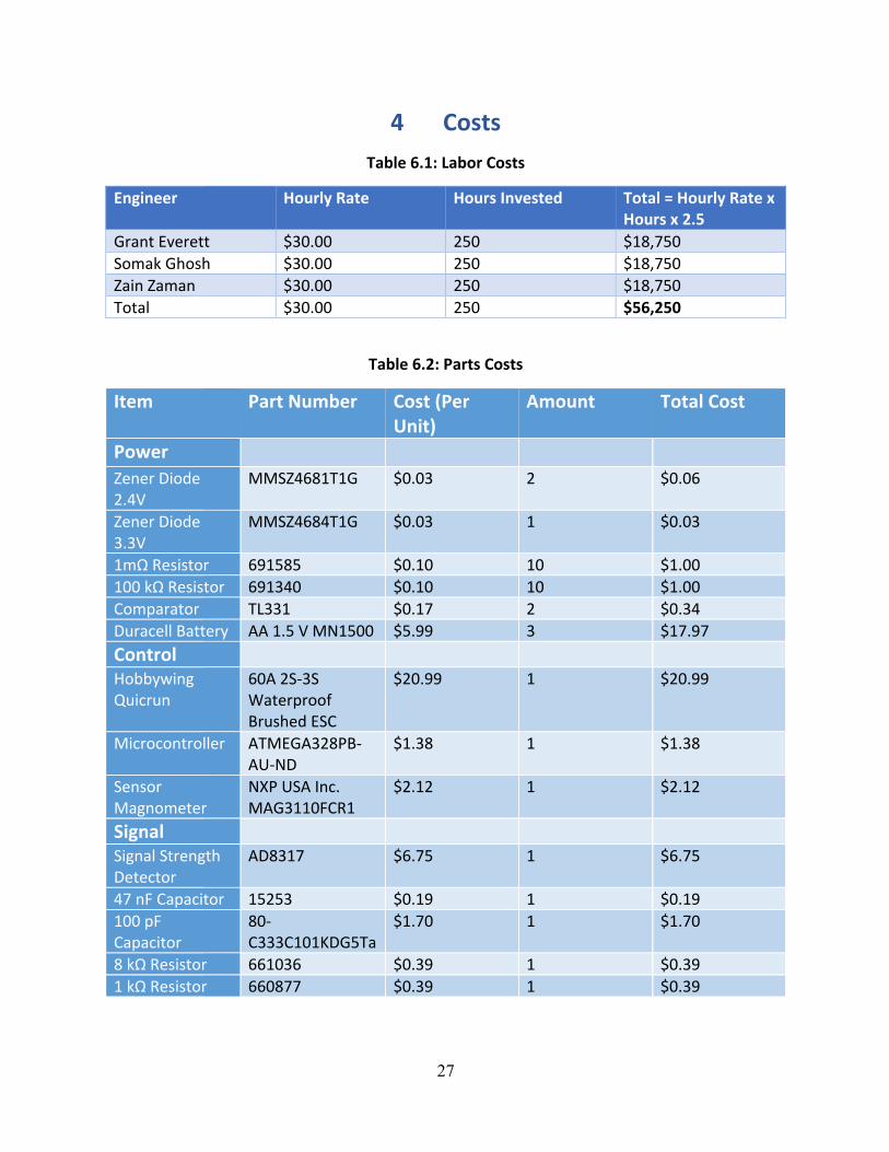
4 CostsTable6.1:LaborCosts
Engineer HourlyRate HoursInvested Total=HourlyRatexHoursx2.5
GrantEverett $30.00 250 $18,750SomakGhosh $30.00 250 $18,750ZainZaman $30.00 250 $18,750Total $30.00 250 $56,250
Table6.2:PartsCosts
Item PartNumber Cost(PerUnit)
Amount TotalCost
Power
ZenerDiode2.4V
MMSZ4681T1G $0.03 2 $0.06
ZenerDiode3.3V
MMSZ4684T1G $0.03 1 $0.03
1mΩResistor 691585 $0.10 10 $1.00100kΩResistor 691340 $0.10 10 $1.00Comparator TL331 $0.17 2 $0.34DuracellBattery AA1.5VMN1500 $5.99 3 $17.97Control HobbywingQuicrun
60A2S-3SWaterproofBrushedESC
$20.99 1 $20.99
Microcontroller ATMEGA328PB-AU-ND
$1.38 1 $1.38
SensorMagnometer
NXPUSAInc.MAG3110FCR1
$2.12 1 $2.12
Signal SignalStrengthDetector
AD8317 $6.75 1 $6.75
47nFCapacitor 15253 $0.19 1 $0.19100pFCapacitor
80-C333C101KDG5Ta
$1.70 1 $1.70
8kΩResistor 661036 $0.39 1 $0.391kΩResistor 660877 $0.39 1 $0.39

28
Antenna TexasInstrumentsCC2500RGPR
$2.91 6 17.46
Total $62.77
4.3TotalCosts
TotalCost=Parts+Labor=$56,312.77
5 SchedulesWeek Task Delegation2/6–2/12 WorkonProjectProposal Grant
WorkonProjectProposal SomakWorkonProjectProposal Zain
2/13–2/19 WorkonProjectProposal,SignupforMockDesignReview,FinishEagleCad
Grant
WorkonProjectProposal,SignupforMockDesignReview,FinishEagleCad
Somak
WorkonProjectProposal,SignupforMockDesignReview,FinishEagleCad
Zain
2/20–2/26 WorkonDesignReviewDocument,SignupforDesignReview
Grant
WorkonDesignReviewDocument,SignupforDesignReview
Somak
WorkonDesignReviewDocument,SignupforDesignReview
Zain
2/27–3/5 DesignReview&OrderParts GrantDesignReview&OrderParts SomakDesignReview&OrderParts Zain
3/6–3/12 Build&testPCL GrantDesignState-SpaceSystem&CreateSimulinkforController
Somak
BuildtheLVDC Zain

29
3/13–3/19 CodeMicrocontroller GrantDesignState-SpaceSystem&CreateSimulinkforController
Somak
BuildtheLVDC Zain3/20–3/26 ConfigureRFReceiver Grant
ConfigureRFReceiver SomakBuildtheLVDC Zain
3/27–4/2 BuildMicrocontrollerPCB GrantBuildtheSSDC SomakBuildtheSSDC Zain
4/3–4/9 IntegrateControlUnitwithSomak
Grant
BuildtheSSDC SomakBuildtheSSDC Zain
4/10–4/16 Integrateallparts GrantIntegrateallparts SomakIntegrateallparts Zain
4/17–4/23 FinalChanges&MockDemo GrantFinalChanges&MockDemo SomakFinalChanges&MockDemo Zain
4/24–4/30 Demo GrantDemo SomakDemo Zain
5/1–5/7 WriteFinalPaper GrantWriteFinalPaper SomakWriteFinalPaper Zain
6Ethics&SafetyThereareseveralethicalguidelinesfromtheIEEECodeofEthicswhichapplytoourproject.Wewillfollowtheseguidelinesascloselyaspossible.Theguidelinesinclude–tobehonestregardingallcollecteddata[19],rejectbriberyfromanysource[19],undertaketechnologicaltasksonlywiththerequiredcompetenceandsafetyknowledge[19],nottoengageinanyactsofdiscrimination,andassisttheprofessionaldevelopmentofourpeers[19].Thismeansthatwewillworktowardsbuildingourentireprojectwithoutanyoutsidehelp,andundertherulesoftheclass[19].Wewillalsopurchaseseveralcomponentsofourdesign,howeverwewillindividuallybuildamajorityofourdesignuniquelyandindependently.Whendiscussingwithouradvisorandtheprofessorsoftheclasswewillalwayspresentaccuratedataandtruthfully

30
presentourprojectregardlessofitsfunctionality[19].Lastly,wewilladheretoallsafetyguidelinesandtakeeveryprecautionnecessarytosafelytestourboat[19].Ourboatwillhaveelectricalcomponentsandwillneedtohaveseveralextraprecautionstakentomakeitsafeforthegeneralcommunity.Wewillalsonotdiscriminateintheuseofthisboatortheboattechnologyamongstanyone(saveforyoungchildrenwhowillneedsupervision).
Thereareseveralsafetyguidelinesthatwewilladheretocloselyaswell.First,wewillfollowallofthegivensafetyguidelinesputforthbyECE445,ECEIllinois,andtheUniversityofIllinoiswhileusingthelaboratoryequipment.Seeingthatwearealsomodifyingachildren’stoywithelectronicsthatwillbeonthewaterwewilltakeprecautionswhentestingsuchastestingasagroup,testinginemptyopenwater,andthoroughlyworkingtowaterprooftheboat.Theboatwillhavemanyelectricalcomponentswhichwewillhavetomakesurewillnotbedangerousinthewater.Wewilluseamarine-gradeepoxywhichwillbeusedtore-sealpre-existingelectricalcomponentsandsealallnewelectricalcomponentswithinthehulloftheboat.
Therearenoexistingregulationsformodifyingreplicaboats,however,theredoesexistaNorthAmericaModelBoatAssociation(NAMBA).Thisgoverningbodyhassafetyregulationsaboutracingmodelboats.Ifthereisoverlaponanyofthetechnologyonourboatwiththeirstandardmodelboat,wewilladheretotheirregulations.Currently,
Fortesting,wehavecontactedtheActivitiesandRecreationCenteroncampusandwilllookforapprovaltosafelytestthere.

31
References
[1] “Duracell Coppertop MN1500.” https://d2ei442zrkqy2u.cloudfront.net/wp-content/uploads/2016/03/MN1500_US_CT1.pdf [Feb. 21, 2017]
[2] “TL 331 Single Differential Comparator.” http://www.ti.com/lit/ds/symlink/tl331.pdf , Jan. 2015 [Feb. 21, 2017]
[3] “Zener Voltage Regulators.” http://www.onsemi.com/pub_link/Collateral/MMSZ4678T1-D.PDF, Nov.2013[Feb. 21, 2017]
[4] Atmel, “ATmega328P”, 2016, Available: http://www.atmel.com/Images/Atmel-42735-8-bit-AVR-Microcontroller-ATmega328-328P_Datasheet.pdf [Feb. 22, 2017]
[5] Digi-Key, Microchip Technology ATMEGA328PB-AU, 2017, Available: http://www.digikey.com/product-detail/en/microchip-technology/ATMEGA328PB-AU/ATMEGA328PB-AU-ND/5638812 [Feb. 22, 2017]
[6]“L4931”https://cdn-shop.adafruit.com/product-files/2166/2166datasheet.pdf,Oct.2013[March10,2017]
[7] Xtrinsic, “Xtrinsic MAG3110 Three-Axis, Digital Magnetometer”, 2013, Available: http://cache.freescale.com/files/sensors/doc/data_sheet/MAG3110.pdf [Feb. 22, 2017]
[8] avrProgrammer, ATmega328p Power Consumption, Available: https://www.avrprogrammers.com/howto/atmega328-power [Feb. 22, 2017]
[9]EvanWallace,“FiniteStateMachineDesigner”,2010,Available:https://www.cefns.nau.edu/~edo/Classes/CS315_WWW/Tools/fsm.html[Feb. 22, 2017]
[10]Creately,Available:https://creately.com/app/?tempID=gc7qvpsj1&login_type=demo#[Feb. 22, 2017]
[11]Nexperia,“74HC2G32;74HCT2G32”,Available:http://assets.nexperia.com/documents/data-sheet/74HC_HCT2G32.pdf[Feb. 22, 2017]
[12] Honeywell, “3-Axis Digital Compass IC HMC5883L”, 2010, Available: https://cdn-shop.adafruit.com/datasheets/HMC5883L_3-Axis_Digital_Compass_IC.pdf [Feb. 22, 2017]
[13] Digi-Key, “NXP USA Inc. MAG3110FCR1”, 2017, Available: http://www.digikey.com/product-detail/en/nxp-usa-inc/MAG3110FCR1/MAG3110FCR1CT-ND/3524267 [Feb. 22, 2017]
[14] Xtrinsic, “Xtrinsic MAG3110 Three-Axis, Digital Magnetometer”, 2013, Available:
http://cache.freescale.com/files/sensors/doc/data_sheet/MAG3110.pdf [Feb. 22, 2017]

32
[15] Digi-Key, “Memsic Inc. MMC34160PJ”, 2017, Available: http://www.digikey.com/product-detail/en/nxp-usa-inc/MAG3110FCR1/MAG3110FCR1CT-ND/3524267 [Feb. 22, 2017]
[16] Texas Instruments, “SN74LVC2G32 Dual 2-Input Positive-OR Gate”, 2015, Available:
http://www.ti.com/lit/ds/symlink/sn74lvc2g32.pdf [Feb. 22, 2017].
[17]“HobbywingQuicrun60A2S-3SWaterproofBrushedESCfor1/10.”https://hobbyking.com/en_us/hobbywing-quicrun-60a-2s-3s-waterproof-brushed-esc-for-1-10.html[Feb. 22, 2017]
[18] “Analog Devices AD8317.” http://www.analog.com/media/en/technical-documentation/evaluation-documentation/AD8317.pdf [Feb. 22, 2017]
[19] "IEEE IEEE Code of Ethics." IEEE - IEEE Code of Ethics. N.p., n.d. Web. 08 Feb. 2017. http://www.ieee.org/about/corporate/governance/p7-8.html
[20] “Angle of Arrival estimation algorithms using Received Signal Strength Indicator” – Marko Malajner, Dusan Gleich, Peter Planinsic, 2015. http://www.dlib.si/stream/URN:NBN:SI:DOC-O4FYKB1C/e39456e9-60ae-4cc1-b4dd-9ee7e73f2b53/PDF [Mar. 16, 2017]
[21] Digi-Key, “TexasInstrumentsCC2500RGPR”, 2017, Available: http://www.digikey.com/product-detail/en/texas-instruments/CC2500RGPR/296-38562-2-ND/4695539 [Mar. 16, 2017]

33
Appendix
FigureA.1:AD8317VOUTvsPIN
FigureA.2:AD8317PinLayoutexample