Embed Size (px)
Citation preview

The ATLAS Detector Positioning System (ADEPO) to Control Moving Parts During ATLAS Closure IWAA 2016 (03-07 Oct.) - Grenoble - France J.-C. Gayde, D. Mergelkuhl, M. Raymond, CERN – Geneva – Switzerland M. Daakir, IGN - Marne la Vallée - France M. Dönszelmann, Radboud University, Nijmegen, The Netherlands Vitali Batusov, JINR - Dubna - Russia

Table of contents
IWAA 2016 - 03-07 October 2016
• Introduction
• System Concept • ADEPO system specifications
• Choice of Layout and Sensors
• ADEPO system description
• Validation setup and results
• Installation • Installation in the ATLAS cavern
• Commissioning
• ADEPO user interface
• Results • ATLAS closure
• Monitoring short/medium term
• Conclusion
• Outlook

Introduction
ATLAS facts
• Length 44 m, diameter 25 m
• Weight: 7000 t
• Data: 3200 TB/year
• 3000 scientists from 38 countries
ATLAS requirements • Regular maintenance and shut down
periods • Implies movement open/close of
large sub-detectors of up to 900 t • Manual adjustment and survey is
iterative and time consuming New ADEPO system should provide • Near real-time results • Speed up closure • Precise re-positioning • Entirely managed by ATLAS
Technical Coordination
IWAA 2016 - 03-07 October 2016

ADEPO system specifications
• 6 detectors to be re-positioned • 2x ECT – 240 t
• 2x SW – 103 t
• 2x EB – 900 t
• In total ~2500 t of detector are moved
• Environmental constraints • Resist to 1 Tesla magnetic field
• Radiation dose of 2Gy for lifetime
IWAA 2016 - 03-07 October 2016
• Measurement requirements • Measurement cycle < 30 seconds
• Two measurement modes
• Closure (on demand)
• Monitoring during run time
• Parallel to ATLAS coordinate system (shifts tolerable)
• Installed and commissioned during Long Shutdown 1 (LS1) period (2013-2014)
=> project < 2 years
• Measurement range • Along X : +- 20 mm (radial)
• Along Y: -10/+30 mm (vertical)
• Along Z+ (side A): -10/+40 mm
• Along Z- (side C): -40/+10 mm
• Repositioning 0.3 mm
• Measurement precision • 0.1 mm at 1 sigma level along XZ
directions (radial and longitudinal)

Choice of layout and sensors
• BCAMs as proven camera sensors originally developed for ATLAS
• BCAMs attached to feet => max. stability
• Independency of each BCAM line
• Optical 2D measurement => less sensors
• Redundant system for error detection with 4 BCAMs and up to 8 prisms per detector
• BCAMs with protection to avoid damage
• Passive targets on mobile parts => no cabling
BCAM’s field of view
X
Y
Z
IWAA 2016 - 03-07 October 2016
Layout based on experience of previous alignment systems

ADEPO System description System is based on:
• 28 BCAMs on feet/rail system
• 44 passive targets (corner cubes)
• 1 driver and 4 multiplexers
• 24 protections
• Reference ATLAS feet/rail system
• LWDAQ for acquisition and measurement
• Movement/Positioning using push/pull system
• System is considered as additional system and traditional survey is maintained!
• New references after each closure!
IWAA 2016 - 03-07 October 2016
• Adjustment concept: • Adjustment using additional observations (detectors rigid body) • Blunder detection: Application of IRLS (Iteratively Reweighted Least Square)
• K. Jacobsen, “Block Adjustment. Institute for Photogrammetry and Surveying Engineering”, Univ. Hanover, 2002, Germany
• Successfully tested in validation setup, still to be integrated in the present version of ADEPO

Validation setup and results • Demand: 0.1 mm at 1 σ
• Repeatability: < 0.005 mm
• Displacement results: 0.04 +- 0.01 mm at 1 σ
• Verified by AT401 for detector EBA/EBC
• IRLS (Iteratively Reweighted Least Square) proved efficiency
IWAA 2016 - 03-07 October 2016
Result of displacement test at 2.1 m mean offset = 35 µm+- 11 µm

Installation in ATLAS cavern • Installation and adjustment in ATLAS open
position => prisms invisible, first verification can only occur after closure
• Inside detector behind layers of muon chambers
• Integration in completed detector => limited lines of sight/space
• Adjustments by AT401 in absolute system mandatory using special adapter plate
IWAA 2016 - 03-07 October 2016

Commissioning
• Problem of hidden lines on ECT
• Hidden lines in saddle beams
• Due to difference of as-built to 3D-model
• Concession to integration constraints with 4 BCAMs on BT warm structure
• Movement of BCAMs on BT structure due to deformation of support structure
IWAA 2016 - 03-07 October 2016
• Separation of flashes
• Change of flash times
• Definition of zones for BCAM measurements in case of 2 prisms
• Identified broken connector

ADEPO user interface • Interface and server structure integrated in
technical infrastructure (ATLAS network)
• GUI with 2 modes for closure and monitoring
• Closure measurement time defined in sec.
• Monitoring default 10 loops
• Data storage via DIP (Data Interchange Protocol) in ATLAS database
IWAA 2016 - 03-07 October 2016

Results ATLAS closure
• Intensive use of ADEPO for closure of Technical Stop 2015/16
• Six detectors closed with in average 3 iterations of BCAM measurements
• Maximum of 7 iterations
• Average time for mechanical correction ~ 20 minutes
• Average difference of ADEPO results to reference position
• 0.3 mm along monitored X, Z directions (or closer with respect to nominal values)
• Results for each detector confirmed by Laser Tracker measurements
• Single iteration for survey
IWAA 2016 - 03-07 October 2016

Short-term results for ECT – B-Fied on/off • Demand from physics side for movement of ECT under magnetic field for
field map
• Due to strong magnetic field no survey measurements available previously (only Muon Barrel alignment system)
• Quench at measure 200
• Back to nominal after 1 week with magnet down
• Movement of 3-4 mm with b-field of BT and ECT
• Deformation of BCAM support due to B-field
• US-IP-Z, USA-IP-Z
IWAA 2016 - 03-07 October 2016

Medium term results (1 month)
• One month repeatability on individual BCAMs of Small Wheel and JD C-side
• Average precision (repeatability 1 month): 2-3 µm
• BCAM lines of 1.5-3.0 m measure a detector stability within ± 0.015 mm
Conditions: No change of magnetic field!
IWAA 2016 - 03-07 October 2016

Conclusion
• System installed and commissioned during LS1 2013-2014
• ADEPO has two operating modes:
• On-demand for closing operation
• As monitoring system (magnetic field, long-term)
• First use for relative movements during closure of LS1
• Successful use in TS2015/16 with gain of 2-3 hours for each of the 6 moving detectors during closure operation
• Average 3 iterations using ADEPO
• Geodetic survey of detectors maintained and justified by long-term movements at level of civil engineering
• ADEPO generates substantial gain in time, precision (relative) and comfort for technical coordination and survey team !
IWAA 2016 - 03-07 October 2016

Outlook
• Consolidation of few BCAM lines due to differences in 3D model with respect to the as-built construction
• Complete implementation of:
• proposed adjustment using additional observations
• blunder detection to identify in-valid measurements
• Acquisition of reference data after each movement during detector opening to minimize influence of mechanical deformation
• Weight of shifted detectors represents ~2500 tons
• Possible increase of time savings at a level of ~4 hours for each single detector closure
Up to 20 % gain in ATLAS closure schedule for the technical coordination
IWAA 2016 - 03-07 October 2016

Thanks for your attention!
Candidate Event Selected in Higgs Search Analyses
IWAA 2016 - 03-07 October 2016


BCAM equipment Brandeis CCD Angle Monitor – BCAM: • BCAM resists magnetic field and radiation as
developed for ATLAS Muon system • Sensor size 344 x 244 pixel, 10 µm/pixel • Field of view: 40 mrad x 30 mrad • Camera focal length: 75 mm • Minimal working distance 0.7 m • Absolute precision 50 µrad (2D) • Relative precision 5 µrad (2D) • Isostatic mount system • Delivered calibrated • Laser diode 650 nm
BCAM
prism
IWAA 2016 - 03-07 October 2016

Results ECT ramp up/down (short-term) • Due to high magnetic field no survey measurements available
before (only Muon alignment system)
• Demand from physics side for movement of ECT under magentic field for magentic field map
IWAA 2016 - 03-07 October 2016

Formulas corner cubes
• BCAMs perpendicular to beam/prism (5° => error ~10 µm)
• In case of BCAM-Prism measurements the virtual source is measured at twice the distance of the real one
• Use of theoretical values for projection of D on Z axis
• In the BCAM mount system the following formula applies:
sourceVirtualCCD
IWAA 2016 - 03-07 October 2016

Formulas corner cubes
• Projection of D on Z-axis is:
• Error propagation corresponds to:
• Precision of 4 mm at 2 m results in an error of 5 um for XY directions
Virtual source
Virtual source
IWAA 2016 - 03-07 October 2016

Validation results
Result of displacement test at 2.1 m: mean offset = 35 µm+- 11 µm
Resid
ual t
o m
ean
(µm
)
100
µm
Resid
ual t
o m
ean
(µm
)
100
µm
Resid
ual t
o m
ean
(µm
) 10
0 µm
Re
sidua
l to
mea
n (µ
m)
100
µm
IWAA 2016 - 03-07 October 2016

Adjustment concept
• Single detector is considered as rigid and non-deformable object
• As consequence
• Observations are linked by constraints
• Calculation of prism coordinates is linked by additional observations
• Equation systems for a single detector with 4 prisms:
IWAA 2016 - 03-07 October 2016
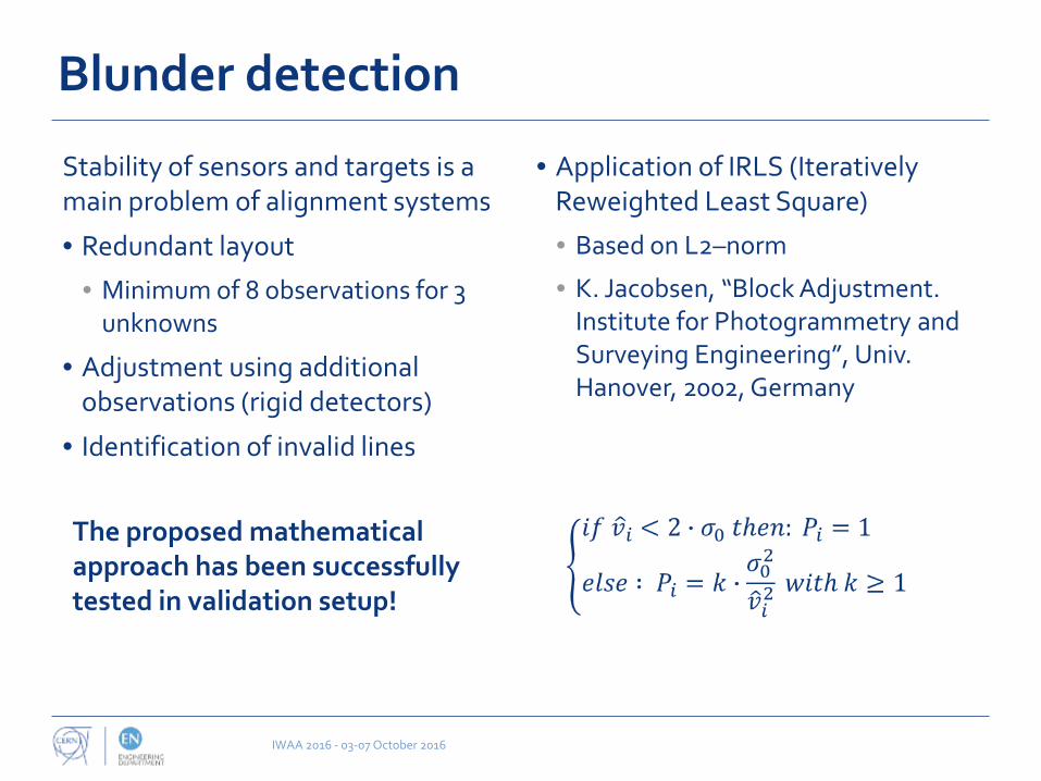
Blunder detection
Stability of sensors and targets is a main problem of alignment systems
• Redundant layout
• Minimum of 8 observations for 3 unknowns
• Adjustment using additional observations (rigid detectors)
• Identification of invalid lines
• Application of IRLS (Iteratively Reweighted Least Square)
• Based on L2–norm
• K. Jacobsen, “Block Adjustment. Institute for Photogrammetry and Surveying Engineering”, Univ. Hanover, 2002, Germany
The proposed mathematical approach has been successfully tested in validation setup!
IWAA 2016 - 03-07 October 2016

Blunder detection
Stability of sensors and targets is a main problem of alignment systems
• Redundant layout
• Adjustment using additional observations (rigid detectors)
• Application of IRLS (Iteratively Reweighted Least Square)
• Identification of invalid lines
IWAA 2016 - 03-07 October 2016