Embed Size (px)
Citation preview
BA 44/96
The Assessment ofConcrete Highway
Bridges and Structures
Summary: This Advice Note provides guidance on the assessment of concretehighway bridges and structures and accompanies BD 44 (DMRB 3.4.14).It supersedes BA 44/90.
THE HIGHWAYS AGENCY
THE SCOTTISH OFFICE DEVELOPMENT DEPARTMENT
THE WELSH OFFICEY SWYDDFA GYMREIG
THE DEPARTMENT OF THE ENVIRONMENT FORNORTHERN IRELAND
ELECTRONIC COPY NOT FOR USE OUTSIDE THE AGENCY.PAPER COPIES OF THIS ELECTRONIC DOCUMENT ARE UNCONTROLLED

November 1996
REGISTRATION OF AMENDMENTS
Amend Page No Signature & Date of Amend Page No Signature & Date ofNo incorporation of No incorporation of
amendments amendments
Volume 3 Section 4Part 15 BA 44/96 Registration of Amendments
ELECTRONIC COPY NOT FOR USE OUTSIDE THE AGENCY.PAPER COPIES OF THIS ELECTRONIC DOCUMENT ARE UNCONTROLLED

REGISTRATION OF AMENDMENTS
Amend Page No Signature & Date of Amend Page No Signature & Date ofNo incorporation of No incorporation of
amendments amendments
Registration of AmendmentsVolume 3 Section 4
Part 15 BA 44/96
November 1996ELECTRONIC COPY NOT FOR USE OUTSIDE THE AGENCY.
PAPER COPIES OF THIS ELECTRONIC DOCUMENT ARE UNCONTROLLED

DESIGN MANUAL FOR ROADS AND BRIDGES
November 1996
VOLUME 3 HIGHWAYSTRUCTURES:INSPECTION ANDMAINTENANCE
SECTION 4 ASSESSMENT
PART 15
BA 44/96
THE ASSESSMENT OF CONCRETEHIGHWAY BRIDGES ANDSTRUCTURES
Contents
Chapter
1. Introduction
2. Use of Annex A - the Commentary
3. References
4. Enquiries
Annex A. – Commentary on Appendix Aof BD 44/95
ELECTRONIC COPY NOT FOR USE OUTSIDE THE AGENCY.PAPER COPIES OF THIS ELECTRONIC DOCUMENT ARE UNCONTROLLED

Chapter 1Introduction
Volume 3 Section 4Part 15 BA 44/96
1. INTRODUCTION
in
ld
y
General
1.1 This Advice Note provides guidance on the use oBD 44 (DMRB 3.4.14), The Assessment of ConcreteHighway Bridges and Structures, and should be usedin conjunction with the Standard.
1.2 The major part of this document is contained inAnnex A which is set out in the form of a commentaryon the Standard. It contains explanations for the machanges from the design code, BS 5400: Part 4, andgives advice on the interpretation of the assessmentrequirements. Also included are comments andreferences which provide additional informationappropriate to special situations. Where suchsituations arise, any special method of analysis orvariation of criteria proposed for an assessment shoube agreed with the Overseeing Organisation.
Scope
1.3 In view of the problems associated with thecorrosion of tendons in grouted duct post-tensioning,all bridges with this form of construction are to beexamined in accordance with BD 54, Post-tensionedConcrete Bridges; Prioritisation of SpecialInspections, (DMRB 3.1.2). The condition of tendonsin these structures should be investigated inaccordance with BA 50, Post-tensioned ConcreteBridges; Planning, Organisation and Methods forCarrying Out Special Inspections, (DMRB 3.1.3).
1.4 Structures with corroded reinforcement orprestressing steel should be assessed in conjunctionwith BA 51, The Assessment of Concrete StructuresAffected by Steel Corrosion, (DMRB 3.4.13).Structures suspected of suffering from Alkali-SilicaReaction (ASR) should be assessed in conjunctionwith BA 52, The Assessment of Structures affected bAlkali-Silica Reaction, (DMRB 3.4.10).
Implementation
1.5 This Advice Note should be used in all futureassessments of structures or structural elements.
November 1996ELECTRONIC COPY NO
PAPER COPIES OF THIS ELECTRO
It should also be taken into account in assessmentscurrently at hand unless, in the opinion of theOverseeing Organisation, this would result in anunacceptable additional expense or delay.
f
1/1T FOR USE OUTSIDE THE AGENCY.NIC DOCUMENT ARE UNCONTROLLED
Volume 3 Section 4Part 15 BA 44/96
November 1996
Chapter 2Use of Annex A - the Commentary
2. USE OF ANNEX A - THE COMMENTARY
2.1 The format of the commentary is based on theclause numbering used in Appendix A of BD 44(DMRB 3.4.14) To assist in identifying these clauses,section headings and subheadings have been retained.All other headings have been omitted for clarity.
2.2 Comments are given on those clauses where thechanges from BS 5400: Part 4 are substantial or arenot self evident. There are also comments on some ofthe clauses in BD44 which have been marked as “Notapplicable to assessment”. A number of these clausesrelate to serviceability criteria and should only beincluded in an assessment on the direction of theOverseeing Organisation.
2.3 In the commentary there are many references todetailed aspects of BS 5400: Part 4. Therefore, togain the maximum benefit from the commentary, aworking knowledge of the code is necessary.
2.4 A list of references is included at the end ofAnnex A. Where an in-depth investigation of certainaspects of assessment is required these referencesshould provide an additional source of backgroundinformation.
2.5 References to BS 5400: Part 4 have beenabbreviated to BS 5400 and should be taken asreferences to the document as implemented by BD 24(DMRB 1.3.1).
2.6 Definitions of symbols used in the commentaryare given in Appendix A of BD 44.
2/1ELECTRONIC COPY NOT FOR USE OUTSIDE THE AGENCY.
PAPER COPIES OF THIS ELECTRONIC DOCUMENT ARE UNCONTROLLED

Volume 3 Section 4Part 15 BA 44/96
November 1996
Chapter 3References
3. REFERENCES
1. Design Manual for Roads and Bridges (DMRB): HMSO
BD 44 The Assessment of Concrete Highway Bridges and Structures. (DMRB 3.4.14).
BD 24 Design of Concrete Bridges. Use of BS 5400: Part 4: 1990. (DMRB 1.3.1)
BD 54 Post-tensioned Concrete Bridges; Prioritisation of Special Inspections. (DMRB 3.1.2)
BA 38 Assessment of the Fatigue Life of Corroded or Damaged Reinforcing Bars. (DMRB 3.4.5)
BA 39 Assessment of Reinforced Concrete Half Joints. (DMRB 3.4.6)
BA 50 Post-tensioned Concrete Bridges; Planning, Organisation and Methods for Carrying OutSpecial Inspections. (DMRB 3.1.3)
BA 51 The Assessment of Concrete Structures Affected by Steel Corrosion. (DMRB 3.4.13)
BA 52 The Assessment of Structures affected by Alkali-Silica Reaction. (DMRB 3.4.10).
2. British Standards
BS 5400: Part 4: 1990 Steel, Concrete and Composite Bridges. Code of Practice for Design of ConcreteBridge. BSI.
3/1ELECTRONIC COPY NOT FOR USE OUTSIDE THE AGENCY.
PAPER COPIES OF THIS ELECTRONIC DOCUMENT ARE UNCONTROLLED
Volume 3 Section 4Part 15 BA 44/96
November 1996
Chapter 4Enquiries
4/1
4. ENQUIRIES
All technical enquiries or comments on this Advice Note should be sent in writing as appropriate to:
Head of Bridges Engineering The Highways Agency St Christopher House Southwark Street A PICKETT London SE1 0TE Head of Bridges Engineering
The Deputy Chief Engineer National Roads Directorate The Scottish Office Development Department Victoria Quay N B MACKENZIE Edinburgh EH6 6QQ Deputy Chief Engineer
Head of Roads Major Projects Division Welsh Office Crown Buildings Cathays Park B H HAWKER Cardiff CF1 3NQ Head of Roads Major
Projects Division
Assistant Technical Director Department of the Environment for Northern Ireland Roads Service Clarence Court 10-18 Adelaide Street D O’HAGAN Belfast BT2 8GB Assistant Technical Director
ELECTRONIC COPY NOT FOR USE OUTSIDE THE AGENCY.PAPER COPIES OF THIS ELECTRONIC DOCUMENT ARE UNCONTROLLED

November 1996
Volume 3 Section 4Part 15 BA 44/96
Annex ACommentary on Appendix A of BD 44/95
A/1ELECTRONIC COPY NOT FOR USE OUTSIDE THE AGENCY.
PAPER COPIES OF THIS ELECTRONIC DOCUMENT ARE UNCONTROLLED
ANNEX A - COMMENTARY ON APPENDIX OFDEPARTMENTAL STANDARD BD 44/95
2. DEFINITIONS AND SYMBOLS
2.1.3.1 (b) - Worst Credible Strength
The worst credible strength of reinforcement or prestressing tendons may be obtained by extracting and testingbar or tendon samples. However, it is generally impractical to extract samples from critical sections. Inchoosing lengths of bars for testing, the assessing engineer should ensure that the removal of samples will notreduce the carrying capacity of the element under consideration.
In order to avoid the mechanical damage to bars during removal of concrete, methods such as water-jetting maybe preferred. Also, in cutting out the chosen samples of bars, care should be taken not to damage adjacent barswhich may be highly stressed at the location in question.
In the case of concrete, methods of assessing the estimated in-situ concrete strength at a location are given inBS 6089(4). A location is defined as a region where, in the engineer’s judgement, there is no more than thenormal random variation in concrete strength. Information on the accuracy of the assessed value is also given.The worst credible strength at a location may be taken as the lower bound to the estimated in-situ concretestrength; e.g for cores it would be equal to the mean estimated in-situ concrete strength minus (20/√n)% of thestrength, where n is the number of cores tested. For n cores giving equivalent cube strengths of f
c ....... f
cn.
W.C.S = Σfc (100 - 20 )
100n √n
In applying this formula the engineer must be satisfied that the cores are representative of the location underconsideration. The worst credible strength should be based on a minimum of three cores.
If the assessing engineer wishes to use a single worst credible concrete strength for the structure as a whole,rather than individual values at individual critical locations, it is suggested that he uses his judgement todetermine the number and location of cores required to produce a representative value for the in-situ concretestrength. The sampling rate should however not be less than one core for each 50 m3 of concrete. The worstcredible strength should be taken as either the least of the individual values or derived in accordance with theformula above. If the concrete strength is being assessed by a method other than core testing (e.g by the internalfracture test) then a greater number of tests is required: Bungey gives guidance on the number of tests which areequivalent to one core test(59).
In the case of steel reinforcement or prestressing tendons, the worst credible strength may be taken as the lowerbound to the in-situ concrete steel strength and based on a 99% confidence limit and a coefficient of variationwhich is representative of the steel. Alternatively, the worst credible strength may be based on the formula forconcrete cores given above. In determining the steel strength, the engineer must be satisfied that the samplestested are representative of the location under consideration.
It should be noted that, when using a worst credible steel strength in excess of the characteristic strength, it isessential to check that the bar anchorages and laps are capable of developing the higher steel stresses.
The Engineer’s knowledge of material strengths which were typical of the period of construction may in someinstances aid his judgement of appropriate values for the structure under consideration.

Annex ACommentary on Appendix A of BD 44/95
Volume 3 Section 4Part 15 BA 44/96
November 1996A/2ELECTRONIC COPY NOT FOR USE OUTSIDE THE AGENCY.
PAPER COPIES OF THIS ELECTRONIC DOCUMENT ARE UNCONTROLLED
Where the development of a failure mechanism would require the yielding of a considerable number of bars, thenthe assessing engineer should bear in mind that the worst credible strength used for the reinforcement should bethat relating to the average strengths of the bars concerned.
Guidance on the investigation of concrete highway structures is given in BA 35 (DMRB 3.3)(60).

November 1996
Volume 3 Section 4Part 15 BA 44/96
Annex ACommentary on Appendix A of BD 44/95
A/3ELECTRONIC COPY NOT FOR USE OUTSIDE THE AGENCY.
PAPER COPIES OF THIS ELECTRONIC DOCUMENT ARE UNCONTROLLED
3. LIMIT STATE PHILOSOPHY
3.1 General
Assessment at the serviceability limit state is only necessary when specifically asked for by the OverseeingOrganisation.

Annex ACommentary on Appendix A of BD 44/95
Volume 3 Section 4Part 15 BA 44/96
November 1996A/4ELECTRONIC COPY NOT FOR USE OUTSIDE THE AGENCY.
PAPER COPIES OF THIS ELECTRONIC DOCUMENT ARE UNCONTROLLED
4. ASSESSMENT GENERAL
4.1.1 Serviceability Limit State
Where the Overseeing Organisation requires a serviceability limit state check, the criteria should generally bethose specified in BS 5400. However, it may be possible to relax the serviceability criteria compared with theBS 5400 levels, in association with certain changes in the future management of the structure, e.g. increasedfrequency of inspection.
4.3.3.2 Where a serviceability limit state check is required, the values of γmc
and γms
should, in general, be basedon Table 4 of BS 5400: Part 4. Where worst credible strengths are used, the values of γ
mc may be reduced by
10% providing they are not taken as less than unity.
4.3.3.3 Ultimate Limit State
The partial safety factor γm is composed of two sub-factors:
i. γm1
which takes account of possible reductions in the strength of the material in the structure as awhole as compared with the characteristic value deduced from control specimens;
ii. γm2
which takes account of possible weaknesses of the structure arising from any other cause.
In the case of steel, if the worst credible strength has been determined by testing samples of bars or tendonsextracted from the structure, then γ
m1 could be taken as 1.0. Furthermore, if measured effective depths are used
in calculations, γm2
could be reduced from its value used in design. The actual design value of γm2
is not known,but both the Institution of Structural Engineers(1) and BS 8110: Part 2(2) suggest that γ
m could be reduced from its
design value of 1.15 to 1.05 for assessment. Hence, a γm value of 1.10 has been adopted for use with the worst
credible steel strengths and 1.05 when measured steel depths are also used.
In the case of concrete, γm1
is often taken to be 1/0.8 = 1.25 (3). This implies that, at the design stage, γm2
= 1.5/1.25 = 1.2. If the worst credible concrete strength has been determined then, in an assessment, γ
m1 can be taken
as 1.0. Hence, γm = γ
m2. It is emphasised that γ
m2 has to allow for any future deterioration of the concrete due to,
for example, chemical attack, weathering, shrinkage and thermal movements. Hence, γm2
could take a valuebetween 1.2 for new concrete (i.e. the value implied in design) and 1.0 for old concrete which is not expected todeteriorate further. BS 6089(4) implies that a γ
m value of 1.2 should be applied to the mean estimated in-situ cube
strength, whereas BS 8110: Part 2 states that a value not less than 1.05 should be applied to the worst crediblestrength. The latter value is considered to be rather low, and hence, allowing for the fact that it would beextremely difficult to determine accurately the worst credible strength for concrete, the higher value of 1.20 hasbeen adopted for both new and old concrete.
4.4.3 Analysis at Ultimate Limit State
Concrete bridges are generally designed by performing elastic analyses using uncracked section properties, andensuring that individual sections can resist the elastic stress resultants. The elastic analysis is not intended topredict the actual behaviour of the structure being designed, but is used merely because it results in a set of stressresultants which are in equilibrium and, hence, provides a safe design(5). However, in assessment, one isattempting to predict the actual behaviour of an existing structure. Although an elastic analysis would give aconservative assessment, there is scope for more accurate analysis, because the section properties are fullydefined. These more accurate methods of analysis include:
i. Upper bound collapse analyses which predict the collapse load of the complete structure, asopposed to checking discrete critical sections. It is emphasised that experience of these methods is

November 1996
Volume 3 Section 4Part 15 BA 44/96
Annex ACommentary on Appendix A of BD 44/95
A/5ELECTRONIC COPY NOT FOR USE OUTSIDE THE AGENCY.
PAPER COPIES OF THIS ELECTRONIC DOCUMENT ARE UNCONTROLLED
necessary in order that the critical collapse mechanism can be identified. Guidance has been given onthe applications of such methods to bridges in reference(6).
ii. Non-linear analyses which are capable of predicting the behaviour of a structure at all stages up tocollapse. At present most non-linear analyses are capable of predicting only flexural failures. Guidanceon their use has been given in references 1 and 8.
iii. Methods which take account of restraints which are generally ignored in design; eg membrane action intop slabs of beam and slab decks(8).
4.7 Fatigue
For structures which are considered by the assessor to be fatigue prone, a fatigue assessment should beundertaken. Failure to satisfy the fatigue requirements should not necessitate immediate remedial action.Management of the structure may however be affected; for instance inspection frequency of the affected elementsmay be increased to once a year or as advised by the assessing engineer.
Compliance criteria for welded bars are covered by BS 5400: Part 10. The requirements for unwelded non-corroded bars given in BD 44, are based on a study carried out for the Department of Transport.
4.8.2 Analysis of Structure
In order to take advantage of the beneficial effects of membrane action, methods of analysis which take accountof in-plane as well as flexural effects should be considered. See also 4.4.3.
Annex ACommentary on Appendix A of BD 44/95
Volume 3 Section 4Part 15 BA 44/96
November 1996A/6ELECTRONIC COPY NOT FOR USE OUTSIDE THE AGENCY.
PAPER COPIES OF THIS ELECTRONIC DOCUMENT ARE UNCONTROLLED
5. ASSESSMENT: REINFORCED CONCRETE
5.1.2.2 Durability
If a structure has a smaller cover than that given in 5.8.2 it does not necessarily mean that it is inadequate.However, it does suggest that frequent inspection is required.
5.1.4 Strength of Materials
See 2.1.3.1.
5.1.4.2 Strength of Concrete
For structures designed to codes prior to the adoption of the term characteristic strength, the concrete strengthwas specified in terms of the minimum 28 day works cube strength. For the purpose of assessment, thecharacteristic strength of concrete may be taken as the 28 day works cube strength.
5.2.4.3 Strength of Reinforcement
For structures designed to codes prior to the adoption of the term characteristic strength, the reinforcementstrength was specified in terms of the guaranteed yield strength. For the purpose of assessment, thecharacteristic strength of reinforcement may be taken as the guaranteed yield strength.
5.2.2(d)Redistribution of Moments
Criterion (d) of BS 5400 has been omitted. The BS 5400 criterion (d) limited moment redistribution to membersup to 1.2m deep, where as the available test data(9) on rotation capacity only cover members up to about 0.8mdeep. Furthermore, it seems illogical to limit moment redistribution to members of a certain depth whilstpermitting plastic methods to be applied to members of any depth. In view of the fact that criterion (a) requireseither a special investigation or the adoption of conservative formulae, (1) and (2), for rotation capacity, it is notconsidered necessary to include also a specific limitation on depth.
5.3.1.3 Slenderness Limits for Beams
The design code gives two limits: one a function of bc, and the other a function of b
c2/d. According to
Marshall(10), the first limit is not a major parameter, and the second limit is conservative. The assessment limitson b
c2/d are obtained by dividing Marshall’s value by a partial safety factor of 1.5.
5.3.2.1 Analysis of Sections
The BS 5400 requirement to check the steel strain and the provision of an alternative method of analysis are notrelevant to assessment. However, it should be remembered that if the section is over-reinforced it could fail in abrittle mode with little warning.
The concrete stress strain curve in Figure 1 and the failure strain of .0035 are appropriate to unbound concrete.Higher failure stresses and strains are achieved when the concrete is laterally restrained by helical binding or, toa lesser extent, by conventional links. If the ultimate strength of a member is governed by failure of the concretecompression zone and if the member marginally fails an assessment using the unbound stress-strain curve, itwould be advisable to allow for the enhancing effects of links or helical binding. Appropriate guidance can beobtained from References 72 and 73.
November 1996
Volume 3 Section 4Part 15 BA 44/96
Annex ACommentary on Appendix A of BD 44/95
A/7ELECTRONIC COPY NOT FOR USE OUTSIDE THE AGENCY.
PAPER COPIES OF THIS ELECTRONIC DOCUMENT ARE UNCONTROLLED
5.3.2.2 Design Charts
The CP 110 charts include γmc
value of 1.5, and γms
value of 1.15. When the reduced values of 1.20 for concreteand 1.10 or 1.05 for steel, (see 4.3.3.3) are used, the charts can still be used by adopting enhanced values of f
cu
(by multiplying the actual value of fcu by 1.5/1.2 = 1.25) and f
y (by multiplying the actual value of f
y by 1.15/
1.10 = 1.05 or 1.15/1.05 = 1.10 as appropriate).
5.3.3.1 Shear Stress
The design limiting value of v in BS 5400 is given as 0.75√fcu but not greater than 4.75 N/mm2, which implies an
upper limit on fcu of 40N/mm2. The partial safety factor included in the design value is 1.5 on f
cu; i.e. a nett value
of √1.5 = 1.22. Hence, the assessment value is 1.22 x 0.75 √(fcu/γ
mc). The value 0.92√f
cu forms a lower bound
to the test data(11). Since the test data included concrete cube strengths up to 56 N/mm2, an upper limit of0.92 √(56/γ
mc) ≈ 7/ √γ
mc has been imposed.
In some situations where significant axial compressive forces exist, they may enhance shear capacity(resistance). This may be allowed for in an assessment e.g. by using the corresponding requirement for columns(cp. Cl. 5.5.6).
5.3.3.2 Shear Reinforcement
Assessment clause 5.3.3.2 is a rearrangement of the BS 5400 design clause. Shear reinforcement at an angle tothe member axis is treated in a general way. All of the shear can be resisted by bent-up bars, since Pederson(12)
has demonstrated that such shear reinforcement is fully effective. Since test data are not available for ∝ < 30o,no attempt has been made to allow for shear reinforcement bent at such angle.
The upper limit of 480 N/mm2 for the strength of shear reinforcement is the value which the Shear StudyGroup(14) found should be imposed in order to guarantee that the shear reinforcement would yield at collapseprior to crushing of the concrete.
The constant 0.27 in the BS 5400 expression for vc has been reduced to 0.27 x 1.1/1.25 = 0.24, because the BS
5400 expression is actually the mean value divided by γm (13). However, γ
m should be applied to the characteristic
value, and the BS 5400 expression actually implies a γm value in the range 1.0 to 1.1 applied to the characteristic
shear strength. Hence, the correction detailed above has been carried out. However, where a substantial volumeof concrete would be involved in the shear failure as in the case of slabs, the constant may be taken as 0.27.
The BS 5400 requirement to over-design links to resist an additional shear stress of 0.4 N/mm2 has been omittedfrom the assessment code. It is understood that its introduction was to allow for a possible reduction in shearcapacity under fatigue loading. In general, it is not considered necessary to make such an allowance in anassessment. However, when it is known or suspected that links have been tack welded to main steel it would beadvisable to include the additional shear stress, since significant reductions in fatigue strength can occur as aresult of tack welding(51).
The maximum spacing of links is specified as d because test data (15) show a reduction in shear strength at thisspacing rather than the BS 5400 value of 0.75d.
The BS 5400 upper limit on fcu
of 40 N/mm2 is not included because Clarke(13) has shown that it is not justifiedby test data collected for values up to 117 N/mm2.

Annex ACommentary on Appendix A of BD 44/95
Volume 3 Section 4Part 15 BA 44/96
November 1996A/8ELECTRONIC COPY NOT FOR USE OUTSIDE THE AGENCY.
PAPER COPIES OF THIS ELECTRONIC DOCUMENT ARE UNCONTROLLED
In line with BS 5400, the shear capacity in the assessment code is related to the area of longitudinalreinforcement in excess of that required to resist bending (39). The treatment of inclined links or bent up bars asmembers of a lattice is conservative when there is a long length of inclined links or bent up bars. In suchsituations the ultimate shear resistance indicated in Figure 5.1 may be taken as:
Vu = ξ
s v
c b
wd + A
sv (sin ∝ + cos ∝ )(f
yv) d
γms
sv
However, when ∝ > 45o, Vu shall not be taken as greater than
( )
V2A f /
1 cot vu
lv y mss c=
− ∝+
γξ
where Alv is the area of effectively anchored longitudinal reinforcement in the tensile zone in excess of that
required to resist that bending moment which is co-existent with the shear force under consideration.
Figure 5.1 Inclined Shear Reinforcement

November 1996
Volume 3 Section 4Part 15 BA 44/96
Annex ACommentary on Appendix A of BD 44/95
A/9ELECTRONIC COPY NOT FOR USE OUTSIDE THE AGENCY.
PAPER COPIES OF THIS ELECTRONIC DOCUMENT ARE UNCONTROLLED
Shear has to be resisted by a combination of links and longitudinal reinforcement(39). Hence, part of thelongitudinal tension reinforcement in a section is used to resist shear and is not available to resist the co-existingmoment. If under a specified assessment loading there is sufficient longitudinal tension reinforcement to resistthe bending moment but insufficient excess reinforcement to resist the co-existing shear force, then the section isincapable of carrying the specified assessment loading. However, the section would be capable of resisting asmaller loading which would induce a smaller bending moment, and, thus, result in a greater excess ofreinforcement to resist the smaller co-existing shear force. Hence the section should be checked underprogressively smaller assessment loadings until the combined bending moment and co-existing shear force can beresisted.
The BS 5400 requirement for additional longitudinal reinforcement has been relaxed in the following respects:
(1) The contribution to shear from the concrete has been discounted when calculating the additional longitudinalreinforcement requirement.
(2) In calculating the flexural tensile force which is co-existent with the longitudinal force associated with shear,the lever arm is limited to 0.9d
(3) An upper limit of Mmax
/z on the total longitudinal force to be resisted is laid down.
It should be noted that the stress in bent-up bars may have to be limited to less than fyv
/γms
if the anchorage orbearing stress requirements of 5.8.6.3 and 5.8.6.8 are not complied with.
BS 5400 requires beams to have a minimum area of shear links. In assessment it is recognised that some beamsdesigned to previous codes may have no shear links or, less than the minimum, but are still capable of resistingshear. Therefore the requirement to provide minimum shear links has been removed. However, it should beremembered that a beam without links could fail in a brittle mode with little warning. The shear capacity of amember in which the shear reinforcement does not satisfy both the minimum area and the maximum spacingcriteria should be taken as the concrete resistance alone.
5.3.3.3 Enhanced Shear Strength of Sections Close to Supports
The critical distance of av and the enhancement factor are both less conservative than the BS 5400 values.
However the assessment values, which were proposed by Somerville(16), give a good lower bound fit to the testdata.
Tests indicate that, where av < d the load is transferred to the support by direct strut action and the ultimate shear
strength of the concrete rises sharply. Sections less than d from the support are therefore not normally criticalfor shear. This has been reflected in the assessment code.
5.3.4.3 Stress and Reinforcement (Torsion)
vtmin
is 25% of the pure torsional strength without torsional reinforcement, and was chosen by American ConcreteInstitute Committee 438(17) as the torque below which a significant reduction in shear or flexural strength of amember does not occur. Hence, there is no need to limit f
cu to 40N/mm2, as is required by BS 5400.
The test data(18) used to derive the expression for vtu included cube strengths up to 57.9 N/mm2. Hence, the upper
limit or vtu is given as 0.92 √ (57.9/γ
mc) = 7/√γ
mc.
Annex ACommentary on Appendix A of BD 44/95
Volume 3 Section 4Part 15 BA 44/96
November 1996A/10ELECTRONIC COPY NOT FOR USE OUTSIDE THE AGENCY.
PAPER COPIES OF THIS ELECTRONIC DOCUMENT ARE UNCONTROLLED
5.3.4.4 Treatment of Various Cross Sections
(a) - Box Sections
Equations 10 and 11 of BS 5400 are derived by considering a space truss model and imposing therestriction that the longitudinal and transverse steel contributions to torsional strength are equal. Equation10/11A is the general expression for torsional strength when the longitudinal and transverse steel do notnecessarily make equal contributions to the torsional strength(19).
However, it should be noted that excessive torsional cracking could occur under service load conditions ifthe ratio of the first to second terms under the square root sign of equation 10/11A lies outside the range2/3 to 3/2.
(b) - Rectangular Sections
Equation 10(a) of BS 5400 is identical to equation 10 of BS 5400 if Ao = 0.8 x
1y
1. Hence, equation 10(a)
is not used in the assessment code.
(c) - T, L and I Sections
The assessing Engineer may choose any division of component rectangles compatible with thereinforcement in them. Hence, any unreinforced regions of a section may be ignored for torsionalassessment purposes.
Provided that the sum of the torsional stiffnesses of the chosen component rectangles exceeds the torquedue to assessment loading at the ultimate limit state, it can be assumed that the section has adequatetorsional strength. However, excessive torsional cracking could occur under service load conditions inunreinforced regions of the section.
5.3.4.5 Detailing
The BS 5400 link spacing limit of 300mm is intended to control cracking at the serviceability limit state and hasbeen omitted from the assessment code.
The last paragraph of the BS 5400 clause which relates to varying the ratio of link to longitudinal steel is nowcovered by equation 10/11A.
5.4.1 Moments and Shear Forces in Slabs
See 4.4.3.
5.4.2 Resistance Moments of Slabs
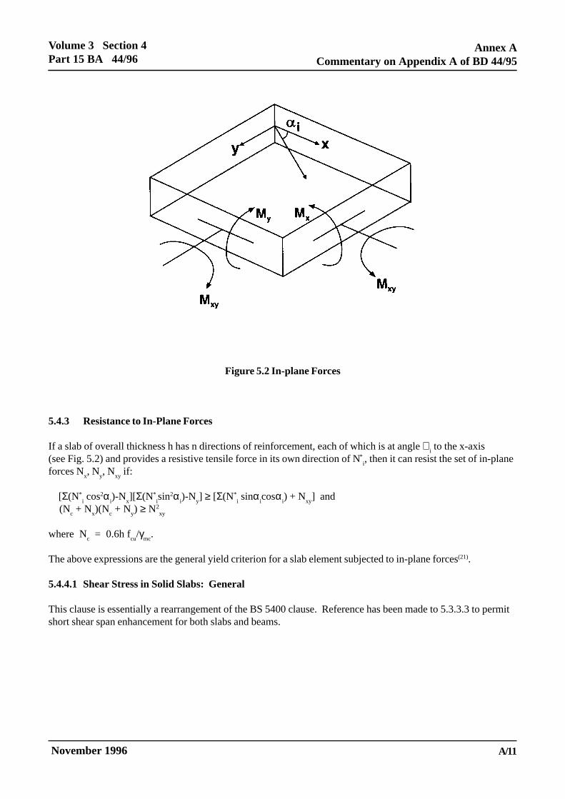
If a slab has n directions of reinforcement in a face, each of which is at angle ∝i to the x-axis (see Fig.5.2) and
provides a moment of resistance M*i in its own direction, then it can resist the set of bending moments M
x and
My, and the twisting moment, M
xy, if:
Σ|[M*i cos2α
i)-M
x][Σ(M*
i sin2α
i)-M
y]| ≥ [Σ(M*
i sinα
icosα
i) + M
xy]2
The above expression is the general yield criterion for a slab element(20). It is emphasised that the numericalvalues of M
i* should be taken as positive for bottom (sagging) reinforcement, and negative for top (hogging)
reinforcement. The well known Wood-Armer design equations are derived from this expression.
November 1996
Volume 3 Section 4Part 15 BA 44/96
Annex ACommentary on Appendix A of BD 44/95
A/11ELECTRONIC COPY NOT FOR USE OUTSIDE THE AGENCY.
PAPER COPIES OF THIS ELECTRONIC DOCUMENT ARE UNCONTROLLED
Figure 5.2 In-plane Forces
5.4.3 Resistance to In-Plane Forces
If a slab of overall thickness h has n directions of reinforcement, each of which is at angle ∝i to the x-axis
(see Fig. 5.2) and provides a resistive tensile force in its own direction of N*i, then it can resist the set of in-plane
forces Nx, N
y, N
xy if:
[Σ(N*i cos2α
i)-N
x][Σ(N*
isin2α
i)-N
y] ≥ [Σ(N*
i sinα
icosα
i) + N
xy] and
(Nc + N
x)(N
c + N
y) ≥ N2
xy
where Nc = 0.6h f
cu/γ
mc.
The above expressions are the general yield criterion for a slab element subjected to in-plane forces(21).
5.4.4.1 Shear Stress in Solid Slabs: General
This clause is essentially a rearrangement of the BS 5400 clause. Reference has been made to 5.3.3.3 to permitshort shear span enhancement for both slabs and beams.

Annex ACommentary on Appendix A of BD 44/95
Volume 3 Section 4Part 15 BA 44/96
November 1996A/12ELECTRONIC COPY NOT FOR USE OUTSIDE THE AGENCY.
PAPER COPIES OF THIS ELECTRONIC DOCUMENT ARE UNCONTROLLED
5.4.4.2 Shear Stresses in Solid Slabs Under Concentrated Loads (Including Wheel Loads).
This clause is essentially a rearrangement of the BS 5400 clause. However, all shear reinforcement within thecritical perimeter is considered effective.
The upper limit on fyv
have been increased to 480 N/mm2 (see 5.3.3.2 comment).
Enhancement of vc has been permitted for short shear spans.
The capacity reduction factor of 0.8 in Fig. 5A (b) and (c)(i) was introduced into building codes to allow formoment transfer at edge and corner columns(31).
5.4.4.3 Shear in Voided Slabs
The longitudinal shear resistance of a circular voided slab may be calculated in accordance with the formulaebelow provided that the following criteria are met:
i. φ/b shall not be greater than 0.7 where φ is the diameter of the void and b is the distance between voidcentres.
ii. φ/h shall not be greater than 0.65 where h is the overall depth of the slab.
iii. The thickness of the compression flange shall not be less than 0.4(h-φ).
The shear capacity of a circular voided slab, Vcv
, shall be derived from:
V KVcv c= ′ where
Vc′ is the shear resistance of the solid slab ignoring the presence of voids, calculated in accordance with
BD44.
K is a variable reduction factor based on the structure’s geometry and shall be taken as:
K = 1 - {0.4(φ/b) + 0.6(φ/b)2.5}.
Voided slab bridge decks which do not comply with the dimensional criteria above or which are found to have aninsufficient shear capacity when assessed in accordance with this Clause, should be referred to the OverseeingOrganisation.
The BS 5400 requirement to include shear due to torsion when checking the flanges has been omitted because thetorsional shear flow in a flange is perpendicular to the flexural shear flow. Alternative methods of checkingflanges for transverse effects, which are based on Vierendeel action, are available(6).
Guidance on the punching of loads through a voided slab as a whole is given in reference(22).
5.5.1.2 Effective Height of a Column
The effective heights in Table 11 relate to idealised situations. In design, an engineer can compare the actualbearing condition with the idealised conditions of Table 11 and choose a conservative effective height. Thisapproach is also applicable to assessment. However, in assessment, it may be necessary to make a moreaccurate estimate of the effective height in order to prove the adequacy of a particular column. The Engineershould then consult specialist literature(23-25).

November 1996
Volume 3 Section 4Part 15 BA 44/96
Annex ACommentary on Appendix A of BD 44/95
A/13ELECTRONIC COPY NOT FOR USE OUTSIDE THE AGENCY.
PAPER COPIES OF THIS ELECTRONIC DOCUMENT ARE UNCONTROLLED
5.5.1.3 Slenderness Limits for Columns
The BS 5400 slenderness limit of le/h of 40 was chosen because it was considered to be a practical upper limit(6).
However, the study of Cranston(26), on which the BS 5400 column clauses are based, included lo/h values of
up to 60. Hence, the latter limit, which was also in BS 5400:Part 4:1978, has been adopted in the assessmentcode. If this slenderness limit is exceeded a full non-linear analysis should be undertaken.
The BS 5400 limit on le/h of 30 for a column not restrained in position at one end is intended to control service
load lateral displacements. It has been omitted from the assessment code which is concerned predominantly withultimate rather than service load behaviour.
5.5.3.1 General (Short Columns)
The nominal eccentricities of BS 5400 may be replaced by the actual eccentricities when they are measured.
5.5.3.2 Analysis of Section
See comment on 5.3.2.1 regarding the enhancement of concrete strength and failure strain arising fromrestraining links or helical binding.
5.5.3.3 Design Charts for Rectangular and Circular Columns
See comment on 5.3.2.2
5.5.4 Short Columns Subject to Axial Load and either Bending about Major Axis or BiaxialBending
See comment on 5.3.3.1.
The expression for ∝n gives the same values as Table 12 of BS 5400. It should be noted that the ∝
n values are
conservative(6). Hence, a column which is apparently inadequate when using Equation 16 could, possibly, beshown to be adequate if assessed in accordance with 5.5.3.2.
The BS 5400 clause states that Equation 16 is also applicable to circular columns. However, a circular columnsubject to biaxial bending can be assessed for the resultant moment about a single axis.
5.5.5.1 General (Slender Columns)
The additional moment approach to allowing for lateral column deflection of 5.5.5.2 to 5.5.5.4 can be veryconservative for certain end restraint conditions(25). Hence, in some cases it may be preferable to carry out a fullnon-linear analysis(25-29).
A circular column subject to biaxial bending can be assessed for the resultant moment about a single axis.
5.5.6 Shear Resistance of Columns
The shear strength enhancement factor to allow for the axial load is that adopted in the ACI Code(30) and is lessconservative than the BS 5400 factor. The requirements for calculating the shear capacity of a circular columnare based on those of the ACI Code.
Annex ACommentary on Appendix A of BD 44/95
Volume 3 Section 4Part 15 BA 44/96
November 1996A/14ELECTRONIC COPY NOT FOR USE OUTSIDE THE AGENCY.
PAPER COPIES OF THIS ELECTRONIC DOCUMENT ARE UNCONTROLLED
5.6.1.2 Limits to Slenderness
See comments on 5.5.1.2 and 5.5.1.3.
5.6.2 Forces and Moments in Reinforced Concrete Walls
See comment on 5.3.3.1.
5.6.4 Slender Reinforced Walls
See comment on 5.5.5.1.
5.6.5 Shear Resistance of Reinforced Walls
See comment on 5.5.6.
5.7.3.1 Resistance to Bending (Bases)
With regard to distributions of reinforcement, the assessment clause is a rearrangement of the BS 5400 designclause.
An alternative method of analysis for a slab base is yield line theory.
5.7.3.2(1) Shear
The short shear span enhancement factor is greater than the BS 5400 value (see comment on 5.3.3.3).
5.7.3.2(2)
The short shear span enhancement factor permitted for punching shear in 5.4.4.2 (see comment on 5.4.4.2) willoften be beneficial when assessing pile caps.
Difficulties can arise in applying 5.4.4.2 and Figure 5A to the assessment of certain pile caps (e.g. circular pilecaps with circumferential and radial bars). It is not possible to give general recommendations to cover all suchsituations, and it is necessary to consider the actual punching shear failure surfaces which could occur. Usefulinformation is given in References 8, 31 and 32.
5.7.3.3 Bond and Anchorage
The local bond clause of BS 5400 is not relevant: see comment on 5.8.6.2.
5.8.1.2 Accuracy of Position of Reinforcement
See comment on 4.3.3.3. Guidance on the measurement of the location of reinforcement by the use ofcovermeters is given in BA 23/86(60).
5.8.2 Concrete Cover to Reinforcement
The BS 5400 covers should, ideally, be present in all structures, although adequate durability may often beachieved with good quality and well compacted concrete with smaller covers. However, the presence of smallercovers suggests that the inspection frequency may need to be increased. If the cover is substantially less than theBS 5400 values bond strength could be reduced(58).
November 1996
Volume 3 Section 4Part 15 BA 44/96
Annex ACommentary on Appendix A of BD 44/95
A/15ELECTRONIC COPY NOT FOR USE OUTSIDE THE AGENCY.
PAPER COPIES OF THIS ELECTRONIC DOCUMENT ARE UNCONTROLLED
5.8.4.1 Minimum Area of Main Reinforcement
The minimum areas of tension reinforcement in a beam or slab specified in BS 5400 are intended to ensure thatthe reinforcement does not yield as soon as cracking occurs, and extremely wide cracks are thereby avoided.This may also be achieved by ensuring that the area of tension reinforcement is not less than 0.167 b
ad(f
t/f
y)(6)
where ft, the flexural tensile strength of the concrete, which may, in the absence of other information, be taken as
0.556 √fcu. The BS 5400 values can be obtained from this expression by assuming a value of 50 N/mm2 for f
cu.
If a section has less reinforcement than the specified minimum it may have adequate strength but could developvery wide cracks. It should therefore be inspected frequently to ensure that it remains durable.
The minimum number of longitudinal bars present in a column should be four in rectangular columns and six incircular columns. The BS 5400 minimum bar diameter of 12mm is intended to ensure a rigid cage forconstruction. This requirement is not relevant to assessment. The BS 5400 minimum steel areas for columnsensure that reinforcement yield does not occur under service load conditions(6). Although it is not considerednecessary to impose a minimum steel area for assessment purposes, the engineer should be aware that highservice load stresses can occur in columns having less than the BS 5400 minimum steel areas.
A wall should not be considered as a reinforced concrete wall unless the percentage of vertical reinforcementprovided is at least 0.4% of the gross cross-sectional area of the concrete. This vertical reinforcement may be inone or two layers. Failure to comply with the requirement of this clause may result in large cracks developing.More frequent inspections should be considered.
5.8.4.2 Minimum area of secondary reinforcement
Extremely wide cracks may develop if the following minimum amounts of reinforcement are not present:
(1) In the predominantly tensile area of a solid slab or wall the minimum area of secondary reinforcement shouldbe not less than that given in the first paragraph of 5.8.4.1.
(2) In beams where the depth of the side face exceeds 600mm longitudinal reinforcement should be presenthaving an area of at least 0.05% of b
td on each face with a spacing not exceeding 300mm, where:
bt
is the breadth of the section;d is the effective depth to tension reinforcement.
(3) In a voided slab the amount of transverse reinforcement, expressed as a percentage of the minimum flangecross-sectional area, should be at least 0.6% in the case of high strength steel and 1% in the case of mild steel.These minimum areas are intended to prevent the first crack from immediately passing through the flangethickness(6) whereas the minimum areas given in 5.8.4.1 merely ensure that the steel will not yield at firstcracking(34).
In a solid slab or wall, the main reinforcement should be considered able to resist compression if the area ofsecondary reinforcement restraining the main reinforcement is at least 0.12% of b
td in the case of high strength
reinforcement and 0.15% of btd in the case of mild steel reinforcement. The diameter of the secondary bars
should not be less than one-quarter of the size of the main bars and the spacing should not exceed 300mm.Failure to comply with the requirements of this clause may result in large cracks developing. More frequentinspections should be considered.
The purpose of the minimum amount of secondary steel in beams and slabs with compression reinforcement is torestrain the latter reinforcement so that its full compressive strength can be developed. When there is lesssecondary reinforcement than the specified minimum, the compressive strength of the bars should be reduced inproportion to the ratio of the actual to specified minimum secondary steel areas.

Annex ACommentary on Appendix A of BD 44/95
Volume 3 Section 4Part 15 BA 44/96
November 1996A/16ELECTRONIC COPY NOT FOR USE OUTSIDE THE AGENCY.
PAPER COPIES OF THIS ELECTRONIC DOCUMENT ARE UNCONTROLLED
The BS 5400 reference to early thermal movement is not relevant to assessment.
See 5.8.4.1 for general comments on the implication of minimum steel areas not being provided.
5.8.4.3 Minimum Area of Links
When, in a beam or column, part or all of the main reinforcement is required to resist compression, links or tiesat least one-quarter the size of the largest compression bar should be present at a maximum spacing of 12 timesthe size of the smallest compression bar.
Links should be so arranged that every corner and alternate bar or group in an outer layer of reinforcement issupported by a link passing round the bar and having an included angle of not more than 135°. All other bars orgroups within a compression zone should be within 150mm of a restrained bar in order to resist compression.These minimum link requirements are intended to ensure restraint of compression bars so that their fullcompressive strength can be developed. When there is less link reinforcement than the specified minimum, thecompressive strength of the bars should be reduced in proportion to the ratio of the actual to specified minimumlink areas.
For circular columns, where the longitudinal reinforcement is located round the periphery of a circle, adequatelateral support is provided by a circular tie passing round the bars or groups. When the percentage ofreinforcement required to resist compression in the compression face of a wall or slab exceeds 1%, links at least6 mm or one-quarter of the size of the largest compression bar, whichever is the greater, should be presentthrough the thickness of the member. The spacing of these links should not exceed twice the member thickness ineither of the two principal directions of the member and be not greater than 16 times the bar size in the directionof the compressive force.
In a beam, the spacing of links should not exceed the effective depth of the beam, nor should the lateral spacingof the individual legs of the links exceed this value. Links should enclose all tension reinforcement. The linkspacing in beams is discussed in the comment on 5.3.3.2.
If the links do not enclose all of the tension reinforcement, then the dowel capacity of the reinforcement notenclosed cannot be relied on and the area of the reinforcement not enclosed should not be included in A
s when
obtaining vc from 5.3.3.2. However, if there are no links, then failure is deemed to occur immediately the shear
stress attains vc, and thus, there is no requirement to maintain the dowel component. It should also be noted that
in the case of a slab or wall, transverse reinforcement outside the main reinforcement can also provide thenecessary restraint to maintain the dowel component.
5.8.5 Maximum Areas of Reinforcement in Members
Maximum steel areas are specified in BS 5400 to ensure that concrete can be placed and compacted easily.These maxima are not directly relevant to assessment. However where the steel areas exceed the BS 5400maxima (4% in beams, slab and walls, and 6% to 10% in columns) the concrete could be poorly compacted andparticular attention should be given to inspection of such sections.
5.8.6.2 Local Bond
Local bond stress is not considered applicable in assessment provided that at both sides of any cross section, theforce in each bar is developed by an appropriate embedment length or other end anchorage(2). Hence onlyanchorage bond need be considered.

November 1996
Volume 3 Section 4Part 15 BA 44/96
Annex ACommentary on Appendix A of BD 44/95
A/17ELECTRONIC COPY NOT FOR USE OUTSIDE THE AGENCY.
PAPER COPIES OF THIS ELECTRONIC DOCUMENT ARE UNCONTROLLED
5.8.6.3 Anchorage Bond
The allowable ultimate anchorage bond stress expression is that given in BS 8110 and gives values almostidentical to the BS 5400 table 15 values. It should be noted that values have been included for fabric.
BS 8110 specifies a partial safety factor on the bond stress of 1.4. This partial safety factor allows forvariations in both concrete strength and in bond strength (when the concrete strength is constant). If the worstcredible concrete strength is used it is reasonable to reduce the partial safety factor (see comment on 4.3.3.3). Ifit is assumed that γ
mb can be expressed as √ (γ
mc γ
mbs), γ
mc allows for the variation in concrete strength and γ
mbs
allows for the variation in bond strength, then with γmc
and γmb
equal to their design values of 1.5 and 1.4,respectively, γ
mbs = 1.31. Hence, if γ
mc is equal to its assessment value of 1.20 when using the worst credible
concrete strength (see 4.3.3.3), γmb
= √ (1.20 x 1.31) = 1.25.
The BS 5400 allowable ultimate anchorage bond stresses in Table 15 are functions of only concrete strength, bartype and whether the bar is in tension or compression. Hence, the bond failure mechanism is grossly simplifiedby BS 5400 because it is assumed that the code’s covers, nominal link requirements and detailing clauses will besatisfied. In an assessment these various clauses are often not satisfied and it may be necessary to expressallowable ultimate anchorage bond stresses in terms of the additional variables of: cover; bar diameter andspacing; quantity and arrangement of restraining reinforcement; lateral pressure applied by external loads orreactions; and location of bar within the member. Further guidance on these aspects can be obtained fromReferences 58, 65-71.
5.8.6.4 Effective perimeter of a Bar or Group of Bars
The multiplier (1.2-0.2N) gives the same values as table 16 or BS 5400. Test data do not appear to be availablefor more than 4 bars in a group.
5.8.6.5 Anchorage of Links
The requirements of 5.8.6.5 ensure that a link is fully anchored. A link which does not satisfy the requirementsmay be considered as partially anchored and, hence, as partially effective in resisting shear and providingrestraint to compression reinforcement. It is not possible to make general recommendations on the degree ofpartial effectiveness, and, thus, each case has to be treated individually and agreed with the relevant OverseeingOrganisations. However, the stress in the link should be limited to the value which would cause a bearing failurein the corner of link when calculated in accordance with 5.8.6.9.
5.8.6.7 Lap Lengths
The minimum lap lengths are those given in BS 8110 and are less conservative than the BS 5400 values.
The enhancement factors of 1.4 and 2.0 should be applied only to the calculated lap lengths of bars in tension.They should therefore not be applied to bars in compression nor to the minimum lap lengths specified inparagraph 1 of clause 5.8.6.7.
5.8.6.8 Hooks and Bends
An additional paragraph has been added to the BS 5400 clause to clarify the anchorage value of hooks and bendswhich do not satisfy the BS 5400 requirements.
Annex ACommentary on Appendix A of BD 44/95
Volume 3 Section 4Part 15 BA 44/96
November 1996A/18ELECTRONIC COPY NOT FOR USE OUTSIDE THE AGENCY.
PAPER COPIES OF THIS ELECTRONIC DOCUMENT ARE UNCONTROLLED
5.8.6.9 Bearing Stress Inside Bends
The allowable bearing stress expression is based on tests by Soroushian(62) which show the BS 5400 requirementto be conservative. The maximum values of l = 3l
i and a
b/ø = 8 represent the limits of the test evidence available.
5.8.7 Curtailment and Anchorage of Reinforcement
The BS 5400 requirements have been retained, with the exception that condition (b) has been made lessconservative. The amended condition (b) is in agreement with test data (36,37). The purpose of the BS 5400conditions (a) to (c) is to guard against a reduction in shear strength at points of bar curtailment caused by thepremature formation of flexural cracks at these points(38).
As an alternative to using the BS 5400 empirical curtailment rules, an assessment may be based on a rigorousanalysis of the forces at the curtailment point for the worst load case. In carrying out such an analysis the actualbending moment distributions need to be considered, and it is also essential to take account of the fact that thetension reinforcement has to resist tensile forces which arise from both the bending moment and the shearforce at the section under consideration (6,39,61,64).
5.8.8.1 Minimum Distance between Bars
Minimum bar spacings are specified in BS 5400 to aid placing and compacting of concrete. These minima arenot directly relevant to assessment. However, in sections where the bar spacings are less than the BS 5400minima, the concrete could be poorly compacted and particular attention should be given to inspection of suchsections.
5.8.8.2 Maximum Distance between Bars in Tension
The main reason for limiting maximum bar spacings in design is to control crack widths. Assessment clause5.8.8.2 is very similar to the BS 5400 clause but has been rearranged as a “crack width calculation” clause. Thegeneral spacing of 300mm and the limit for voided slabs in (d) of the BS 5400 clause have been omitted becausethey are not directly relevant to assessment.
In (b), Equation 26 is not appropriate for calculating crack widths in voided slabs subjected to transversebending. An additional Equation, (26A) has been added for these situations which is based on recent research(34).Similarly, a more appropriate tension stiffening formula has been added (40,41).
The approaches given in (c) are conservative. A more accurate method is to base calculations on the strains dueto the combined global and local effects.
5.8.9 Shrinkage and Temperature Reinforcement
The BS 5400 clause requirements, which have been supplemented by BD 28 (DMRB 1.3),(63) are intended tocontrol early thermal cracking. Such cracking is irrelevant to assessment because it occurs a few days afterpouring. However, restrained members having less reinforcement that required by BD 28 (DMRB 1.3) are likelyto exhibit wide early thermal cracks.

November 1996
Volume 3 Section 4Part 15 BA 44/96
Annex ACommentary on Appendix A of BD 44/95
A/19ELECTRONIC COPY NOT FOR USE OUTSIDE THE AGENCY.
PAPER COPIES OF THIS ELECTRONIC DOCUMENT ARE UNCONTROLLED
5.8.10 Arrangement of reinforcement in Skew Slabs
Many existing skew slab bridges have very small amounts of transverse reinforcement compared with theamounts required to comply with current design standards. However, a small amount of transversereinforcement does not necessarily imply that the bridge is inadequate. Yield line theory can often be used todemonstrate that such a bridge has adequate strength, although such decks may suffer from serviceabilityproblems due to premature yielding of the transverse reinforcement, and may warrant more frequent inspectionand maintenance.
In using yield line theory it is not always possible to state in advance which will be the critical collapsemechanism, particularly for continuous decks. Hence, the assessing engineer will need to consult specialistliterature.
5.9.2 Durability (Lightweight Aggregate) See comment on 5.8.2.
5.9.4 Shear Resistance of Beams
BS 5400 applies a reduction factor of 0.8 to vc for lightweight aggregate concrete. The higher values are
consistent with test data(42).
5.9.10 Local Bond, Anchorage Bond and Laps
See comment on 5.8.6.2 regarding local bond. Anchorage bond stresses for mild steel bars embedded inlightweight aggregate concrete have been increased from 50% to 80% of those for normal weight aggregateconcrete.(2)
Annex ACommentary on Appendix A of BD 44/95
Volume 3 Section 4Part 15 BA 44/96
November 1996A/20ELECTRONIC COPY NOT FOR USE OUTSIDE THE AGENCY.
PAPER COPIES OF THIS ELECTRONIC DOCUMENT ARE UNCONTROLLED
6. ASSESSMENT: PRESTRESSED CONCRETE
6.1.1 Introduction
No references are made to Classes 1, 2 and 3 prestressed concrete since these Classes relate to criteria at theserviceability limit state. If an assessment under service load conditions is required, the relevant Organisationwill specify the criteria (see clause 4.1.1 and its comment).
Grouted duct post-tensioning has exhibited tendon corrosion associated with the ingress of de-icing salts throughinadequately grouted ducts. When inadequately grouted ducts or tendon corrosion are encountered in anassessment, the rules for prestressed concrete should be modified by taking into account the following:i) Local failure of wires or strands may occur when the tendon strength is reduced to the prestressing force.Hence, wires which have suffered sectional loss which has resulted in them being unable to sustain their prestressforce, (typically a 40% section loss), should be considered ineffective. The strength of a section at the ultimatelimit state should be based on the remaining cross-sectional area of the effective wires only.ii) Tendons, strands or wires which are ineffective locally can re-anchor and become fully effective elsewhere.The anchorage length will depend on the quality of the grouting in the ducts. Where the grouting is good andwhere nominal links to BS 5400 are provided, the re-anchorage length may be taken as the transmission lengthgiven in Cl 6.7.4 multiplied by the square root of the number of strands in the tendon.iii) Where there is evidence of extensive inadequate grouting or where the BS5400 minimum link requirement isnot met, assessments which depend on re-anchorage of tendons should not be undertaken without specialinvestigation. Where in the opinion of the engineer the grouting is too poor to allow re-anchorage of tendons, themember should be treated as unbonded and assessed accordingly.iv) In assessing the strength of a structure with corroded tendons, allowance should be made of possible futuredeterioration until the next Principal Inspection.
Further guidance in assessing structures with tendon corrosion is given in BA 51, The Assessment of ConcreteStructures Affected by Steel Corrosion (DMRB 3.4.13).
If the extent of tendon corrosion cannot be directly measured by observing damage to steel, overall levels ofprestress in a member can be determined from concrete stress measurements. Before adopting this approach, theagreement of the relevant Overseeing Organisation should be obtained. Specialist advice should also be sought.As there is a possibility of significant errors in determining the level of prestress, spot checks on levels ofremaining prestress in individual tendons should also be made. In calculations, it will always be necessary toassume a value of effective prestress to a greater accuracy than is actually known. Calculations should thereforebe performed using an upper and lower bound to the estimated effective prestress. In practice, the lower boundwill normally be critical for assessments. Having estimated the effective level of prestress in a structure, theflexural, shear and torsional strength can be assessed using BD 44 (DMRB 3.4.14). If the grouting to the ducts isextremely poor, the tendons may have to be treated as unbonded.
When assessing a prestressed concrete bridge incorporating unbonded tendons, external tendons or lightweightaggregate concrete assessment criteria should be agreed with the relevant Overseeing Organisation. BD 58(DMRB 1.3.9) and BA 58 (DMRB 1.3.10), The Design of Concrete Highway Bridges and Structures withExternal and Unbonded Prestressing, may be used for the assessment of structures with external or unbondedtendons. Alternatively, with the agreement of the Overseeing Organisation, specialist literature on these topicsmay be used. The engineer is referred to: Reference 43 for unbonded tendons; Reference 44 for external tendons;and Reference 45 for lightweight aggregate concrete.

November 1996
Volume 3 Section 4Part 15 BA 44/96
Annex ACommentary on Appendix A of BD 44/95
A/21ELECTRONIC COPY NOT FOR USE OUTSIDE THE AGENCY.
PAPER COPIES OF THIS ELECTRONIC DOCUMENT ARE UNCONTROLLED
6.1.2.2 Durability
See comment on 5.1.2.2
6.1.4 Strength of Materials
See comment on 2.1.3.1
6.1.4.2 Strength of Concrete
See comment on 5.1.4.2.
6.1.4.3 Strength of Prestressing Tendons
For structures designed to codes prior to the adoption of the term characteristic strength, the tendon strength wasspecified in terms of minimum ultimate strength. For the purpose of assessment, the characteristic strength oftendons may be taken as the minimum ultimate strength.
6.2.2 Redistribution of Moments
Item (2) of condition (a) is conservative for current U.K. tendons. However, it is not necessarily conservative fornon-current U.K. tendons nor for non-U.K. tendons. For such tendons, information should be obtained on thetendon’s ductility from past records. See also comment on 5.2.2.
6.3.2 Serviceability Limit State: Flexure
See comment on 4.1.1.
6.3.3.1 Section Analysis (Ultimate Limit State)
See comment on 5.3.2.1.
6.3.3.2 Design Charts
See comment on 5.3.2.2, and treat fpu
in the same way as fy.
6.3.3.3 Assessment Formula
The tabulated values of fpb
and x given in table 27 of BS 5400 have been replaced by two equations which givethe same numerical values as table 27 when the BS 5400 design values of γ
mc and γ
ms are adopted.
6.3.4.1 General (Shear Resistance of Beams)
The limit on the shear resistance is related to the area of longitudinal reinforcement in excess of that required toresist bending. See 5.3.3.2.
The assessment clause state that Vc may be taken as V
co when the applied moment does not exceed M
cr. This is
because the section will not be flexurally cracked and, hence, the Vcr calculation is not appropriate.
When using the reinforced concrete clause (5.3.3) within the transmission zone, the area of bar tendons (e.g.Macalloy or Dividag bars) may be included in A
s, because their rigidity enables them to contribute to the shear
resistance component due to dowel action.
Annex ACommentary on Appendix A of BD 44/95
Volume 3 Section 4Part 15 BA 44/96
November 1996A/22ELECTRONIC COPY NOT FOR USE OUTSIDE THE AGENCY.
PAPER COPIES OF THIS ELECTRONIC DOCUMENT ARE UNCONTROLLED
6.3.4.2 Sections Uncracked in Flexure
In view of the change in 6.3.4.1, which requires Vcr to be considered only for cracked sections, the equation for
the cracking moment has been included in 6.3.4.2.
The terms 0.49 √(fcu/γ
mc) and 0.32 √(f
cu/γ
mc) replace the BS 5400 terms 0.37 √f
cu and 0.24 √f
cu, respectively. The
latter values include a partial safety factor of 1.5 applied to fcu
, which has been replaced in the assessment codeby the general value, γ
mc. The BS 5400 values also include an additional safety factor of 1.25 to allow for
strength reductions caused by shrinkage cracking, repeated loading and variations in concrete quality46. Thisfactor has been reduced to 1.15 in the assessment code because variations in concrete quality are allowed forin γ
mc.
It should be noted that, for flanged beams, Equation 28 is an approximation(6). For such beams it may bepreferable to work from first principles.
6.3.4.3 Sections Cracked in Flexure
BS 5400 gives different design equations for classes 1 and 2 (Equation 29) and class 3 (Equation 30). However,it is actually the f
pe/f
pu ratio which determines which equation should be used(47).
Since no reference is made in the assessment code to classes of prestressed concrete the criterion for selectingEquation 29A or 30A has been made on the basis of the f
pe/f
pu ratio.
The BS 5400 Equation 29 and the lower limiting values for Vcr contain a partial safety factor of 1.5 applied to
fcu. The equivalent terms in the assessment code have been modified and f
cu replaced by f
cu/γ
mc.
Equations 29 and 30 have been further modified by including the d/2 term. This term was conservatively omittedfrom the BS 5400 equations(47).
Although it is illogical to ignore the vertical component of inclined tendons in cracked sections, there areinsufficient test data to justify its inclusion.
6.3.4.4 Shear Reinforcement
Most of the comments on clause 5.3.3.2 are also applicable to 6.3.4.4. In particular the last paragraph of 5.3.3.2regarding the absence and effectiveness of shear reinforcement is applicable to prestressed concrete as well asreinforced concrete.
The BS 5400 clause 6.3.4.4 requires the link spacing to be reduced when the shear force is large. Thisrequirement has been omitted from the assessment code because there is no logical reason to justify its inclusion.It is understood that the requirement to limit the link spacing to four times the web thickness is related to webbuckling. If the web cannot buckle (because, for example, it is surrounded by in-situ infill concrete) then thisspacing requirement may be relaxed.
The requirement to relate shear capacity to the area of longitudinal reinforcement or prestressing steel has beenmoved to 6.3.4.1 (see first paragraph of the comment on 6.3.4.1).
The expression for Vs is not valid for a link spacing in excess of d
t. In such cases an analysis has to be
preformed which considers various possible shear failure planes.
The requirement to limit spacing to four times the web thickness is considered to be related to web stability offlanged beams. Where greater link spacings occur, it is advisable to ignore the V
s term and/or carry out non-
linear analysis of the web.
November 1996
Volume 3 Section 4Part 15 BA 44/96
Annex ACommentary on Appendix A of BD 44/95
A/23ELECTRONIC COPY NOT FOR USE OUTSIDE THE AGENCY.
PAPER COPIES OF THIS ELECTRONIC DOCUMENT ARE UNCONTROLLED
6.3.4.5 Maximum Shear Force
Table 28 of BS 5400 has been replaced by an expression which gives very nearly the same values. See also thecomment on 5.3.3.1.
6.3.5.2 Stresses and Reinforcement (Torsion)
The prestressing steel stresses given in BS 5400 are really stress increments(6). In the assessment code they havebeen replaced by total stresses, in line with the latest version of BS 5400: Part 4.
The BS 5400 increase in vtu for concrete grades above 40 is already allowed for in the expression for v
tu (see
comment on 5.3.4.3).
6.3.5.4 Other Assessment Methods
This clause permits the consideration of strength at various points rather than the consideration of cross-sectionalstrength. Possible methods for box girders are presented by Swan and Williams(48) and Maisel and Swan(49).
6.3.6 Longitudinal Shear
See comment on 5.3.5.
6.3.7 Deflection of Beams
The deflection of a beam which is uncracked under the assessment service load may be determined using anelastic analysis based on the concrete section properties and a modulus of elasticity which allows for creep, ifappropriate.
Beams with low levels of prestress may be cracked under the assessment service load. The deflections of suchbeams may be determined using moment curvature relationships(50).
6.4 Slabs
See comment on 6.3.4.2 for the explanation of the ft expression.
6.7.2.4 Loss of Prestress due to Shrinkage of the Concrete
The age factors of BS 5400 are not considered relevant to assessment.
6.7.2.5 Loss of Prestress due to Creep of the Concrete
The age factors of BS 5400 are not considered relevant to assessment.
6.7.3.2 Friction in the Jack and Anchorage
Jacks are generally calibrated to give a specified force at the duct side of the anchorage. Hence, the friction lossin the jack and anchorage should not be of concern in assessment.

Annex ACommentary on Appendix A of BD 44/95
Volume 3 Section 4Part 15 BA 44/96
November 1996A/24ELECTRONIC COPY NOT FOR USE OUTSIDE THE AGENCY.
PAPER COPIES OF THIS ELECTRONIC DOCUMENT ARE UNCONTROLLED
6.7.4 Transmission Length in Pre-Tensioned Members
It is emphasised that data are not available on transmission lengths in weak concretes less than 28 N/mm2.Hence, caution is advised if the concrete has deteriorated below 28 N/mm2, even if the strength at transfer was inexcess of this value.
6.7.5 End Blocks
Tendon jacking loads which have to be considered in end block design are not relevant to assessment.The equation for F
bst gives the same values as Table 30 of BS 5400.
The restriction on the stress in anti-bursting reinforcement to that corresponding to a strain of 0.001 in BS 5400is a serviceability criterion which has been omitted in the assessment code.
Detailed information on end block strength is given in Reference 52, whilst Reference 53 deals with end blocks inwhich the concrete is assumed to resist tension.
6.8.2.1 General (Cover to Prestressing Tendons)
See comment on 5.8.2.
6.8.3.3 Tendons in Ducts
The BS 5400 clause is not considered to be relevant to assessment except for curved ducts.

November 1996
Volume 3 Section 4Part 15 BA 44/96
Annex ACommentary on Appendix A of BD 44/95
A/25ELECTRONIC COPY NOT FOR USE OUTSIDE THE AGENCY.
PAPER COPIES OF THIS ELECTRONIC DOCUMENT ARE UNCONTROLLED
7. ASSESSMENT: PRECAST, COMPOSITE AND PLAIN CONCRETE CONSTRUCTION
7.1.2.3 Connections and Joints
No reference is made to movement joints in the assessment code. However, it should be remembered that thelack of adequate joints can lead to concentrated cracking.
7.2.2 - Other Precast Members
The BS 5400 reference to precast components is not relevant to assessment.
7.2.3.1 - Concrete Corbels
Specialist literature(16,54) should be consulted when the depth at the outer edge of the bearing is less than one-halfof the depth at the face of the supporting member. The limiting value of a
v/d for a corbel has been extended from
the value of 0.6 in BS 5400 to 1.0 in the assessment code. The latter value is within the range of applicability ofthe assessment method according to Somerville(16).
The BS 5400 minimum main steel percentage has been omitted since it is a serviceability requirement to preventthe rapid opening of cracks after initial cracking(54). However, it should be noted that wide cracks are likely tooccur if the main steel percentage is less than 0.4%.
BS 5400 requires the bearing area not to project beyond the straight portion of the main bars in order to preventthe cover concrete being sheared off. When assessing a corbel where such a projection does occur, theproportion of the bearing area which projects beyond the straight portion of the main bars should be ignored inall strength calculations.
The BS 5400 requirement for minimum horizontal links is to ensure a ductile failure and to control the widths ofdiagonal cracks. These criteria are not considered relevant to assessment and, thus, the minimum requirementhas been omitted in the assessment code. However, the assessing Engineer should be aware that the absence ofhorizontal links could result in wide cracks and/or a brittle failure.
The BS 5400 requirement for a serviceability check is not considered relevant to assessment, unless specificallyrequested by the Overseeing Organisation.
7.2.3.3 Bearing Stresses
The allowable bearing stresses are higher than the BS 5400 values. However the bearing stress expression isthat given in BS 8110 and is based on the latest CEB Formula(35).
The definition of Asup
has been modified to agree with the latest version of BS 5400: Part 4.
7.2.4.2 Halving Joint
The assessment clause dealing with half joints is more general than the BS 5400 clause in that it permits twostrut and tie systems to be assessed and the load capacities of the two systems added. This approach has beenshown to predict adequately failure loads(55).
The BS 5400 requirement to limit the shear stress to 4vc, with v
c calculated for the full beam section, was
intended to prevent over-reinforcement of the joint and, hence, to ensure a ductile failure. It is more logical, interms of shear capacity, to adopt the maximum allowable shear stress given in 5.3.3.1.
Annex ACommentary on Appendix A of BD 44/95
Volume 3 Section 4Part 15 BA 44/96
November 1996A/26ELECTRONIC COPY NOT FOR USE OUTSIDE THE AGENCY.
PAPER COPIES OF THIS ELECTRONIC DOCUMENT ARE UNCONTROLLED
BA 39, The assessment of Reinforced Concrete Half-Joints, (DMRB 3.4.6) gives guidance on the assessment ofhalf-joints at both the ultimate and serviceability limit states. As half-joints are prone to durability problems, itis advisable to check them at the serviceability limit state.
7.3.2.2 Sleeving
This clause has been abbreviated from BS 5400 clause, because it is envisaged that test data appropriate to theactual condition of use would be obtained.
7.3.2.3 Threading
See comment on 7.3.2.2.
7.3.2.4 Welding of Bars
The BS 5400 clause is assumed to refer to the locations of welded connections and is, thus, not relevant toassessment.
7.3.3 Other Types of Connections
The BS 5400 references to resin mortar and cement mortar joints are relevant only to construction and theserviceability limit state, and have, thus, been omitted from the assessment code.
They also preclude tension or shear transfer at a joint, whereas, generally, it is possible for such a joint to resistsome tension and/or shear. Hence, it is suggested that the assessment of such joints should be based on relevanttest data.
7.4.2.2 Vertical Shear
The BD 44 (DMRB 3.4.14) rules for shear in infill concrete decks are conservative as they do not allow forredistribution of shear between the in-situ and precast sections. Tests currently being undertaken indicate that theshear capacity of an infill concrete deck can be taken as the sum of the infill concrete section, V
i, and the precast
concrete section, Vp.
7.4.2.3 Longitudinal Shear
Fig. 8A is reproduced from the latest version of BS 5400.
The BS 5400 design values of k1 implicity allow for a partial safety factor of 1.6. Hence, the assessment
characteristic values are 1.6 times the BS 5400 design values, and the partial safety factor, γms
, is included inexpression (a).
Test data(56) have shown that the BS 5400 design values of v1 implicity allow for partial safety factors of 1.25,
1.6 and 2.0 for type 2, type 1 and monolithic surfaces, respectively. Furthermore, the values for monolithicconcrete have been shown to be less dependent on concrete strength than implied by BS 5400. Hence, theassessment characteristic values have been obtained as follows.
Monolithic
Design values suggested by Hughes(56) have been incorporated in a slightly amended form in the latest version ofBS 5400: Part 4. These values incorporate a partial safety factor of 1.25 and have thus been multiplied by 1.25to give the characteristic values for assessment.
November 1996
Volume 3 Section 4Part 15 BA 44/96
Annex ACommentary on Appendix A of BD 44/95
A/27ELECTRONIC COPY NOT FOR USE OUTSIDE THE AGENCY.
PAPER COPIES OF THIS ELECTRONIC DOCUMENT ARE UNCONTROLLED
Surface type 1 BS 5400 values multiplied by 1.6.
Surface Type 2 BS 5400 values multiplied by 1.25.
The partial safety factor for shear, γmv
, (see 5.3.3.2) is applied to the characteristic v1 values(56).
The steel stress definition has been modified to permit partially anchored reinforcement to contribute to thelongitudinal shear capacity.
The factor 0.8 in expression (b) reduces to the BS 5400 value of 0.7 when the BS 5400 value of γms
of 1.15 isapplied.
The BS 5400 minimum steel requirement of 0.15% has not been included because its origin is unclear. However,one should be aware that brittle longitudinal shear failures can occur with small amounts of reinforcement(56).Furthermore, in Reference 56 it is observed that the stirrups act as ties across the interface. If the form ofconstruction consists of a slab cast on to the top of beams with no reinforcement crossing the interface then therewill be nothing to provide a tie if the tensile resistance of the concrete across the interface is destroyed by theeffects of repeated loading. In such a case, it would be prudent not to treat the member as acting compositely.However, if the in-situ slab encases the top flange of the beam then mechanical interlock between the precast andin-situ concretes may provide adequate tie action and the interface shear strength could be based on the concreteinterface shear resistance above.
The reason for the maximum steel spacing requirement in BS 5400 is also unclear. Hence, one should applyengineering judgement when considering this requirement and not automatically ignore reinforcement spaced atcentres greater than the specified maximum. Some relevant data have been obtained in tests on PCDG T2 beamsat TRRL. These beams behaved satisfactorily with links spaces at seven times the slab thickness, and there wereindications that the 600mm limit on spacing was conservative.
7.4.3 Serviceability Limit State
If a serviceability limit state assessment is required by the relevant Overseeing Organisation, the following pointsshould be considered:a. There appears to be no test data to quantify the permissible enhancement in allowable compressive stress
in 7.4.3.2 of BS 5400. However, for the case of a fully restrained flange, BS 8110 permits anenhancement of up to 50%(57).
b. The allowable flexural tensile stresses in table 32 of BS 5400 are very conservative and include a partialsafety factor of about 2.5 on the lower bound to the experimental evidence(6). For assessment, thesestresses may be increased by multiplying by a factor not exceeding 2.5. However in such circumstances,the 50% increase permitted in 7.4.3.3 of BS 5400 should not be applied.
7.5.1 General (Plain Concrete Walls and Abutments)
BS 5400 restricts its application to braced plain concrete walls with a slenderness ratio not exceeding 5, since itis considered that this ratio reflects current practice. When assessing an unbraced and/or a more slender wall,the engineer should consult clause 3.9.4 of BS 8110 which deals with unbraced and slender walls. In applyingthe latter clause for assessment purposes, the following modification should be made: replace the constant 0.3 inequations 43 to 46 of BS 8110 with (0.675/γ
mcw).
Annex ACommentary on Appendix A of BD 44/95
Volume 3 Section 4Part 15 BA 44/96
November 1996A/28ELECTRONIC COPY NOT FOR USE OUTSIDE THE AGENCY.
PAPER COPIES OF THIS ELECTRONIC DOCUMENT ARE UNCONTROLLED
7.5.5 Analysis of Section
The factor λw in BS 5400 and CP 110 has been replaced with a constant value of 0.3 in BS 8110. The latter
value includes (57) an allowance for a partial safety factor of 2.25. Hence, in the assessment code, the factor 0.3is replaced with (0.3 x 2.25/γ
mcw) where γ
mcw is either 2.25 (for use with the characteristic strength) or
2.25 x 1.2/1.5 = 1.80 (for use with the worst credible strength).
7.5.6 Shear
The background to this clause, which originated in CP 110, is unclear. In particular the value of the inherentpartial safety factor is not known. Hence, the shear stresses should be considered as assessment values and nopartial safety factor applied to them.
7.5.9 Shrinkage and Temperature Reinforcement
See comment on 5.8.9.
November 1996
Volume 3 Section 4Part 15 BA 44/96
Annex ACommentary on Appendix A of BD 44/95
A/29ELECTRONIC COPY NOT FOR USE OUTSIDE THE AGENCY.
PAPER COPIES OF THIS ELECTRONIC DOCUMENT ARE UNCONTROLLED
REFERENCES
1. INSTITUTION OF STRUCTURAL ENGINEERS. Appraisal of existing structures. July 1980, pp.
2. BRITISH STANDARDS INSTITUTION. BS 8110: Part 2: 1985. Structural use of concrete. Part 2.Code of practice for special circumstances.
3. THE CONCRETE SOCIETY. Concrete core testing for strength. Technical Report No. 11, 1987.
4. BRITISH STANDARDS INSTITUTION. BS 6089: 1981. Guide to assessment of concrete strength inexisting structures, pp.11.
5. CLARK, L.A. Elastic analysis of concrete bridges and the ultimate limit state. The Highway Engineer,October 1977, pp. 22-24.
6. CLARK, L.A. Concrete bridge design to BS 5400. Construction Press. 1983. pp. 186. (IncludingSupplement incorporating 1984 Revisions, 1985, pp. 31)
7. COPE, R. J. and RAO, P. V. A two-stage procedure for the non-linear analysis of slab bridges.Proceedings of the Institution of Civil Engineers, Vol. 75, Part 2, December 1983, pp. 671-688.
8. COPE, R.J. and CLARK, L. A. Concrete slabs: analysis and design. Elsevier Applied Science, 1984.pp. 507.
9. SIVIERO, E. Rotation capacity of monodimensional members in structural concrete. IstitutoUniversitario di Architettura di Venezia, Instituto di Scienza delle Construzioni, 1973, pp. 17.
10. MARSHALL, W. T. A survey of the problems of lateral instability in reinforced concrete beams.Proceedings of the Institution of Civil Engineers, Vol. 43, July 1969, pp. 397-406.
11. CLARKE, J, L. and TAYLOR, H. P. J. Web crushing - a review of research. Cement and ConcreteAssociation, Technical Report 42.509, August 1975, pp. 16.
12. PEDERSON, C. Shear in beams with bent-up bars. Final Report of the International Association forBridge and Structural Engineering Colloquium on Plasticity in Reinforced Concrete, Copenhagen, 1979,pp. 79-86.
13. CORGI, J. L. Shear capacity of high strength concrete beams. Concrete, Vol. 21, No. 3, March 1987,pp. 24-26.
14. SHEAR STUDY GROUP. The shear strength of reinforced concrete beams. Institution of StructuralEngineers, London, 1969, pp. 170.
15. BAKER, A. L. L, YU. C. W. and REGAN, P. E. Explanatory note on the proposed Unified Code Clauseon shear in reinforced concrete beams with special reference to the Report of the Shear Study Group. TheStructural Engineer, Vol 47, No. 7 July 1969, pp. 285 - 293.
16. SOMERVILLE, G. The behaviour and design of reinforced concrete corbels. Cement and ConcreteAssociation, Technical Report 42.472, August 1972, pp. 12.

Annex ACommentary on Appendix A of BD 44/95
Volume 3 Section 4Part 15 BA 44/96
November 1996A/30ELECTRONIC COPY NOT FOR USE OUTSIDE THE AGENCY.
PAPER COPIES OF THIS ELECTRONIC DOCUMENT ARE UNCONTROLLED
17. AMERICAN CONCRETE INSTITUTE COMMITTEE 438. Tentative recommendations for the designof reinforced concrete members to resist torsion. Proceedings of the American Concrete Institute, Vol. 66,No. 1, January 1969, pp. 1-8.
18. SWAN, R. A. The effect of size on the torsional strength of rectangular reinforced concrete beams.Cement and Concrete Association, Technical Report 42.453, March 1971, pp. 8.
19. LAMPERT, P. Torsion and bending in reinforced and prestressed concrete members. Proceedings of theInstitution of Civil Engineers, Vol. 50, December 1971, pp. 487-505.
20. KEMP, K. O. The yield criterion for orthotropically reinforced concrete slabs. International Journal ofMechanical Sciences, Vol. 7, 1965, pp. 737-746.
21. NIELSEN, M. P. Limit analysis and concrete plasticity. Prentice-Hall, 1984, pp. 420.
22. CLARK, L. A. and THOROGOOD, P. Flexural and punching shear strengths of concrete beams andslabs. Transport and Road Research Laboratory, Contractor Report 60, 1987, pp. 33.
23. LEE, D. J. The theory and practice of bearings and expansion joints for bridges. Cement and ConcreteAssociation, Publication 12.036, 1971, pp. 65.
24. TIMOSHENKO, S. P. Theory of elastic stability. McGraw-Hill Book Co., New York and London, 1936,pp. 518.
25. JACKSON, P. A. Slender bridge piers and the effective height provisions of BS 5400: Part 4. Cementand Concrete Association, Technical Report 42.461, June 1985, pp. 18.
26. CRANSTON, W. B. Analysis and design of reinforced concrete columns. Cement and ConcreteAssociation, Research Report 41.020, 1972, pp. 54.
27. CRANSTON, W. B. A computer method for the analysis of restrained columns. Cement and ConcreteAssociation, Technical Report 42.402, April 1967, pp. 20.
28. MENEGOTTO, M. and PINTO, P. E. Slender RC compressed members in biaxial bending. Proceedingsof the American Society of Civil Engineers, Vol. 103, No. ST3, March 1977, pp. 587-605.
29. CANSTON, W. B. Computer analysis of columns. Instability and plastic collapse of steel structures,Proceedings of The Michael R. Horne Conference. Editor: L. J. Morris. St. Albans, Granada PublishingLtd., 1983, pp, 243-252.
30. AMERICAN CONCRETE INSTITUTE. Building code requirements for reinforced concrete (ACI 318-83), 1983, pp. 111.
31. REGAN, P. E. Behaviour of reinforced concrete flat slabs. Construction Industry Research andInformation Association Report 89, London 1981, pp. 89.
32. REGAN, P. E. and BRAESTRUP, M. W. Punching shear in reinforced concrete. CEB Bulletin No. 168,January 1985, pp. 232.
33. BEEBY, A. W. Short term deformations of reinforced concrete members. Cement and ConcreteAssociation, Technical Report 42.408, March 1968, pp. 32.
November 1996
Volume 3 Section 4Part 15 BA 44/96
Annex ACommentary on Appendix A of BD 44/95
A/31ELECTRONIC COPY NOT FOR USE OUTSIDE THE AGENCY.
PAPER COPIES OF THIS ELECTRONIC DOCUMENT ARE UNCONTROLLED
34. ODUYEMI, T. O. S. and CLARK, L. A. Prediction of crack widths in circular-voided reinforcedconcrete slabs subjects to transverse bending. Magazine of Concrete Research, Vol. 39, No. 140,September 1987, pp. 124-132.
35. ROWE, R. E. et all. Handbook to British Standard BS 8110: 1985. The Structural Use of Concrete.Palladian Publications Ltd., 1987, pp. 206.
36. FERGUSON, P. M./ and MATLOOB, F. N. Effect of bar cut-off on bond and shear strength of reinforcedconcrete beams. Proceedings of the American Concrete Institute, Vol. 56, No. 1, July 1959, pp. 5-24.
37. REGAN, P. E. and MITRA, A. C. Curtailment of main reinforcing steel and its effects on shear. TheStructural Engineer, Vol. 50, No. 11, November 1972, pp. 445-449.
38. BATE, S. C. C. et al. Handbook on the Unified Code for structural concrete. London, Cement andConcrete Association, 1972, pp. 153.
39. CLARK, L. A. Longitudinal shear reinforcement in beams. Concrete, Vol. 18, No. 2, February 1984,pp. 22-23.
40. ODUYEMI, T. O. S. and CLARK, L. A. Tension stiffening in transverse sections of circular-voidedconcrete slabs. Magazine of Concrete Research, Vol. 39. No. 138, March 1987, pp. 35.41.
41. ODUYEMI. T. O. S. Stiffnesses and cracking of voided slab bridges. PhD. Thesis, University ofBirmingham, September 1986.
42. CLARKE J. L. Shear strength of lightweight aggregate concrete. Concrete, Vol. 21, No. 4, April 1987,pp. 12-13.
43. ANDREW, A. E. Unbonded tendons in post-tensioned construction. Thomas Telford. 1987.
44. VIRLOGEUX, M. External prestressing of concrete. FIP Notes, 1987/2, pp. 16-20.
45. SWAMY, R. N. Prestressed lightweight concrete. Developments in prestressed Concrete - 1, Sawko, F.(Ed.) applied Science Publishers, 1978, pp. 149-191.
46. HAWKINS, N.M. The shear provision of AS CA35-SAA Code for prestressed concrete. CivilEngineering Transactions, Institute of Engineers, Australia, Vol. CE6, September 1964, pp. 103-116.
47. REYNOLDS, G. C., CLARKE, J. L. and TAYLOR, H. P. J. Shear provisions for prestressed concrete inthe Unified Code, CP 110:1972. Cement and Concrete Association, Technical Report 42.500, October1974. pp. 16.
48. SWAN, R. A. and WILLIAMS, A. Combined loading tests on model prestressed concrete box beams withsteel mesh. Cement and Concrete Association, Technical Report 42.485, October 1973, pp. 43.
49. MAISEL, B. I. and SWAN, R. A. The design of concrete box spine-beam bridges. Construction IndustryResearch and Information Association, Report 52, November 1974, pp. 52.
50. BEEBY, A. W, KEYDER, E. and TAYLOR, H. P. J. Cracking and deformations of partially prestressedconcrete beams. Cement and Concrete Association, Technical Report 42.465. January 1972, pp. 26.

Annex ACommentary on Appendix A of BD 44/95
Volume 3 Section 4Part 15 BA 44/96
November 1996A/32ELECTRONIC COPY NOT FOR USE OUTSIDE THE AGENCY.
PAPER COPIES OF THIS ELECTRONIC DOCUMENT ARE UNCONTROLLED
51. BURTON, K. T. and HOGNESTAD, E. Fatigue tests of reinforcing bars - tack welding of stirrups.Proceedings of the American Concrete Institute, Vol, 64, No. 5, May 1967, pp. 244-252.
52. CLARK, J. L. A guide to the design of anchor blocks for post-tensioned prestressed concrete members.Construction Industry Research and Information Association, Guide 1, June 1976, pp. 34.
53. ZIELINSKI, J. and ROWE, R. E. An investigation of the stress distribution in the anchorage zones ofpost-tensioned concrete members. Cement and Concrete Association, Research report 9, September 1960,pp. 32.
54. KRIZ, L. B. and RATHS, C. H. Connections in precast concrete structures: strength of corbel brackets.Journal of the Prestressed Concrete Institute. Vol. 10, No. 1, February 1965, pp. 16-61.
55. CLARK, L. A. and THOROGOOD, P. Serviceability behaviour of reinforced concrete half-joints.Transport and Road Research Laboratory, Contractor Report 70, 1988.
56. HUGHES G. Longitudinal shear in composite concrete bridge beams. Part 2: Experimental investigationand recommendations.Transport and Road Research Laboratory, Contractor Report 52, 1987, pp. 97.
57. ROWE, R. E. et al. Handbook to British Standard BS 8110: 1985. Structural use of concrete. ViewpointPublication. 1987, pp. 206.
58, REYNOLDS, G. C. Bond strength of deformed bars in tension. Cement and Concrete Association,Technical Report 42.548, May 1982, pp. 23.
59. BUNGEY, J. H. The testing of concrete in structures. Surrey University Press, 1982, pp. 207.
60. BA 35 The Inspection and Repair of Concrete Highway Structures. The Design Manual for Roads andBridges, Volume 3, Section 3 (DMRB 3.3).
61. REGAN, P. E. Concrete Society Current Practice Sheet No. 105, Shear, Concrete, Vol. 19, No. 11,November 1985,pp.25.
62. SOROUSHIAN, P., OBASEKI, K and ROJAS, M. Bearing Strength and Stiffness of Concrete UnderReinforcing Bars. A.C.I. Materials Journal. May-June 1987.
63. BD 28/87 and Amendment No. 1 1988. Early Thermal Cracking of Concrete. Design Manual for Roadsand Bridges, Volume 1, Section 3 (DMRB 1.3).
64. EUROPEAN COMMUNITY. Eurocode No. 2: Common unified rules for concrete structures.
65. SNOWDON, L. C. Classifying reinforcing bars for bond strength. Building Research Station CurrentPaper 36/70, November 1970.
66. NAVARATNARAJAH, V, and SPEARE, P. R. S. An experimental study of the effects of lateral pressureon the transfer bond of reinforcing bars with variable cover. Proceedings of the Institution of Civilengineers, Vol. 81, Part 2, December 1986, pp. 697-715.
67. MORITA, S. and FUJII, S. Bond capacity of deformed bars due to splitting of surrounding concrete.Bond in Concrete, Applied Science Publishers, 1982, pp. 3310341.

November 1996
Volume 3 Section 4Part 15 BA 44/96
Annex ACommentary on Appendix A of BD 44/95
A/33ELECTRONIC COPY NOT FOR USE OUTSIDE THE AGENCY.
PAPER COPIES OF THIS ELECTRONIC DOCUMENT ARE UNCONTROLLED
68. ROBINS, P. J. and STANDISH, I. G. Effect of lateral pressure on bond of reinforcing bars in concrete.Bond in Concrete, Applied Science Publishers, 1982, pp. 262-272.
69. ROBINS, P. J. and STANDISH, I. G. The influence of lateral pressure upon anchorage bond. Magazineof Concrete Research, Vol. 36, No. 129, December 1984, pp. 195-202.
70. JIRSA, J. O. BREEN, J. E., LUKE, J. J. and HAMAD, B. S. Effect of casting position on bond. In:Bond in Concrete, Applied Science Publishers, 1982, pp. 300-307.
71. CAIRNS, J. An analysis of the ultimate strength of lapped joints of compression reinforcement.Magazine of Concrete Research, Vol. 31, No. 106, March 1979, pp. 1927.
72. KENT, D. C. and PARK, R. Flexural members with confined concrete. Proceedings of the AmericanSociety of Civil Engineers, Vol. 97, No. ST7, July 1971, pp. 1969-1990.
73. CHAN, W. W. L. The ultimate strength and deformation of plastic hinges in reinforced concreteframeworks. Magazine on Concrete Research, Vol. 7, No. 21, November 1955, pp. 121-132.