Embed Size (px)
DESCRIPTION
Process
Citation preview

DES Weekend
The Art of ReadingThe Art of Reading a PFD and P&ID
The Art of Reading a PFD and P&ID
DES Weekend Lessons – Baljit S Bagga 1
Presented by : Baljit Singh Bagga
DES Weekend
Lesson Objective
At th d f thi t tiAt the end of this presentation, the learner should be able to:
1. State the purpose of PFDs. 2 Define & determine the purpose of a P&ID2. Define & determine the purpose of a P&ID.3. Apply proposed approach to effectively read PFD & P&ID.4. Identify components of a P&ID & information they contains4. Identify components of a P&ID & information they contains5. Identify various Valve symbols and the actual valves. 6. List Symbols for various types of Equipment & associated lettersy yp q p7. Explain how each line is identified & Symbols used for
instrument lines & pneumatic & electric transmissions8 Li t th diff b t P&ID d PFD
DES Weekend Lessons – Baljit S Bagga 2
8. List the differences between P&IDs and PFDs.

DES Weekend
Lesson Objective
Lesson Menu
Lesson 1: DrawingsgLesson 2: Process Flow DiagramLesson 3: Piping & I t t ti DiagramLesson 3: Piping & Instrumentation DiagramLesson 4: PipingLesson 5: ValvesLesson 6: Equipment
DES Weekend Lessons – Baljit S Bagga 3
Lesson 6: Equipment

DES Weekend
Operating & maintaining a
Lesson 1: Drawings
Operating & maintaining a process plant safely & efficiently depends upon having adequatedepends upon having adequate information on which to base critical decisions.
This information includes Engg. drawings defining the Plant, known as Process Flow Diagram (PFD)Plant, known as Process Flow Diagram (PFD) and Piping & Instrumentation Diagram (P&IDs).
• But all the drawings in the world won't help you veryBut all the drawings in the world won t help you very much if you don't know how to read them.
• This Lesson is designed to help you understand
DES Weekend Lessons – Baljit S Bagga 4
what these drawings are telling you

DES Weekend
Lesson 1: Drawings
What is a PFD and P&ID?What is a PFD and P&ID?• PFD stands for Process Flow Diagram and
P&ID Pi i & I t t ti• P&ID stands for Piping & Instrumentation Diagram• P&ID is a schematic drawing or blueprint of the
systems in a section of the plant or facility.• It shows the components needed to run, p ,
monitor, and control specific processes.• Note: A P&ID does not describe the chemicalNote: A P&ID does not describe the chemical
reactions involved or give you procedures.• PFD = PFS stands for Process Flow Scheme
DES Weekend Lessons – Baljit S Bagga 5
• PFD = PFS stands for Process Flow Scheme• P&ID = PEFS stands for Process Engineering Flow Scheme

DES Weekend
Lesson 1: Drawings SYMBOLS
Both types of PFD and P&ID drawings make use of symbols f i i i lfor various piping, vessels, pumps, etc.
I t l d iIn most cases a legend is provided so you don't have to memorize what each symbol ymeans. However, with repeated use,
ill di th tyou will soon discover that you do remember most of the symbols and what they mean.
DES Weekend Lessons – Baljit S Bagga 6

DES Weekend
Lesson 1: Drawings
Approach t tl d PFD d P&IDApproach to correctly read a PFD and P&ID• Break down a P&ID into small parts
St d h t t ti th• Study each part at a time, then• We put all together in order to read a real P&ID.
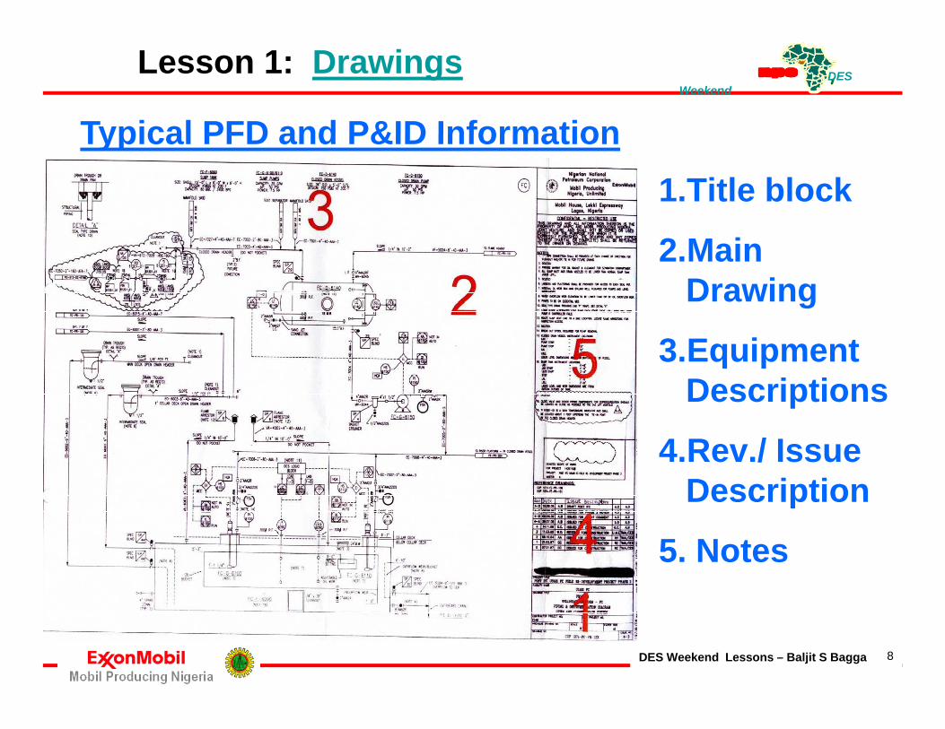
Typical PFD and P&ID Information• 1 - Title block• 2 - Main Drawing• 3 - Equipment Descriptionsq p p• 4 - Revision / Issue Description• 5 - Explanation Notes
DES Weekend Lessons – Baljit S Bagga 7
5 Explanation Notes
DES Weekend
Lesson 1: Drawings
Typical PFD and P&ID Information1.Title block
Typical PFD and P&ID Information
2.Main Drawing
3.Equipment Descriptions
4.Rev./ Issue Descriptionp
5. Notes
DES Weekend Lessons – Baljit S Bagga 8

DES Weekend
Lesson 1: Drawings
PFD and P&ID: Title Block (1)PFD and P&ID: Title Block (1)The title block is usually located at the right bottom
corner of the PFD / P&ID drawing and contains thecorner of the PFD / P&ID drawing and contains the following information:
• Project titlej• Facility name• Drawing Name or TitleDrawing Name or Title• Drawing number• Any other relevant info• Any other relevant info.Info. on who drew it, revised it, approved it, etc. andDates will indicate when all these changes happened
DES Weekend Lessons – Baljit S Bagga 9
Dates will indicate when all these changes happened.

DES Weekend
Lesson 1: Drawings TEST
Wh t d th l tt "P&ID" t d f ?What do the letters "P&ID" stand for?
1, 2, 3, 4 or 5
1. Petrochemical & Industrial Documentation2. Process & Instrumentation Drawing2. Process & Instrumentation Drawing3. Piping & Institutional Diagram4. Piping & Instrumentation Diagram5. P&ID = PEFS (Process Engineering Flow Scheme)
DES Weekend Lessons – Baljit S Bagga 10
( g g )

DES Weekend
Lesson 1: Drawings EXCERCISE
PFD P&ID E i Id tifi tiPFD and P&ID Exercise: Identification
On a PFD or P&IDs, identify:, y
1. The name of the Company2 Th f th Pl t2. The name of the Plant3. The location of the Plant4. The process described in the diagram5. The title of the drawingg6. The current drawing issue number7. The drawing number
DES Weekend Lessons – Baljit S Bagga 11
7. The drawing number

DES Weekend
Lesson 1: DrawingsPFD and P&ID : Main Drawing (2)g ( )Main drawing is the largest section of the drawing, and
contains symbols and lines for:1. Equipment2. Piping connecting pieces of equipment3. Instruments4. Lines connecting instruments5. Instrument control loops6. Line Numbers, Valve Codes etc.PFD does not show every piping connection or other details
found on the P&ID as it a simplified version of P&ID
f f S &DES Weekend Lessons – Baljit S Bagga 12
We will look at each of these types of Symbols & Lines in more details later

DES Weekend
Lesson 1: DrawingsThings to Note on a PFD and P&IDg1. The relative size of the symbols represents the relative
size of the actual equipment.2. The relative position of the symbols also represents
the relative position of actual equipment on the plant.3 O d i h 2 li k3. On a drawing, when 2 lines cross-over or make a
corner without any break in drawn line, it means that those 2 pipes are actually connected in the plant.
4. If the drawn lines cross-over each other but show a break or gap at the cross-over, these pipes are not connected in the plantconnected in the plant
5. A P&ID shows the direction a fluid stream is flowing within a pipe. The direction of flow is drawn as a solid
DES Weekend Lessons – Baljit S Bagga 13
arrowhead on the line representing the pipe

DES Weekend
Lesson 1: Drawings
Things to Note on a PFD and P&IDThings to Note on a PFD and P&ID
• Corners or turns in pipelines on drawing do not necessarily represent bends in real pipelines
• Bends are often put in by designer to make lines fit i th il bl d iin the space available on drawing.
• The lines on the drawing do not represent real distances or real location only relative positiondistances or real location, only relative position
• The drawing may also give descriptions of the pieces of equipment shown in the drawing including theof equipment shown in the drawing, including the information depending on the type of equipment:
DES Weekend Lessons – Baljit S Bagga 14

DES Weekend
Lesson 1: DrawingsPFD / P&ID: Equipment Descriptions (3)PFD / P&ID: Equipment Descriptions (3)The drawing may also give descriptions of the pieces
of equipment shown in the drawing, including the information depending on the type of equipment:
1. Capacity (Volume, Heat Duty etc.)
2. Physical Size (Dimension)
3. Pressure & Temp. informationp4. Horsepower of Pumps/Comp.5. Diff. Head of Pumps etc.5. Diff. Head of Pumps etc.6. Unique equipment number, appearing on each
piece of equipment and on the P&ID equipment symbols
DES Weekend Lessons – Baljit S Bagga 15

DES Weekend
Lesson 1: DrawingsRevision / Issue Descriptions (4)Revision / Issue Descriptions (4)
• The PFD or P&IDs for an area of the plant is revised and re issued every time changes are madeand re-issued every time changes are made.
• The Revision/ issue descriptions, which are usually above the title block tell us exactly what changesabove the title block, tell us exactly what changes were made with each new issue number.
• Revision clouds & Revision triangle with Rev Number• Revision clouds & Revision triangle with Rev. Number are used to identify all changes from previous issue
• With each formal drawing revision previous revisionWith each formal drawing revision, previous revisionclouds are removed but triangles and revision historycan remain.
DES Weekend Lessons – Baljit S Bagga 16

DES Weekend
Lesson 1: Drawings
Revision clouds• Revision clouds and triangles shall be used to identify all
changes from previous formal drawing revision; primary purpose is to improve efficiency of drawing QA/reviews by focusing on changes from previous drawing (see Fig 1).
• With each formal drawing revision, previous revision clouds are removed but triangles and revision history remain.g y
Scope of Work cloudsExisting Drawing
• Scope of work clouds shall be used to identify all scope of work modifications associated with the project (including demolished facilities, fabrication and installation);
• The primary purpose is to highlight to construction contractor, the scope of modifications for the project (Fig 2).
• In addition SoW modification shall be differentiated from
DES Weekend Lessons – Baljit S Bagga 17
existing facilities by using a bolder pen assignment.

DES Weekend
Lesson 1: Drawings
Scope of work clouds Existing Drawing (Cont’d)g g ( )• A control block containing Contractor’s Name, Project “xxx - ##,
Project Title". etc, indicating that the scope of work clouds areapplicable to the project shall be inserted on all modifiedapplicable to the project shall be inserted on all modifieddrawings by Design Contractor (see Fig 3).
"SCOPE OF WORK" BLOCK Existing Drawing
Revision clouds
"SCOPE OF WORK" BLOCK - Existing Drawing
Design Contractor's Name
DENOTES SCOPE OF WORK FOR2
Revision triangle
SOW Cloud
PROJECT: XXX - ##
PROJECT: TitleMASTER: Original's Rev. No
Fig. 1 Fig. 2Fig. 3
DES Weekend Lessons – Baljit S Bagga 18

DES Weekend
Lesson 1: DrawingsScope of work clouds New Drawing
• This is where all information on a new drawing created for a project is associated with the project• This is where all information on a new drawing created for a project is associated with the projectscope (i.e. where no existing facilities are shown on the drawing), then a control block,stating that "All work shown on this drawing is new for project “xxx - ##, project title“ shall beinserted by Design Contractor (Fig 4). No scope of work clouds are required in this case
"SCOPE OF WORK" - New Drawing
Design Contractor's Logo, Name & Address
ALL WORK SHOWN ON THIS DRAWING IS NEW FOR PROJECT XXX - ##
Fig. 4
PROJECT: Title
• *** Where all information on new drawing created for a project includes existing facilities thendrawing shall be treated as an existing drawing i.e. with applicable SOW clouds and bolder penassignment indicating the projects scope of modification (Fig. 2) and control block (Fig. 3)Drawing Interface - Where a base drawing is an IFC drawing from a differentDrawing Interface Where a base drawing is an IFC drawing from a different project, then the SOW cloud from that project shall not be deleted. Instead, a different SOW cloud (as agreed with MPN) shall be used to differentiate the current projects’ scope of modification.
DES Weekend Lessons – Baljit S Bagga 19
A note shall also be included to indicate different projects SOW clouds. Also, the current project scope of modifications shall be of a bolder pen assignment.

DES Weekend
Lesson 1: Drawings
Typical PFD and P&ID Information1.Title block
Typical PFD and P&ID Information
2.Main Drawing
3.Equipment Descriptions
4.Rev./ Issue Descriptionp
5. Notes
DES Weekend Lessons – Baljit S Bagga 20

DES Weekend
Lesson 1: Drawings
PFD and P&ID : Explanation Notes (5)PFD and P&ID : Explanation Notes (5)
• Block 5 on the referenced drawing shows area of the drawing where many different kinds of information may be included.
• While notes may appear in almost any part of the P&ID they are often along the right handthe P&ID, they are often along the right hand side of the drawing.
Congratulations! You have completed Lesson1
Next we look at the PFD’s, P&ID’s and Legends &
DES Weekend Lessons – Baljit S Bagga 21
Next we look at the PFD s, P&ID s and Legends & Symbols for Piping, Valves & Equipment

DES Weekend Lesson 2: Process Flow Diagram
Process Flow DiagramProcess Flow DiagramAs mentioned before, another common type ofanother common type of drawing is the Process Flow Diagram, or PFD,
Th di ti l l f l t th
which is simplified version.
These diagrams are particularly useful to the operators since they carry all the information
d d t f ll d t l it Thneeded to follow a process and control it. They do not show every piping connection or other d t il f d th P&ID
DES Weekend Lessons – Baljit S Bagga 22
details found on the P&ID.

DES Weekend
PFDs, use some of the same
Lesson 2: Process Flow Diagram
symbols as P&IDs, but they do have a few different ones.For example, Heat Exchangers lookFor example, Heat Exchangers look like this & don't include the internals or type of ends. They do, show the tube side and shell side flowstube side and shell side flows.
Towers look similar to the P&IDs, but details are not shown on a PFDshown on a PFD P&IDs will usually give an indication of tray type, and
DES Weekend Lessons – Baljit S Bagga 23
indication of tray type, and nozzle connections for piping
DES Weekend
Lesson 2: Process Flow Diagram
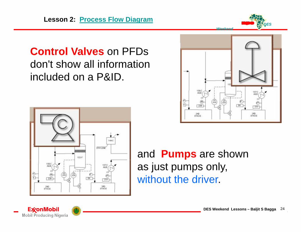
Control Valves on PFDs don't show all information included on a P&ID.
and Pumps are shown as just pumps only, without the driver.
DES Weekend Lessons – Baljit S Bagga 24

DES Weekend
What type of symbols are is shown here?
Lesson 2: Process Flow Diagram
yp y• Heat Exchanger• Control Valve• Pump• Tower
Which is the Pump? 1 2 3 4
Pump symbols on PFDs do not show the pump driverdo not show the pump driver.True or False
DES Weekend Lessons – Baljit S Bagga 25
DES Weekend
PFDs include info on Flow rates
Lesson 2: Process Flow Diagram
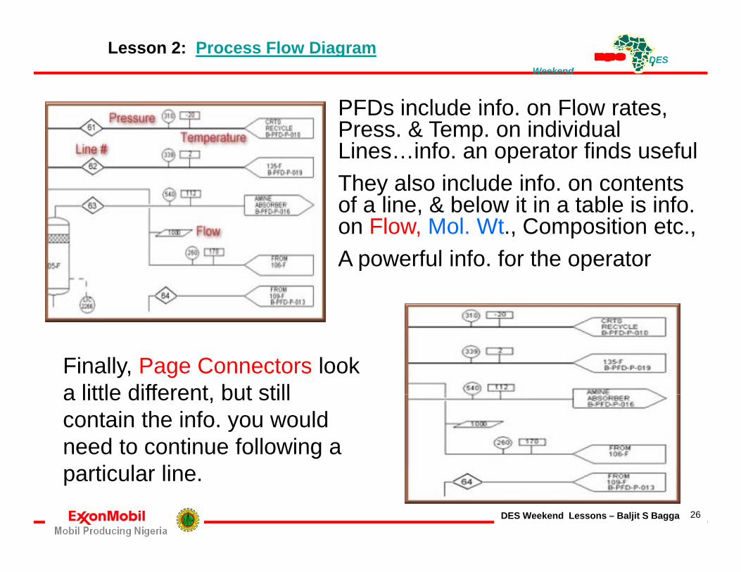
PFDs include info. on Flow rates, Press. & Temp. on individual Lines…info. an operator finds usefulTh l i l d i f t tThey also include info. on contents of a line, & below it in a table is info. on Flow, Mol. Wt., Composition etc., A f l i f f hA powerful info. for the operator
Finally, Page Connectors look a little different but stilla little different, but still contain the info. you would need to continue following a
ti l li
DES Weekend Lessons – Baljit S Bagga 26
particular line.

DES Weekend
Where can you find information on the
Lesson 2: Process Flow Diagram
yComposition of product in a line?• In the lab report guidebook• In a table on the PFD• In the process description
In the product spec sheets• In the product spec sheets
PFDs include info. on Flow rates, Press & Temp on individualPress. & Temp. on individual Lines…info. an operator finds usefulThey also include info. on contents yof a line, & below it in a table is info. on Flow, Mol. Wt., Composition etc., A powerful info for the operator
DES Weekend Lessons – Baljit S Bagga 27
A powerful info. for the operator

DES Weekend
Where do you find who revised a drawing?
Lesson 2: Process Flow Diagram
e e do you d o e sed a d a g• In the drawing title block• In the master files• In the drafting room log book• In the area of the drawing that was revisedAll drawings have a title block containing drawing name, its number, info. on who d i i d i d i d ddrew it, revised it, approved it, and date etc.
In SummaryBoth P&IDs and PFDs contain valuable info.Both P&IDs and PFDs contain valuable info. All you need to make use of this info. is a little knowledge and some practice. These diagrams are available 24 hours a day, g y365 days a year. You should always know where they are and use them to help you make the right decisions.
DES Weekend Lessons – Baljit S Bagga 28
Congratulations! You have completed Lesson 2
DES Weekend Lesson 3: Piping & Instrumentation Diagram
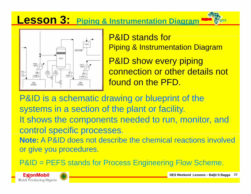
P&ID stands forP&ID stands for Piping & Instrumentation Diagram
P&ID show every pipingP&ID show every piping connection or other details not found on the PFD.
P&ID is a schematic drawing or blueprint of the systems in a section of the plant or facility
found on the PFD.
systems in a section of the plant or facility. It shows the components needed to run, monitor, and control specific processes.p pNote: A P&ID does not describe the chemical reactions involved or give you procedures.
DES Weekend Lessons – Baljit S Bagga 29
P&ID = PEFS stands for Process Engineering Flow Scheme.

DES Weekend
Lesson 3: Piping & Instrumentation Diagram
Components of a P&ID includes:p1. Plant Equipment;2. Piping Lines that connects the Equipment;p g q p ;3. Instrument Lines (or Tubing) and instruments
used to monitor and control the process.Importance of the P&ID
P&IDs are important tools for:& p1. Working safely2. Maintaining a process operationa a g a p ocess ope a o3. Understanding & Communicating about a process4. Training
DES Weekend Lessons – Baljit S Bagga 30
a gNote: P&IDs must be kept accurate & up-to-date

DES Weekend
Let's focus on P&IDs, drawn
Lesson 3: Piping & Instrumentation Diagram
Let s focus on P&IDs, drawn to show exact equipment in plant in complete detail, termed “Environmental detail“ This is because drawings show
l i hevery location where an Environmental release is possible
This means showing everyThis means showing every vessel, pump, exchanger, pipe, drain, and trap. It even includes every pipeIt even includes every pipe union and every pipe flange. In other words, they are accurate representations of
DES Weekend Lessons – Baljit S Bagga 31
accurate representations of everything within the plant.

DES Weekend
A i i
Lesson 3: Piping & Instrumentation Diagram
As you can imagine, many drawings are needed to represent an entire plant.p pSo, a method for showing where a pipe goes next appears on every drawingappears on every drawing.
Remember, these are drawings and do not show physical locations of equipment within the plant. In this sense they are SchematicsIn this sense, they are Schematics that show Functional relationships and connections of the equipment.
DES Weekend Lessons – Baljit S Bagga 32
DES Weekend
TESTING
Lesson 3: Piping & Instrumentation Diagram
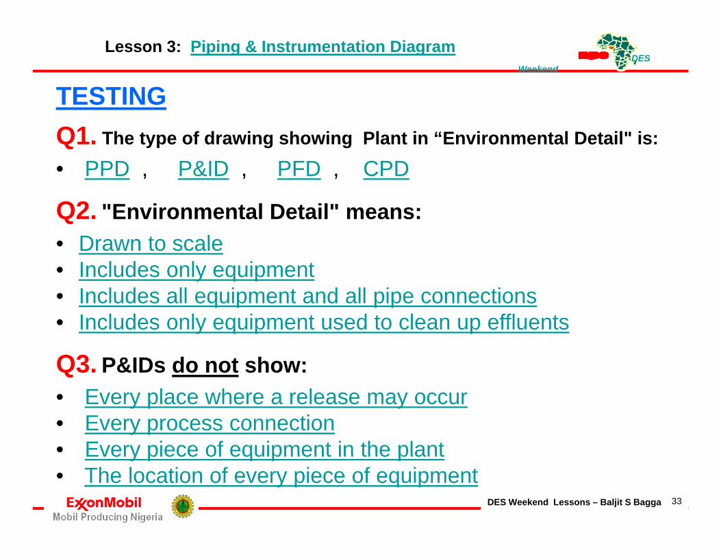
TESTINGQ1. The type of drawing showing Plant in “Environmental Detail" is:
• PPD P&ID PFD CPDPPD , P&ID , PFD , CPD
Q2. "Environmental Detail" means:• Drawn to scale• Drawn to scale• Includes only equipment• Includes all equipment and all pipe connections
I l d l i d l ffl• Includes only equipment used to clean up effluents
Q3. P&IDs do not show:• Every place where a release may occur• Every process connection• Every piece of equipment in the plant
DES Weekend Lessons – Baljit S Bagga 33
Every piece of equipment in the plant• The location of every piece of equipment

DES Weekend
1 Type of drawing showing plant in "environmental detail"
Lesson 3: Piping & Instrumentation Diagram - ANSWERS
1. Type of drawing showing plant in environmental detailP&IDs are drawn to show you the exact equipment in the plant in complete detail. This is termed "environmental detail." This is because the drawings show every location where an environmental release is possible.
2. "Environmental Detail" means: P&ID Includes all equipment & all pipe connections, showing every vessel, pump, exchanger pipe drain and trap It even includes every pipeexchanger, pipe, drain, and trap. It even includes every pipe union and every pipe flange. In other words, they are accurate representations of everything within the plant.
3. P&IDs do not show: Location of every piece of equipmentRemember, these are drawings and, as such, do not show you
DES Weekend Lessons – Baljit S Bagga 34
the physical locations of the equipment within the plant.
DES Weekend
B l i t d P&I Di
Lesson 3: Piping & Instrumentation Diagram
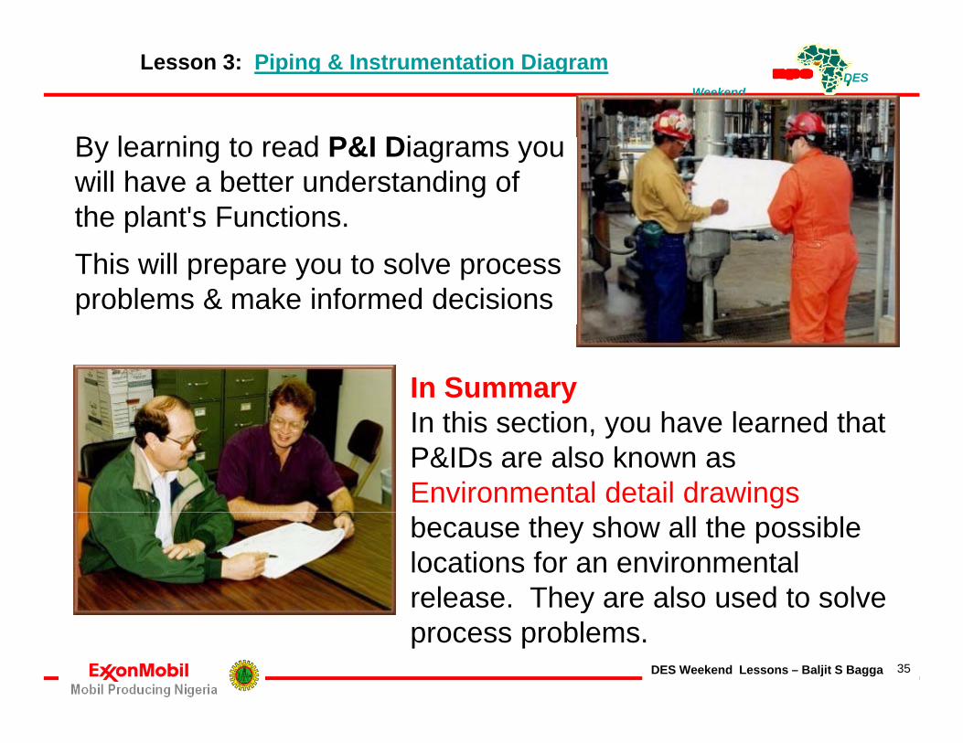
By learning to read P&I Diagrams you will have a better understanding of the plant's Functions. pThis will prepare you to solve process problems & make informed decisions
In SummaryIn this section you have learned thatIn this section, you have learned that P&IDs are also known as Environmental detail drawingsbecause they show all the possible locations for an environmental release. They are also used to solve
DES Weekend Lessons – Baljit S Bagga 35
release. They are also used to solve process problems.
DES Weekend
Which is not a main purpose for P&IDs?
Lesson 3: Piping & Instrumentation Diagram
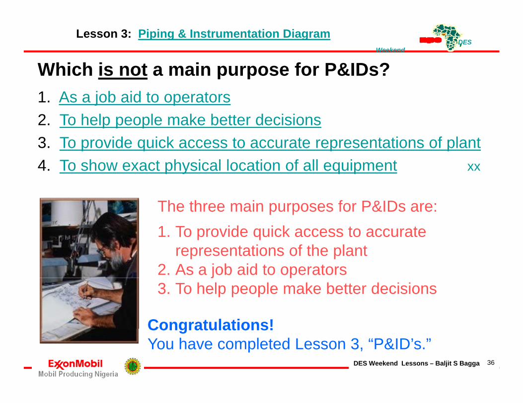
Which is not a main purpose for P&IDs?1. As a job aid to operators2. To help people make better decisionsp p p3. To provide quick access to accurate representations of plant4. To show exact physical location of all equipment xx
The three main purposes for P&IDs are: 1 T id i k t t1. To provide quick access to accurate
representations of the plant 2. As a job aid to operators j p3. To help people make better decisions
Congratulations!
DES Weekend Lessons – Baljit S Bagga 36
Congratulations!You have completed Lesson 3, “P&ID’s.”

DES Weekend
Lesson 4: Piping
PipingPiping carries its ownPiping carries its own set of symbols.
Main Process Lines are shown as Thicker lines than ili li A k th l t i i iauxiliary lines. As you know, the plant piping is a
series of connected pieces of pipe, andPi ti l h P&ID
DES Weekend Lessons – Baljit S Bagga 37
Pipe connections are also shown on a P&ID.

DES Weekend
A long line of letters and numbers d i t h li i th l t
Lesson 4: Piping LINE NUMBERING -
designates each line in the plant, e.g. First letter is P (Process Service)
1 Line Service or what it carries1. Line Service, or what it carries.
2. Second group is the Unit & Line No
3. Next is the Pipe Size.
4. Pipe schedule or Wall Thickness
5. Pipe Material Classification
6 insulation designation if required6. insulation, designation if required.
A complete list of the designations is i i th P&ID l d h t
DES Weekend Lessons – Baljit S Bagga 38
given in the P&ID legend sheets.

DES Weekend
Drawing page Arrows are found on
Lesson 4: Piping
Drawing page Arrows are found on piping to indicate which drawing to refer to for the continuation of a line. Th A h hThese Arrows are shown here. Notice that there are different types depending on how many lines of information need to be included.
Instrument Lines are drawn as shown here. There are special symbols for Pneumatic Transmissionand Electrical transmission
DES Weekend Lessons – Baljit S Bagga 39
and Electrical transmission.

DES Weekend
Other abbreviations are also shown,
Lesson 4: Piping
e.g., the P&ID will show things like • CSC (Car Seal Closed), • CSO (Car Seal Open)• CSO (Car Seal Open), • FC (Fail Closed) & FO (Fail Open) Once again, the legend contains all g , gthe abbreviations.
In SummaryyIn this section, you have learned How each Line is identified &
h t S b l d twhat Symbols are used to represent Instrument Linesand Pneumatic and Electrical
DES Weekend Lessons – Baljit S Bagga 40
and Pneumatic and Electricaltransmissions.

DES Weekend
What does "CSC" stand for on a P&ID?
Lesson 4: Piping
What does CSC stand for on a P&ID?• Correct Seal Connected• Cannot See Clearly• Car Seal Closed• Car Seal Closed• Customer Service Center
Which of the following information isWhich of the following information is included in the line designation?• Line service• Unit and line numberUnit and line number• Insulation• Pipe size• All of the above
Which is the electrical line symbol?• Answer One
DES Weekend Lessons – Baljit S Bagga 41
Answer One• Answer Two1 2

DES Weekend
Typical Branch Connection Details
DES Weekend Lessons – Baljit S Bagga 42

DES Weekend
Lesson 4: Piping
Which is the Instrument line symbol?yAnswer One or Answer Two
Instrument lines are drawn as shown There are special symbols for Pneumatic transmission and Electrical transmission.Electrical transmission.
1 2
DES Weekend Lessons – Baljit S Bagga 43
Congratulations! You have completed Lesson 4 Piping

DES Weekend
V l
Lesson 5: ValvesValvesLet's continue with P&IDs b i i h hby examining how they are arranged and defining the most important symbolsmost important symbols.
P&ID d diP&IDs are drawn according to some conventions, e.g.Flows are usually shown as going from left to right, at least as much as possible
DES Weekend Lessons – Baljit S Bagga 44
least as much as possible.
DES Weekend
V l k i t
Lesson 5: Valves
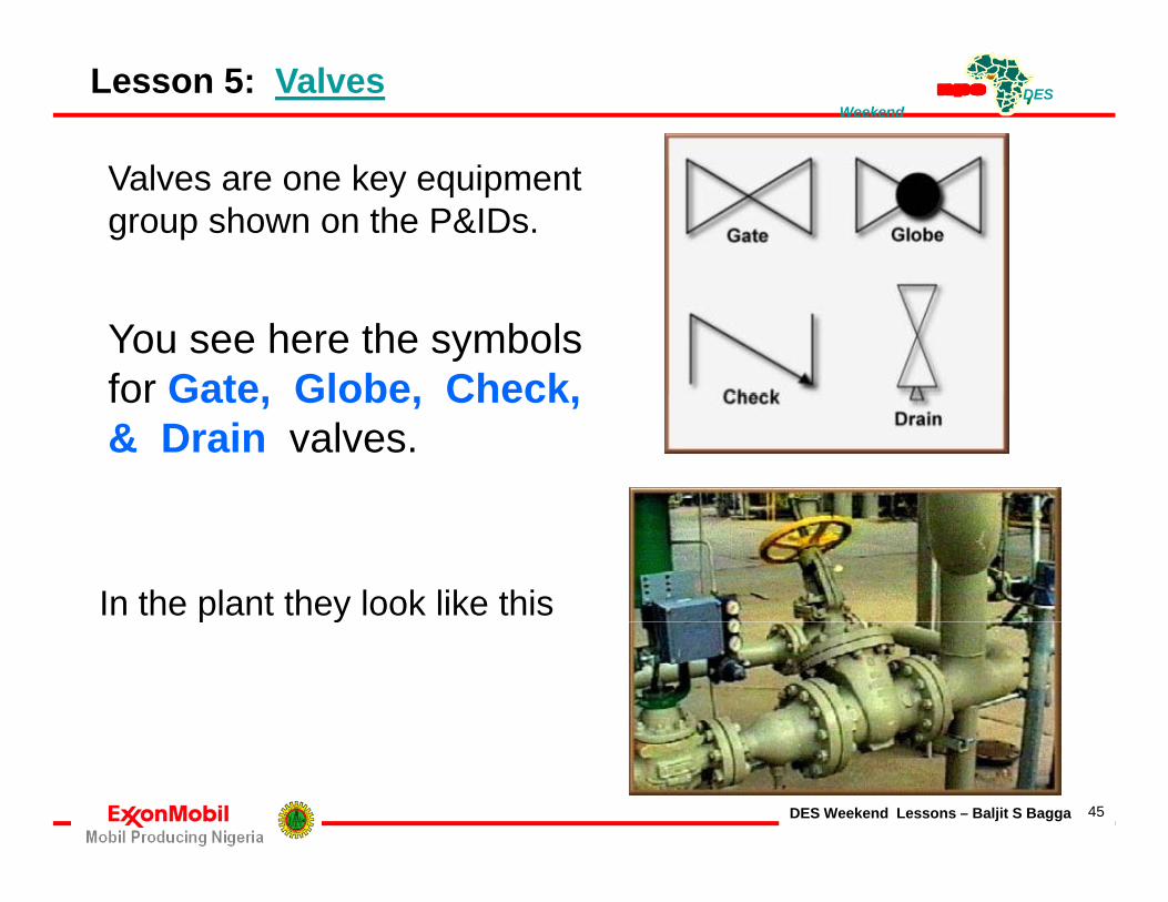
Valves are one key equipment group shown on the P&IDs.
You see here the symbols for Gate Globe Checkfor Gate, Globe, Check, & Drain valves.
In the plant they look like thisp y
DES Weekend Lessons – Baljit S Bagga 45

DES Weekend
On P&IDs flows are
Lesson 5: Valves
On P&IDs, flows are typically shown as:Flowing from right to leftDashed linesFlowing from left to rightRed lines
Which is the Gate valve?Which is Check valve?Which is Globe valve?
1 2 3 4
DES Weekend Lessons – Baljit S Bagga 46

DES Weekend
5 A h i i l l i h
Lesson 5: Valves
5. Another critical valve is the Pressure Relief Valve (PRV).
This valve is used to Release Pressure from the process lines before it reaches a critical level.
DES Weekend Lessons – Baljit S Bagga 47

DES Weekend
6. Finally, there are several types of
Lesson 5: Valves
Control Valves in the plant. The symbols all start with this
"bow-tie with a hat" symbol represents a Diaphragm Actuatedcontrol valvecontrol valve.
More details may be added to this Symbol to further define its function
e.g. this is a Self-contained Back Pressure Regulator
DES Weekend Lessons – Baljit S Bagga 48
Back Pressure Regulator.

DES Weekend
Q i Wh i hi ?
Lesson 5: Valves
Question - What is this? a self-contained back pressure regulator.
This is a diaphragm actuateddiaphragm actuatedcontrol valve with aPositioner.
DES Weekend Lessons – Baljit S Bagga 49

DES Weekend
BSB
Figure 6: P&ID Valve IdentificationValve Identification
Valve Size, Company Valve Label• System No,• Equipment• Identification No.,• Sequential No.
Valve Procurement Specification Code:1. Pressure Class2. Valve Type3. Valve Speciality4. Body Material5. End Connection
DES Weekend Lessons – Baljit S Bagga 50
6. Suffixes

DES Weekend
Which is basic control valve? 1, 2 or 3
Lesson 5: Valves TESTING
3 is a symbol, start with "bow-tie with a hat" representing a diaphragm actuated control valveMore details added to symbol to further ydefine its function
Which is self-contained back pressure pvalve? 2 is a self-contained back-press. Regulator
Which is control valve with Positioner?1 is a Diaphragm actuated Control Valve
DES Weekend Lessons – Baljit S Bagga 51
with a Positioner.
DES Weekend
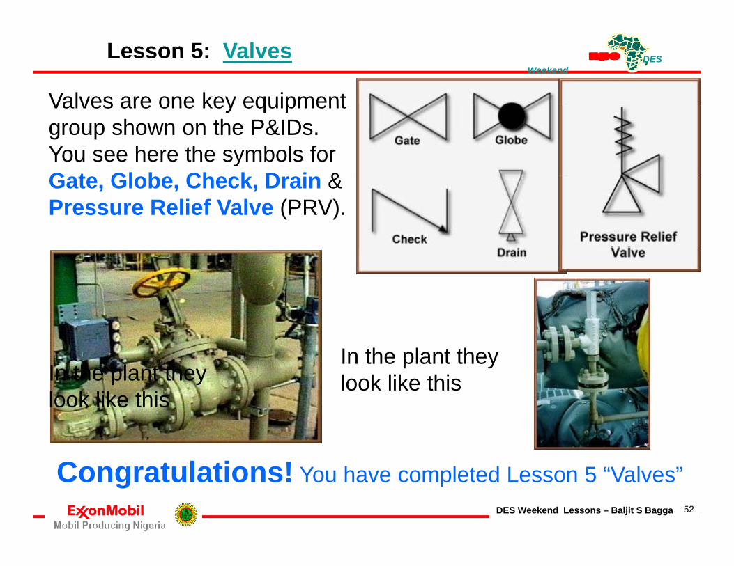
Valves are one key equipment
Lesson 5: Valves
Valves are one key equipment group shown on the P&IDs. You see here the symbols for G t Gl b Ch k D i &Gate, Globe, Check, Drain & Pressure Relief Valve (PRV).
In the plant they In the plant they look like this
C t l ti !
look like thislook like this
DES Weekend Lessons – Baljit S Bagga 52
Congratulations! You have completed Lesson 5 “Valves”

DES Weekend
Equipment
Lesson 6: EQUIPMENTEquipmentThere are symbols for all pieces of equipment in thepieces of equipment in the plant, such as process Vessels and HeatersVessels and Heaters.Centrifugal Pumps with Elect Motor driversElect. Motor drivers,Centrifugal Pumps withTurbine drivers andTurbine drivers, and Reciprocating Pumps are also examples of plant equipment
DES Weekend Lessons – Baljit S Bagga 53
also examples of plant equipment
DES Weekend
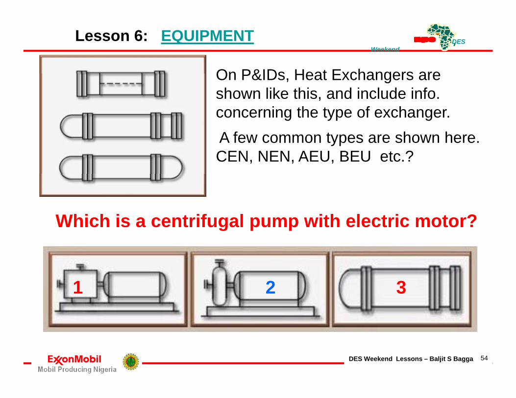
On P&IDs Heat Exchangers are
Lesson 6: EQUIPMENT
On P&IDs, Heat Exchangers are shown like this, and include info. concerning the type of exchanger.A few common types are shown here. CEN, NEN, AEU, BEU etc.?
Which is a centrifugal pump with electric motor?Which is a centrifugal pump with electric motor?
1 2 3
DES Weekend Lessons – Baljit S Bagga 54

DES Weekend
Which is a centrifugal pump
Lesson 6: EQUIPMENT
Which is a centrifugal pump with electric motor?
C t if l ith tCentrifugal pumps with motor drivers, centrifugal pumps with turbine drivers, and reciprocating pumps are also examples of plant equipment.
Which is a reciprocating pump with electric motor driver?
DES Weekend Lessons – Baljit S Bagga 55

DES Weekend
Which is a heat exchanger?
Lesson 6: EQUIPMENT
1 2 3
g
1 2 3
On P&IDs heat e changers areOn P&IDs, heat exchangers are shown like this, and include information concerning the type of exchanger. A few common types are shown here.
DES Weekend Lessons – Baljit S Bagga 56

DES Weekend
Finally Control Symbols are also
Lesson 6: EQUIPMENT
Finally, Control Symbols are also included. The symbols for the basic types of instruments - Field mounted,Control Room instrument Panel, Local Panel mounted, and DCS System Points - are shown here
Along with the instrument, a Tag is included on the P&ID which shows theP&ID which shows the instrument Type, its Function, and Location.
DES Weekend Lessons – Baljit S Bagga 57
Function, and Location.
DES Weekend
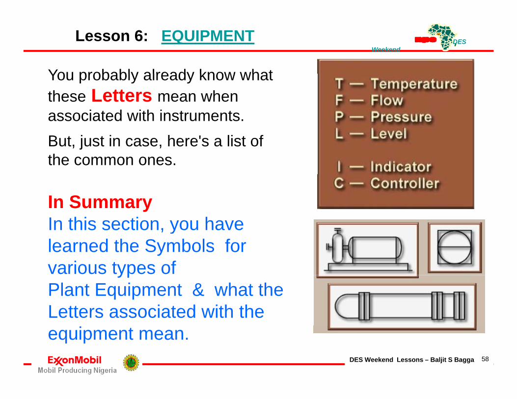
You probably already know what
Lesson 6: EQUIPMENT
You probably already know what these Letters mean when associated with instruments. But, just in case, here's a list of the common ones.
In SummaryIn this section you haveIn this section, you have learned the Symbols for various types of ypPlant Equipment & what the Letters associated with the
DES Weekend Lessons – Baljit S Bagga 58
equipment mean.

DES Weekend
Which is a DCS controller?
Lesson 6: EQUIPMENT
Which is a DCS controller?
1 2 3 4
What type of symbol is shown in
3
No. 4 above ?• DCS system point• Field instrument• Local panel instrument
DES Weekend Lessons – Baljit S Bagga 59
• Control room instrument panel

DES Weekend
Congratulations!You have completed Lesson 6, “Equipment and also completed the course:
Th A t f R di P&ID & PFDThe Art of Reading P&IDs & PFDs
THANK YOU !!
DES Weekend Lessons – Baljit S Bagga 60