Embed Size (px)
Citation preview
AERODYNAMICSAlmost irreconcilable: minimum sink with good thermalling qualities, excel-lent glide also at higher speeds, as well as very docile handling. These goals could be fulfilled in the Antares. The aerodynamic design is the result of a multi-year research project, and it was created, uncompromising-ly, as a unified design. In doing so, all conceivable measures of optimization were utilized.
WING GEOMETRYAn extremely slender super-ellipse defines the wing geometry of the Antares 20E. Through this geometry, the induced drag is reduced to the theoretical mini-mum. This corresponds with the optimal values of the untwisted elliptical wing, but without having to accept the critical stall characteristics of this classic layout. The wide outer wings and winglets effectuate very docile flight qualities. In addition, the winglets facilitate 5 percent reduction of the induced drag. As a result, the induced drag of the 20m Antares wing is only 95 percent of the induced drag of an equivalent flat, untwisted elliptical wing.
AIRFOILSNine perfectly harmonized airfoils ensure a minimal profile drag. The laminar flow on the bottom surface reaches 95 percent of the airfoil chord. Here, a zig-zag shaped turbulator tape forces a transition from a la-minar to a turbulent boundary layer. A turbulator tape that is properly dimensioned and positioned according to the boundary layer conditions has no significant performance drawbacks when compared to boundary layer blowing. However, the tape is significantly less sensitive to dirt and scratches. The airflow over the top surface remains laminar up to 75 percent of the airfoil chord. This is currently the highest achievable value for an airfoil without boundary layer suction.
DETAIL PERFECTIONAn additional negative flap setting of -3° can be selected for fast glide. This allows for very high speed flights with hitherto unachievable glide performances. Only at air-speeds of 220 kph / 119 kts to 245 kph / 132 kts (depending on the wing loading), do the airfoils leave the laminar drag bucket. The compact electric motor permits an optimal rear fuselage contraction, which results in a further drag reduction. Aerodynamic performance losses in the area of the wing-fuselage junction have been minimized through a special fuselage center section design combined with the use of custom turbulent airfoils in the vicinity of the fuselage. The weight of the Antares is actually equal to or less than that of a conventionally powered self launching sailplane with similar wing area and wingspan.
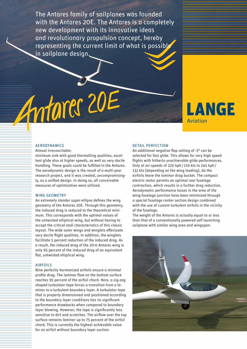
The Antares family of sailplanes was founded with the Antares 20E. The Antares is a completely new development with its innovative ideas and revolutionary propulsion concept, hereby representing the current limit of what is possible in sailplane design.
HANDLINGFull span flaperons give the Antares 20E extreme agility. The flaperons are actuated through a novel control mechanism which, together with a consequent use of high quality ball bearings, rather than glide bearings, results in substantially reduced friction resistance for all controls. This, in combination with the outstanding flaperon differentiation, enables the very smooth flight controls of the Antares.Large tail surfaces with high aspect ratios and state of the art airfoils ensure perfect maneuverability in all flight and loading conditions while keeping empenna-ge drag at a minimum. High extending, triple cascading Schempp-Hirth spoi-lers allow for steep and safe approaches with limited loss of lift. This has the effect that the stall speed hardly increases with the extension of the spoilers. All these aspects make the Antares an extremely agile, but not “skittish” aircraft. The Antares 20E is stable in flight, but reacts communicatively to thermal activi-ties, and offers an agility comparable to that of 15m sailplanes. For example, a +/-45°-curve reversal at 115 kph / 62 kts takes only 3.2 seconds.
PROPULSIONThe foundation for the Antares concept was laid with the patented electrical propulsion system of the Antares 20E. The system merges light, powerful and environmentally friendly batteries with a 42 kW brushless outrunner electric motor, novel power electronics and a large, very slowly revolving propel-ler. All components were developed and optimized to one another in order to create a complete system that was more than the sum of its parts. For the first time, a complete propulsion architecture was developed for one particular sailplane.
BATTERY SYSTEMThe Antares 20E comes equipped with 72 Lithium-Ion cells of the type SAFT VL41M. These are arranged in modules of 3, and located in the inner wing. Each individual cell is carefully and redundantly monitored in order to ensure that they can deliver maximum performance while simultaneously being operated within safe parameters. A full battery charge requires approximately 10h, and enables the Antares 20E to achieve a total climb altitude (including takeoff) of approximately 3.500 m / 11.500 ft.
MOTORThe electric motor EM42, with which the Antares 20E is equipped, is the only electric motor to this date, which is EASA certified as an aircraft motor. It is a DC brushless outrunner, which operates at voltages bet-ween 190V and 297V and currents up to 160A.In electric motors, high power is usually acheived by making the motor run at high RPMs. This is not what is desired for an aircraft motor that is to drive an efficient propeller. The EM42 generates a maximum of 42 kW of power while running at low speeds. In doing so, it generates a maximum torque of 216 Nm. The total efficiency of motor and controller is 90 percent.
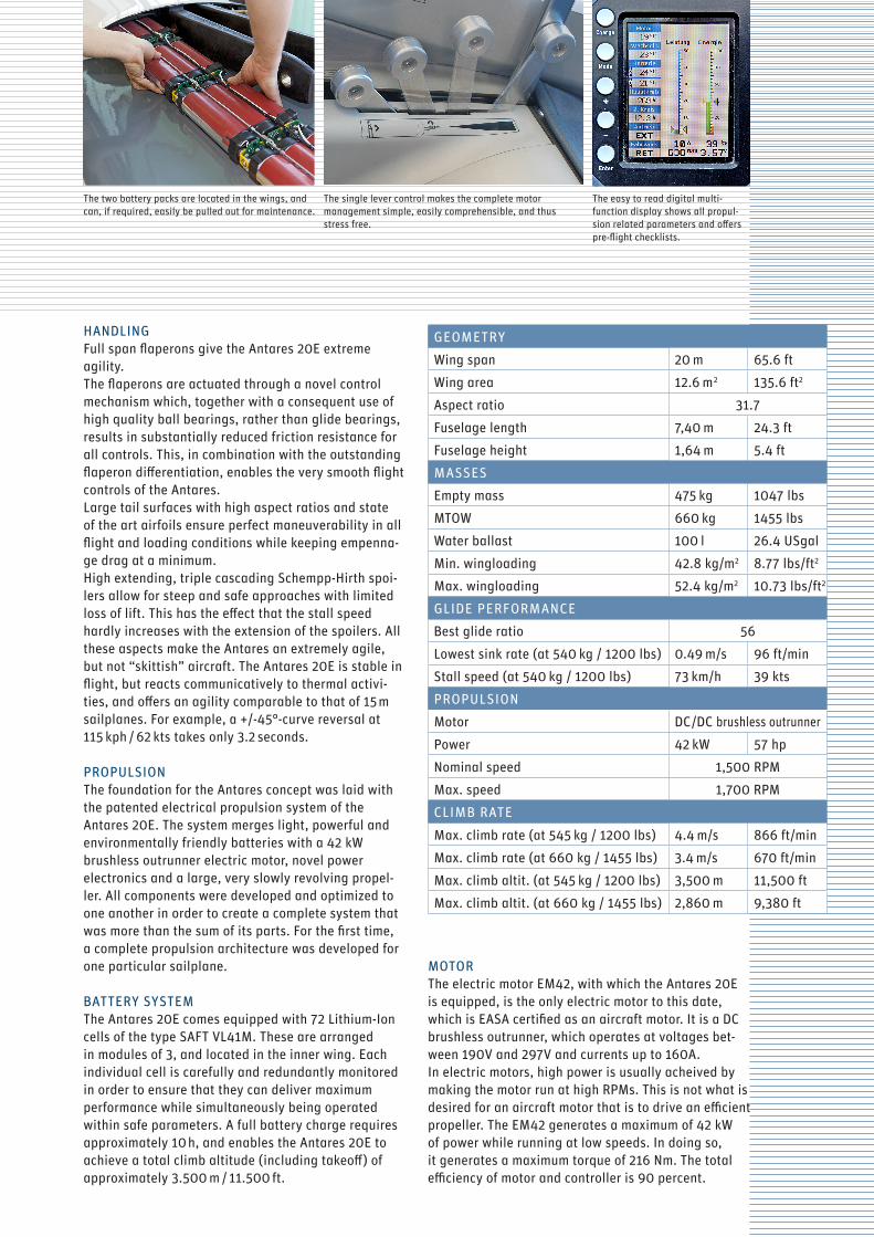
The two battery packs are located in the wings, and can, if required, easily be pulled out for maintenance.
The single lever control makes the complete motor management simple, easily comprehensible, and thus stress free.
The easy to read digital multi- function display shows all propul-sion related parameters and offers pre-flight checklists.
GEOMETRY
Wing span 20 m 65.6 ft
Wing area 12.6 m2 135.6 ft2
Aspect ratio 31.7
Fuselage length 7,40 m 24.3 ft
Fuselage height 1,64 m 5.4 ft
MASSES
Empty mass 475 kg 1047 lbs
MTOW 660 kg 1455 lbs
Water ballast 100 l 26.4 USgal
Min. wingloading 42.8 kg/m2 8.77 lbs/ft2
Max. wingloading 52.4 kg/m2 10.73 lbs/ft2
GLIDE PERFORMANCE
Best glide ratio 56
Lowest sink rate (at 540 kg / 1200 lbs) 0.49 m/s 96 ft/min
Stall speed (at 540 kg / 1200 lbs) 73 km/h 39 kts
PROPULSION
Motor DC/DC brushless outrunner
Power 42 kW 57 hp
Nominal speed 1,500 RPM
Max. speed 1,700 RPM
CLIMB RATE
Max. climb rate (at 545 kg / 1200 lbs) 4.4 m/s 866 ft/min
Max. climb rate (at 660 kg / 1455 lbs) 3.4 m/s 670 ft/min
Max. climb altit. (at 545 kg / 1200 lbs) 3,500 m 11,500 ft
Max. climb altit. (at 660 kg / 1455 lbs) 2,860 m 9,380 ft
PROPELLERDeveloped and optimized especially for the Antares 20E, the propeller blades are mounted directly onto the outrunner electric motor.A propeller diameter of 2 m / 6.6 ft leads to low RPM, high efficiency and low noise emissions. The available motor power is independent from density altitude, therefore the propeller is the only altitude dependent propulsive component. An increase in altitude of 3.000 m / 9.800 ft results in an efficiency loss of only 4 percent.
PROPULSIVE CONTROLS All propulsive functions, such as pylon extension and retraction, propeller braking and aligning, as well as power control are performed by a single power lever in the left side panel. The propulsive control is intuitive, and can be performed blind, which means that pilot di-version and the risk of operating errors are reduced to a minimum. Levers for flaps, spoilers and trim are also located in the left side panel. Landing gear retraction is electro-hydraulically actuated, and it is controlled by a switch in the instrument console. Consequently, the pilot can keep his right hand on the stick at all times, and does not need to change hands. This makes it easier to focus on flying, and on the surrounding airspace.
COCKPIT Designed according to current guidelines for work-place ergonomy, the cockpit of the Antares can be perfectly adjusted to almost every pilot. The seat-pan can be moved diagonally between „for-ward and up“ and „rearward and down“. This means that pilots of all sizes have approximately the same view out of the cockpit, and that stick and instrument panel will always be located in the optimal position.
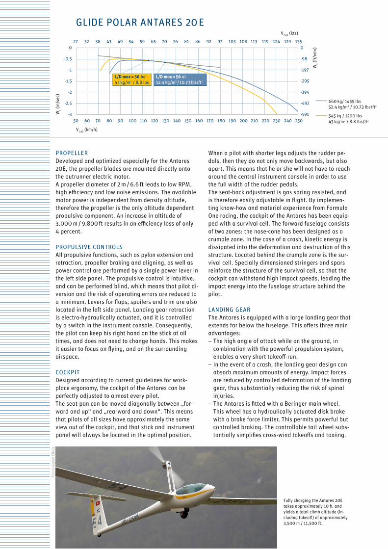
GLIDE POLAR ANTARES 20 E
L/D max = 56 at 52.4 kg/m2 / 10.73 lbs/ft2
L/D max = 56 bei 43 kg/m2 / 8.8 lbs
0
-98
-197
-295
-394
-492
-591Ws (
m/s
ec)
Ws (
ft/m
in)
V CAS (km/h)
V CAS (kts)
660 kg/ 1455 lbs 52.4 kg/m2 / 10.73 lbs/ft2
545 kg / 1200 lbs 43 kg/m2 / 8.8 lbs/ft2
Fully charging the Antares 20E takes approximately 10 h, and yields a total climb altitude (in-cluding takeoff) of approximately 3,500 m / 11,500 ft.
Fot
o G
régo
ry C
livaz
When a pilot with shorter legs adjusts the rudder pe-dals, then they do not only move backwards, but also apart. This means that he or she will not have to reach around the central instrument console in order to use the full width of the rudder pedals.The seat-back adjustment is gas spring assisted, and is therefore easily adjustable in flight. By implemen-ting know-how and material experience from Formula One racing, the cockpit of the Antares has been equip-ped with a survival cell. The forward fuselage consists of two zones: the nose-cone has been designed as a crumple zone. In the case of a crash, kinetic energy is dissipated into the deformation and destruction of this structure. Located behind the crumple zone is the sur-vival cell. Specially dimensioned stringers and spars reinforce the structure of the survival cell, so that the cockpit can withstand high impact speeds, leading the impact energy into the fuselage structure behind the pilot.
LANDING GEARThe Antares is equipped with a large landing gear that extends far below the fuselage. This offers three main advantages:– The high angle of attack while on the ground, in
combination with the powerful propulsion system, enables a very short takeoff-run.
– In the event of a crash, the landing gear design can absorb maximum amounts of energy. Impact forces are reduced by controlled deformation of the landing gear, thus substantially reducing the risk of spinal injuries.
– The Antares is fitted with a Beringer main wheel. This wheel has a hydraulically actuated disk brake with a brake force limiter. This permits powerful but controlled braking. The controllable tail wheel subs-tantially simplifies cross-wind takeoffs and taxiing.
50 60 70 80 90 100 110 120 130 140 150 160 170 180 190 200 210 220 230 240 250
0
-0,5
-1
-1,5
-2
-2,5
-3
27 32 38 43 49 54 59 65 70 76 81 86 92 97 103 108 113 119 124 129 135

Lange Aviation GmbH Brüsseler Strasse 30 66482 Zweibrücken, GermanyFon +49.6332.96 27-0 Fax +49.6332.96 27-19 [email protected] www.lange-aviation.com
ERGONOMIC SEATINGDesigned according to current guidelines for work-place ergonomy, the cockpit of the Antares can be perfectly adjusted to almost every pilot. The seat-pan can be moved diagonally between „forward and up“ and „rearward and down“. The seat-back is in-flight adjustable. This means that pilots of all sizes have approximately the same view out of the cockpit, and that stick and instrument panel will always be located in the optimal position.
EASE OF USELevers for flaps, spoilers and trim, as well as the propulsion control are all located in the left side panel. Consequently, the pilot can keep his right hand on the stick at all times.The retraction and extension of the landing gear is electro-hydraulically actuated, and it is controlled by a switch in the instrument console. This avoids control errors due to mistaken levers.
RUDDER PEDAL ADJUSTMENTThe rudder pedals move apart when adjusted backwards, so that pilots with shorter legs do not have to reach around the central instrument console in order to use the full width of the rudder pedals.
AUDIO SYSTEMAn audio system that is novel to this class of aircraft assists during flight and forwards system warnings. The pilot can trust that the calm voice of this „embedded co-pilot“ will point out possible problems or malfunctions. There is no need to continuously monitor the propulsive instruments, and the pilot can fully focus on flying. The quiet and vibration-free motor integration allows comfortable communications, also during takeoff.
ANTARES 20E20 m wingspanElectric propulsion
With a 20 m wingspan, the Antares flies „just for fun“ with the high performance of a modern open class sailplane.Optimal glide and thermaling performances combine with easy handling on the ground: This is the nicest way to fly!
ERGONOMICS – COMFORT IS SAFETY
IMPR
INT
Phot
os: M
atth
ias
Fisc
her:
Titl
e pa
ge b
elow
; Fra
nk H
erzo
g, w
ww
.aer
o-ar
t.de
: inn
er p
age,
bac
k pa
ge; W
orks
hop
phot
ogra
phy:
Titl
e ab
ove,
inne
r pag
e ce
nter
Co
ncep
t and
Lay
out:
M8
Med
ien,
Ber
lin; m
ail@
mac
ht.d
e. A
ll te
chni
cal d
ata
may
cha
nge
with
out p
rior
not
ice.
03.
2017