Embed Size (px)
Citation preview

International Conference KNOWLEDGE-BASED ORGANIZATION Vol. XXI No 3 2015
THE ANALYSIS OF THE VIBRATORY MOVEMENT OF THE GUN BARREL AND ITS INFLUENCE ON THE FIRING ACCURACY
Alin-Constantin SAVA, Ioan-Liviu PITICARI, Diana-Georgeta NISTORAN, Cristian-Emil MOLDOVEANU
Military Technical Academy, Bucharest, Romania, [email protected]
Abstract: It is known that the forces and shocks that occur during the firing process of a firearm induce vibrations to the barrel of the weapon and to the weapon as a whole. There are flexural, longitudinal, radial and torsional vibrations. The most important ones are considered to be the flexural or bending vibrations, especially the ones recorded in the muzzle section. This paper presents a method of recording the flexural vibrations of the barrel in the muzzle section of a 5,56mm automatic rifle and the influence of muzzle devices, using modern equipment (high speed cameras) and dedicated software.
Keywords: vibratory movement, firing accuracy, bending vibrations, high speed camera
1. IntroductionPrevious investigations of the jump have shown that vibrations of the barrel of a weapon during the firing process, transmitted into the entire body of the firearm, along with the dynamic couple generated by the recoil forces, cause the jump error [1]. The jump error is understood to be the angle between a reference line drawn through the weapon barrel prior to firing the round and the actual initial flight direction (launch direction) of the projectile. The ballistic jump error is normally used, meaning the angle measured between the tangent to the axis of the bore at the bullet exit time (the point in time when the driving band of the projectile leaves the muzzle) and the same line before shooting [1]. The oscillations of the barrel, along with other initial perturbing factors of the
projectile (nutation of projectile at muzzle and the influence of propellant gases that flow out after firing) influence the kinematics of the bullet when it leaves the muzzle. The most important factor of all is barrel oscillations, particularly the bending vibrations [1, 2]. The oscillation phase when the projectile exits the barrel is passed on to the projectile, causing the bullet to leave the barrel at a specific angle up against the original axis of the muzzle (ballistic jump), also with a vertical velocity and a vertical acceleration, therefore influencing the trajectory and the hitting point at the target. Bending vibrations are mainly caused by the pressure of hot gases produced from the burning propellant, but also by the forces occurring between the projectile and the
DOI: 10.1515/kbo-2015-0150 © 2015. This work is licensed under the Creative Commons Attribution-NonCommercial-NoDerivatives 3.0 License.
883 UnauthenticatedDownload Date | 2/15/17 8:37 PM

barrel (consequence of the clearance between the driving band of the projectile and the barrel grooves), by static disequilibrium (the projectile centre of mass is outside the axis of symmetry) and dynamic disequilibrium (some mobile parts of the weapon have the centre of mass outside the axis of symmetry). The differential equation of a constant cross section barrel bending vibration is [2, 3]:
)(2
2
4
4
tFtym
xyEI =
∂∂
+∂∂ (1)
where:
( )44
64dDI −=
π – moment of inertia for
the barrel cross section; m – mass of the barrel; y=y(x) – vertical deflection of barrel axis from its initial position, as a function of x-coordinate; F(t) – acting force, varying in time after a certain low. 2. Description of the equipment It have been used an optical method to record the bending vibrations of the barrel,
using performant modern technology, meaning high speed camera capable of recording images up to the speed of 1 million frames/second. Laboratory equipment used for measurements was made available courtesy of the Royal Military Academy, Brussels. The barrel vibrations measurement chain, with accessories, comprises of: - PHOTRON FASTCAM SA-X2 high speed camera; - computer for saving, editing and post-processing data; - small dimension monitor in the proximity of the camera, for fine manual tuning of the image; - Drello Muzzle Flash BAL 607D flash detector, used as a trigger; - high luminosity spotlights, focused on the interest area; - optionally, when measuring the displacement of two points situated in two different areas of interest, a second high speed camera, connected in slave mode to the first one.
Figure 1: Barrel vibrations measuring chain
Another essential piece of the measurement process is represented by the professional software used: Photron Fast Viewer and Photron Motion Tools. The first one allows controlling the camera, from a computer, in order to change settings
like resolution or number of frames/second. Photron Fast Viewer may also be used to play in slow motion the films that have been recorded before. The second software, Photron Motion Tools, is a powerful instrument to analyse
884 UnauthenticatedDownload Date | 2/15/17 8:37 PM
the kinematics of moving objects recorded with the cameras. For the software to work correctly, small surfaces of contrast on the studied object are necessary. These surfaces can be identified on the object or created by marks. The software has the means to calculate the precise plane movement of the surface, therefore returning the
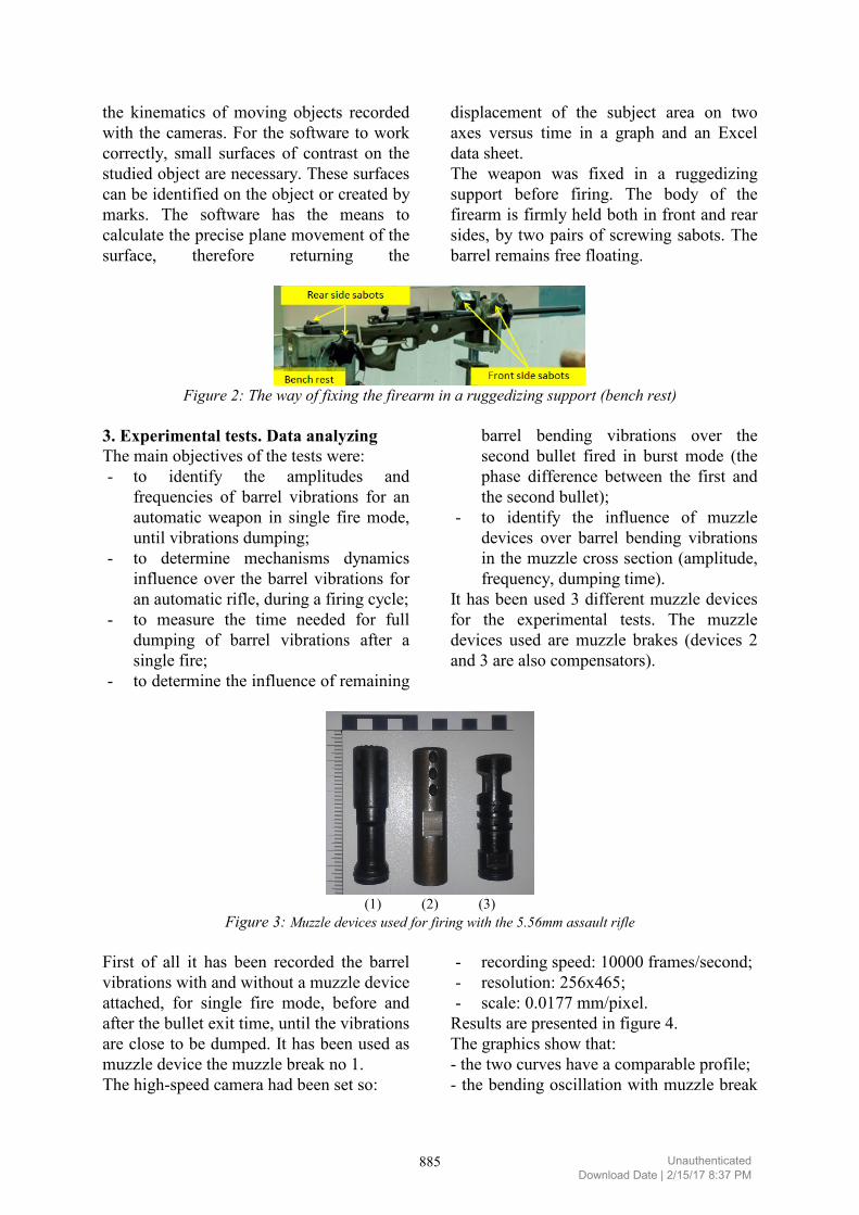
displacement of the subject area on two axes versus time in a graph and an Excel data sheet. The weapon was fixed in a ruggedizing support before firing. The body of the firearm is firmly held both in front and rear sides, by two pairs of screwing sabots. The barrel remains free floating.
Figure 2: The way of fixing the firearm in a ruggedizing support (bench rest)
3. Experimental tests. Data analyzing The main objectives of the tests were: - to identify the amplitudes and
frequencies of barrel vibrations for an automatic weapon in single fire mode, until vibrations dumping;
- to determine mechanisms dynamics influence over the barrel vibrations for an automatic rifle, during a firing cycle;
- to measure the time needed for full dumping of barrel vibrations after a single fire;
- to determine the influence of remaining
barrel bending vibrations over the second bullet fired in burst mode (the phase difference between the first and the second bullet);
- to identify the influence of muzzle devices over barrel bending vibrations in the muzzle cross section (amplitude, frequency, dumping time).
It has been used 3 different muzzle devices for the experimental tests. The muzzle devices used are muzzle brakes (devices 2 and 3 are also compensators).
(1) (2) (3)
Figure 3: Muzzle devices used for firing with the 5.56mm assault rifle
First of all it has been recorded the barrel vibrations with and without a muzzle device attached, for single fire mode, before and after the bullet exit time, until the vibrations are close to be dumped. It has been used as muzzle device the muzzle break no 1. The high-speed camera had been set so:
- recording speed: 10000 frames/second; - resolution: 256x465; - scale: 0.0177 mm/pixel.
Results are presented in figure 4. The graphics show that: - the two curves have a comparable profile; - the bending oscillation with muzzle break
885 UnauthenticatedDownload Date | 2/15/17 8:37 PM

has an absolute maximum of 2.469mm (positive), compared to 3.699mm (negative) without muzzle break; - the maxima for the negative and positive displacement of the muzzle are almost equal in absolute values for the vibrations of the barrel with muzzle break, while the negative displacement is 1.6 times higher in
absolute value than the positive one for the vibrations of the barrel without muzzle break, showing that bending vibrations of the barrel in the muzzle section is balanced by the muzzle device; - 0.2ms after bullet exit, the two curves are very similar, with approx. 0.2mm difference of phase;
-0.1 0 0.1 0.2 0.3 0.4 0.5 0.6-4
-3
-2
-1
0
1
2
3
(1) (2)
Figure: 4 (1) Plane trajectory of the muzzle of a 5.56mm assault rifle without muzzle device, single fire (2) Comparison between the vertical displacement of the muzzle of a 5.56mm assault rifle without
muzzle device (red line) and with muzzle device no 1 (blue line), single fire
- the vibrations are not dumped 0.5s after bullet exit time (the end of data acquisition) but extrapolating they will most probably be almost completely dumped in less than 1s after bullet exit time, meaning that they influence very little the shooter in the process of aiming and shooting the next bullet.
Second of all, it have been fired 2 bullets in burst mode without muzzle device and with each of the 3 muzzle devices. The settings used for the camera are: - recording speed: 10000 frames/second; - resolution: 256x465; - scale: 0.0177 mm/pixel.
Results are presented in figure 5
(a) (b) (c) (d)
886 UnauthenticatedDownload Date | 2/15/17 8:37 PM

-0.05 0 0.05 0.1 0.15 0.2 0.25 0.3 0.35 0.4 0.45-4
-3
-2
-1
0
1
2
3
4
t [s]
y [m
m]
No muzzle deviceMuzzle break 1Muzzle break 2Muzzle break 3
(e) Figure: 5 Vertical displacement vs. time for the muzzle of a 5.56mm assault rifle with (a) no muzzle device, (b)
muzzle device no 1, (c) muzzle device no 2, (d) muzzle device no 3 – 2 cartridges burst fire (e) Comparison between the vertical displacements of the muzzle
The bending oscillation with muzzle break no 1, has an absolute maximum of 3.979mm (positive), compared to 3.826mm (negative) without muzzle break. The other two devices generated values between these points. The maxima for the negative and positive displacement of the muzzle are almost equal in absolute values for the vibrations of the barrel with one specified muzzle break, than the one for the vibrations of the barrel without muzzle break, showing that
bending vibrations of the barrel in the muzzle section are balanced by the muzzle device. From the graphics it is obvious that every muzzle device influences the vibratory pattern of the barrel bending vibrations in the muzzle cross section differently. Considering the desired effect on the firing, sound attenuation, hidden flame, mitigation or strengthening of recoil, muzzle device configuration will be different.
Acknowledgements
This paper has been financially supported within the project entitled “Horizon 2020 -Doctoral and Postdoctoral Studies: Promoting the National Interest through Excellence, Competitiveness and Responsibility in the Field of Romanian Fundamental and Applied Scientific Research”, contract number POSDRU/159/1.5/S/140106. This project is co-financed by European Social Fund through Sectorial Operational Programme for Human Resources Development 2007-2013. Investing in people!
References
[1] *** Rheinmetall Handbook on Weaponry, Dusseldorf, 1982 [2] Roşca Aurel, Automatic weapons – The resultant vibration of the barrel. The influence on
the firing precision, Military Technical Academy Press House, Bucharest, 2002 [3] Piersol Allan and Paez Thomas, Harris’ Shock and vibration Handbook, 6th edition,
McGraw Hill Handbooks, 2009
887 UnauthenticatedDownload Date | 2/15/17 8:37 PM