Embed Size (px)
Citation preview

The aLife Home System

The aLife Home System
Home automation with a different approach
Market flooded The all take the same approach: GUI’s that
wait for user input aLife is even driven based on
Temperatures Security Energy

aLife Example Event

Project Goals And Objectives
Create a “smart”, customizable, all-in-one system
Little to no learning curve Focus on passive user control Can integrate with most homes Simple configurations Easily integrates with existing smart
home technologies Low cost

Project Block Diagram
Zigbee Base
Base Station

Remote Module

Remote Modules - Communications
Module Communication Network– Wireless Zigbee More reliable, robust than wired Flexibility in module installation location Acceptable data rate (up to 250kbps) Acceptable transmission range (up to 75m) Open source, abundance of cheap
hardware and software available

Remote Modules – Block Diagram
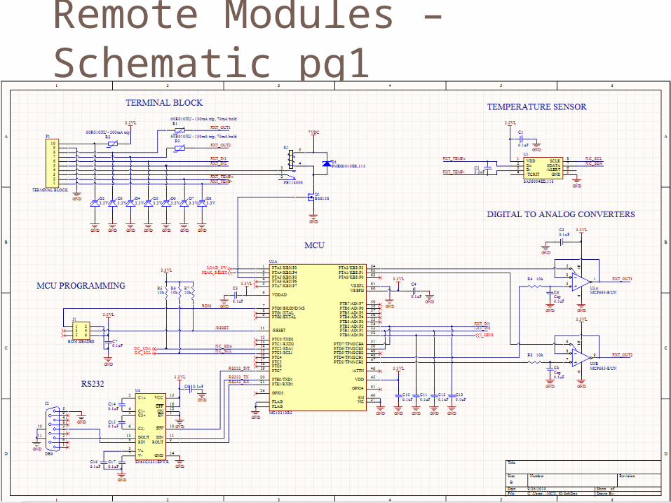
Remote Modules – Schematic pg1

Remote Modules – Schematic pg2

Remote Modules – Schematic pg3

Remote Modules – Power Supply
Power Supply Requirement Specifications 3.3VDC output 9-15VDC input range Source >= 250mA Output ripple <= 20mV peak to peak Work off of both 120VAC and battery Efficiency >= 80% Transient protection

Remote Modules – Power Supply
Power Supply Implementation: National Semi LM2841XMK-ADJL switching
buck DC-DC converter 3.3VDC output voltage 4.5VDC – 42VDC input range 2mV peak to peak output ripple
(simulation) 83% efficiency under simulation 120VAC to 12VDC step down SMBJ12A TVS, breakdown at 13.3VDC

Remote Modules – Power Supply

Remote Modules – MCU
MCU Requirement Specifications: Operate at >= 15MHz Have >= 32kB built in FLASH, >= 2kB built
in RAM Have at least: 2ADC, 1 UART, 1 12C, 2
PWM, 2 digital inputs, 2 digital outputs Built in ZigBee transceiver Available ZigBee Consumer protocol stack

Remote Modules – MCU
MCU Design Implementation Freescale MC13213R2
20 MHz 60kB FLASH, 4kB RAM Built in ZigBee transceiver BeeStack Consumer RF4CE compliant ZigBee
protocol stack available for free from Freescale 8x ADC, 2x UART, 1x I2C, 5x PWM, 22x GPIO
Program firmware in C using CodeWarrior IDE

Remote Modules – MCU

Remote Modules – Base Comms
Communication with Android Base Requirement Specs Must use a standard that is compatible with
both Android base and remote module hardware
Implementation RS232 using TI SN65C3221EPWR
transceiver Up to 1M baud rate 15kV ESD protection No hardware handshaking

Remote Modules – Base Comms

Remote Modules – Type 1 Functions
120VAC Power Sensor Requirement Specifications Measure up to 1800W (max power rating
for a standard wall outlet) Resolution down to 5W at 3% accuracy Less that 0.1 Ohm impedance on AC line Electrical isolation between AC and digital
side Surge protection on AC side Simple firmware calculation of power

Remote Modules – Type 1 Functions
Power Sensor Design: Allegro Micro ACS709LLFTR-20BB-T Hall
effect based AC current sensor Measures up to 3200W 1.1 mOhm series AC impedance AC isolation, 2100VAC surge protection
Theoretical resolution down to 3W at 2% accuracy (still needs to be tested)

Remote Modules – Type 1 Functions
AC peak detector circuit on output of power sensor makes power calculations in firmware simple
On Semi MC33072ADR2G instrumentation amplifier for precision performance
Gain controlled via ADI AD5241BRZ1M 1M Ohm, 256 step digital Pot for power ranging from 3W up to 1700W

Remote Modules – Type 1 Functions

Remote Modules – Type 1 Functions
Temperature Sensor Requirement Specs: Accurate to within +/- 2 degrees Celsius Range of -30 to +100 degrees Celsius I2C interface Remote temperature sensor loop
Implementation NXP SA56004ED,118 temperature sensor Meets the above requirements

Remote Modules – Type 1 Functions

Remote Modules – Type 2 Functions
Digital to Analog Converters Requirement Specs: Be able to change from gnd to 3.3V in 5ms Output can drive at least +/- 50mA
DAC Implementation - PWM fed into low pass op amp circuits using Micron MCP665-E/UN dual op amp chip Can change from gnd to 3.3V in 3ms Output can drive +/- 90mA

Remote Modules – Type 2 Functions

Remote Modules – Type 2 Functions
Terminal Block and Relay Requirement Specifications PTC protection for all outputs and power TVS protection for all I/O except relay Relay that handle 10A
Implementation 70mA hold, 130mA trip PTCs 400W TVS, clamp at 7.3V 10A relay

Remote Modules – Type 2 Functions

Remote Modules – ZigBee Transceiver
ZigBee Transceiver Requirement Specifications Transmission range of >= 30m ZigBee Consumer RF4CE compliant protocol
ZigBee Transceiver Design Transmission range still unknown pending
antenna development Will use Freescale’s BeeStack Consumer
RF4CE compliant protocol stack, specifically designed for this MCU
Single port antenna design to minimize components

Remote Modules – ZigBee Transceiver

Remote Modules – PCB
PCB implementation: We will generate a layout from our
schematic in Altium and manufacture our own custom PCBs with the following target specs: 2-4 layer boards 3”x3” or smaller outside dimensions Double sided component placement

Remote Modules – Successes Remote Module Successes:
Successfully simulated power supply design Successfully tested DACs I have experience successfully working with
Freescale CodeWarrior IDE and HCS08 MCUs (same core as MC13213)

Remote Modules – Difficulties Remote Module Difficulties:
Due to the size and complexity of the surface mount ICs, it is impossible to prototype the modules before ordering PCBs
Wanted to implement MCU controlled light dimmer, turned out not to be worth the time, effort, and cost
The current sensor may not have accurate output response at low power (<=100W)
Working with the ZigBee protocol stack is an unknown process

Base Station Hardware

Design decision - Functionality
Need a board to be able to run the android operating system.
Has to be able to handle multiple clients accessing it at the same time (up to 5).
Supports serial communication to interact with the Zigbee devices on the network

Design decision - Practicality
It’s a wall mounted unit, so the overall weight should be less than 5 pounds
Dimensions should be less than 50 cm x 50 cm x 10 cm
Needs to be powered off a wall outlet LCD should be bigger than 2 inches to be
considered easy to interact with

Microcontroller
NXP LPC3250

NXP LPC3250 Specifications
Processor – ARM926EJ-S core Runs at 266 MHz Meets the minimum android system
requirements of 200 MHz Memory – **Find data** Ethernet Connectivity Serial Interfaces
7xUART, 2xI2C, 2xSPI, 2xSSP, 2xI2S

Picture
Need to add dimensions 66 x 48 mm 3.15-3.3V powering

QVGA Base Board
Embedded Artists LPC3250 Base Board 240 x 150 mm

LPC3250 Baseboard specifications
3.2 inch QVGA TFT LCD with touch screen panel
Ethernet connector Powering
Can be USB powered 9-15V DC
Other random ones Built in speaker

Serial Communication
Main way of transferring data from the base station to the network
Problem – native android doesn’t support the communication over serial ports
Had a few choices for solving the problem, using either C or Unix.

Serial Communication: C vs. Unix
Final Decision:C, because we can make use of a program called JNI which can add C programs as libraries to a Java program and allows us to import the serial data directly into Java

Format for the C code

Difficulties/Successes
Difficulties Serial communication not native to android Dealing with the Zigbee protocol stack
formatting when reading and processing incoming data
Finding a way to case and mount the board Successes
Our board contains a bootable version of android on it

Base Station Software

Specifications and Requirements
Functional:
Base station must be able to accept up to 5 simultaneous service request on a first come first serve basis
Multiple request to service the same notification must only be serviced once
Must be able to add/remove/update a row in database with 98% reliability
Security:
All user must have unique login; Allowed 5 unsuccessful attempts before lockout
Only registered remote client devices may have service request fulfilled by the base station
Notifications:
All notifications must have a unique notification ID Users shall only receive notifications that they are registered to receive

Design Approach and Implementation
V-Model Proven and well structured Allows for redesign
Android Operation System Supports notifications Supports secure socket communication Database support
Eclipse IDE w/ Android Development Tools (ADT) Plug-in Free Best support for Android Development
V – Model

Research and Design DecisionsDatabase Management System
(DBMS)IBM's DB2 Express-C
Free XML database and relational database server
system Available for Linux (32/64 bit), Windows (32/64 bit),
Solaris (64 bit Intel), and Mac OS X (64 bit Intel) Allows your server to use up to 2 Cores on your
computer (1 CPU), up to 2 Giga Bytes of RAM, places no database size limits, no connection limits, and no user limits

Research and Design DecisionsDatabase Management System
(DBMS)
SQLite Free Embedded relational database management
system Not a standalone process, it is an in-process
library that implements a self-contained, serverless SQL database engine
Avoids inter-process communication making it faster than the more traditional models
Natively supported by the Android Platform

Research and Design Decisions Database Management System
(DBMS)
Why SQLite? Extensive native support provided by Android
platform. Will run on Base Station, no need for additional
hardware No need for purchase server space. Relatively fast compared to other DBMS

Software Block Diagram

Software Block Diagram – Background Services
Fields: PowerNotif (Bolean): Field tells whether a powered device notification is set up SecurityNotif (Bolean): Field tells whether a security device notification is set up ControlNotif (Bolean): Field tells whether a control device notification is set up ActiveDevices(Device [ ]): Array of active devices in the network RequestedService (String): String representation of a request
Methods: BaseStation ():Constructor to create the GUI interface for our system. getActiveDevices(): Takes in no parameters. Returns all active devices in database. addDevice(Device X): Adds specified device to network and database. No return. removeDevice(Device X): Removed specified device from network and database. No
return. setNotifications(): Takes no parameters. Sets all initial notifications booleans. These will
dictate which notifications will be checked for continuously throughout the program. pollDevices(ActiveDevices): Takes in all active devices and updates their information in
the database tables. Returns nothing. socketParser (ByteStream): Takes in a socket byte stream and returns the requested
service in string format. requestService (Device X, RequestService): This method will take in a device and service
request and will fulfill the said service. Returns nothing.

Software Block Diagram – Devices Class
Fields: ID (Int) : Device's ID Name (String): Name provided by user for device Status (Boolean): Provides status of device, on or off
Methods: getID(): Takes in no parameters. Returns an Int, the value of the devices ID. setID(Int ID): Takes in an Int and updates ID field. Does not return anything. getName(): Takes in no parameters. Returns a String, the value of the devices
Name. setName(String name): Take in a String and update Name field. Does not return
anything. getStatus(): Takes in no parameters. Returns Status of device setStatus(Boolean Status): Takes in a boolean and updates Status of device. Does
not return anything.
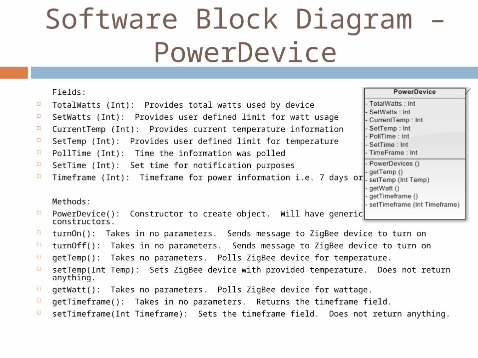
Software Block Diagram – PowerDevice
Fields: TotalWatts (Int): Provides total watts used by device SetWatts (Int): Provides user defined limit for watt usage CurrentTemp (Int): Provides current temperature information SetTemp (Int): Provides user defined limit for temperature PollTime (Int): Time the information was polled SetTime (Int): Set time for notification purposes Timeframe (Int): Timeframe for power information i.e. 7 days or 30 days
Methods: PowerDevice(): Constructor to create object. Will have generic and specific constructors. turnOn(): Takes in no parameters. Sends message to ZigBee device to turn on turnOff(): Takes in no parameters. Sends message to ZigBee device to turn on getTemp(): Takes no parameters. Polls ZigBee device for temperature. setTemp(Int Temp): Sets ZigBee device with provided temperature. Does not return
anything. getWatt(): Takes no parameters. Polls ZigBee device for wattage. getTimeframe(): Takes in no parameters. Returns the timeframe field. setTimeframe(Int Timeframe): Sets the timeframe field. Does not return anything.

Software Block Diagram – SecurityDevice
Fields: PowerNotif (Bolean): Field tells whether a powered device notification is set up SecurityNotif (Bolean): Field tells whether a security device notification is set up ControlNotif (Bolean): Field tells whether a control device notification is set up ActiveDevices(Device [ ]): Array of active devices in the network RequestedService (String): Integer representation of a request
Methods: BaseStation ():Constructor to create the GUI interface for our system. getActiveDevices(): Takes in no parameters. Returns all active devices in database. addDevice(Device X): Adds specified device to network and database. No return. removeDevice(Device X): Removed specified device from network and database. No
return. setNotifications(): Takes no parameters. Sets all initial notifications booleans. These will
dictate which notifications will be checked for continuously throughout the program. pollDevices(ActiveDevices): Takes in all active devices and updates their information in
the database tables. Returns nothing. socketParser (ByteStream): Takes in a socket byte stream and returns the requested
service in string format. requestService (Device X, RequestService): This method will take in a device and service
request and will fulfill the said service. Returns nothing.

Software Block Diagram – ControlDevice
Fields: SetTime(Int): Set time for notification purposes
Methods: ControlDevice(): Constructor to create object. Will have generic and specific
constructors. turnOn(): Takes in no parameters. Sends message to ZigBee device to turn on turnOff(): Takes in no parameters. Sends message to ZigBee device to turn on

Database Structure
The SQLite database will be utilized to store information about current users, devices, power history, notification history, and notification set ups. Each of these elements will be have their own table in our database with their own specified fields.

Successes and Difficulties
Current Difficulties Need to move background services from
threads to background activities Communication with low level serial ports
Current Success Successfully able to connect TCP Sockets
and pass information Creating the user interface for the base
station software

Remote Client Device (RCD)

Specifications and Requirements
Reliability No crashes 90% Notification Rate with connection 100% over time
Usability Easy to navigate menus
Unobtrusive Notifications only when needed

Specifications and Requirements
Android Phone Secure Connection Fast notifications
<10 sec with a connection Data over WiFi or Cell Network

Research and Design Decisions
Minimal focus on control
Notifications based on events Untapped market Cost savings

Notifications Packet Structure
Type 1 (Power)
Type 2(Power)
Type (Power)
Type 4 (Temperature)
Type 5 (Temperature)
Notification type
Notification type
Notification Type
Notification Type
Notification Type
Notification Level
Notification Level
Notification Level
Notification Level
Notification Level
Notification ID# Notification ID# Notification ID# Notification ID# Notification ID#
Button 1 Text Button 1 Text
Button 2 Text Button 2 Text
Button 3 Text Button 3 Text
Current Temp
Current Set Point
Current HVAC Mode
Page Flip Page Flip Page Flip Page Flip Page Flip
Display State with Control Options
Display History with Notification Options
Display History with Notification Options
Display State with Control Options
Display History with Notification Options

Class Structures
Android Notification Service

Class Structures
aLife Menu System

Design Approach and Implementation
GUI

Successes and Difficulties
Tracking of phone IP Address Android version of Java

stuff
Jake

Budgeting
Base Station Embedded Artists LPC3250 OEM and QVGA
base board: $0.00 (on loan from Advantor Systems)
Remote Client HTC Dream Android smartphone: $0.00
(owned by a group member) Remote Modules – per module costs on
following table

Budgeting – Per Remote Module
Remote Modules Freescale MC13213 – $0.00 (sampled from
Freescale)
Item Type Manufacturer
Part Number Cost/1 Multiple
MCU Freescale MC13213R2 $0.00
Dual op amps Micron MCP665-E/UN $1.46
Temp Sensor NXP SA56004ED,118 $0.85
Relay Tyco PB114006 $1.18 2
Terminal Block Tyco 1-284093-0 $2.21
DC-DC Converter
National LM2841XMK-ADJL $3.90
Transformer Pulse BV030-7136.0 $3.36
Current Sensor Allegro ACS709LLFTR-20BB-T
$4.46
Instrum Amps On Semi MC33072AD $1.10
Digital Pot ADI AD5241BRZ1M $2.33
Balun Murata LDB212G4005C-001
$0.42
Crystal AVX CX3225SB16000E0FPZ25
$3.30
Misc $5.00

Budgeting – Remote Module Component Costs
Total per module: $30.75 Additional costs for ZigBee base module
RS232 transceiver – TI SN65C3221EPWR, $2.63
DB9 connector - Norcomp 171-009-113R911, $3.00
No terminal block – -$2.21 Bare PCBs (6 sq inch) – $42.75 each Total cost of 4 remote modules: $297.42
**Doesn’t include manufacturing costs!!

Budgeting - Summary
Total budge allowance - $600 Base Station - $0.00 Remote Client - $0.00 Remote Modules - $297.42 (+mfr costs)
Total = $297.42 (plus mfr costs) Remaining Budget = $302.58 Still way under budget!!

Current Progress

Immediate plans for success
Construct the Zigbee interface to the base station and start working on the peripheral devices
Finish Zigbee layout and get boards manufactured
Finish up with the GUI (Remote Client) and start working on formatting notifications
Start setting up user accounts and formatting the database
Work on TCP connection between remote client and basestation

Questions
Any questions or comments?