Embed Size (px)
Citation preview

The Advanced Photon Source RF Systems
-- Performance and Upgrades –2012-2014
Doug HoranAdvanced Photon SourceRF GroupASD SeminarNovember 12, 2014

APS Storage Ring RF Topology
ASD Seminar -- November 12, 2014
Waveguide switching system provides twelve modes of operation with different combinations of rf systems
Routine storage ring operation is 103mA maximum stored current in “top-up” mode
Requires two klystrons driving storage ring, each operating at ~ 675kW CW
“Offline” rf stations are in diode, 70kV/5A
2
RF4RF1 RF2 RF3

APS Booster RF Topology
ASD Seminar -- November 12, 2014
Uses one 1-MW klystron (RF5) operating at 400kW peak, ~ 120kW average power
Waveguide switching system allows storage ring station RF3as a back-up to RF5 -- successfully tested on 7/15/14
3
RF5

PAR Accumulator Ring -- RF System Topology
ASD Seminar -- November 12, 2014
▪ 9.77 MHz▪ 4kW CW▪ YU-106 triode ▪ Grounded grid▪ Main/backup power amplifiers
4
Fundamental System
▪ 117.3 MHz▪ 3kW peak▪ 3CX3000A7 triode ▪ Grounded grid▪ Main/backup power amplifiers
Harmonic System
1 2
3
RF System Reliability Statistics
ASD Seminar -- November 12, 2014
5

RF System Downtime – FY2012
Main RF Downtime Causes:
→ 24v linear power supply failed in rf power monitor
→ Focus magnet powersupply tripped on RF2,and operator error inclosing 13.2kV switch
ASD Seminar -- November 12, 2014
6
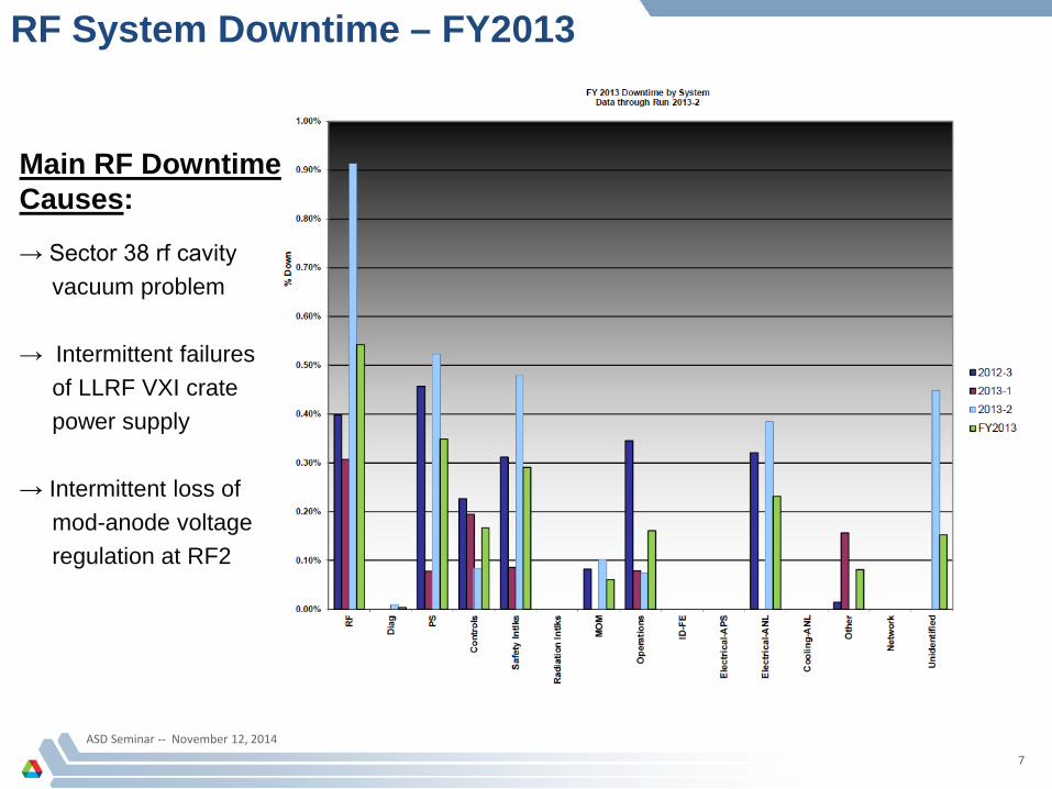
RF System Downtime – FY2013
ASD Seminar -- November 12, 2014
7
Main RF Downtime Causes:
→ Sector 38 rf cavityvacuum problem
→ Intermittent failuresof LLRF VXI cratepower supply
→ Intermittent loss ofmod-anode voltageregulation at RF2

RF System Downtime – FY2014
ASD Seminar -- November 12, 2014
8
Main RF Downtime Causes:→ RF3 crowbar trips
→ RF3 klystron sidebands
→ Intermittent access door interlock switch
→ Vacuum trips at Sector37 rf cavities
→ Intermittent hv cable
→ Klystron instabilities and waveguide arcing at RF3
RF:
→ 0.21% downtime
→ 544.5 hours Mean Time Between Faults

RF System Problemsand
Hardware Failures
ASD Seminar -- November 12, 2014
9

Intermittent Loss of Mod-Anode Voltage Regulation – cause of many beam losses
ASD Seminar -- November 12, 2014
10
▪ 18 years of X-rays fromtetrodes damaged teflonwire used to feed heaterpower to the tetrodes
▪ Caused intermittent shortcircuit of heater power
▪ Damage found in all rf stations
▪ Wiring was replaced
TETRODE SOCKET
BRAID PULLED
BACK

Cause of Crowbar Trips –Failed 50kV Vacuum Switch
▪ Two 50kV switches used inseries at low end of crowbar test wire
▪ Switch breaks down in open position, causing intermittent crowbar trips
▪ No longer available from originalmanufacturer – found second source
ASD Seminar -- November 12, 2014
11

ASD Seminar -- November 12, 2014
12
Sector 36/Cavity #3 “Hot Tuner”
TUNER PISTON
THERMOCOUPLES
▪ RF Finger temperature suddenly 25-40ºC warmer with hybrid fill pattern – but normal with 324 singlets
▪ Tuner inspection at shutdown shows“plating” on piston………gold?
▪ Tuner was replaced……….problem didn’treturn
RF FINGER CONTACTS

Sector 38 RF Cavities –Mysterious Vacuum Problem
ASD Seminar -- November 12, 2014
13
▪ Vacuum pressure in entire sector of cavities startedto rise suddenly at the end of post-shutdown beam conditioning -- highest pressure in cavity 2
▪ Pressure continued to rise as the run progressed,and vacuum interlock trip points had to be raised to stay in operation
▪ Multiple helium leak tests showed no leaks fromatmosphere
▪ Residual gas analyzer indicated traces of chlorineand fluorine
▪ Tried conditioning during shutdown, but pressureeventually increased to the point that we could not run rf
STORAGE RING BEAM CONDITIONING
START OF PRESSURE
RISE
PRESSURE INCREASE DURING RUN

Sector 38 RF Cavities –Mysterious Vacuum Problem
ASD Seminar -- November 12, 2014
14
▪ Parts were “shot-gunned” – Couplers, tuners, andHOM dampers were removed from cavities 1 and2 – all parts except for one HOM damper were replaced with new components
▪ Vacuum pressure quickly returned to normal levels -- low-mid E-9 Torr
▪ Cavities were re-conditioned back to operatinglevels in approximately three days
▪ Pulled parts were installed in RF Test Stand cavityindividually to determine which component wasoutgassing
▪ Cavity #2 tuner was the source of gas

High-Voltage Cable/Socket Failures
ASD Seminar -- November 12, 2014
15
▪ Connector arcing causes crowbartrip and damage to plug and socket
▪ Causes:→ Plug insertion force too low→ Foreign objects in socket
→ Insufficient insulating grease→ Intermittent contacts on plugs
POOR SOLDER CONNECTION
ON TIP

Multiple Problems with RF3Trouble Started With a Klystron Change!
ASD Seminar -- November 12, 2014
16
▪ Longest living klystron at APS wasretired at RF3:
→ EEV K3513 s/n 01→ Retired at 81,209 filament hours→ 14 years of service with no problems
or instabilities
▪ Replaced with rebuilt spare
▪ Immediate issues with poor efficiency, crowbar trips, and sideband instabilities
▪ RF3 was unavailable for an entire runwhile troubleshooting was in progress
▪ Multiple causes found:→ Significant cathode voltage readback error→ Intermittent HV connectors→ Waveguide arcing
EEV s/n 01 REMOVED FROM RF3

Waveguide Arcing at RF3
ASD Seminar -- November 12, 2014
17
▪ Using the EEV klystron, the system would run at ≈ 700kWfor almost an hour, then trip on waveguide arc
▪ Loud noises coming from the 2nd-harmonic damper
▪ After four or five arc trips togather data, we shut the system down
▪ Waveguide was dismantled for inspection during the maintenance shutdown
2nd HARMONIC DAMPER AT RF3
200-WATT LOADS
COUPLING PROBES

Waveguide Arcing at RF3
ASD Seminar -- November 12, 2014
18
ALL SIX HARMONIC DAMPER LOADS DESTROYED
DAMPER PROBE BURNED OFF
ARCING DAMAGE TO HARMONIC DAMPER PROBES
Severe damage to harmonic
damper pickup probes
and terminating
loads
Cause: Excessive 2nd
harmonic output from klystron

EEV s/n 01 Caused Waveguide Arcing at RF3
ASD Seminar -- November 12, 2014
19
▪
▪ Klystron produced excessive 2nd-harmonic power…..why?
▪ Klystron rf cavity tuning nuts were found to be loose on cavities 3 and 4
▪ EEV s/n 01 retired permanently!
▪ Replaced with new Thales klystron s/n 089048
→ Efficiency at 650kW output is ~ 4-5% lower than other Thales klystrons
→ Some sideband instabilities, but avoidable with careful adjustment
EEV s/n 01
EEV s/n 01 was brought out of retirement and re-installed in RF3to help troubleshoot system

ASD Seminar -- November 12, 2014
20
Klystron Sideband Instabilities ▪ A common problem with Thales TH2089A
▪ Two types: → Back-streaming electrons -- Thought to be caused
by back-streaming electrons from the collector accelerated towards the cathode by output cavitygap voltage. Sideband frequency is typically351.93MHz ± the difference between resonantfrequency of cavity 1 and cavity 2: ≈ 2.2MHz
→ Cavity multipactor – Caused by multipactor in the first or second rf cavities. Sideband frequencyis typically 351.93MHz ± 1MHz or less
▪ Sidebands can exist at fixed frequencies,or drift in frequency randomly
▪ Can be controlled by careful adjustment ofcathode voltage, output match (circulator bias),and rf drive level

ASD Seminar -- November 12, 2014
21
Shorted MOV in Mod-Anode
▪ The shorted MOV effectively reducedthe plate load resistance of onetetrode from 225kΩ to ≈ 22kΩ
▪ The power dissipated by the tetrodebegan to heat the 400 gallons of oil in the tank…………until the systemtripped on a “mod anode overtemp”fault
OVERHEATED TETRODE
MOV’s

ASD Seminar -- November 12, 2014
22
Failed Banana Plug Connection inRF3 Transformer-Rectifier Set
▪ During routine maintenance, tracechemical analysis of the T-R set oildetected chemical markers for arcingin the oil
▪ Problem traced to a partially-insertedbanana plug used as the bottom connection to a rectifier stack, located under 3,000 gallons ofinsulating oil
▪ The plug eventually overheated andbegan arcing under load
DAMAGED PLUG AND MATING SOCKET

Failure of Re-tuned Philips YK1350 Klystron in RF5
ASD Seminar -- November 12, 2014
23
▪ Retired from CWDD project in 1995
▪ Re-tuned from 352.21MHz to 351.93MHzin 2009 and tested to 1MW cw in test stand with no problems
▪ Installed at RF5 in January 2014
▪ Operated normally for first run of 2014 withno problems
▪ Coming out of the May 2014 maintenance shutdown, the klystron beam current became unstable
▪ All attempts to stabilize the gun perveance were futile
▪ The Philips klystron was removed from RF5in June 2015 -- the original klystron was re-installed
BURN MARK ON COIL
WATER FITTING

Harmonic PAR Driver Amp Failure
ASD Seminar -- November 12, 2014
24
▪ 117.3MHz/500-watt cwcommercial amplifier
▪ Failed during bench testing into load
▪ Input and output leads were disconnected with dc power applied
▪ Suspected instability indesign
▪ Not repairable

Destruction of a Mod-Anode Tetrode Tube Due to a Malfunctioning Crowbar
ASD Seminar -- November 12, 2014
25
CROWBAR FAILED TO FIRE IN RESPONSE TO A HIGH VOLTAGE FAULT

T-R Set Resistor Failure
ASD Seminar -- November 12, 2014
26
▪ Found during routine measurement of RF4capacitor bank
▪ Measured 7.5µF ratherthan expected 8.1µF
▪ Found resistor in serieswith capacitor open onone end
▪ Failed due to age, temperature, crowbar event stress, oil…....???
OPEN TERMINATION

Potential Problem? -- Water in 13.2kVAC and 1400VAC
Underground Conduits
ASD Seminar -- November 12, 2014
27
▪ Conduits run between outdoor transformer padsand rf building
▪ Cables are almost 20 yearsold
▪ Possible failure due tofreeze-thaw stress?
RF System Upgrades and
Improvements
ASD Seminar -- November 12, 2014
28

RF System Hardware Upgrades 2012-2014
ASD Seminar -- November 12, 2014
29
REPLACEMENT OF ORIGINAL T-R SET FILTER BANK CAPACITORS
NEW PLC CONTROL SYSTEM TO REPLACE ORIGINAL OBSOLETE CONTROLS
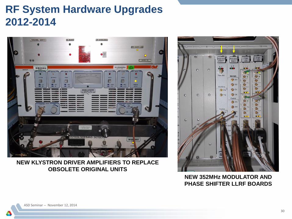
RF System Hardware Upgrades 2012-2014
ASD Seminar -- November 12, 2014
30
NEW KLYSTRON DRIVER AMPLIFIERS TO REPLACE OBSOLETE ORIGINAL UNITS
NEW 352MHz MODULATOR AND PHASE SHIFTER LLRF BOARDS

ASD Seminar -- November 12, 2014
31
RF System Hardware Upgrades 2012-2014 -- Harmonic PAR Output Isolator
▪ 117.3MHz/4kW average rating
▪ Provides >20dB isolation between amplifiers and cavity
▪ Amplifiers can be tuned for best efficiency with minimum effect on cavity resonance
▪ Cavity can be operated off-resonance for physics reasons without stressing amplifiers with reflected power
▪ Switch to back-up amplifier now causes minimal change in cavity tuning loop operating point
FULL POWER TEST
ISOLATOR INSTALLED

Conversion to Solid State High Voltage Switch in Linac Modulators
ASD Seminar -- November 12, 2014
32
▪ Presently installed in four out ofthe six Linac modulator systems
▪ Replaces expensive consumable thyratron tube
▪ Provides improved performance,reduced complexity, improved reliability, and long-term operatingcost savings

ASD Seminar -- November 12, 2014
33
Replacement of Linac ModulatorPFN Capacitors
▪ Presently installed in four out ofthe six Linac modulator systems
▪ Replaces original capacitors thathave reached the end of theirexpected operating lifetime
▪ Provides improved performanceand long-term reliability

ASD Seminar -- November 12, 2014
34
Replacement of Linac ModulatorPLC Control Systems
▪ Project completed at all six Linac modulators
▪ Replaced obsolete and un-supportedcathode ray tube touch screen monitors with LCD touch screens
▪ Provides improved reliability and long-term serviceability
ASD Seminar -- November 12, 2014
35
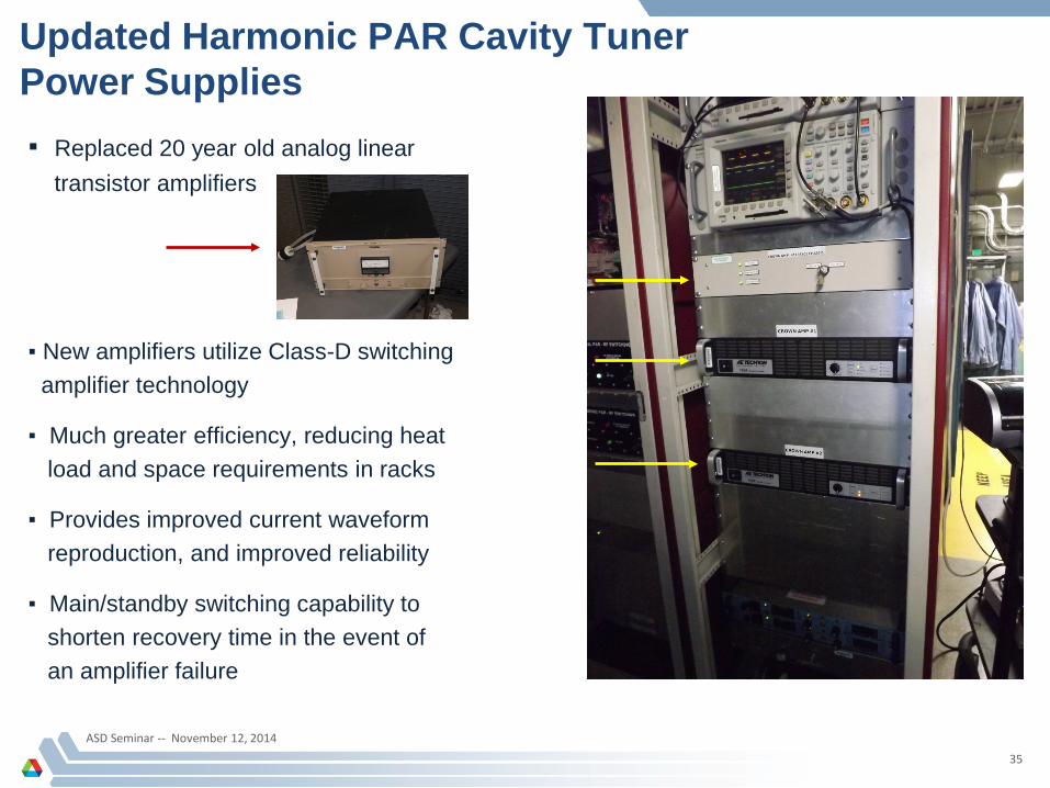
Updated Harmonic PAR Cavity TunerPower Supplies▪ Replaced 20 year old analog linear
transistor amplifiers
▪ New amplifiers utilize Class-D switchingamplifier technology
▪ Much greater efficiency, reducing heatload and space requirements in racks
▪ Provides improved current waveform reproduction, and improved reliability
▪ Main/standby switching capability toshorten recovery time in the event of an amplifier failure
ASD Seminar -- November 12, 2014
36
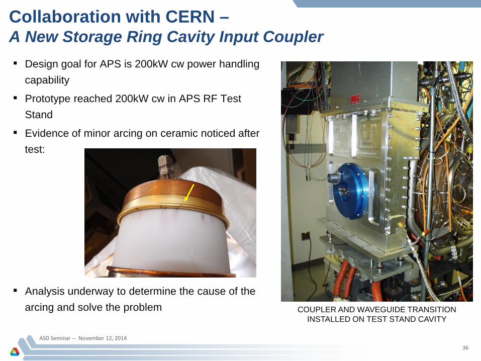
Collaboration with CERN –A New Storage Ring Cavity Input Coupler▪ Design goal for APS is 200kW cw power handling
capability
▪ Prototype reached 200kW cw in APS RF TestStand
▪ Evidence of minor arcing on ceramic noticed aftertest:
▪ Analysis underway to determine the cause of the arcing and solve the problem COUPLER AND WAVEGUIDE TRANSITION
INSTALLED ON TEST STAND CAVITY

ASD Seminar -- November 12, 2014
37
Solid State RF Power Development at APS –New 9.77MHz/1kW Driver Amplifier for PAR
▪ Design to replace 20-year old drivers
▪ Uses one Freescale 1.25kW push-pull LDMOS transistor package
▪ Broadband transformer matching for simplicity
▪ Air cooling

The RF Group
ASD Seminar -- November 12, 2014
38
The people who did all this work:
Roy Agner Mike Douell Mike Drackley Bruce Epperson David Jefferson Tim Jonasson George Kotsiopoulos Mark Moser William Yoder
Ali Nassiri Tim Berenc Dave Bromberek Alex Cours Eddy Goel Art Grelick Hengjie Ma David Meyer Terry Smith Gian Trento Geoff Waldschmidt