Embed Size (px)
Citation preview

ABC of Spray Painting Page 1
The ABC’s of SprayEquipment
A Working Guide to the Selection and Use of Spray Finishing Equipment
© ITW Finishing Technologies

Page 2 ABC of Spray Painting
1. Introduction
While this book examines thespray finishing operation and itsequipment from many viewpoints,there is still much more to belearned to become truly proficientat spray finishing.
The best way to becomeproficient at spray finishing is tojust do it! Many TechnicalColleges and Colleges of FurtherEducation have courses involvingspray finishing, a great way toimprove your skills. We have ourown Training facilities at Milperraand regularly conduct training courses there.
The “art” of the professionalspray finisher involves an in-depth knowledge of the paintsand coatings in use. Themanufacturers publishcomprehensive sales andtechnical literature on theirproducts. These publications areavailable from the materialdistributors and themanufacturers themselves, andwill provide you with considerabledetail. Many of these publicationsalso contain information ontechniques for surfacepreparation and applications.
Another important source ofinformation, particularly onequipment use and selection isyour local DeVilbiss sprayfinishing equipment distributor.No book could ever completelycover a specialist’s in-depthknowledge of equipment,techniques, maintenance andtroubleshooting.
Information is available frommany resources on the subject ofspray finishing. It is our hope thatthis book will provide you with a
start toward perfecting yourfinishing skills.
A recent addition to resourcesavailable to the spray finisher isthe World Wide Web. Manymanufactures are representedand question and answer forumsare available. Please visit ourwebsite at http//www.itwfinishing.com.au
2. About this book
This book has been totallyupdated from “The ABC’s ofSpray Equipment,” originallypublished by The DeVilbissCompany in 1954. It focuses onequipment and techniques forspray finishing.
The format of the original bookwas question-and-answer. Wehave retained that format in thisedition.
This book has now beensignificantly revised to take intoaccount the most recent productdevelopments and to reflect theequipment range available in ourmarket. It is organised around themajor components of a sprayshop - compressors, air controlequipment, hose, respirators,spray guns, material containers,pumps and spray booths. Thevarious gun types – Conventional,HVLP and Compliant, are allcovered. A thoroughunderstanding of the material inthis book - plus a lot of actualspray painting practice -should
enable you to handle most spraypainting situations.
Although we have made an effortto make this book as detailed andas complete as possible, beaware that the equipment andproduct systems used to illustratepoints are normally based onDeVilbiss technology. Thismanufacturer forms part of thethe Worlds largest supplier ofspray equipment as part of theITW Finishing Systems Groupand has the equipment andknowledge available to meetevery spray finishing requirement.
3. Table of Contents
1. Introduction 22. About this book 23. Table of Contents 24. Surface Preparation 25. Paint Preparation 36. Health and Safety 47. Air Compressors 4
Introduction 48. Air Control Equipment 5
Introduction 59. Masks and Respirators 810. Hose and Connections 10
Introduction 1011. Air Atomising Spray
Guns12
Introduction 12Spray Gun Types 12Part Identificationand Function
16
Operation 20Maintenance 23Troubleshooting 25
12. Fluid Feed 28Introduction 28Cups 28Tanks 29Pumps 31
13. Spray Booths 33Introduction 33
14. Conversion Tables 37
4. Surface Preparation
Without going into detail aboutthe specialist chemicalpreparation and treatment ofcertain substrate types, it shouldgo without saying that the surfaceto be coated must be in a suitablecondition ready to accept thesprayed material. This willnormally require the absence ofall loose particles, dust and scale.

ABC of Spray Painting Page 3
In the most common cases thiswill involve the ‘dusting down’ ofthe surface with a compressed airgun. More stubborncontamination may need the useof a bristle or wire brush while theworst situation may need theapplication of acid etching orparticle blasting.
Dust or loose particlecontamination will block thesprayed material from keying andadhering to the surface,producing peeling and adispleasing visual appearance.Likewise, any liquid or chemicalcontamination could also producethe same poor results (plus a fewmore).
In many production spray shopsthe preparation sequence will be:
1) lightly abrade surface to aidadhesion of sprayed coatingand remove surfacecontamination
2) thoroughly blow down withcompressed air gun toremove loose dust andparticulate contamination
3) Wipe with solventdampened, lint free cloth toloosen and remove liquidcontamination
4) Allow to fully dry beforecoating
Remember that moisture andwater will also act as a block andcontaminant and thereforecompressed air filters andseparators should be checkedand drained regularly to preventcontamination being sprayed ontothe surface with the coating.
Plastic parts may presentadditional problems, namelymould release agent and static.Mould release agent will normallybe removed by a single ormultiple solvent wipe. In the worstcase a high pressure detergentwash may be necessary. Due tothe charging properties of mostplastic materials the act of wipingor blowing the surface willgenerate static electricity that willattract particles of dust and dirt.Therefore use of an anti-staticcleaning liquid and/or de-ionisingair gun will be necessary.
If in any doubt about the correctpreparation prior to spraying,consult the Product Data Sheet orcontact the coatingsmanufacturers Technical SupportDepartment.
“The topcoat is only as good itssubstrate” - no amount of primeror paint will cover up a badlyprepared surface.
5. Paint Preparation
Today’s finishes are extremelycomplex chemical formulations.They include both solvent andwaterborne types as well as morespecialised formulations forspecial applications. Some onlyrequire the addition of solvents togive the proper spraying viscositywhile others require the additionof a second component at aprescribed ratio to obtainsprayable consistency. Manymodern coatings have hardenersor other chemicals, added tothem to insure correct colourmatch, gloss, hardness, dryingtime or other characteristicsnecessary to produce a first classfinish. Make sure you are familiarwith the specific Product DataSheets accompanying eachmaterial. Do not mix materialsfrom various manufacturers.Read and follow directionscarefully.
All finish materials must also besupplied with a Material SafetyData Sheet (MSDS). This dataprovides information on properhandling and disposal ofmaterials. Health and Safetylaws require that MSDS be kepton file by the user for immediatereference when necessary.
Always follow the manufacturer’sinstructions for preparing thecoating exactly. If you have anydoubts about how to proceed,don’t guess! Contact the supplierfor help. Improperly preparedcoating will never produce a goodresult.
The chief characteristic thatdetermines the sprayablility ofpaint and how much film may beapplied is its viscosity orconsistency. For professionalresults with most general purposecoatings, use a viscosity cup. It isa simple but very accurate way tomeasure the thickness of paint.With the cup, you can thin orreduce the paint to the preciseconsistency required by themanufacturer.
Always prepare paint in a clean,dust-free environment. Paint hasa remarkable ability to pick up

Page 4 ABC of Spray Painting
dirt. Use clean containers to mixthe paint in and always filter theliquid while pouring it into the gun,pump or tank. Dirty paint will notonly clog your spray gun, but itwill also ruin your paint job. Paintis never as clean as it looks.
6. Health and Safety
The spray shop is a dangerousplace. Every day we work withlung clogging dusts, poisonousand carcinogenic chemicals,highly flammable liquids and highpressure fluids and gasses. Inorder to maintain our health it isessential that correct proceduresare followed and that the correctprotective clothing and equipmentis used.
A strong pair of work boots andgood overalls are the basicequipment to which theappropriate extras need to beadded -
Lint free, disposable paperoveralls that can be thrown awayif they become heavily soiled withpaint
Gloves, nitrile or latex to avoidsolvent and paint coming intocontact with the hands
A suitable mask for the paint typebeing sprayed or the sandingoperation being carried out.
Safety glasses or Goggles toprotect you eyes from chemicalsplashes and flying debris
Ear plugs or defenders to preventdamage to your hearing by loudor continuous noise.
Don’t forget that other operationsin the wokshop can carry just asmuch hazard – masks, glovesand goggles are not onlynecessary for spraying andflatting.
It should go without saying thateating and drinking in an area fullof chemicals and dusts is notadvised and smoking shouldnever take place in any areacontaining flammable liquids such
as paint and solvents.
Disposal of waste paints andsoiled cloths is now a specialisedprocess that needs planning andmonitoring.
Consult your local area authorityfor details on the exact safetyrequirements for your processand paint shop.
7. Air Compressors
Introduction
All air tools, spray guns, sanders,etc, must be supplied with airwhich is elevated to higherpressures and delivered insufficient volume. The aircompressor compresses air foruse in this equipment and is amajor component of a spraypainting system. This chapter willexamine the various typesavailable.
Compressed air is measured onthe basis of volume supplied perunit of time (cubic feet per minuteor cfm) at a given pressure persquare inch or psi), referred to asdelivery. This is the actual airoutput of the compressor after itsefficiency is taken into account.Displacement is the output of airby a compressor at zeropressure, or Free Air Delivery.This is the theoretical air outputof the compressor before itsefficiency is taken into account.
1. What is an air compressor?
An air compressor is a machinedesigned to raise the pressure ofair from normal atmosphericpressure to some higherpressure, as measured in poundsper square inch (psi). Whilenormal atmospheric pressure isabout 14.7 pounds per squareinch, standard compressors willtypically deliver air at pressuresup to 150 psi.
Rule of thumbThe cubic feet per minute delivered byan electrically powered 2 stage pistonindustrial air compressor isapproximately 3 to 4 times the motor’shorsepower rating. (CFM = 3 to 4 xHP)
2. What types of compressorsare most common in sprayfinishing operations?
There are two common types; thepiston-type design and the rotaryscrew design.
Most commercial spray finishingoperations consume largequantities of compressed air atrelatively high pressures. thepiston type compressor hastraditionally been the morecommonly used due to itsrobustness, simplicity and lowercost. However, the rotary screw isincreasing in popularity with itsquiet operation and highefficiency.
3. How does a piston-typecompressor work?
This design elevates air pressurethrough the action of areciprocating piston. As the pistonmoves down, air is drawn inthrough an intake valve. As thepiston travels upward, that air iscompressed. Then, the now-compressed air is dischargedthrough an exhaust valve into theair tank or regulator.
Piston type compressors areavailable with single or multiplecylinders in one or two-stagemodels, depending on thevolume and pressure required.
Figure 1 - Piston Type Air Compressor

ABC of Spray Painting Page 5
Figure 2 - Sectioned Single stagecompressor
4. How does a rotary screwcompressor work?
Rotary screw compressors utilisetwo intermeshing helical rotors ina twin bore case. Air iscompressed between one convexand one concave rotor. Trappedvolume of air is decreased andthe pressure is increased.
Figure 3. - Rotary Screw Air Compressor
Figure 4. - Sectioned Rotary Screw AirCompressor
5. What is a single stagecompressor?
This is a piston-type compressorwith one or more cylinders, inwhich air is drawn from theatmosphere and compressed toits final pressure with a singlestroke.
All pistons are the same size, andthey can produce typically up to
125 psi.
6. Where are single stagecompressors used?
The application of thiscompressor is usually limited to amaximum pressure of 125 psi. Itcan be used above 125 psi, butabove this pressure, two stagecompressors are more efficient.
7. What is a two-stagecompressor?
A compressor with two or morecylinders of unequal size in whichair is compressed in two separatesteps.
The first (the largest) cylindercompresses the air to anintermediate pressure. It thenexhausts it into a connecting tubecalled an intercooler.
From there, the intermediatepressurised air enters the smallercylinder, is compressed evenmore and is delivered to astorage tank or to the main airline.
Two-stage compressors candeliver air to over 175 psi.
Figure 5. - Sectioned 2 StageCompressor
They are normally found inoperations requiring compressedair of 125 psi or greater.
8. What are the benefits of two-stage compressors?
Two-stage compressors areusually more efficient. They runcooler and deliver more air for thepower consumed, particularly inthe over 100 psi pressure range.
8. Air ControlEquipment
Introduction
The control of volume, pressureand cleanliness of the air enteringa spray gun are of criticalimportance to the performance ofthe system.
Following some key installationprinciples will help decrease therisk of contaminants. Forexample, it’s important to use theright size air compressor for yourapplication. An overworked aircompressor can produce asignificant amount of dirt and oil.Additionally, proper piping layoutis very important to help preventcondensation from forming withinthe line and contaminating the airsupply.
This chapter examines thevarious types of equipmentavailable to perform these controlfunctions.
1. What is air controlequipment?
Any piece of equipment installedbetween the air source and thepoint of use that modifies thenature of the air.
This modification could be achange in pressure, in volume, incleanliness, or some combinationof them.
2. Why is air control equipmentnecessary?
Raw air, piped directly from an airsource to a spray gun, is of littleuse in spray finishing. Raw aircontains small, but harmful,quantities of water, oil, dirt andother contaminants that will alterthe quality of the sprayed finish.Raw air will likely vary in pressureand volume during the duration ofthe spraying operation.
There will probably be a need formultiple compressed air outlets torun various pieces of equipment.
Any device, installed in the airline

Page 6 ABC of Spray Painting
which performs one or more ofthese functions, is considered tobe air control equipment.
3. What are the types of aircontrol equipment?
Air control equipment comes in awide variety of types, but itbasically all performs one ormore of the following functions;air filtering and cleaning, airpressure regulation andmeasuring of pressure and airdistribution through multipleoutlets.
Some typical devices to performthese functions are called airtransformers, air regulators, airfilters, air coalescers, air dryersand in some circumstances, airlubricators. All of these types willbe covered below.
4. How does an air filter work?
It filters out water, oil, dust anddirt before they get on your paintjob. Air entering the filter isswirled to remove moisture andother contaminants that collect inthe baffled quiet zone at the baseof the filter.
Smaller impurities are filtered outby a filter. Accumulated liquid iscarried away through either amanual or automatic drain.
Figure 6.- Sectioned Air Regulator
Figure 7. - Air Filter
5. What is an air regulator?
This is a device for reducing themain line air pressure as it comesfrom the compressor. Once set, itmaintains the required airpressure with minimumfluctuations.Regulators should be used inlines already equipped with an airfiltration device.
Air regulators are available in awide range of cfm and psicapacities, with and withoutpressure gauges and in differentdegrees of sensitivity andaccuracy.
6. What is an air transformer?
This is another name for acombined filter/regulator unit.
7. How is an air filter/regulatorinstalled?
The unit needs to be securelyfixed to the wall near to theoperators position. Do not put it indirect line of the spray gunsspraying or it will rapidly becomecontaminated in paint andoverspray. This location makes itconvenient to read the gaugesand operate the valves.
It is recommended on smallersystems to install the unit at least25 ft from the compressor to aid
elimination of pulsation from thecompressor and to allow the airto cool before use.
Figure 8. - Filter Regulator
The take-off elbow from the mainsupply pipe should be installed asshown below to prevent liquidgravity draining into the filter/regunit.
Figure 9. Take-off elbow
The main supply piping shouldslope back toward thecompressor, and a drain legshould be installed at the end ofeach branch, to drain moisturefrom the main airline.
The main supply ring main pipingshould be of sufficient l.D. for thevolume of air being passed, andthe length of pipe being used.(see figure 10)
As a rule of thumb, the drop legto the filter/reg unit should be of aminimum of ½” BSP size.
Piping should be as direct aspossible. If a large number offittings are used, larger l.D. pipeshould be installed to helpovercome excessive pressuredrop.

ABC of Spray Painting Page 7
Minimum Pipe SizeRecommendations –Main ring mainCompressor Main Air LineHP CFM Length Size1½-2 6-9 50’ + ¾”
< 200’ ¾”3-5 12-20200’ + 1”< 100’ ¾”100’-200’ 1”
5-10 20-40
200’ + 1 ¼”10-15 40-60 < 100’ 1”
100’-200’ 1 ¼”200’ + 1 ½”
Figure 10. - Pipe Sizes
8. How often should thefilter/regulator be drained ofaccumulated moisture anddirt?
It depends largely on the level ofsystem use, the type of filtrationin the air system, and the amountof humidity in the air.
For average use, once-a-daydrainage is probably sufficient.
For heavily used systems, or inhigh humidity, drainage shouldoccur several times daily.
Some units drain automaticallywhen moisture reaches apredetermined level.
9. What steps should be takenif moisture passes through thefilter/regulator?
Since moisture in the spray gunatomisation air will ruin a paintjob, it must be removed from theair supply.
When the compressed airtemperature is above its dewpoint temperature, water vapourwill not condense out into liquiddroplets.
Check the following:
a) Drain transformer, air receiverand airline of accumulatedmoisture.
b) Be sure the transformer islocated at least 25 feet from theair source.c) Main airline should not runadjacent to steam or hot water
pipingd) Compressor air intake shouldnot be located near steam outletsor other moisture-producingareas.e) Air outlet on the air receivershould be near the top of thetank.f) Check for damaged cylinderhead or leaking head gasket, ifthe air compressor is water-cooled.g) Intake air should be as cool aspossible.
If the problem persists or isexcessive then the fitting and useof a compressed air drier shouldbe investigated.
10. What causes excessivepressure drop on the main linegauge of the filter/regulator?
a) The compressor is too small todeliver the required air volumeand pressure for all tools in use.b) The compressor is notfunctioning properly.c) There is leakage in the airlineor fittings.d) Valves are only partiallyopened.e) The airline, or piping system, istoo small for the volume of airrequired.
11. What is an air Lubricator?
Certain types of air operatedequipment such as grinders,hammers, chippers, pumps, etc,require a very small amount of oilmixed in the air supply whichpowers them. An air linelubricator supplies this small butnecessary bit of oil to the system.Lubricators are often combinedwith air filters and regulators in asingle unit.
Figure 11 shows a lubricator unitwith a built-in sight glass fordetermining reserve oil level.
Figure 11. - Lubricator unit
Any oil in spraying air will causeunacceptable contamination andpaint defects. Lubricators shouldonly be used for certaincompressed air tools and notspray guns.
12. What is a Coalescer?
This is another type of filter.However it is a specialist type thathas the capability of removingparticles and liquid droplets downto a very small particle size,typically 0.01 micron!
This very fine filtration isparticularly required for air that isto be used for breathing. BritishStandards and legislation requirethis in the UK
A special filter such as acoalescer is required to be fittedto achieve this extreme filtration.
13. What is an air Restrictor?
This is sometimes called aneedle valve. It can be used tocontrol the pressure of flowingair, but cannot control static airsupplies.
This type of valve is often fittedinto or onto a spray gun handleand is called a ‘cheater’ valve.
14. What is an Air dryer?
Air filters and Coalescers are

Page 8 ABC of Spray Painting
capable of removing waterdroplets but cannot remove watervapour.
If, due to ambient conditions orexpansion of the air as it leavesthe air cap, the air drops intemperature water droplets ormist can be created which willadversely affect finish quality.
Therefore the vapour must beremoved by a specialised airdryer.
There are two main types of drier,the refrigerated dryer and theabsorption drier.
15. How does a RefrigeratedAir Dryer work?
In this unit the air temperature isdropped to below its dewtemperature and the moistureprecipitates out to be collectedand drained off.
Figure 12. -Refrigerated drier
16. How does an AbsorptionAir Dryer work?
In this unit the water vapour isremoved by an absorptionmedium such as silica gel.
In simple units the gel must bereplaced when it is saturated,while the more expensive unitshave a built-in recycling system.
Figure 13. - Absorption Air Drier
17. What is a Whirlwind Filter?
This is a small gun mounteddisposable filter that normallyscrews onto the gun air inlet. Itremoves dirt and mostcontamination from thecompressed air stream duringuse but because it is sealedthe accumulated liquid cannot bedrained away – hence periodicreplacement is necessary.
Figure 14.- Whirlwind Air Filter
9. Masks andRespirators
Introduction
Consult with the appropriatesafety personnel or equipmentsupplier if in doubt as to thesuitability of a particular respiratorbefore using it. Respirators maynot provide protection against eyeand skin absorption of chemicals.
Spray finishing creates a certainamount of overspray, hazardous
vapours and toxic fumes. This istrue, even under ideal conditions.Anyone near a spray finishingoperation should use some typeof respirator, or breathingapparatus. This chapter coversvarious types of equipment forthis use.
1. What is a respirator?
A respirator is a mask that isworn over the mouth and nose toprevent the inhalation of sprayfog, dust, fumes or vapours.
2 Why is a respiratornecessary?
For two reasons:
First, some type of respiratoryprotection is required by Health &Safety regulations.
Second, even if it wasn’t arequirement, common sense tellsyou that inhaling particles ofsprayed material is not healthy.
Spray fog contains toxic particlesof paint pigment, harmful dustand, in some cases, vapourfumes which can be harmful toyour health.
Depending on design, arespirator can remove some, orall, of these dangerous elementsfrom the air around a sprayfinishing operator.
Always read the manufacturersdata carefully before use toensure suitability.
3. What types of respirators areused by spray finishingoperators?
There are three primary types;the dust respirator, the organicvapour respirator and the air-supplied respirator,
4. What is a dust respirator andwhere is it used?
Dust respirators are sometimesused in spray finishing but, in allapplications, they areunsatisfactory due to their inabilityto block solvent vapours. (see

ABC of Spray Painting Page 9
Figure 1).
Figure 1. - Dust Respirator
These respirators are equippedwith cartridges or filters thatremove only solid particles fromthe air.
In their simplest form they are apressed formed fibre mask thatcovers the nose and moth and isheld in place by an elasticatedstrap.
They are effective, however, inabrasive operations such assanding, grinding and buffing.
5. What is an organic vapourrespirator and where is itused?
This type of respirator, whichagain covers the nose and mouthis equipped with cartridges thatremove organic vapours bychemical absorption.
Some are designed with pre-filters to remove solid particlesfrom the air before it passesthrough the chemical cartridge.
The organic vapour respirator isnormally used in finishing opera-tions with standard materials.This type of mask is not suitablefor paints containing isocyanates.
Figure 2. - Organic Vapour Respirator
6. What is an air-suppliedrespirator?
This mask type is connected toan independent air supply suchas an air cylinder or the mainfactory compressed air so thatthe sprayer is not breathing airfrom the booth that iscontaminated.
Air-supplied respirators forspraying operations use filteredair from a compressor to work.
Two types are available – the fullface visor and the half mask.
These type of masks are the onlytype that are approved for usewith isocyanate based materialsby Health and SafetyLegislation.
7. What is a Full Face visor?
This type of mask fully covers theface and eyes and is pressurisedby compressed air to keephazardous fumes andcontamination away from themouth, nose and eyes.
It is normal for a belt mountedcarbon filter to be used to act asa final odour remover before thelungs. This carbon filter needs tobe replaced periodically.
Figure 3. - Full face air supplied mask.
8. What is a Half mask?
This is also a supplied air mask.However it only covers the mouthand nose – some people call it apilots mask.
It also uses a belt mounted
carbon pack as a final odourremover.
Goggles must be worn with thistype of mask to give protection tothe eyes.
Figure 4. - Positive PressureHalf Mask Respirator
9. How much air do suppliedair masks use?
The full face visor requiresapproximately 7-10 cfm while theHalf mask, which covers less ofthe face, uses between 6 and 7cfm.
10. How clean must breathingair be?
Australian Standard AS/NZS1715/1716states that the delivered air supply should satisfy the following criteria:
Carbon dioxide: at or below 800ppm(by volume)Oil mist: at or less than 1.0 mgper cubic metre of air.Particles size range must be less than0.2210umWater: not more than 100mg per cubicmetre.Carbon monoxide: at or below 10 ppm(by volume)Air temperature should be acomfortable 15-25oCOxygen levels to be in the regionof 18-21% (by volume)
The air should have no nauseous orobjectionable odours or taste.
11. How do I test for breathingair quality?
By using a suitable test kit thatwill measure the levels of these

Page 10 ABC of Spray Painting
contaminants.
The compressed air is passed, ata known flow rate, through tubescontaining crystals impregnatedwith certain chemicals. Thevarious 'contaminants' listed in 10react with the chemicals toproduce a colour change allowingthe level of contamination to beseen and measured. A differenttube is used for each of the fourmain contaminants.
Figure 5. - Breathsafe Test Kit
NOTE: Before using anyrespirator, carefully read themanufacturer’s SafetyPrecautions, Warnings andInstructions. Many respirators arenot suitable for use withisocyanates, chromates and 2-component paints.
10. Hoses &Connections
Introduction
The various types of hose used tocarry compressed air and fluidmaterial to the spray gun areimportant parts of the system.Improperly selected ormaintained hose can create anumber of problems. Thischapter will review the differentkinds of hose and fittings in use,provide guidance in selecting theproper types for the job and coverthe maintenance of hose.
1. What types of hose are usedin spray painting?
There are two types: air hose(usually red in colour) used to
transfer compressed air from theair regulator to the gun, and fluidhose (usually black in colour)used in pressure feed systems totransfer the material from itssource to the spray gun.
2. How is each type identified?
Air hose in professional sprayingsystems is usually coloured redalthough cheaper hose may benatural black rubber colour.
Fluid hose is traditionally black.
Recent guidelines haverecommended that dedicated'food quality' breathing air hosesbe blue although this grade hoseis also available in red.
However, be aware that hosecolours do vary greatly betweendifferent manufacturers. Checkon their precise specificationbefore use.
All hoses have their maximumworking pressure printed on thecover exterior. Hose part numberand size is normally also shown.
NOTE: Air hose is not to be usedfor solvents or liquids exceptwater.
Figure 1. - Basic Hose Construction
3. How is hose constructed?
Air and Fluid hose is aperformance designedcombination of three maincomponents: Tube (A),Reinforcement (B) and Cover (C).
The tube is the interior flexibleartery that carries air or fluidmaterial from one end of the hoseto the other.
The reinforcement adds strengthto the hose. It is located betweenthe tube and cover, and it can bemany combinations of materialsand reinforcement design. Itsdesign determines pressurerating, flexibility, kink and stretchresistance and coupling retentionin high pressure fluid hose this isnormally steel wire mesh.
The cover is the outer skin of thehose. It protects thereinforcement from contact withoils, moisture, solvents andabrasive objects. The coverprotects the reinforcement, butdoes not contribute to hoseperformance.
4. What type of tube is used influid hose?
Since the solvents in coatingswould readily attack and destroyordinary rubber compounds, fluidhose is lined with special solvent-resistant nylon and PTFEmaterials that are impervious tocommon solvents.
5. What sizes of fluid hose arerecommended?
Type Lengthft
Sizein ID
0 – 20 ¼”10 – 35 3/8”
35 – 100 ½”
GeneralPurpose
100 – 200 ¾”
Figure 2. - Recommended fluid hosesizes
6. What sizes of air hose arerecommended?
Hose feeding only a Pressurefeed tank may be ¼” ID due to itslow air consumption.The hose from the regulator to agun should be a minimum of5/16” ID. Tools requiring more airmay need 3/8” l.D. hose or larger.

ABC of Spray Painting Page 11
Type Length Size0’-10’ ¼” ID10’-20’ 5/16” ID20’-50’ 3/8” ID
GeneralPurpose
50’-100’ ½” ID0-20’ 5/16” ID20’-50’ 3/8” ID
HVLP
50’-100’ ½” ID
Figure 3. - Recommended air hose sizes
7. What happens if the hose istoo small?
The spray gun or tool is "starved"for air or fluid due to excessivepressure drop in the hose. Thiswill result in the equipment beingunable to function correctly.
8. What is pressure drop?
This is the loss of pressure due tofriction (caused by flow) betweenthe source and the point of use.As the material travels throughthe hose or pipe, it rubs againstthe walls. It loses energy andpressure as it goes.
9. How can air pressure dropbe determined?
While there are mathematicalformula for accuratelydetermining pressure loss theseare time consuming and everycomponent of the system has tobe individually calculated.Therefore it is easier to use anapproximate rule of thumb whenrequiring this information.At low volumes, with shortlengths of hose, pressure drop isnot particularly significant. As thevolume per minute flowincreases, and hose islengthened, the pressure rapidlydrops and must be adjusted.
All air hose is subject to pressureloss or drop. For example, ¼”pressure drop is approx. 1 psi perfoot and 5/16” is approx. ½ psiper foot. This pressure loss mayresult in poor atomisation beingseen at the gun.
Too often, a tool is blamed formalfunctioning, when the realcause is an inadequate supply of
compressed air due to anundersized l.D. hose.
For optimum spray gun results,the following is recommended: upto 20 ft - 5/16” I.D., over 20 ft -3/8” l.D.
15cfm
18cfm
20cfm
25cfm
1/4" x20'
20psi
26psi
28psi
34psi
5/16" x20'
7 psi 10psi
12psi
20psi
3/8" x20'
2.8psi
4.0psi
4.8psi
7.0psi
Figure 4.- Pressure loss in different hoses
10. Do fluid supply systemssuffer from pressure loss aswell?
Yes, the numbers are different(higher viscosities than air) butthe effects are still seen.
There are no easy ways todetermine pressure loss in thesehoses.
11. How are hoses maintained?
Hoses will last a long time if theyare properly maintained.
Be careful when dragging hoseacross the floor. It should neverbe pulled around sharp objects,run over by vehicles, kinked orotherwise abused. Hose thatruptures in the middle of a jobcan ruin or delay the work but isalso highly dangerous.
The outside of both air and fluidhose should be occasionallywiped down with a solventdampened rag and thenimmediately wiped dry, neverimmersed in solvent. At the endof every job, they should bestored by hanging up in coils.
12. What kinds of hose fittingsare available?
Permanent, crimp type orreusable fittings are used toconnect hoses to air sources orto spray equipment.
Figure 5. - Hose fittings and connections
13. What kinds of hoseconnections are available?
Although there are many differentstyles, the two most common arethe threaded and the quick-disconnect types.
Remember that elements addedto any hose, such as elbows,connectors, extra lengths ofhose, etc., will cause a pressuredrop.
On all spray guns, particularlyHVLP systems, quick-disconnects must have larger,ported openings (high flow) todeliver proper pressure foratomisation. Because of normalpressure drop in these devices,many are not recommended foruse with HVLP.
14. What is a threaded- typeconnection?
This is a common swivel-fittingtype that is tightened with aspanner. (see figure 4).

Page 12 ABC of Spray Painting
Figure 6. - Threaded-Type Connection
15. What is a quick-disconnecttype connection?
This is a spring-loaded, male/female connection system thatreadily attaches and detaches byhand. No tools are required (seefigure 6).
Figure 7. - Ouick-Disconnect TypeConnection
Care should be taken whenselecting a quick-disconnect airconnection. Due to design, mostQ.D. connections result insignificant pressure drop. Thiscan adversely effect spray gunswith higher consumption air capssuch as HVLP.
16. How does High pressurefluid hose differ from the Lowpressure variety.
While the basic materials of tubeand cover are the same as forlow pressure hose, a woven steelmesh is used for reinforcementagainst the high pressure fluid.
High pressure hoses are made inseveral different pressure ratingsso it important that it is checkedbefore use on your high pressurepump for adequate rating.
The steel mesh also serves as aconductive anti-static line toground out any electrical chargesgenerated by the friction of thefluid passing along the hose.
17. What hose connections areused on High pressure fluidhose?
Special H.P. crimped fittings areused. These are factory fitted andcannot be remade or reused bythe operator.
H.P. fluid hoses are sold in pre-cut lengths with the connectorsalready fitted and tested.
11. Air AtomisingSpray Guns
INTRODUCTION
The spray gun is the keycomponent in a finishing systemand is a precision engineered andmanufactured instrument. Eachgun type and size is specificallydesigned to perform a certain,defined range of tasks.
As in most other areas offinishing work, having the righttool for the job goes a long waytoward getting professionalresults.
This chapter will help you knowwhich is the proper gun byreviewing the Conventional Air,High Volume/Low Pressure andCompliant spray gun designscommonly used in finishing -Suction feed, Gravity feed andPressure feed. It will also reviewthe different types of guns andcomponents within each design.
A thorough understanding of thedifferences between systems willallow you to select the right gun,to use it properly to produce ahigh quality finish and to con-tribute toward a profitablefinishing operation.
SPRAY GUN TYPES
1. What is an Air Atomisingspray gun?
An air atomising spray gun is atool which uses compressed airto atomise paint, or othersprayable material, and to apply itto a surface.
Air and material enter the gunthrough separate passages andare mixed at the air cap in acontrolled pattern.
2. What are the types of AirAtomising guns?
Air atomising spray guns may beclassified in various ways. Oneway is by the location of thematerial container:
Figure 1 shows a Suction Feedgun with a cup attached below it.
Figure 3 shows a Gravity Feedgun with a cup attached above it.
Figure 4 shows a Pressure Feedgun that is fed from a pressurisedpaint source such as a tank orpump.
Guns may also be classified aseither external or internal mixdepending upon the type of aircap.
3. What is a Suction Feed gun?
A spray gun design in which astream of compressed air createsa low pressure area at the aircap, providing a siphoning action.Atmospheric pressure on thematerial in the suction cup forcesit up the suction tube, into the gunand out the fluid tip, where it isatomised by the air cap. The ventholes in the cup lid must be open.This type gun is usually limited toa 1 Litre, or smaller, capacitycontainer and low to mediumviscosity materials

ABC of Spray Painting Page 13
Figure 1.- Suction Feed Gun withattached cup
A Suction feed Conventional Gunis easily identified by the fluid tipextending slightly beyond the faceof the air cap, see figure 2.
Figure 2. - Suction Feed Air Cap
Suction feed guns are suited tomany colour changes and tosmall amounts of material, suchas in touch-up or lowerproduction operations.
4. What is a gravity feed gun?
This design uses gravity to flowthe material from the cup, whichis mounted above the gun, intothe gun for spraying. No fluidpickup tube is used, since thefluid outlet is at the bottom of thecup.
This cup has a vent hole at thetop of the cup that must remainopen. The cup is normally limitedto approximately 600 cc capacitydue to weight and balance.
Gravity feed guns are ideal forsmall applications such as spotrepair, detail finishing or forfinishing in a limited space. Theycan utilise smaller quantities ofmaterial and feed more viscous
liquids than suction guns.
Figure 3. - Gravity Feed Gun withattached cup
5. What is a Pressure feedgun?
In this design, the conventionalgun fluid tip is flush with the faceof the air cap (see Figure 5). Thematerial is pressurised in aseparate cup, tank or pump. Thepressure forces the materialthrough the fluid tip and to the aircap for atomisation.
Figure 4. - Pressure Feed Gun for usewith remote pressure pot or pump
This system is normally usedwhen large quantities of materialare to be applied, when thematerial is too heavy to besiphoned from a container orwhen fast application is required.Production spraying in amanufacturing plant is a typicaluse of a pressure feed system
Figure 5. - Pressure Feed Air Cap
FluidFeedType
ViscosityDin 4sec
FluidFlow
cc/min
Air Cappsi
Suction < 25 < 300 20-50Gravity < 40 < 350 20-50Press. < 60 < 800 20-70
Figure 6. - Typical fluid flows
Sprayers Tip:When switching from a suctionfeed gun to a gravity, downsizethe fluid tip one size. If the suctionsystem calls for a 1.8mm (0.070”),use a 1.4mm (0.055”) or 1.8mm(0.063”)
6. What is a Bleeder type Gun?
A bleeder type spray gun isdesigned without an air valve. Airpasses through the gun at alltimes, the trigger only controls theflow of fluid. It is usually usedwith small compressors of limitedcapacity and pressure whichhave no pressure-controllingdevice. It is also used in someHVLP systems to allow the hot airgenerated by the turbine toescape. This prevents heat build-up that would lead to bearingfailure.
This type of gun is normally foundwith small Diaphragm typecompressors and turbine HVLPunits sold for the DIY markets.
7. What is a Non-bleeder typeGun?
This type of gun is equipped withan air valve to shut off the flow ofair when the trigger is released;the trigger controls both air andfluid flow. It is used withcompressors having some type ofpressure control device, and isthe more common type of gun

Page 14 ABC of Spray Painting
8. What is an external mix aircap set-up?
This air cap and fluid tipcombination mixes and atomisesair and fluid outside the air cap.It can be used for almost all typesof materials, and it is the mostcommon type of set-up fitted toair atomising guns. This typegives particularly goodatomisation and is used when ahigh quality finish is desired.
Figure 7. - External Mix set-up
9. What is an internal mix cap?
This cap mixes air and materialinside the air cap, beforeexpelling them.
It is normally used where low airpressures and volumes areavailable or specialist mastic ordecorative coatings are beingsprayed.
Typical examples are sprayingemulsions or multi-fleck paintsonto walls, or external housecoatings, with a smallcompressor.
Figure 8. - Gun fitted with internal mix cap
Internal mix caps are rarely usedfor finishing with factorycompressed air systems, or whena high quality finish is required.
Figure 9. - lnternal Mix Air cap
10. What is an Airbrush?
This is a very small, lightweightspray gun used for painting veryfine detail. It normally has amaximum paint capacity of 15 to30 cc and the pattern isadjustable up to about the size ofa 5p piece. It is mainly used fortechnical Illustrations andartwork, although industrialapplications include adhesiveapplication and the decoration ofceramics.
Figure 10. - Airbrush
11. What is TransferEfficiency?
This is a measure of how muchpaint sprayed by the gun actuallyreaches and lands on the surfacebeing coated. To accuratelymeasure this efficiency requiresspecialised equipment in alaboratory and so the test cannotbe easily carried out in acustomers spray shop. The testmethod usually ignores thequantity of VOC (Volatile OrganicCompound) in the coating and isbased upon its Solids Content.This is because a largepercentage of the VOC willevaporate between the gun andobject and otherwise givemisleading results.
12. What is a Conventional AirAtomising Gun?
This is the standard type of gunthat has been available for manyyears. It uses high velocity air jetsto break up the paint. A highquality atomisation and finishnormally results. However, thehigh air speed also results in ahigh bounce-back and a relativelylow transfer efficiency.
The DeVilbiss JGA and GFGguns are of this type.
Figure 11. – Conventional Air AtomisingGuns
ABC of Spray Painting Page 15
13. What is an HVLP Gun?
HVLP, or High-Volume LowPressure, uses a high volume ofair delivered at low pressure toatomise paint into a low-velocitypattern of particles. By definition,HVLP equipment has anatomisation pressure of 10 psi(0.7 bar) or less.
This type of gun is required to beused in many market sectors bythe 1990 UK EnvironmentalProtection Act. Other similarlegislation has driven theintroduction of such equipment inother countries.
As a result of the low velocity,less material is lost inbounceback than withconventional equipment andthere is a higher TransferEfficiency from gun to object.
Air cap design is similar to that ofa standard spray gun, with avariety of air jets directing theatomising air into the fluid stream,atomising it as it leaves the tip.
HVLP is growing in popularity andcan be used with a wide variety ofpaints and coatings.
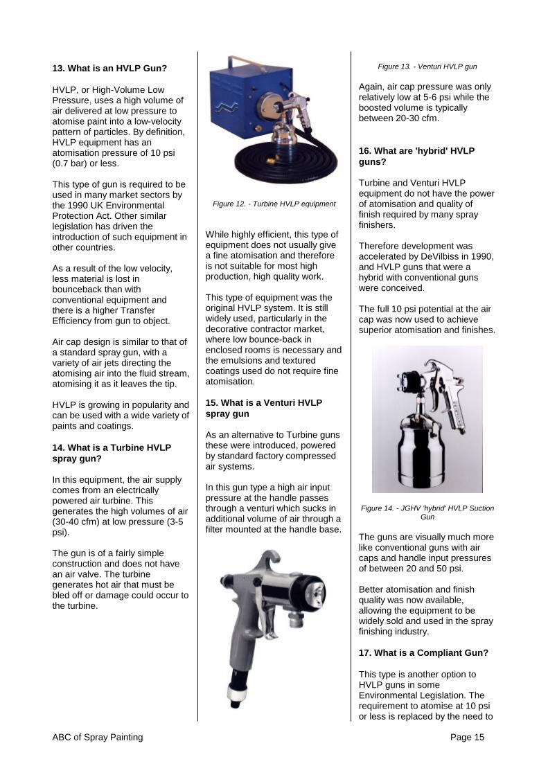
14. What is a Turbine HVLPspray gun?
In this equipment, the air supplycomes from an electricallypowered air turbine. Thisgenerates the high volumes of air(30-40 cfm) at low pressure (3-5psi).
The gun is of a fairly simpleconstruction and does not havean air valve. The turbinegenerates hot air that must bebled off or damage could occur tothe turbine.
Figure 12. - Turbine HVLP equipment
While highly efficient, this type ofequipment does not usually givea fine atomisation and thereforeis not suitable for most highproduction, high quality work.
This type of equipment was theoriginal HVLP system. It is stillwidely used, particularly in thedecorative contractor market,where low bounce-back inenclosed rooms is necessary andthe emulsions and texturedcoatings used do not require fineatomisation.
15. What is a Venturi HVLPspray gun
As an alternative to Turbine gunsthese were introduced, poweredby standard factory compressedair systems.
In this gun type a high air inputpressure at the handle passesthrough a venturi which sucks inadditional volume of air through afilter mounted at the handle base.
Figure 13. - Venturi HVLP gun
Again, air cap pressure was onlyrelatively low at 5-6 psi while theboosted volume is typicallybetween 20-30 cfm.
16. What are 'hybrid' HVLPguns?
Turbine and Venturi HVLPequipment do not have the powerof atomisation and quality offinish required by many sprayfinishers.
Therefore development wasaccelerated by DeVilbiss in 1990,and HVLP guns that were ahybrid with conventional gunswere conceived.
The full 10 psi potential at the aircap was now used to achievesuperior atomisation and finishes.
Figure 14. - JGHV 'hybrid' HVLP SuctionGun
The guns are visually much morelike conventional guns with aircaps and handle input pressuresof between 20 and 50 psi.
Better atomisation and finishquality was now available,allowing the equipment to bewidely sold and used in the sprayfinishing industry.
17. What is a Compliant Gun?
This type is another option toHVLP guns in someEnvironmental Legislation. Therequirement to atomise at 10 psior less is replaced by the need to

Page 16 ABC of Spray Painting
have a minimum of 65% TransferEfficiency. It is felt that this giveseven better atomisation potentialwhile still reducing emissions andmaterial use.
Figure 15. - GTI Compliant guns
This type of gun is the current topof the range gun available fromDeVilbiss.
18. How do I recognise aSuction feed Compliant orHVLP gun?
On DeVilbiss UK guns the suctionfluid tip has an external profilesimilar to that of a conventionalgun. However in additiona) the part number stamped onthe outer rim of the tip will startwith the code letters JGHV or GTIandb) when the appropriate air cap isin place the tip will protrude infront of the cap.
Figure 16. - Suction HVLP and Compliantfluid tip
Figure 17. - Suction HVLP and Compliantset-up
19. How do I recognise aPressure feed Compliant orHVLP gun?
On DeVilbiss UK guns thepressure fluid tip has a unique‘ski-ramp’ profile unlike any othertip style. In additiona) the part number stamped onthe outer rim of the tip will startwith the code letters JGHV or GTIandb) when the appropriate air cap isin place the tip will protrude infront of the cap.
Figure 18. - Pressure HVLP andCompliant fluid tip
Figure 19. - Pressure HVLP andCompliant set-up
Sprayers Tip:Don’t forget that a suction air cap,fluid tip and needle can be usedon a pressure feed fluid systemas well as a suction/gravity one.However a pressure set-upcannot be used visa versa.
20. What is an Automatic Spraygun?
This gun is designed for use onautomatic machinery and roboticspraying installations.
It has no handle or externaltrigger because it needs to becontrolled by remote operationvia control panels and/or solenoidvalves.
The fluid tips and air caps areexactly the same items as usedon manual guns and, if set upcorrectly, will give exactly thesame performance.
Automatic guns are available inConventional, HVLP andCompliant types.
Figure 20. - Automatic Spray gun
PART IDENTIFICATION &FUNCTION
21. What are the principal partsof a spray gun?
Figure 21. - Spray Gun Anatomy

ABC of Spray Painting Page 17
22. What happens when thetrigger is pulled?
The trigger operates in twostages - Initial trigger movementopens the air valve, allowing air toflow through the gun.
Further movement of the triggerpulls the fluid needle from its seatat the fluid tip, allowing fluidmaterial to flow. When the triggeris released, the fluid flow stopsbefore the airflow.
This lead/lag time in the triggeroperation assures atomisation airwhen the fluid flow starts. It alsoassures atomisation until the fluidflow stops, so there is no spittingof unatomised fluid.
23. What is the function of theair cap?
The air cap (see figure 23) directscompressed air into the fluidstream to atomise it and form thespray pattern. (see Figure 27)
Figure 22. - Types of Spray Patterns
There are various styles of capsto produce different sizes andshapes of patterns for manyapplications.
24. What are the advantages ofthe external mix air cap?
This cap design provides betteratomisation of more viscousmaterials and is the standard typeof cap used on air atomisationguns.It allows higher atomisationpressures to be used on moreviscous materials and providesgreater uniformity and control ofpattern shape.
It also provides better atomisationfor materials that can be sprayedwith lower pressures.
Figure 23. - External Mix Air Cap
25. How should an air cap beselected?
The following factors must beconsidered:
a) volume and pressure of airavailable at the handle of the gun.b) material feed system used(pressure, suction or gravity)c) material type, viscosity andvolume of material to be sprayedd) shape of pattern required (seefigure 22)e) size of fluid tip to be used(most air caps work best withcertain fluid tip/needlecombinations)f) size and nature of object, orsurface to be sprayed.
Remember - multiple, or larger,orifices increase the ability toatomise more material for fasterpainting of large objects but alsoincrease the air consumption ofthe air cap.
See the DeVilbiss spray gunliterature for information on capair consumption and suggestedapplications.
26. What is the function of thefluid tip and needle?
They restrict and direct the flow ofmaterial from the gun into the airstream. The fluid tip includes aninternal seat for the tapered fluidneedle, which reduces the flow ofmaterial as it closes. (see Figure26).
The amount of material thatleaves the front of the gundepends upon the viscosity of thematerial, the material fluidpressure and the size of the fluidtip opening provided when theneedle is unseated from the tip.
Fluid tips are available in a varietyof sizes to properly handlematerials of various types, flowrates and viscosity.
Figure 24. - The Fluid Tip and Needle
27. What is the air cap & tipcombination?
In practice, the air cap, fluid tipand needle are selected as a set,since they all work together toproduce the quality of the spraypattern and finish. These threeitems, as a unit, are referred to asthe nozzle combination, the gunset-up or air cap and tipcombination.
Figure 25. - Cap tip & needle set-up
28. Why do some fluid needleshave different end profiles?
This is for two reasonsa) as the hole in the fluid tipbecomes smaller the needle endprofile has to still sit on and sealagainst the tip internal profile sothe end angle also becomes less,andb) fluid needles that are normallymatched with tips used forpressure feed applications have ashort parallel section on their endto push out and paint residuefrom the tip internal profile whenthe gun trigger is released. Forthis reason they are called‘Cleaner-tip’ profiles.

Page 18 ABC of Spray Painting
Figure 26. - Different Fluid NeedleProfiles
29. What are typical fluid tipsizes and flow rates?
The typical sizes, correspondingfluid tip opening dimensions andflow rates are shown below in thetables. Note that only a small partof the tip range available isshown.
DeVilbissFluid Tip
Size Code
OrificeSize
TypicalFlowRate
Pressure Feed SystemG 0.7 mm < 100
cc/minFX 1.1 mm < 200
cc/minFZ 1.2 mm < 300
cc/minFF 1.4 mm < 400
cc/minFW 1.6 mm < 500
cc/minEX 1.8 mm < 600
cc/minSuction Feed System
FF 1.4 mm < 200cc/min
FW 1.6 mm < 250cc/min
EX 1.8 mm < 300cc/min
Gravity Feed SystemFF 1.4 mm < 250
cc/minFW 1.6 mm < 300
cc/minEX 1.8 mm < 350
cc/min
Figure 27. Typical Fluid Flows
Sprayers TipHVLP and Compliant type Suctionand Gravity guns generallygenerate less venturi effect thantheir conventional counterpartsand therefore give lower fluid flowrates. Therefore it is usual toincrease the fluid tip size by oneor two sizes. However, rememberthat HVLP and Compliant gunshave a greater transfer Efficiencythan conventional guns andtherefore a slightly lower fluid flowis not necessarily a problem.
30. How are fluid tip and needlesizes identified?
DeVilbiss fluid tips and needleshave traditionally been identifiedby code letters stamped on the tipand the needle. This is still truefor the conventional JGA/GFGguns and the JGHV/GFHVseries. In addition the size inmillimetres and 1000’s of an inchis marked. However on all newguns introduced since 1998 wehave dropped the code letterdesignation in favour of the holesize – it makes it easier toidentify.
Different ranges of tips areavailable for different gun types,check the appropriate literaturefor the exact range available foryour gun.
31. What fluid tip and needlecombination sizes are mostcommon?
E, EX, FW, FF and FX are themost commonly used tip &needle combinations.
The EX 1.8mm and FW 1.6mmcombinations are used for suctionfeed.
The EX 1.8mm and FF 1.4mmare used for gravity Feed.
For pressure feed the mostcommon tips are FX 1.1mm, FF1.4mm and E 1.8mm.
32. How are air cap, fluid tipand needle combinationsselected?
Five basic considerations are in-
volved in selecting the cap, tipand needle combination:
(1) The type and model of thegun (different guns = differentrange available(2) Available air supply(3) The type and viscosity of thematerial being sprayed.(4) The physical size of the objectto be painted. As a general rule,use the largest possible spraypattern consistent with the objectsize. Remember that different aircaps deliver various patterncharacteristics. This can reduceboth spraying time and thenumber of gun passes.(5) The speed with which thefinish will be applied and thedesired level of quality.
For speed and coverage, choosea combination which produces apattern as wide as possible.
When quality is the decidingfactor, choose a combinationwhich produces fine atomisationand a smaller pattern size,thereby giving greater applicationcontrol.
For a suction feed gun, there areseveral nozzle types availablewhich are suitable for finishingoperations. These nozzles havefluid tip openings ranging from1.6mm (0.062”) to 1.8mm(0.070”), and are designed tohandle viscosities up to 30seconds in a Din 4 Viscosity Cup
For a pressure feed gun, theamount of material dischargeddepends upon material viscosity,inside diameter of the fluid tip,length and size of hose, andparticularly the pressure on thematerial container or pump.If the fluid tip opening is toosmall, the material streamvelocity will be too high. If thefluid tip opening is too large, youwill lose control over the materialdischarging from the gun.
Pressure feed air caps consumebetween 7.0 and 25.0 CFM,depending on design. If your airsupply is limited, because of anundersize compressor, or manyother air tools are in use at once,

ABC of Spray Painting Page 19
the gun will be starved for air,producing incomplete atomisationand a poor finish.
Rule of thumbThe lower the viscosity of thematerial, the smaller the l.D. of thefluid tip.
NOTE: Viscosity conversioncharts are available to convertone viscosity cup reading toanother from many material orequipment suppliers.
33. What are the criteria forselecting a pressure feed fluidtip?
The fluid discharge in cc/minfrom a suction feed gun isrelatively stable (largely becauseit is determined by atmosphericpressure and it utilises only ashort fluid column). However thefluid discharge from a pressurefeed gun is affected by far morevariables. These include the sizeof the inside diameter of the fluidtip and the pressure on the paintcontainer or pump. The larger theopening, the more fluid isdischarged at a given pressure.
If the fluid tip ID is too small forthe amount of material flowingfrom the gun, the dischargevelocity will be too high. The air,coming from the air cap, will notbe able to atomise it properlycausing a centre-heavy or poorlyatomised pattern.
If the fluid tip opening is too large,material discharge control will belost.
The fluid tip/air cap combinationmust be matched to each otherand to the job at hand. Spray guncatalogues and service literatureinclude charts to help you matchthem properly.
34. Of what metals are fluidtips made?
Traditionally fluid tips have beenmade of several different metalsincluding Mild Steel, Low andHigh Grade Stainless Steel,Nitralloy and Tungsten Carbide.However, over several years we
have standardised on three metaltypes:
High Grade 303 Stainless Steelused for Foods, Pharmaceuticaland all solvent based andwaterbased material types
Hardened Nitralloy for abrasive,but not corrosive, applications
Tungsten Carbide for extremelyabrasive, non corrosive, materialsand coatings.
In addition a small range of tipscontaining a plastic insert havebeen introduced. These havebetter needle/tip sealingcharacteristics for use in someapplications and will eliminate theneed for Lapped Tip and Needlesets.
35. What is the spreaderadjustment valve?
Also known as the fan or Horn aircontrol valve. A valve forcontrolling the air to the hornholes which regulates the spraypattern from maximum widthdown to a narrow or roundpattern (see figure 28).
Figure 28.- Spreader adjustment valve
36. What is the fluid needleadjustment?
This controls the distance thefluid needle is allowed to retractfrom its seat in the fluid tip, whichallows more or less materialthrough the fluid tip (see figure29).
With pressure feed systems, thefluid delivery rate should beadjusted by varying the fluidpressure at the pressure pot. Usethe fluid adjustment knob for
minor and/or temporary flowcontrol. This will extend the life ofthe fluid needle and tip.
Figure 29.- Fluid Adjustment Screw
37. What is an Air Flow ControlValve?
Also known as a Cheater valve,this controls the quantity of airflowing through the gun. This willeffect atomisation and bounce-back. The valve can either befitted into the gun body orattached to the gun handle airinlet.
Figure 30.- Cheater Valves
38. What is the "Ball and Cone"principle?
A feature (Fig. 31) which assuresperfect alignment between the aircap and fluid tip. A precisionmachined conical surface on thetip provides a seat for theprecision machined ball segmentof the cap.
Figure 31.- Ball and Cone Seating

Page 20 ABC of Spray Painting
39. What is a Removable Sprayhead and what are itsadvantages?
A feature on the old DeVilbissMBC spray gun which allowed thespray head (an assemblyconsisting of the air cap, fluid tip,fluid needle and spray head body)to be quickly removed as a unitfrom the spray gun body.
Its advantages were:a) Ability to change spray headand combination to specialisedassemblies for certain materialse.g. sound deadener, veiling etcb) Ease of cleaning.c) In case of damage to the sprayhead, a new gun body is notrequired.d) An extra spray head can besubstituted for one being repairedor cleaned.
The MBC gun is now no longer acurrent gun in the DeVilbissrange, but some othermanufacturers guns, designed forpainters and decorators, still havesimilar features.
Figure 32.- Removable Spray head
40. What are the componentsof suction and gravity feedsystems?
Typical suction and gravity feedsystems consist of: a suction feedor gravity feed spray gun withcup, an air compressor (notshown), a combination filter/airregulator and air hoses (seefigure 33).
Figure 33.- Suction Feed and GravityFeed System Components
OPERATION
41. How is suction and gravityfeed equipment hooked up foroperation?
a) Connect the air supply fromthe compressor outlet to thefilter/air regulator inlet.
b) Connect the air supply hosefrom the air regulator outlet to theair inlet on the spray gun.
c) After the material has been re-duced to proper consistency,thoroughly mixed and strainedinto the cup, attach the gun to thecup (suction feed) or pourmaterial into attached cup (gravityfeed).
42. How are suction andgravity feed systems initiallyadjusted and balanced forspraying?
a) For maximum pattern sizeopen wide the spreader adjustingvalve on the gun. Turn counter-clockwise until it stops.
b) For maximum fluid deliveryback out the fluid adjusting screwto a wide-open position. (Wide-open position is reached whenthe first thread of the screw is
visible).
c) Open the air outlet valve on theair regulator and adjust theatomisation air to approximately30 psi at the gun handle.
d) Spray a static vertical spraypattern to check size and shapeof fan. Any deformation problemsneed to be corrected beforecontinuing (see Troubleshootingsection).
Figure 34.- Vertical Test Pattern
e) Make a few test passes withthe gun on some clean paper. Ifthere is major variation in particlesizes - some specks and/or largeglobs - the paint is not atomisingproperly (see figure 35). Increasethe air pressure slightly and makeanother test pass. Continue thissequence until the paint particlesize is relatively uniform.
Figure 35.- Quick pass sprayout
f) Spray a horizontal test pattern,holding the trigger open until thepaint begins to run. There shouldbe even distribution of paintacross the full width of the pattern(see figure 36). If there is not,there is a problem with either theair cap or the fluid tip which must

ABC of Spray Painting Page 21
be corrected. Refer to theTroubleshooting section forexamples of faulty patterns tohelp diagnose your problem.
Figure 36. - Horizontal Test Runout
g) If the pattern produced by theabove test appears normal, beginspraying.
h) If the pattern seems starvedfor material, and the fluidadjustment screw allows fullneedle travel, the fluid tip may betoo small or the material may betoo heavy. Recheck the viscosityor increase the size of the fluid tipand needle.
i) If the material is spraying tooheavily and sagging, reduce thematerial flow by turning in thefluid adjusting screw (clockwise)or reducing the fluid tip size.
j) If using HVLP, using an “AirCap Test kit’, verify that the aircap pressure is not above 10 psi.
Remember, proper set-up utilisesno more fluid and air pressurethan is needed to produce therequired quality and a flow ratethat will meet productionrequirements.
43. What are the componentsof a pressure feed system?
A pressure feed system consistsof: a pressure feed spray gun, apressure feed tank, cup or pump,an air filter/regulator, appropriateair and fluid hoses, and an aircompressor (see figure 37).
Figure 37.- Pressure Feed SystemComponents
44. How is equipment hookedup for pressure feed spraying?
Connect the air hose from the airregulator to the air inlet on thegun.
Connect the mainline air hose tothe air inlet on the tank.CAUTION: Do not exceed thecontainer’s maximum workingpressure.
Connect the fluid hose from thefluid outlet on the tank to the fluidinlet on the gun.
45. How is the pressure feedgun adjusted for spraying?
Open spreader adjustment valvefor maximum pattern size (seefigure 28).
Open fluid adjustment screw untilthe first thread is visible (seefigure 29).
46. How is the pressure feedgun balanced for spraying?
a) Check that the preliminary gunadjustments described above in45 have been performed: thespreader adjustment controlshould be backed out to the wide-open position and the first threadshould be visible on the fluidadjusting control.
b) Shut off the atomisation air tothe gun. Set the fluid flow rate byadjusting the air pressure in thepaint container. Use about 6 psi
for a remote cup and about 15 psifor a 2-gallon or larger containeras a start pressure.
c) Remove the air cap, aim thegun into a clean container andpull the trigger for 10 seconds.Measure the amount of materialwhich flowed in that time andmultiply by six (or 30 secondsand multiply by two). This is thefluid flow rate in cc per minute.For normal spraying operations itshould be between 250 to 300 ccper minute. If the flow rate is lessthan this, increase the airpressure in the container andrepeat. If it is faster than this,decrease the pressure slightly.When the flow rate is correct,reinstall the air cap.
d) Turn the atomisation air onand adjust to about 40 psi at thegun handle. Spray a static verticalspray pattern to check size andshape of fan. Any deformationproblems need to be correctedbefore continuing (seeTroubleshooting section).
e) Make a few passes on a pieceof paper or cardboard. From thattest pattern, determine if theparticle size is small enough andrelatively uniform throughout thepattern to achieve the requiredfinish quality (see figure 35). Ifparticle size is too large or isgiving too much texture in thefinish, turn the atomisationpressure up in 5 psi incrementsuntil particle size and texture offinish is acceptable.
f) Spray a horizontal test patternholding the trigger open until thematerial begins to run. Paintdistribution across the full width ofthe pattern should be the same.If it is not, there is a problem witheither the air cap or fluid tip whichmust be corrected. Refer to theTroubleshooting section.
g) If the horizontal patternappears normal, the pressurefeed system is ready to spray.

Page 22 ABC of Spray Painting
Figure 38.- Air regulator adjustment
h) Spray a component with thesesettings. If you are not able tokeep up with the production raterequired or if the finish is starvedfor material, increase the fluidpressure with the fluid regulatorcontrol knob in 2 to 4 psiincrements until required wetcoverage is accomplished. Note:A larger capacity fluid tip may berequired.
i) Remember, as you turn up thefluid pressure the particle size willincrease. Once the coveragerequired is obtained, it may benecessary to re-adjust theatomisation pressure in 3 to 5 psiincrements to insure requiredparticle size and finish texture isachieved.
j) If using HVLP, using an “AirCap Test kit’, verify that the aircap pressure is not above 10 psi.
Figure 39.- Air Cap Test Kit
After establishing the operatingpressures required for productionand finish quality, develop aProcess Control program for yourfinish process to follow.
47. What is a Process ControlProgram?
After establishing air and fluidpressures that meet requiredquality and production, record thedata to be used for thatapplication for future reference.(see figure 40)
Process Control RecordNo. 12
Finishing Process: TopcoatBooth: AMaterial Sprayed: Blue 2-pack
PolyurethaneMix Ratio: 2:1:1Spray Viscosity: 22 sec Din4Booth Temperature:23oCBooth R.H: 70%Spray Gun: DeVilbiss JGAAir Cap: 765Fluid Tip: FF 1.4mmFluid Needle: FF 1.4mmAir Pressure: 55psi at handleFluid Flow: 320 cc/minTank pressure: 42 psiNotes: Check viscosity
everybreaktime
Figure 40.- Typical Process ControlRecord
48. How should the spray gunbe held?
It should be held so the pattern isperpendicular to the surface at alltimes.Keep the gun tip 8-10 inches(conventional spray guns) or 6-8inches (HVLP guns) from thesurface being sprayed. A simpleway of determining the correctdistance is shown in figure 41.
Figure 41.- Gun to Target distance
49. What is the propertechnique for spray gun strokeand triggering?
The stroke is made with a freearm motion, keeping the gun at aright angle to the surface at allpoints of the stroke.
Triggering should begin justbefore the edge of the surface tobe sprayed. The trigger should beheld fully depressed, and the gunmoved in one continuous motion,until the other edge of the objectis reached. The trigger is thenreleased, shutting off the fluidflow, but the motion is continuedfor a few inches until it isreversed for the return stroke.
When the edge of the sprayedobject is reached on the returnstroke, the trigger is again fullydepressed and the motioncontinued across the object.
Lap each stroke at least 50%over the preceding one. Lessthan 50% overlap will result instreaks on the finished surface.Move the gun at a constantspeed while the trigger is pulled,since the material flows at aconstant rate.
Another technique of triggering isreferred to as “feathering.”Feathering allows the operator tolimit fluid flow by applying onlypartial trigger travel.
50. What happens when thegun is arced?
Arcing the stroke results inuneven application and excessiveover-spray at each end of thestroke. When the tip is arced atan angle of 45 degrees from thesurface (see figure 42), up to65% of the sprayed material canbe lost.

ABC of Spray Painting Page 23
Figure 42.- Spray Techniques
51. What is the proper sprayingsequence and technique forfinishing applications?
Difficult areas, such as cornersand edges, should normally besprayed first. Aim directly at thearea so that half of the spraycovers each side of the edge orcorner.
Hold the gun an inch or twocloser than normal, or screw thespreader adjustment control in afew turns. Needle travel shouldbe only partial by utilising the“feathering” technique. Eithertechnique will reduce the patternsize.
If the gun is just held closer, thestroke will have to be faster tocompensate for a normal amountof material being applied tosmaller areas.
When spraying a curved surface,keep the gun at a right angle tothat surface at all times. Followthe curve. While not alwaysphysically possible, this is theideal technique to produce abetter, more uniform, finish.
After the edges, flanges and cor-ners have been sprayed, the flat,or nearly flat, surfaces should besprayed.
Remember to overlap the previ-ously sprayed areas by at least50% to avoid streaking.
When painting very narrow sur-faces, you can switch to a smallergun, or cap with a smaller spraypattern, to avoid readjusting thefull size gun. The smaller gunsare usually easier to handle inrestricted areas.
A full size gun could be used,however, by reducing the air
pressure and fluid delivery andtriggering properly.
MAINTENANCE
52. What causes fluid leakagefrom the fluid needle packingnut?
A loose packing nut, worn or dryfluid needle packing. Lubricatepacking with a few drops of lightoil. Tighten packing nut toprevent leakage but not so tightas to grip the fluid needle. Itbecomes necessary to replacethe packing when it is worn.Tighten the packing nut until itgrabs and holds the needle, thenback off the packing nut until theneedle is free to travel into thefluid tip.
53. What causes air leakagefrom the front of the gun? (SeeFig. 43)
a) Foreign matter on valve orseat.b) Worn or damaged valve orseat.c) Broken air valve spring.d) Sticking valve stem due to lackof lubrication.e) Bent valve stem.f) Packing nut too tight.g) Gasket damaged or omitted.
Figure 43.- Air valve
54. How should the air cap becleaned?
Remove the air cap from the gunand immerse it in clean solvent. Ifnecessary, use a bristle brush toclean dried paint. Blow it dry withcompressed air.
If the small holes becomeclogged, soak the cap in cleansolvent. If reaming the holes isnecessary, use a toothpick, abroom straw, or some other softimplement (see figure 44).
Cleaning holes with a wire, a nailor a similar hard object couldpermanently damage the cap byenlarging the jets, resulting in adefective spray pattern.
Figure 44.- Cleaning the Air Cap
55. How should a suction gunbe cleaned?
Turn off the air to the gun, loosenthe cup lid and remove the fluidtube from the paint. Holding thetube over the cup, pull the triggerto allow the paint to drain backinto the cup.
Empty the cup and wash it withclean solvent and a clean cloth.Partially fill it with clean solventand spray it through the gun toflush out the fluid passages bydirecting stream into the back ofthe booth or a gun cleaner. Spraythe minimum amount of solventnecessary to keep VOCemissions to a minimum.
In the UK and some othercountries an enclosed guncleaning machine must be usedto comply with EnvironmentalLegislation.
56. What is an enclosed guncleaner?
Also known as a gun cleaningcabinet, these are machines thatare used to wash and cleansuction and gravity guns. Theyhave been introduced to helpprevent solvents being sprayedand evaporating to atmosphereduring cleaning.
A gun cleaner is an enclosedbox-like structure (vented) withan array of cleaning nozzlesinside.

Page 24 ABC of Spray Painting
Figure 45.- Gun in solvent washingmachine
Guns and cups are placed overthe nozzles, the lid is closed, avalve is depressed, and thepneumatically powered pumpsprays solvent through thenozzles to clean the equipmentfor a pre-set period of time. Theclosed lid keeps solventevaporation to a minimum.
The solvent in the unit isrecycled, and must be replacedperiodically with fresh liquid.
After washing the guns should beremoved, attached to an airlineand any residual liquid in the airand fluid passageways blown out.Then wipe the gun exterior overwith a clean cloth. It is alsorecommended that the gun belubricated after cleaning (seeFigure 47)
57. How should a pressure gunbe cleaned?
To clean a pressure feed gunwith remote cup or tank, turn offair supply to the cup or tank.Release material pressure fromthe system by opening reliefvalve.
Material in hoses may be blownback. The lid must be loose andfluid pressure off. Keep gunhigher than container, loosen aircap two or three turns and triggergun until atomising air forcesmost of the material back into thepressure vessel.
Clean the container and addsolvent. Pressurise the systemand run solvent until clean.(Note: atomisation air should beturned off during this procedure.)
Dry hose by again loosening the
cap and container lid and forcingair back through the gun andhose. Clean air cap and fluid tip.Clean out tank and reassemblefor future use.
Wipe off the gun with a solvent-soaked rag, or if necessary,brush the air cap and gun with afibre brush using clean-up liquidor thinner.
58. What is a hose cleaner?
A device which incorporates afluid mixer valve which forces afinely atomised mixture of solventand compressed air through fluidhose and paint passages, riddingthem of paint residue. A manualvalve stops the flow of solventand allows air to dry theequipment being cleaned. (SeeFig. 46).
The cleaner can speed upequipment and hose cleaning andvery efficiently purge all materialfrom the internal surfaces. Caremust be taken that both the hosecleaner and gun are properlygrounded due to potential staticcharges being formed
Figure 46.- Using a Hose Cleaner
59. What parts of the gunrequire lubrication? (Figure 47)
The fluid needle packing (A), theair valve packing (B) and thetrigger bearing screw (C) requireregular lubrication with a non-
silicone/non-petroleum gunlubrication oil.
The fluid needle spring (D)should be coated lightly withpetroleum jelly or a non-siliconegrease.
Lubricate each of these pointsafter every cleaning in a gunwasher!
Figure 47.- Lubrication Points

ABC of Spray Painting Page 25
TROUBLESHOOTING
Problem Cause Correction
1. Packing nut loose 1. Tighten, do not bind needleFluid leaking from packingnut 2. Packing worn or dry 2. Replace or lubricate
1. Sticking air valve stem 1. LubricateAir leaking from front ofgun 2. Foreign matter on air valve or
seat2. Clean
3. Worn or damaged air valve orseat
Replace
4. Broken air valve spring 4. Replace5. Bent valve stem 5. Replace6. Air valve gasket missing
damaged or missing6. Replace
1. Dry packing 1. Lubricate2. Packing nut too tight 2. Adjust
Fluid leaking or drippingfrom front of pressure feedgun 3. Fluid tip or needle worn or
damaged3. Replace tip and needle with
lapped set4. Foreign matter in tip 4. Clean5. Fluid needle spring broken 5. Replace6. Wrong size needle or tip 6. Replace
All Feed SystemsJerky, fluttering spray 1. Loose or damaged fluid
tip/seat1. Tighten or replace
2. Dry packing or loose fluidneedle packing nut
2. Lubricate packing or tightenpacking nut
3. Material level too low 3. Refill4. Container tipped too far 4. Hold more upright5. Obstruction in fluid passage 5. Backflush with solvent6. Loose or broken fluid tube or
fluid inlet nipple6. Tighten or replace
Suction Feed Only7. Material too heavy 7. Thin or reduce8. Air vent clogged 8. Clear vent passage9. Loose, damaged or dirty lid 9. Tighten, replace or clean
coupling nut10. Fluid tube resting on cup
bottom10. Tighten or shorten
11. Damaged gasket behind fluidtip
11. Replace gasket

Page 26 ABC of Spray Painting
Problem Cause Correction
Top or bottom-heavy spraypattern
1. Horn holes plugged 1. Clean, ream with non-metallic point (i.e. toothpick)
2. Obstruction on top or bottom offluid tip
2. Clean
3. Cap and/or tip seat dirty 3. Clean
Right or left-heavy spraypattern
1. Horn holes plugged 1. Clean, ream with non-metallic point (i.e. toothpick)
2. Dirt on left or right side of fluidlip
2. Clean
*Remedies for the top, bottom, right, left heavypatterns are:1. Determine if the obstruction is on the air cap or fluidtip. Do this by making a static test spray pattern. Then,rotate the cap one-half turn and spray another pattern.If the defect is inverted, obstruction is on the air cap.Clean the air cap as previously instructed.2. If the defect is not inverted, it is on the fluid tip.Check for damage or contamination on the edge of thefluid tip. Remove contamination or replace tip asnecessary.3. Check for dried paint just inside the opening.Remove paint by washing with solvent.
Centre-heavy spray pattern 1. Fluid pressure too high foratomisation air (pressure feed)
1. Balance air and fluidpressure. Increase patternwidth
2. Material flow exceeds air cap’scapacity
2. Thin or reduce fluid flow
3. Spreader adjustment valve settoo low
3. Adjust
4. Atomising pressure too low 4. Increase pressure5. Material too thick 5. Thin to proper consistency
Split spray pattern 1. Fluid adjusting knob turned intoo far
1. Back out counter-clockwiseto increase flow
2. Atomisation air pressure toohigh
2. Reduce at regulator
3. Fluid pressure too low(pressure feed)
3. Increase fluid pressure
4. Fluid tip too small 4. Change to larger tip

ABC of Spray Painting Page 27
Problem Cause Correction
Starved spray pattern 1. Inadequate material flow 1. Back fluid adjusting screwout to first thread orincrease fluid pressure
2. Low atomisation air pressure(suction feed)
2. Increase air pressure andrebalance gun
Unable to form roundspray pattern
1. Fan adjustment stem notseating properly
1. Clean or replace
Dry spray 1. Air pressure too high 1. Lower air pressure2. Material not properly reduced
(suction feed)2. Reduce to proper
consistency andtemperature
3. Gun too far from surface 3. Adjust to proper distance4. Gun motion too fast 4. Slow down
Excessive overspray 1. Too much atomisation airpressure
1. Reduce pressure
2. Gun too far from surface 2. Use proper gun distance3. Improper technique (arcing,
gun speed too fast)3. Use moderate pace,
keeping gun parallel to worksurface
Excessive fog 1. Too much, or too fast dryingthinner
1. Remix with proper reducerand temperature
2. Too much atomisation airpressure
2. Reduce pressure
Will not spray 1. Pressure feed cap/tip usedwith suction feed
1. Use suction feed cap/tip
2. No air pressure at gun 2. Check air lines3. Fluid needle not retracting 3. Open fluid adjusting screw4. Fluid too heavy (suction feed) 4. Lower fluid viscosity or
change to pressure feed

Page 28 ABC of Spray Painting
12. Fluid Feed
INTRODUCTION
All spray Systems - from thesmallest airbrush to the mostsophisticated finishing system -must have containers to hold thematerial being applied and/or amethod of feeding the material tothe front of the gun.
Material container types andsizes vary considerably,depending on the kind of sprayingsystem being used. Likewise themethods of feeding the liquid tothe spray head can vary –diaphragm pumps, piston pumpsor the more simple pressure feedtanks.
This chapter will discuss thesemethods, their particular applica-tions, their construction, workingand maintenance.
VISCOSITY
1. What is viscosity?
The viscosity of a liquid is its bodyor thickness, and it is a measureof its internal resistance to flow.Viscosity varies with the type andtemperature of the liquid. Anyreference to a specific viscositymeasurement must beaccompanied by a correspondingtemperature specification.
The most common measurementused to determine viscosity infinishing is flow rate (measured inseconds from a Ford, Din, BS orother viscosity cup).
Figure 1.- Viscosity cup
Different viscosity cup sizes areavailable. Each cup has a hole at
the bottom, specified to an exactsize. Use a viscosity cup that isdesigned to handle the timerange of the materials in use.Viscosity control is an extremelyimportant and effective method tomaintain application efficiencyand quality consistency. Alwaysmeasure viscosity after eachbatch of material is mixed andmake sure material temperatureis the same, normally a nominal20oC (70 F).
Viscosity recommendations mayalso be given in poise andcentipoise (1 poise=100centipoise).
Viscosity conversion may beaccomplished by consulting anappropriate viscosity conversionchart.
This type of measurement onlyworks for Newtonian fluids i.e.fluids that have constant shearcharacteristics.
2. What other methods arethere for measuring a liquidsflow characteristics
Non-Newtonian fluids (such asmany thixotropic waterbasedpaints) have to be measured in adifferent method.
When using a Rotometer ashaped paddle is rotated in asample of the material. Thetorque or force needed to rotatethe paddle is measured and usedas a figure to compare it withother materials.
Figure 2.- Rotometer
When measuring the flowcharacteristics of Ceramic Glazea slump meter can be used. Anopen-ended tube is placedupright on the centre of ahorizontal target of concentricrings. The tube is filled with glazeand then lifted, allowing thematerial to flow over the target.The number of rings that theglaze covers is counted and usedas a comparison with othermaterials.
These are only two of many othermethods of measuring amaterials characteristics.
CUPS
3. What different methods areused to feed fluid to the gun?
There are five main methods:
1) Suction feed2) Gravity feed3) Pressure Cup4) Pressure Tank5) Pump
4. What is a Suction Feed Cupand how does it work?
This is a small - usually 1 Litre orless - vented container attachedto the gun. The vent hole allowsatmospheric pressure to enter thecup. When the gun trigger ispulled and compressed air exitsfrom the air cap of the gun, avacuum is created at the tip end.Since the pressure in thecontainer is now higher than thatat the tip, material is forced upthe delivery tube in the container,through the gun passages andout through the fluid tip, wherethe compressed air atomises it.This type container is commonlyused where a small amount ofrelatively thin material (lowviscosity) is being sprayed.

ABC of Spray Painting Page 29
Figure 3.- Suction Cup
5. What capacities do SuctionFeed Cups have?
Suction feed cups can range fromquite small - about 20 cc forairbrushes - to about 1 Litre for aproduction gun. They are seldomany larger than a 1 Litre.
6. What is a Gravity Feed Cupand how does it work?
This are also a small - usually600 cc or less - vented containerattached to the top of the gun.The vent hole again allowsatmospheric pressure to enter thecup. Gravity pulls the materialdown to the gun head. Inaddition, venturi is also generatedwhich adds to the fluid flow.
This type container is commonlyused where a small amounts ofmaterial is being sprayed. Thecombination of venturi and gravityallows heavier bodied material tobe fed than is possible withsuction feed.
Figure 4.- Gravity Cup
7. What is a Pressure Feed Cupand how does it work?
This type container which eitherattaches to the gun or attachesby short hoses so that theoperator carries it. Is not ventedand therefore does not dependon the development of a vacuum
at the fluid tip to work. Instead,the material in the cup ispressurised by the atomisingcompressed air or via a smallregulator, and this higher-than-atmospheric pressure forces thematerial out of the cup, throughthe gun passages and out thefluid tip, where compressed airatomises it as usual.The pressure feed cup is typicallyused for materials which are toothick (high viscosity) for, or higherflow rates than suction feedequipment can supply.
It is really a small portablepressure feed tank.
8. What capacities do PressureFeed Cups have?
Pressure feed cups normallyhave up to 2 Litre capacities.
Anything larger is considered apressure feed tank and would bepositioned some distance fromthe gun.
9. How are Pressure Feed Cupsclassified?
There are three kinds: non-regulator, regulator and remotetypes. The non-regulator type isnot common in professionalfinishing systems, as it has nofluid pressure controlling deviceand is generally used withrelatively small air compressingsystems.
Figure 5.- Non-regulator Pressure FeedCup
The regulator type cup has a
built-in regulator which controlsthe fluid pressure independentlyof the atomisation air pressure,permitting better control of thecup pressure.
Figure 6.- Regulator Pressure Cup gun
The Remote cup is connected tothe gun by short hoses (approx 1metre) and has a a controlableregulator that can vary theinternal pressure. It also includesother items that are fitted to a fullsize pressure tank such as asafety valve, pressure gauge andpressure release valve.
Figure 7.- KB 2 Remote Pressure Cup
TANKS
10. What are Pressure Feedtanks and how do they work?
Pressure feed tanks are closedcontainers, ranging in size fromabout 9 Litres (2 gall) to 45 Litres(10 gall). They provide a constantflow of material, under constantpressure, to the spray gun.

Page 30 ABC of Spray Painting
The tank is pressurised withclean, regulated, compressed air,which forces the fluid out of thetank through the fluid hose to thegun.
The rate of fluid flow is controlledby increasing or decreasing theair pressure in the tank.
A typical pressure feed tankconsists of: the shell (A), clamp-on lid (B), fluid tube (C), fluidoutlet (D), regulator (E), gauge(F), safety relief valve (G), andagitator (H) (see figure 8).
Pressure feed tanks are normallyavailable with either top or bottomfluid outlets.
Figure 8.- Pressure Feed Tank
11. Where are pressure feedtanks recommended?
Pressure feed tanks provide asimple, practical, economicalmethod of feeding material to thegun over extended periods oftime.
They are mostly used incontinuous production situations,because the material flow ispositive, uniform and constant.
Tanks can be equipped withagitators (see Figure 3) that keepthe material mixed and insuspension
12. When is an agitator used ina pressure feed tank?
When the liquid being used has apigment or material that must bekept in motion to keep itsparticles in proper suspension.An agitator can be hand, air orelectrically driven.
13. What is a single regulatedtank?
This is a pressure feed tank withone air regulator mounted on thelid controlling only the pressureon the material in the tank (seefigure 9). Most tanks used aredesigned this way
Figure 9.- Single Regulated Tanks
Some tanks are fitted with asecond regulator to controlatomisation pressure to the gun.These are normally called Doubleregulator tanks
14. To what standards arepressure tanks manufactured?
Pressure Feed Tanks have beenconstructed in the past to BS1101 and ASME (AmericanSociety of Mechanical Engineers,a US standard).
From November 1999 thePressure Equipment Directive97/23/EC became law in the UK(although not manditary until May2002), which sets therequirements for the design,manufacture, inspection andcertification of PFT's.
Those that comply with the newstandard will bear the 'CE' mark.
This harmonised standard meansthat equipment manufactured tothe requirements of the PED,bearing the 'CE' mark, can besold in any of the member statesof the EU.
15. What materials are used toconstruct pressure feed tanks?
Heavy-duty, ASME-code andBS/PED tanks are made ofgalvanised mild steel plate or 304series electropolished stainlesssteel. They also have zinc platedor stainless steel lids with forgedsteel clamps.
When abrasive or corrosivematerials are being sprayed, theinside of the tank shell cansometimes be coated or linedwith a special material such asTeflon or Vitreous Enamel, or acontainer insert or liner is used.
16. What are container linersand inserts?
Inserts are containers that areplaced inside the tank to hold thematerial, keeping it from directcontact with the tank walls. Theycan be constructed from Tinplateor Stainless Steel.
Tank liners are thin plasticmouldings that fit inside the tankbase and carry out the samefunction. They are made ofdisposable polyethylene.
Figure 10.- Tank liner and insert container
Using liners and inserts reducestank cleaning time and makescolour changeover easier.
17. When would you use abottom outlet tank?
1) When you are using veryviscous materials.

ABC of Spray Painting Page 31
2) When you wish to use all thematerial in the tank and you arenot using an insert.
18. What would I use if I havedifficulty accurately settinglower fluid pressures?
An extra-sensitive regulator maybe available for use with lowerfluid flow and/or lower viscositymaterials where precise control isneeded.
19. How often should apressure tank be tested?
UK Insurance companiesnormally require pressure tanksof 2 gallons (9 Litres) capacity orgreater to be pressure tested andcertified every 18 months.However this duration may differbetween different companies.Check with your own insurer.
PUMPS
20. What is a fluid pump?
This is a mechanical device formoving fluid under pressure fromits storage container or reservoirto the point of use.
There are two main sources ofpower – compressed air andelectricity. Due to the hazardousand inflammable nature of manyof the liquids used in the finishingindustry, compressed air isnormally the favoured powersource. Electric motors(flameproof) are usually onlyused in large paint circulatingsystems in Vehicle manufacturingplants and large industry.
All fluid pumps are designed tooutput a certain volume (cc/min)at a given pressure (psi). Allpumps are rated by these twoparameters.
Because electrically poweredturbine pumps are a specialistsubject, we will examine the morecommonly used pump types.
21. What types of Fluid pumpsare available?
Two main types are available –diaphragm and piston. Both areavailable in different fluid outputand pressure ratings.
Diaphragm pumps can be verticalor horizontal and can be madefrom plastics, aluminium orstainless steel.
Figure 11.- Aluminium Double Diaphragmpumps
Piston pumps are normally madefrom stainless steel, Aluminiumand mild steel.
Figure 12.- Piston pump
Always check that the materialsof construction, ball material andpacking type are compatible withthe material to be pumped.
22. How are fluid pumpsspecified?
Performance of a pump is
normally specified by threeparameters
(1) fluid output in cc per stroke orcc per cycle
(2) Ratio of pump pressure – i.e.1:1, 2:1,10:1 etc. This means thatan air input pressure of 1 psi willresult in a fluid output pressure of1psi or 2 psi or 10 psi etc.
3) the maximum number ofstrokes or cycles per minute thatthe pump can function at withoutseverely accelerating wear of thepump components.
Other information may beavailable but these three facts arethe most important.
23. How does a DoubleDiaphragm pump work?
This type of pump uses twoflexible diaphragms to applypressure to the liquid in twochambers. They are linkedtogether so that as liquid ispushed out of one chamber, fluidis drawn into the other. The pumpfluid passageways incorporateseveral ball valves that ensurethat fluid only flows in onedirection when the diaphragmschange stroke.
Figure 13.- Acetal Double Diaphragmpump
24. When do I use a diaphragmpump?
Diaphragm pumps can be used inmost pumping applications. Therange of pumps available has awide range of fluid outputs from20 cc/cycle up to 3000 cc/cycle.

Page 32 ABC of Spray Painting
Many pumps of this sort are usedas an alternative to pressure feedtanks for small to mediumfinishing operations as well assmall circulating systems.
The wide range of materials thatthe pumps can be constructed ofallows many fluid to be pumpedincluding lubrication oils, solventand waterbased paints.
The squeezing action of adiaphragm pump makes itsuitable for moving certainmaterials that the shearing actionof piston pumps cannot. Theseinclude latex adhesives andceramic glaze.
25. How does a piston Pumpwork?
This pump has two main sections– an upper air motor and a lowerfluid section.
In a similar way to a diaphragmpump, an upper air pistonreciprocates vertically and acts asthe motive force for moving to aconnected lower fluid piston.
Because the air and fluid pistonsare totally divorced it is easy todesign and manufacture pumpswith ratios greater than 1:1. Lowpressure pumps (2:1 up to 10:1)and high pressure pumps (10:1up to 73:1) have the same basicconstruction except for the variedcross sectional area of the twopistons.
The fluid piston and pumpincorporates one way valves toensure the material only moves inone direction.
26. When do I use a Pistonpump?
Due to the range of ratiosavailable, these pumps cansupply fluid at higher pressuresthan diaphragm pumps.Therefore they are primarily usedwhere the material has higherviscosity or needs to be movedover longer distances.
While they have wide use in dead
head systems for high pressureAirless and Air assisted Airlessspraying systems, they areparticularly suitable for use inlarge paint circulation systems.
27. What is a ‘Dead Head’System?
This is any fluid supply systemthan runs from the source (pumpor tank) to the gun with no returnto the source.
It is the most common supplysystem for finishing.
Figure 14.- Dead head Fluid Supplysystem
28. What is a CirculationSystem?
This fluid supply system movesfluid from its source to the gunand then has a return line runningback to the source and itsreservoir.
This system is used in higherproduction plants that utilisematerials that need to be kept inconstant suspension.
Figure 15.- Circulating Fluid SupplySystem
29. What is a Back PressureValve?
In a circulation system there mustbe some way to ensure that,when the gun trigger is pulled,fluid finds it easier to flow out of
the fluid tip and not return to thereservoir. A back pressure valveis a method of adjusting the flowresistance in the return line tomake sure the fluid finds it easierto exit the gun. The valve isadjustable and will automaticallyvary its orifice size in an attemptto maintain the preset fluid linepressure when the gun is fired.
30. What is a PulsationChamber?
The cycling action of thediaphragm or piston produceshigh and low pressure pulses asthe pump works. This is shownby surges in the fluid columnexiting the fluid tip of the gun.This surges can createinconsistencies in the finish beingachieved.
To help overcome these pulses achamber can be fitted to thepump outlet. In its most simpleform the fluid pressure is used tocompress the air trapped in thetop of the chamber. It then actsas a spring during the pulses andhelps smooth out the surges.
31. What is a Fluid regulator?
This carries out the samefunction as an air regulator but itis fitted with components and adiaphragm that resist solventsand liquids.
Figure 16.- Fluid regulator
A fluid regulator will keep the fluidpressure to the gun constantwhile the pump pressurefluctuates (within specifiedparameters)
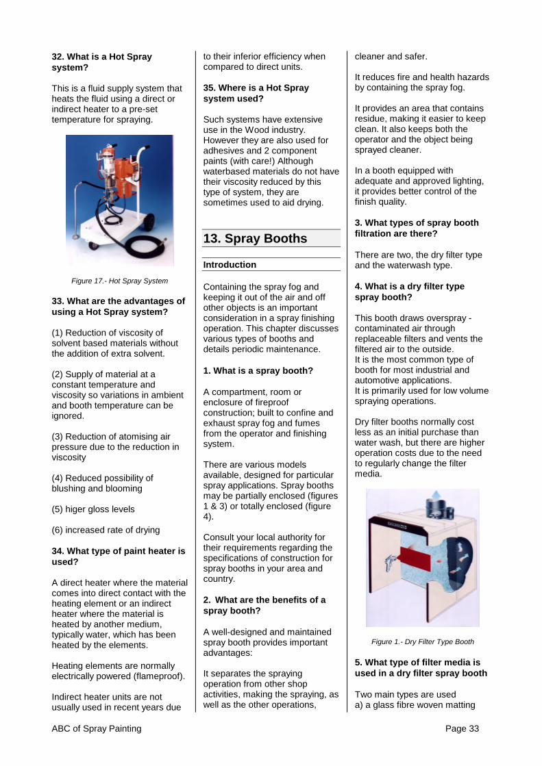
ABC of Spray Painting Page 33
32. What is a Hot Spraysystem?
This is a fluid supply system thatheats the fluid using a direct orindirect heater to a pre-settemperature for spraying.
Figure 17.- Hot Spray System
33. What are the advantages ofusing a Hot Spray system?
(1) Reduction of viscosity ofsolvent based materials withoutthe addition of extra solvent.
(2) Supply of material at aconstant temperature andviscosity so variations in ambientand booth temperature can beignored.
(3) Reduction of atomising airpressure due to the reduction inviscosity
(4) Reduced possibility ofblushing and blooming
(5) higer gloss levels
(6) increased rate of drying
34. What type of paint heater isused?
A direct heater where the materialcomes into direct contact with theheating element or an indirectheater where the material isheated by another medium,typically water, which has beenheated by the elements.
Heating elements are normallyelectrically powered (flameproof).
Indirect heater units are notusually used in recent years due
to their inferior efficiency whencompared to direct units.
35. Where is a Hot Spraysystem used?
Such systems have extensiveuse in the Wood industry.However they are also used foradhesives and 2 componentpaints (with care!) Althoughwaterbased materials do not havetheir viscosity reduced by thistype of system, they aresometimes used to aid drying.
13. Spray Booths
Introduction
Containing the spray fog andkeeping it out of the air and offother objects is an importantconsideration in a spray finishingoperation. This chapter discussesvarious types of booths anddetails periodic maintenance.
1. What is a spray booth?
A compartment, room orenclosure of fireproofconstruction; built to confine andexhaust spray fog and fumesfrom the operator and finishingsystem.
There are various modelsavailable, designed for particularspray applications. Spray boothsmay be partially enclosed (figures1 & 3) or totally enclosed (figure4).
Consult your local authority fortheir requirements regarding thespecifications of construction forspray booths in your area andcountry.
2. What are the benefits of aspray booth?
A well-designed and maintainedspray booth provides importantadvantages:
It separates the sprayingoperation from other shopactivities, making the spraying, aswell as the other operations,
cleaner and safer.
It reduces fire and health hazardsby containing the spray fog.
It provides an area that containsresidue, making it easier to keepclean. It also keeps both theoperator and the object beingsprayed cleaner.
In a booth equipped withadequate and approved lighting,it provides better control of thefinish quality.
3. What types of spray boothfiltration are there?
There are two, the dry filter typeand the waterwash type.
4. What is a dry filter typespray booth?
This booth draws overspray -contaminated air throughreplaceable filters and vents thefiltered air to the outside.It is the most common type ofbooth for most industrial andautomotive applications.It is primarily used for low volumespraying operations.
Dry filter booths normally costless as an initial purchase thanwater wash, but there are higheroperation costs due to the needto regularly change the filtermedia.
Figure 1.- Dry Filter Type Booth
5. What type of filter media isused in a dry filter spray booth
Two main types are useda) a glass fibre woven matting

Page 34 ABC of Spray Painting
b) a cardboard 'concertina'
The glass fibre media normally isbuilt up in layers of wovenmatting that are stripped offduring its working life as the filterbecomes loaded with paintresidue. This has the effect ofincreasing the working life of themedia but gradually reducing itsfiltration efficiency.
The cardboard media isconstructed in such a way thatthe paint laden air stream isforced to change directionseveral times causing it to throwout its contamination. It does nothave the 'absorbency' of theglass fibre matting type but has ahigher working efficiencythroughout its life and is capableof being 'self-supporting' whenmounted in its location frame inthe spray booth.
Figure 2.-Dry Filter Material Types
6. What is a waterwash typebooth?
A waterwash booth actuallywashes the contaminatedoverspray air using a cascade ofwater, trapping the paint solids asthe air-flows through it. Ifmaintained correctly these boothsare extremely efficient in theiroperation.
Waterwash booths are generallyused when spraying highvolumes of paint.
They are more expensive topurchase, but running costs canbe lower due to their ability towork efficiently for long timebetween clean out.
Figure 3.- Waterwash Industrial TypeSpray Booth
Figure 4.- Automotive Downdraft DryFilter Booth
7. What is an axial flow exhaustfan?
A typical axial flow exhaust fanconsists of a motor, a multipleblade fan, pulleys and belts. Itremoves overspray from thespray booth area (see figure 5).
The design of axial flow exhaustfans prevents overspray fromcoming into contact with the drivemechanism and electric motor.
Blades are made of non-sparkingmetal or plastic.
Figure 5.- Axial Flow Exhaust fan
8. What is a Centrifugal Fan?
This type of fan develops higherpressure and is used on largerspray booths that require morepower and/or more air volumethan is capable with axial flowfans.
Sometimes called a 'Snail shell'fan, the air is drawn into thecentre of the fans rotatingimpellor and thrown outcentrifugally through its vanes.
Figure 6.- Centrifugal Fan
9. What is air velocity?
Air velocity in a finishingoperation is the term used todescribe the speed of air movingthrough the spray booth - overand around the sprayer.
10. What effect does airvelocity have on spray boothefficiency?
Air must move through the boothwith sufficient velocity to carryaway overspray.

ABC of Spray Painting Page 35
Too low a velocity causes poor,even potentially dangerousworking conditions, especiallywhen the material contains toxicelements. It also increasesmaintenance costs.
Too high a velocity wastes powerand the energy required to heatmake-up air and can effect spraygun Transfer Efficiency andfinish.
11. What Velocity is required ina spray booth?
Different designs of booth requiredifferent speeds but generally aminimum of 0.7 m/sec (137ft/min) is used in an open frontedindustrial type dry or water washbooth where general paint typesare being applied. This isnormally felt sufficient to containthe spray fog and prevent itescaping into the generalworkshop area.
However it is recommended thatwhere Isocyanate paints arebeing used in an open frontedbooth the air velocity is increasedto 1.5m/sec (295 ft/min) due tothe greater hazard thesematerials present.
Spraying inside an enclosedbooth means that the spray fog istrapped inside the booth structureand therefore a velocity of 0.7m/sec (137 ft/min) is againsufficient.
However, irrespective of theairflow velocity, safety equipmentand suitable face masks mustalways be worn by operatorsduring spraying operations.
Check with your local safetyauthority before purchasing aspray booth as regulationsregarding the type of booths, theirconstruction and air velocities canvary depending upon the countryin which they are to be installed.
12. What is a manometer?
It is a type of pressure gauge thatindicates when paint arrestorfilters or intake filters areoverloaded. (see figure 7)
The difference in pressurebetween the two sides of the filteris measured and gives anindication of the amount ofcontamination on them.
There are two main types – thesimple inclined tube and theanalogue dial type.
Figure 7.- Manometers
13. What does an airreplacement unit do?
The volume of air exhausted froma spray booth is often equal totwo or more complete airchanges per minute.
Under such conditions, thetemperature may becomeirregular and uncomfortable.
Excessive dust may also becomea problem.
To prevent these conditions,sufficient “make-up’ air must beintroduced to compensate for theexhausted air.
The air replacement unitautomatically supplies this“makeup” air - both filtered andheated - to eliminate theproblems of air deficiency andairborne contaminants.
Figure 8.- Air Replacement Unit
14. What routine maintenancedoes a dry type spray boothrequire?
(a) The continuous flow of airthrough the booth eventuallyloads the filters with dirt andoverspray. Periodically, visuallyinspect the filters and replacethem if necessary with the correctfilters, designed for spray boothuse.
(b) Monitor the manometerreading daily, and know what anormal reading should be. Thiswill indicate the condition of thefilters and also can help diagnoseproblems with air replacement orexhaust fans.
(c) Periodically check the fanblades for spray dust build-upand clean if necessary.
(d) Check the fan belt tensionand adjust when necessary.
15. What routine maintenancedoes a waterwash type boothrequire?
(a) Compounding of the water inthis type unit is essential. Employonly booth treatment chemicals inaccordance with suppliers’recommendations. The pH of thewater should normally bebetween 8 and 9.
(b) Maintain the water level at theproper level per manufacturers’

Page 36 ABC of Spray Painting
specifications. Check the waterlevelling device or ball valveperiodically.
(c) check the tank for paintsludge build-up on the bottom,check the pump strainer (if fitted)to keep it clean and clear, checkthe air washer chamber and thenozzles in the header pipe (iffitted). If the nozzles are plugged,the overspray will encroach onthe wash baffle section, fan andstack.
(d) Keep the booth interior andexhaust stack/fan blades freefrom overspray and dirtaccumulation.
16. What checks can be usedto assure good results from aspray booth?
(a) Keep the interior of the boothclean.
(b) Maintain and replace intakeand exhaust filters whennecessary.
(c) Caulk all seams and crackswhere dirt might enter.
(d) Maintain and clean allequipment used in the booth.
(e) keep operators’ clothing cleanand lint-free
(f) Perform routine maintenanceabove on a scheduled basis.
(g) Keep the booth free of dirt anddried paint dust. Floors and wallsshould be cleaned regularly. Pickup all tack rags, masking tape,wiping cloths, rags, etc.
(h) Coat the inside of the boothwith a strippable, spray-oncovering. When the overspray onit becomes too thick, strip andrecoat.
(i) Periodically check the lightinginside the booth, and replaceweak or burned out bulbs andfluorescent tubes. Improperlighting can prevent the operatorseeing the component surfaceand affect finish quality.

ABC of Spray Painting Page 37
14. Conversion tables
Air Volumetric Flowcfm l/min m3/hr
1 28.3 1.72 56.6 3.44 113.3 6.86 169.9 10.28 226.5 13.6
10 283.2 17.012 339.8 20.414 396.4 24.816 453.1 27.218 509.7 30.620 566.3 34.022 622.9 37.424 679.6 40.826 736.2 44.228 792.9 47.630 849.5 51.035 991.1 59.440 1132.7 68.045 1274.3 76.550 1415.8 85.060 1699.0 102.070 1982.2 119.080 2265.3 136.090 2548.5 153.0
100 2831.7 170.0
TemperatureoC oF-10 14-5 230 325 41
10 5015 5920 6825 7730 8640 10450 12260 14070 15880 17690 194
100 212
Liquid Volumecm3
mlLitre floz Imp
Gall1 0.001 0.04 0.00022
10 0.01 0.35 0.002250 0.05 1.76 0.011
100 0.1 3.52 0.022150 0.15 5.28 0.033200 0.20 7.04 0.044250 0.25 8.80 0.055300 0.30 10.6 0.066350 0.35 12.3 0.077400 0.4 14.1 0.088450 0.45 15.8 0.099500 0.50 17.6 0.110550 0.55 19.4 0.121600 0.60 21.1 0.132650 0.65 22.9 0.143700 0.70 24.6 0.154800 0.80 28.2 0.176900 0.90 31.7 0.198
1000 1.0 35.2 0.2201500 1.5 52.8 0.3302000 2.0 70.4 0.4402500 2.5 88.0 0.5503000 3.0 105 0.660
1 Imp Gall = 1.2 US Gall
160 Imp floz = 8 Imp pints160 Imp floz = 1 Imp gall
128 us floz = 1 US gall
Air Pressurepsi bar5 0.34
10 0.6920 1.3830 2.0740 2.7650 3.4560 4.1470 4.8380 5.5290 6.21
100 6.70150 10.3200 13.8400 27.6600 41.4800 55.2
1000 69.01250 86.21500 1031750 1212000 1382250 1552500 1723000 2073250 2243500 2413750 2594000 2764250 2934500 3104750 3275000 3455250 3625500 3795750 3966000 414
1bar = 1.02 kPa1bar = 0.98 atm
Miscellaneous1 Pound (lb) = 0.453 kg1 inch = 25.4 mm1 m/s = 3.23 ft/sec

Page 38 ABC of Spray Painting
ITW Finishing Technologies23 Ashford Avenue Milperra
Milperra NSWAustralia 2214
Tel: +61 (0)2 9772 3000 Fax: +61 (0)2 9774 1223