Embed Size (px)
Citation preview

Congratulations !
The 90-C is a precision portable Conductivity, TDS and Temperature logger.
Despite its impressive list of features, the 90-C is a breeze to operate. This manual has been designed to help you get started, and also contains some handy application tips. If at any stage you require assistance, please contact either your local TPS representative or the TPS factory in Brisbane.
The manual is divided into the following sections:
1. Table of Contents Each major section of the handbook is clearly listed. Sub-sections have also been included to enable you to find the information you need at a glance.
2. Introduction The introduction has a diagram and explanation of the display and controls of the 90-C. It also contains a full listing of all of the items that you should have received with unit. Please take the time to read this section, as it explains some of items that are mentioned in subsequent sections.
3. Main Section The main section of the handbook provides complete details of the 90-C, including operating modes, calibration, troubleshooting, specifications, and warranty terms.
4. Appendices Appendices containing background information and application notes are provided at the back of this manual.
TPS Pty Ltd 4 Jamberoo Street Springwood, Brisbane, Australia, 4127
Phone : (07) 32 900 400 International : 61 7 32 900 400
Fax : (07) 3808 4871 International : 61 7 3808 4871
E-mail : [email protected]
Web Site : www.tps.com.au
90-C Conductivity, TDS,
Temperature Logger Date : 20-Mar-2008 Version : 6.03

2
Contents 1
1. Introduction ............................................................................................................................................. 4 1.1 90-C Display and Controls............................................................................................................... 4 1.2 90-C Rear Panel Connectors ............................................................................................................ 4 1.3 Menu and Function Keys ................................................................................................................. 5 1.4 One-touch Keys................................................................................................................................ 5 1.5 Numeric Keys .................................................................................................................................. 5 1.6 Enter Key ......................................................................................................................................... 5 1.7 Delete Key........................................................................................................................................ 5 1.8 and Keys ................................................................................................................... 5 1.9 80 Character Display........................................................................................................................ 5 1.10 Unpacking Information .................................................................................................................... 6 1.11 Specifications ................................................................................................................................... 7
2. 90-C Menu Structure............................................................................................................................. 10
3. Conductivity Mode................................................................................................................................ 11 3.1 Selecting Conductivity Mode......................................................................................................... 11 3.2 Setting the Conductivity calibration standard ................................................................................ 11 3.3 Setting the Conductivity sensor k factor ........................................................................................ 12 3.4 Conductivity Calibration................................................................................................................ 13 3.5 Conductivity Calibration Notes...................................................................................................... 14 3.6 Conductivity Calibration Messages ............................................................................................... 14
4. TDS Mode............................................................................................................................................... 15 4.1 Selecting TDS Mode...................................................................................................................... 15 4.2 Setting the TDS calibration standard ............................................................................................. 15 4.3 Setting the TDS sensor k factor ..................................................................................................... 16 4.4 TDS Calibration ............................................................................................................................. 17 4.5 TDS Calibration Notes................................................................................................................... 18 4.6 TDS Calibration Messages............................................................................................................. 18
5. Temperature Mode................................................................................................................................ 19 5.1 Temperature Calibration ................................................................................................................ 19 5.2 Temperature Calibration Notes ...................................................................................................... 20 5.3 Calibration Messages ..................................................................................................................... 20
6. Good Laboratory Practices (GLP)....................................................................................................... 21 6.1 To recall GLP information on the display...................................................................................... 21 6.2 Failed Calibration........................................................................................................................... 22 6.3 Printing GLP Information to the RS232 Port................................................................................. 22 6.4 Instrument Serial Number .............................................................................................................. 23 6.5 Additional GLP Features................................................................................................................ 23
7. Datalogging ........................................................................................................................................... 24 7.1 Setting the A & B Data Input Function.......................................................................................... 24 7.2 Manually Recording Readings into the Logger ............................................................................. 24 7.3 Automatic Datalogging .................................................................................................................. 27 7.4 Recalling Readings from the Logger ............................................................................................. 31 7.5 Erasing Records from the Logger .................................................................................................. 32 7.6 Printing Records from the Logger to the RS232 Port .................................................................... 32
8. RS232 Port ............................................................................................................................................. 33 8.1 Setting the Baud Rate..................................................................................................................... 33 8.2 Sending Readings to the RS232 Port ............................................................................................. 33 8.3 RS232 Configuration ..................................................................................................................... 33 8.4 Communication and Statistical Software ....................................................................................... 33 8.5 Commands ..................................................................................................................................... 33 8.6 Data Format.................................................................................................................................... 35

38.7 GLP Data Format ........................................................................................................................... 36 8.8 Importing Data into Microsoft Excel ............................................................................................. 36
9. Setting the Clock................................................................................................................................... 38
10. Initialising the 90-C........................................................................................................................... 39
11. Instrument firmware version number............................................................................................. 39
12. Battery Saver Function .................................................................................................................... 40
13. Moisture Protection.......................................................................................................................... 41 13.1 Silica Gel Pack ............................................................................................................................... 41 13.2 Corrosion Inhibitor Tab ................................................................................................................. 41
14. Troubleshooting ............................................................................................................................... 42 14.1 General Errors ................................................................................................................................ 42 14.2 Conductivity / TDS Troubleshooting............................................................................................. 43 14.3 Temperature Troubleshooting........................................................................................................ 44
15. Appendices ....................................................................................................................................... 45 15.1 Care, Cleaning and Maintenance of Conductivity Sensors............................................................ 45
16. Warranty ............................................................................................................................................ 47

4
1. Introduction
1.1 90-C Display and Controls
1.2 90-C Rear Panel Connectors

5
1.3 Menu and Function Keys
Press the to function keys to select desired options within the menu system.
Additionally, these keys perform the following function directly in normal measurement mode…
: Press to start automatic datalogging in the Sampling Period and Duration mode. See section 7.3.3.
1.4 One-touch Keys : Press to obtain context-sensitive help messages. This function is disabled within menus.
: Press to record readings into the Logger. See section 7.
: Press to transmit current reading plus date and time to the RS232 port. See section 8.2.
: Press the key to accept default values or those entered on the Numeric Keypad.
1.5 Numeric Keys Used to enter values during set-up and calibration. A negative sign and decimal point are provided.
1.6 Enter Key Press the key to accept default values or those entered on the Numeric Keypad.
1.7 Delete Key Press the key to make corrections to values entered on the Numeric Keypad.
1.8 and Keys Press the relevant key to switch the 90-C on and off as required.
1.9 80 Character Display 80 character alphanumeric display with user-friendly menu and context-sensitive help system. Shows Conductivity/TDS, Temperature, Date and Time simultaneously.

6
1.10 Unpacking Information Before using your new 90-C, please check that the following accessories have been included: Part No Standard Kit… 1. 90-C Conductivity, TDS, Temperature Logger....... 122145 2. 2.76 mS/cm Conductivity Standard, 1 Litre ............ 122305 3. 36.0ppK Salinity Standard, 1 Litre (for k=10)......... 122304 or 2.0 ppK TDS Standard, 1 Litre (for k=1.0).............. 122307 4. Plug-Pack Power Supply.......................................... 130009 5. 90-C Handbook........................................................ 130050
Plastic body field sensors… 1. k=10/ATC/Temp Conductivity Sensor, 5m............. 122218 2. k=1/ATC/Temp Conductivity Sensor, 5m............... 122196 3. k=0.1/ATC/Temp Conductivity Sensor, 5m............ 112220/90
Glass body lab sensors… 1. k=10/ATC/Temp Conductivity Sensor, 1m ............... 122212/90 2. k=1/ATC/Temp Conductivity Sensor, 1m ................. 122217 3. k=0.1/ATC/Temp Conductivity Sensor, 1m .............. 122229/90
Options… 1. Extended cable for sensors (order by the metre) ..... 130040 2. RS232 Serial Interface Cable................................... 130015 3. Communication software for Windows 3.1, ............ 130086
95, 98 and NT 4. Solar Panel ............................................................... 130012 5. Clip lead for external 12V DC battery..................... 130013 6. Hard Carry case for meter and accessories .............. 130058
Spares… 1. 7.2V NiCad Battery Pack......................................... 130027 2. Senson® Vapaguard™ Tab corrosion inhibitor ........ NRP2

7
1.11 Specifications
1.11.1 Conductivity
Ranges Resolution Accuracy
k=0.1 Sensor
0 to 2.000 µS/cm 0 to 20.00 µS/cm 0 to 200.0 µS/cm 0 to 2000 µS/cm
0.001 µS/cm 0.01 µS/cm 0.1 µS/cm 1 µS/cm
±0.5% of full scale of selected range at 25 OC
k=1.0 Sensor
0 to 20.00 µS/cm 0 to 200.0 µS/cm 0 to 2000 µS/cm 0 to 20.00 mS/cm
0.01 µS/cm 0.1 µS/cm 1 µS/cm 0.01 mS/cm
±0.5% of full scale of selected range at 25 OC
k=10 Sensor
0 to 200.0 µS/cm 0 to 2000 µS/cm 0 to 20.00 mS/cm 0 to 200.0 mS/cm
0.1 µS/cm 1 µS/cm 0.01 mS/cm 0.1 mS/cm
±0.5% of full scale of selected range at 25 OC
Note : Ranges are automatically selected. Exact auto-ranging points and full scales are subject to sensor performance.
Sensor Type ............................................Ryton® plastic body with two platinised platinum plates with in-built ATC.
Temperature Compensation .................Automatic, 0 to 100 OC (standard Conductivity sensor is limited to 60 OC)
Calibration..............................................Automatic zero and span calibration
Sensor Span Range ................................±25% of nominal k factor
8
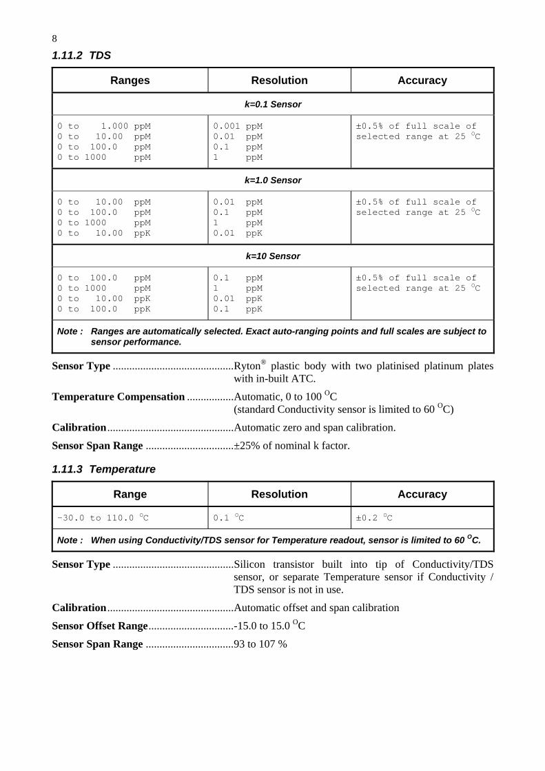
1.11.2 TDS
Ranges Resolution Accuracy
k=0.1 Sensor
0 to 1.000 ppM 0 to 10.00 ppM 0 to 100.0 ppM 0 to 1000 ppM
0.001 ppM 0.01 ppM 0.1 ppM 1 ppM
±0.5% of full scale of selected range at 25 OC
k=1.0 Sensor
0 to 10.00 ppM 0 to 100.0 ppM 0 to 1000 ppM 0 to 10.00 ppK
0.01 ppM 0.1 ppM 1 ppM 0.01 ppK
±0.5% of full scale of selected range at 25 OC
k=10 Sensor
0 to 100.0 ppM 0 to 1000 ppM 0 to 10.00 ppK 0 to 100.0 ppK
0.1 ppM 1 ppM 0.01 ppK 0.1 ppK
±0.5% of full scale of selected range at 25 OC
Note : Ranges are automatically selected. Exact auto-ranging points and full scales are subject to sensor performance.
Sensor Type ............................................Ryton® plastic body with two platinised platinum plates with in-built ATC.
Temperature Compensation .................Automatic, 0 to 100 OC (standard Conductivity sensor is limited to 60 OC)
Calibration..............................................Automatic zero and span calibration.
Sensor Span Range ................................±25% of nominal k factor.
1.11.3 Temperature
Range Resolution Accuracy
-30.0 to 110.0 OC 0.1 OC ±0.2 OC
Note : When using Conductivity/TDS sensor for Temperature readout, sensor is limited to 60 OC.
Sensor Type ............................................Silicon transistor built into tip of Conductivity/TDS sensor, or separate Temperature sensor if Conductivity / TDS sensor is not in use.
Calibration..............................................Automatic offset and span calibration
Sensor Offset Range...............................-15.0 to 15.0 OC
Sensor Span Range ................................93 to 107 %

9
1.11.4 General Specifications Memory ...................................................9990 readings including date and time with A&B function
disabled.
8120 readings including date and time with A&B function enabled.
Automatic Logging.................................Rate per Day 1 to 288 readings per day.
Time of Day 1 to 12 discrete times of the day, in 24 hour format.
Sampling Period and Duration One reading every 1 to 300 seconds for a duration of 1 to 720 minutes or continuous.
RS232 Port ..............................................300, 9600 & 19200 baud. 8 bits, no parity, 1 stop bit, XON/XOFF Protocol.
Clock........................................................Calendar clock displays date, month, hours, minutes & seconds. Year is Y2K compliant and is attached to all stored data.
Good Laboratory Practices ...................Date, time and results of last calibration for Conductivity, TDS and Temperature are stored. This information can be recalled or sent to the RS232 port at any time.
Power.......................................................7.2V, 1300mAH NiCad battery built in.
Battery charger for country of destination is included.
Solar panel and external battery clip lead optionally available.
Battery Saver ..........................................Auto switch-off after 5 minutes or 1 hour. Battery saver can be switched off to allow continuous use.
Dimensions ..............................................230 x 140 x 100 mm
Mass.........................................................Instrument only : Approx. 1.5 kg Full Kit : Approx. 5.0 kg
Environment ...........................................Temperature : 0 to 45 OC Humidity : 0 to 90 % R.H.

10
2. 90-C Menu Structure A detailed breakdown of the menu system of the 90-C is shown below. This diagram provides a quick reference for the menu functions available for the 90-C.
→ F1:Calibrate → F1:Conductivity F1:TDS
F3:Temperature → F2:Mode → F1:Conductivity
F2:TDS → F3:Logger → F1:Recall
F2:Erase → F1:Erase All F2:Erase Last
F3:Print Log
F4:Start or: F4:Stop
F5:Program → F1:Rate per Day F2:Time of Day F3:Sampling Period
and Duration → F4:Setup → F1:Standards → F1:Conductivity F2:TDS
F2:GLP → F1:Recall F3:Print F4:Initialise Meter
F3:Set AB → F1:A=Pond,No B F2:A=Pond,B=Data F3:A=Data,NoB F4:A&B=Data F5:OFF
F4:k factor * → F1:k=.1 * F2:k=1 * F5:System → F1:Bat. Saver → F1:OFF F2:5 minutes F3:1 hour
F2:Set Clock
F3:Baud Rate → F1:300 F2:9600 F3:19200 * This function not available when a TPS k=10 sensor is connected.

11
3. Conductivity Mode 3.1 Selecting Conductivity Mode
1. Select Conductivity Mode ( → F2:Mode → F1:Conductivity).
2. The 90-C now proceeds to Conductivity measurement mode. Note that a “ ∗ ” is shown in place of the decimal point until a successful calibration has been performed (see section 3.4).
3.2 Setting the Conductivity calibration standard The factory default for this item is 2.76mS/cm. If this is satisfactory, go directly to section 3.3. 1. Select the Conductivity Standard entry
( → F4:Setup → F1:Standards → F1:Conductivity).
The following screen is now displayed…
Conductivity Standard:2760 uS Range 20uS/cm to 2000mS/cm
2. Type in the value of the Conductivity standard that is to be used for calibration, including the decimal point. Use the key to make any corrections.
3. Press to save the value of the standard solution.
Alternatively, press to quit without changing the current setting.
4. The 90-C will now ask you to enter the units for the Conductivity standard…
Conductivity Standard:2760 Select Units F1:uS/cm F2:mS/cm
Press to set the Conductivity Standard as µS/cm.
Press to set the Conductivity Standard as mS/cm.
5. The Conductivity standard is now programmed for use at calibration.

12
3.3 Setting the Conductivity sensor k factor The 90-C automatically recognises a k=10 sensor. If a k=10 sensor is being used, go directly to section 3.4.
The 90-C does not automatically recognise k=0.1 or k=1 sensors. When a k=0.1 or k=1 sensor is used, the 90-C must be set to the correct k factor before use.
To select a k=0.1 or k=1 sensor…
1. Select k factor entry ( → F4:Setup → F4:k factor).
2. The k factor entry screen is now displayed…
Select nominal k factor, F1:k=.1 >F2:k=1
The arrow indicates the current selection.
Press if a k=0.1 sensor is being used.
Press if a k=1 sensor is being used.
Press to quit without changing the current setting.
Notes 1. The manual k factor selection is kept in memory when the meter is switched off.
2. The manual k factor selection is reset to k=1 during initialisation.
3. The 90-C will always automatically recognise a k=10 sensor, regardless of the manual k factor selection.
4. Calibration settings for k=0.1, k=1 and k=10 sensors are NOT stored separately.
The 90-C requires re-calibration when a new k factor sensor is connected.

13
3.4 Conductivity Calibration Before attempting a Conductivity calibration, ensure that the 90-C has been set up correctly according to sections 3.1 to 3.3.
1. Plug the Conductivity sensor into the Cond/Sal socket.
2. Rinse the Conductivity sensor in distilled water. Shake off as much water as possible. Blot the outside of the sensor dry. DO NOT BLOT THE ELECTRODE WIRES.
Zero Calibration 3. Let the sensor dry in air.
4. Select Conductivity Calibration ( → F1:Calibrate → F1:Conductivity).
5. The 90-C will recognise the low conductivity signal and attempt a Zero calibration. For example…
0*01uS 25.0oc Cond. ZERO Calibration,Press Enter
6. When the reading has stabilised at or near zero, press to calibrate or to quit. The “ ∗ ” will not be removed after a zero calibration.
Standard Calibration 7. Place the Conductivity sensor into a sample of Conductivity standard. Ensure that it is
immersed correctly, as per the diagram below. DO NOT place the sensor directly into the bottle of standard. Discard the used sample of standard after use.
8. Select Conductivity Calibration ( → F1:Calibrate → F1:Conductivity). The calibration screen will be displayed with the Conductivity standard to be used. For example…
2*86mS 25.0oc Cond. 2760uS Calibration,Press Enter
9. When the reading has stabilised, press to calibrate. The “ ∗ ” will now be replaced by a decimal point if calibration was successful.
10. The 90-C is now calibrated for Conductivity and is ready for use in this mode.
Ensure that the sensor is immersed at least as deeply as per the diagram in step 7 for all sample measurements.

14
3.5 Conductivity Calibration Notes 1. A Zero calibration should be performed at least monthly. In low conductivity applications
(where a zero error is particularly significant), a zero calibration may have to be done weekly.
2. A Standard calibration should be performed at least weekly. Of course, more frequent calibration will result in greater confidence in results.
3. Conductivity and TDS calibration data is stored separately in memory. Ensure that the 90-C has been correctly calibrated for the mode in which it will be used. The 90-C does not require re-calibration when alternating between Conductivity and TDS modes, providing the instrument has been correctly calibrated for each mode on the k factor sensor to be used.
4. All calibration information is retained in memory when the 90-C is switched off. This information can be recalled or printed later using the GLP function (see section 6).
5. The 90-C displays the value of the standard to which it will attempt to calibrate. Ensure that the standard value displayed corresponds to the standard that you are using. Alter the Standards set-up if necessary (see section 3.2).
6. Calibration settings for k=0.1, k=1 and k=10 sensors are NOT stored separately.
The 90-C requires re-calibration when a new k factor sensor is connected.
3.6 Conductivity Calibration Messages 1. If a Zero Calibration has been successfully performed, the 90-C will display the following
message…
0.00uS 25.0oc Calibration OK, Zero=0.01uS
2. If a Standard Calibration has been successfully performed, the 90-C will display the following message and the calculated k factor of the sensor. For example…
2.76mS 25.0oc Calibration OK, k=0.99
3. If a Standard Calibration has failed, the 90-C will display the following message and the calculated k factor of the sensor. For example…
Calibration Failure. Check STD=2760uS/cm k=3.64, Exceeds Limit
Notes 1. The allowable k factor range is +/-25% of nominal. This range is ample to allow for correctly
functioning Conductivity sensors. If calibration fails due to the k factor being outside these limits, then please consult the Troubleshooting guide (section 14.2) for possible remedies.

15
4. TDS Mode 4.1 Selecting TDS Mode
1. Select TDS Mode ( → F2:Mode → F2:TDS).
2. The 90-C now proceeds to TDS measurement mode. Note that a “ ∗ ” is shown in place of the decimal point until a successful calibration has been performed (see section 4.4).
4.2 Setting the TDS calibration standard The factory default for this item is 36.00 ppK. If this is satisfactory, go directly to section 4.3. 1. Select the TDS Standard entry
( → F4:Setup → F1:Standards → F2:TDS).
The following screen is now displayed…
TDS Standard:36.00ppK Range 20 ppM to 500 ppK
2. Type in the value of the TDS standard that is to be used for calibration, including the decimal point. Use the key to make any corrections.
3. Press to save the value of the standard solution.
Alternatively, press to quit without changing the current setting.
4. The 90-C will now ask you to enter the units for the TDS standard…
TDS Standard:36.00 Select Units F1:ppM F2:ppK
Press to set the TDS Standard as ppM (parts per Million).
Press to set the TDS Standard as ppK (parts per Thousand).
5. The TDS standard is now programmed for use at calibration.

16
4.3 Setting the TDS sensor k factor The 90-C automatically recognises a k=10 sensor. If a k=10 sensor is being used, go directly to section 4.4.
The 90-C does not automatically recognise k=0.1 or k=1 sensors. When a k=0.1 or k=1 sensor is used, the 90-C must be set to the correct k factor before use.
To select a k=0.1 or k=1 sensor…
1. Select k factor entry ( → F4:Setup → F4:k factor).
2. The k factor entry screen is now displayed…
Select nominal k factor, F1:k=.1 >F2:k=1
The arrow indicates the current selection.
Press if a k=0.1 sensor is being used.
Press if a k=1 sensor is being used.
Press to quit without changing the current setting.
Notes 1. The manual k factor selection is kept in memory when the meter is switched off.
2. The manual k factor selection is reset to k=1 during initialisation.
3. The 90-C will always automatically recognise a k=10 sensor, regardless of the manual k factor selection.
4. Calibration settings for k=0.1, k=1 and k=10 sensors are NOT stored separately.
The 90-C requires re-calibration when a new k factor sensor is connected.

17
4.4 TDS Calibration Before attempting a TDS calibration, ensure that the 90-C has been set up correctly according to sections 4.1 to 4.3.
1. Plug the TDS sensor into the Cond/Sal socket.
2. Rinse the TDS sensor in distilled water. Shake off as much water as possible. Blot the outside of the sensor dry. DO NOT BLOT THE ELECTRODE PLATES.
Zero Calibration 3. Let the sensor dry in air.
4. Select TDS Calibration ( → F1:Calibrate → F1:TDS).
5. The 90-C will recognise the low TDS signal and attempt a Zero calibration. For example…
0*01ppM 25.0oc TDS ZERO Calibration,Press Enter
6. When the reading has stabilised at or near zero, press to calibrate or to quit. The “ ∗ ” will not be removed after a zero calibration.
Standard Calibration 7. Place the TDS sensor into a sample of TDS standard. Ensure that it is immersed correctly, as
per the diagram below. DO NOT place the sensor directly into the bottle of standard. Discard the used sample of standard after use.
8. Select TDS Calibration ( → F1:Calibrate → F1:TDS). The calibration screen will be displayed with the TDS standard to be used. For example…
36*10ppK 25.0oc TDS 36.00ppK Calibration,Press Enter
9. When the reading has stabilised, press to calibrate. The “ ∗ ” will now be replaced by a decimal point if calibration was successful.
10. The 90-C is now calibrated for TDS and is ready for use in this mode.
Ensure that the sensor is immersed at least as deeply as per the diagram in step 7 for all sample measurements.

18
4.5 TDS Calibration Notes 1. A Zero calibration should be performed at least monthly. In low TDS applications (where a
zero error is particularly significant), a zero calibration may have to be done weekly.
2. A Standard calibration should be performed at least weekly. Of course, more frequent calibration will result in greater confidence in results.
3. Conductivity and TDS calibration data is stored separately in memory. Ensure that the 90-C has been correctly calibrated for the mode in which it will be used. The 90-C does not require re-calibration when alternating between Conductivity and TDS modes, providing the instrument has been correctly calibrated for each mode on the k factor sensor to be used.
4. All calibration information is retained in memory when the 90-C is switched off. This information can be recalled or printed later using the GLP function (see section 6).
5. The 90-C displays the value of the standard to which it will attempt to calibrate. Ensure that the standard value displayed corresponds to the standard that you are using. Alter the Standards set-up if necessary (see section 4.2).
6. Calibration settings for k=0.1, k=1 and k=10 sensors are NOT stored separately.
The 90-C requires re-calibration when a new k factor sensor is connected.
4.6 TDS Calibration Messages 1. If a Zero Calibration has been successfully performed, the 90-C will display the following
message…
0.00ppM 25.0oc Calibration OK, Zero=0.01ppM
2. If a Standard Calibration has been successfully performed, the 90-C will display the following message and the calculated k factor of the sensor. For example…
36.00ppK 25.0oc Calibration OK, k=9.90
3. If a Standard Calibration has failed, the 90-C will display the following message and the calculated k factor of the sensor. For example…
Calibrate Failure. Check STD=36.00ppK k=15.0, Exceeds Limit
Notes 1. The allowable k factor range is +/-25% of nominal. This range is ample to allow for correctly
functioning TDS sensors. If calibration fails due to the k factor being outside these limits, then please consult the Troubleshooting guide (section 14.2) for possible remedies.

19
5. Temperature Mode There are two Temperature sensors built into the tip of the Conductivity/TDS sensor. The first is used for Automatic Temperature Compensation for Conductivity/TDS readings. The second is used for Temperature readout. It is therefore not necessary to calibrate Temperature before taking Conductivity/TDS measurements.
The decimal point is replaced by a “ ∗ ” if the reading is not calibrated.
5.1 Temperature Calibration 1. Plug Conductivity/TDS sensor into the Cond/Sal socket.
2. Switch the meter on.
3. Place the sensor into a beaker of room temperature water, alongside a good quality mercury thermometer. Stir the sensor and the thermometer gently to ensure an even temperature throughout the beaker.
4. Select Temperature Calibration ( → F1:Calibrate → F3:Temperature).
The Temperature Calibration screen is now displayed…
Enter Actual Temperature : _ 24.0Oc Temperature Calibration Menu Quits
5. The current reading from the sensor is displayed on the far right of the top line.
When this reading has stabilised, use the Numeric Keypad to enter the same temperature as measured by the mercury thermometer.
6. Press the key to calibrate the temperature readout.
Alternatively, press the key to abort temperature calibration.
The 90-C is now 1 point temperature calibrated. This will provide precision to approximately ±0.5 OC. The following screen is displayed…
1 Point Calibration OK, Offset=0.1oc Press Enter for Span Cal. or Menu Quits
Press if ±0.5 OC is adequate for your application. The 90-C will now return to normal measurement mode and the “ ∗ ” in the Temperature readout will have been replaced by a decimal point.
Press to go on to a second point calibration if a higher degree of precision is required.
7. When a second point calibration is being performed, the 90-C will now display the second calibration screen..
Enter Actual Temperature : _ 36.0oc 15.0 > Temp > 35.0 Menu Quits
Please note that the sensor must now be placed into a container of water that is at least 10 OC higher or lower than the first calibration point.
An insulated container with around 1 Litre or more of water will provide a stable environment to do the second point Temperature calibration. The Temperature of the water in a small, uninsulated container will change too rapidly, making a successful second point calibration virtually impossible.

20
8. The current reading from the sensor is displayed on the far right of the top line.
When this reading has stabilised, use the Numeric Keypad to enter the same temperature as measured by the mercury thermometer.
9. Press the key to calibrate the temperature readout.
Alternatively, press the key to abort the second point temperature calibration. The first point calibration settings will still be preserved.
10. The 90-C is now Temperature calibrated and is ready for use in this mode.
The full ±0.2 OC accuracy specification will apply after a successful 2 point calibration.
5.2 Temperature Calibration Notes 1. Temperature calibration information is retained in memory when the 90-C is switched off. This
information can be recalled later using the GLP function (see section 6).
2. Temperature does not need to be re-calibrated unless the Conductivity/TDS or Temperature sensor is replaced or the meter is initialised.
5.3 Calibration Messages 1. If a 1 point temperature calibration has been successfully performed, the 90-C will display the
following message and the offset value of the sensor. The bottom line appears after 3 seconds.
1 Point Calibration OK, Offset=0.1oc Press Enter for Span Cal. or Menu Quits
2. If a 1 point temperature calibration has failed, the 90-C will display the following message and the failed offset value of the sensor.
1 Point Calibration Failed, Offset=16.0oc
3. The 90-C has an allowable Offset range of -15.0 to +15.0 OC. If calibration fails due to the Offset being outside these limits, then please consult the Troubleshooting guide (section 14.3) for possible remedies.
4. If a 2 point temperature calibration has been successfully performed, the 90-C will display the following message and the span value of the sensor.
2 Point Calibration OK, Span=101.0%
5. If a 2 point temperature calibration has failed, the 90-C will display the following message and the failed span value of the sensor.
2 Point Calibration Failed, Span=200.0%
6. The 90-C has an allowable span range of 93.0 to 107.0 %. If calibration fails due to the Span being outside these limits, then please consult the Troubleshooting guide (section 14.3) for possible remedies.

21
6. Good Laboratory Practices (GLP) The 90-C keeps a record of the date and time of the last calibrations for Conductivity, TDS and Temperature as part of GLP guidelines.
6.1 To recall GLP information on the display 1. Switch the meter on.
2. Select the GLP menu ( → F4:Setup → F2:GLP).
3. Select F1:Recall from the menu.
4. The instrument model, firmware version number, and instrument serial number are displayed, along with a prompt describing how to scroll through the GLP information.
90C V6.0 S1234 @ 31/12/00 12:00 F4:Next
5. Press the key to sequentially scroll through the GLP information for all parameters. Press the key to scroll back to previous data. The sequence of information displayed is shown below. Press to abort at any time.
GLP Display sequence…
90C V6.0 S1234 @ 31/12/00 12:00 F4:Next
↑ ↓
Cond. Zero=0.01Us 31/12/00 12:00 Cond Calibrated F2:Back F4:Next
↑ ↓
Cond. k=10.1 31/12/00 12:10 Cond Calibrated F2:Back F4:Next
↑ ↓
TDS Zero=0.01ppM 31/12/00 12:00 TDS Calibrated F2:Back F4:Next
↑ ↓
TDS k=10.1 31/12/00 12:20 TDS Calibrated F2:Back F4:Next
↑ ↓
Temperature Offset=1.0Oc 31/12/00 12:30 Temp Probe Calibrated F2:Back F4:Next
↑ ↓
Temperature Span=100.0% 31/12/00 12:40 Temp Probe Calibrated F2:Back F4:Ends

22
6.2 Failed Calibration If calibration has failed, the GLP function will reset the date and time for the failed parameter to zero. The 90-C still shows the results for the last successful calibration, as shown in the following example of a failed Conductivity calibration….
Cond. k=3.64 00/00/00 00:00 Cond. Un-Calibrated F2:Back F4:Next
6.3 Printing GLP Information to the RS232 Port The GLP information stored in the instrument’s memory can be sent to a printer or PC via the RS232 port.
1. Switch the meter on.
2. Connect one end of the RS232 cable to the Charger socket of the 90-C. The battery charger, optional battery adaptor, or optional solar panel may be connected to the in-line socket on the RS232 cable, if required.
3. Connect the other end of the RS232 cable to an RS232 Printer, or to the COM1 or COM2 ports of a PC.
4. Send the GLP information to the RS232 port:
→ F4:Setup → F2:GLP → F3:Print (or )
The message “Printing GLP Data” is displayed while sending the data to the RS232 port.
5. The GLP information is sent to the RS232 port in formatted ASCII text. For example… 90C V6.0 S1234 @ 31/12/2000 12:00 Conductivity Zero= 0.01uS @ 31/12/2000 12:00 Conductivity k= 1.01 @ 31/12/2000 12:10 TDS Zero= 0.01ppM @ 31/12/2000 12:00 TDS k= 1.01 @ 31/12/2000 12:20 Temperature Offset= 1.0oC @ 31/12/2000 12:30 Temperature Span= 100.0% @ 31/12/2000 12:40 Ends

23
6.4 Instrument Serial Number In case the serial number that is fitted to the rear of the 90-C is removed or becomes illegible, it is also available on the 90-C display.
1. The serial number is displayed at turn-on, for example…
90C V6.0 S1234 (c) 2001 TPS Pty Ltd Conductivity, TDS, Temperature Logger
2. The serial number is displayed when recalling the GLP information (section 6.1).
3. The serial number is included on the print-out of GLP information (section 6.3).
4. The GLP information can be downloaded to a PC using the optional Windows® software (part number 130086).
6.5 Additional GLP Features Another GLP requirement is to record the date and time of every reading. The 90-C does this for you when readings are recorded either with the Manual Datalogging function (section 7.2) or the Automatic Datalogging function (section 7.3).
24
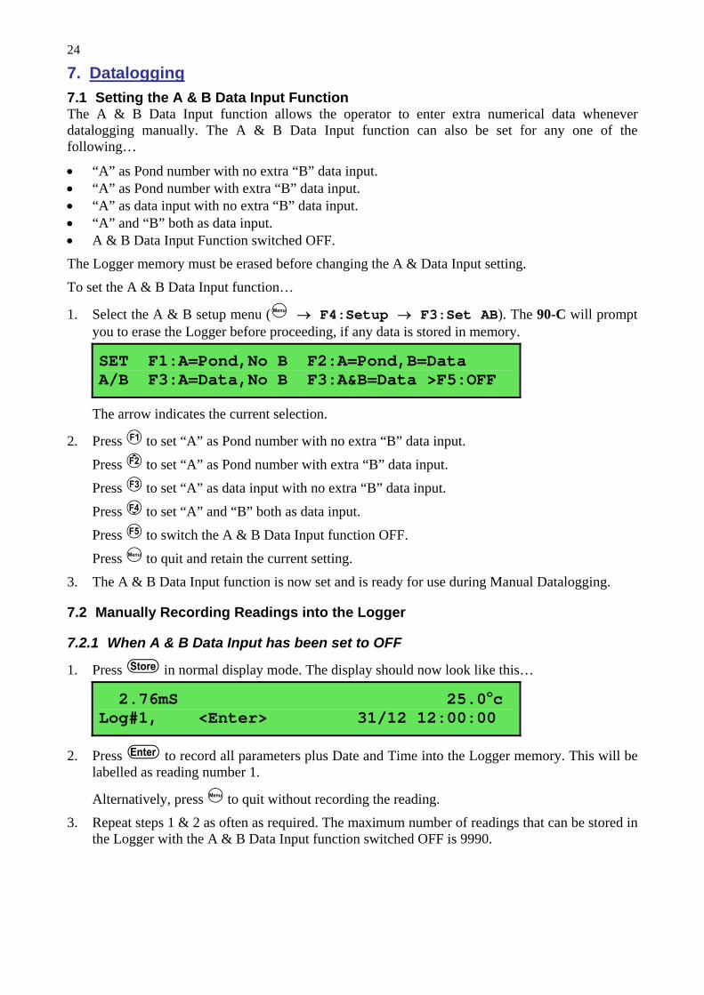
7. Datalogging 7.1 Setting the A & B Data Input Function The A & B Data Input function allows the operator to enter extra numerical data whenever datalogging manually. The A & B Data Input function can also be set for any one of the following…
• “A” as Pond number with no extra “B” data input. • “A” as Pond number with extra “B” data input. • “A” as data input with no extra “B” data input. • “A” and “B” both as data input. • A & B Data Input Function switched OFF.
The Logger memory must be erased before changing the A & Data Input setting.
To set the A & B Data Input function…
1. Select the A & B setup menu ( → F4:Setup → F3:Set AB). The 90-C will prompt you to erase the Logger before proceeding, if any data is stored in memory.
SET F1:A=Pond,No B F2:A=Pond,B=Data A/B F3:A=Data,No B F3:A&B=Data >F5:OFF
The arrow indicates the current selection.
2. Press to set “A” as Pond number with no extra “B” data input.
Press to set “A” as Pond number with extra “B” data input.
Press to set “A” as data input with no extra “B” data input.
Press to set “A” and “B” both as data input.
Press to switch the A & B Data Input function OFF.
Press to quit and retain the current setting.
3. The A & B Data Input function is now set and is ready for use during Manual Datalogging.
7.2 Manually Recording Readings into the Logger
7.2.1 When A & B Data Input has been set to OFF
1. Press in normal display mode. The display should now look like this…
2.76mS 25.0oc Log#1, <Enter> 31/12 12:00:00
2. Press to record all parameters plus Date and Time into the Logger memory. This will be labelled as reading number 1.
Alternatively, press to quit without recording the reading.
3. Repeat steps 1 & 2 as often as required. The maximum number of readings that can be stored in the Logger with the A & B Data Input function switched OFF is 9990.

25
7.2.2 When A is set to Pond, with no extra B data
1. Press in normal display mode. The display should now look like this…
2.76mS 25.0oc Log#1, Pond#1 31/12 12:00:00
2. Use the numeric keypad to key in the Pond number, then press to record all parameters, Date, Time and the Pond number into the Logger memory. This will be labelled as reading number 1.
Alternatively, press to quit without recording the reading.
3. Repeat steps 1 & 2 as often as required.
The Pond number will automatically increment by one from the last recorded reading.
The maximum number of readings that can be stored in the Logger with this A & B Data Input setting is 8120.
7.2.3 When A is set to Pond, and B is set to data
1. Press in normal display mode. The display should now look like this…
2.76mS 25.0oc Log#1, Pond#1 31/12 12:00:00
2. Use the numeric keypad to key in the Pond number, then press to record all parameters, Date, Time and the Pond number into the Logger memory. This will be labelled as reading number 1.
Alternatively, press to quit without recording the reading.
3. The 90-C now proceeds to the B data entry screen…
Data Recorded, Now Input B or Press Menu Enter Data B:0
Use the numeric keypad to key in up to four characters for the “B” data item. The decimal point is available. Press to record the “B” data item, or press to quit. Quitting at this point records a Zero as the “B” data item.
4. Repeat steps 1 to 3 as often as required.
The Pond number will automatically increment by one from the last recorded reading.
The maximum number of readings that can be stored in the Logger with this A & B Data Input setting is 8120.

26
7.2.4 When A is set to Data with no B data 1. Press in normal display mode. The display should now look like this…
2.76mS 25.0oc Log#1, <Enter> 31/12 12:00:00
2. Press to record all parameters, plus Date and Time into the Logger memory. This will be labelled as reading number 1.
Alternatively, press to quit without recording the reading.
3. The 90-C now proceeds to the A data entry screen…
Enter Data A:0 Data Recorded, Now Input A or Press Menu
Use the numeric keypad to key in up to four characters for the “A” data item. The decimal point is available. Press to record the “A” data item, or press to quit. Quitting at this point records a Zero as the “A” data item.
4. Repeat steps 1 to 3 as often as required.
The maximum number of readings that can be stored in the Logger with this A & B Data Input setting is 8120.
7.2.5 When A and B are both set to Data 1. Press in normal display mode. The display should now look like this…
2.76mS 25.0oc Log#1, <Enter> 31/12 12:00:00
2. Press to record all parameters, plus Date and Time into the Logger memory. This will be labelled as reading number 1.
Alternatively, press to quit without recording the reading.
3. The 90-C now proceeds to the A data entry screen…
Enter Data A:0 Data Recorded, Now Input A or Press Menu
Use the numeric keypad to key in up to four characters for the “A” data item. The decimal point is available. Press to record the “A” data item, or press to quit. Quitting at this point records Zero’s as the “A” and “B” data items.
4. The 90-C now proceeds to the B data entry screen…
Enter Data A:1234 Enter Data B:0
Use the numeric keypad to key in up to four characters for the “B” data item. The decimal point is available. Press to record the “B” data item, or press to quit. Quitting at this point records a Zero as “B” data item.
5. Repeat steps 1 to 4 as often as required.
The maximum number of readings that can be stored in the Logger with this A & B Data Input setting is 8120.

27
7.3 Automatic Datalogging The 90-C can automatically log records into the Logger. There are three automatic datalogging modes to choose from…
1. Rate Per Day • Logs from 1 to 288 readings per day, evenly spaced throughout each 24 hour period. • Unit is dormant between readings and “wakes up” when a reading is due. • Unit continues to log until automatic datalogging is disabled, or until the memory is full.
2. Time of Day • Logs at up to12 discrete times of the day, which can be unevenly spaced throughout each 24
hour period. • Unit is dormant between readings and “wakes up” when a reading is due. • Unit continues to log until automatic datalogging is disabled, or until the memory is full.
3. Sampling Period and Duration • Logs a reading every 1 to 300 seconds for a duration of 1 to 720 minutes. • Duration can be set to log continuously until the memory is full. • Unit is turned on continuously in this logging mode.
The automatic datalogging parameters of the 90-C must first be programmed, then logging can be started and stopped as required.

28
7.3.1 Rate per Day Datalogging Programming Rate per Day Datalogging
1. Select the Logger Program menu ( → F3:Logger F5:Program)
2. Select F1:Rate per Day from the menu. The display should now look similar to that shown below. The current Rate per Day is displayed…
Number of Readings per Day : 24
3. Use the Numeric Keypad to set the number of readings per day which the 90-C will automatically log into memory. This can be set from 1 to 288 (ie. 1 reading every 24 hours to 1 reading every 5 minutes).
Press to save the Rate per Day.
Press to quit without changing the current setting.
4. The Rate per Day datalogging is now programmed, and can be started and stopped as required.
Notes 1. The 90-C distributes the number of readings evenly throughout a 24 hour clock cycle,
regardless of what time automatic logging is started and stopped. For example, if the 90-C is programmed to log 4 readings per day, they will be logged at 24:00, 6:00, 12:00 and 18:00 o’clock.
Starting and Stopping Rate per Day Datalogging
Starting Rate per Day datalogging is a two step process…
1. Select the Logger menu ( → F3:Logger)
Select F4:Start from the menu.
2. Switch the 90-C OFF. This step is essential, as the Rate per Day datalogging is only enabled when the 90-C is switched OFF.
Stopping Rate per Day datalogging is a one step process…
1. Select the Logger menu ( → F3:Logger)
Select F4:Stop from the menu.
Notes 1. The 90-C remains dormant between readings and only switches itself ON when a reading is
due.

29
7.3.2 Time of Day Datalogging Programming Time of Day Datalogging
1. Select the Logger Program menu ( → F3:Logger F5:Program)
2. Select F2:Time of Day from the menu. The display should now look similar to that shown below. Any currently programmed times are displayed…
Log 00:00 00:00 00:00 00:00 00:00 00:00 Time 00:00 00:00 00:00 00:00 00:00 00:00
3. Use the Numeric Keypad to set the first time of the day at which the 90-C will automatically log into memory.
4. Press to move to the next time of the day.
5. Repeat steps 7 and 8 to enter up to 12 times of the day. The times do not need to be evenly spread throughout the day. Times must be entered in 24 hour clock format.
6. Press to save the programmed times of the day and quit.
7. The Time of Day datalogging is now programmed, and can be started and stopped as required.
Notes 1. For 12:00 o’clock midnight, enter the time as “24:00”.
2. The times of the day do not need to be entered in chronological order. The 90-C will sort them after pressing .
Starting and Stopping Time of Day Datalogging
Starting Time of Day datalogging is a two step process…
1. Select the Logger menu ( → F3:Logger)
Select F4:Start from the menu.
2. Switch the 90-C OFF. This step is essential, as the Time of Day datalogging is only enabled when the 90-C is switched OFF.
Stopping Time of Day datalogging is a one step process…
1. Select the Logger menu ( → F3:Logger)
Select F4:Stop from the menu.
Notes 1. The 90-C remains dormant between readings and only switches itself ON when a reading is
due.

30
7.3.3 Sampling Period and Duration Datalogging Programming Sampling Period and Duration Datalogging
1. Select the Logger Program menu ( → F3:Logger F5:Program)
2. Select F3:Sampling Period and Duration from the menu.
3. The 90-C now prompts you to enter the sampling period in seconds. The current sampling period is displayed…
Enter Sampling Period (secs) : 5
Use the Numeric Keypad to set the 90-C to log a reading every 1 to 300 seconds.
Press to save the new sampling period and move to setting the duration.
Press to retain the previous sampling period and move to setting the duration.
4. The 90-C now prompts you to enter the duration in minutes. The current duration is displayed…
Enter Duration of Sampling (mins) : 10 Enter 0 for continuous
Use the Numeric Keypad to set the total duration for which the 90-C will log readings into memory from 1 to 720 minutes. Alternatively, enter 0 to log continuously until logging is stopped by the user or the memory is full.
Press to save the new duration.
Press to quit and retain the previous duration.
5. The Sampling Period and Duration datalogging is now programmed, and can be started and stopped as required.
Starting and Stopping Sampling Period and Duration Datalogging
Starting and stopping Sampling Period and Duration datalogging is a two step process…
1. Press in normal measurement mode.
2. The 90-C now prompts you to press to begin logging. For example…
Press Enter to Sample every 5 seconds, For 10 minutes, or Menu to Quit 12:00:00
The time is shown to enable the user to synchronise the sampling times if required.
2. Press to start logging.
To stop logging before the end of the duration press .
Notes 1. The 90-C remains switched on continuously for Sampling Period and Duration datalogging.

31
7.4 Recalling Readings from the Logger To recall records from the Logger onto the 90-C display…
1. Select the Logger menu ( → F3:Logger)
2. Select F1:Recall from the menu.
Record number 1 is now displayed.
The following example shows the display when the A & B Data Input function was switched off during logging…
2.76mS 25.0oc Log#1 F2:↑ F4:↓ 31/12 12:00:00
The following example shows the display when “A” and “B” were both set to data during logging…
2.76mS 25.0oc Log#1 A=1234 B=1234 31/12 12:00:00
3. Press to display the next record.
Press to display the previous record.
Press and hold or to scroll continuously through the readings. To display a specific record, type in the desired record number using the Numeric Keypad and press .
Press to send the displayed record to the RS232 port.

32
7.5 Erasing Records from the Logger To erase records from the Logger…
1. Select the Erase Logger menu ( → F3:Logger → F2:Erase)
2. The 90-C now displays the Erase menu, for example…
Erase Logger, ( 100 ) Select Option F1:Erase All F2:Erase Last Menu Exits
The number of readings stored in the Logger is displayed. See the “100” in the example above.
3. Press to erase all of the readings stored in the Logger.
Press to erase the last recorded reading only.
Press to quit without erasing any records.
7.6 Printing Records from the Logger to the RS232 Port 1. Connect one end of the RS232 cable to the Charger socket of the 90-C.
2. Connect the other end of the RS232 cable to an RS232 Printer, or to the COM1 or COM2 ports of a PC.
3. Ensure that the baud rate for the printer or PC and the 90-C are the same. If necessary, alter the baud rate of the 90-C (see section 8.1).
The 90-C uses XON/XOFF protocol. Ensure that the printer is set accordingly.
4. Select the Logger menu. ( → F3:Logger).
5. Select F3:Print Log (or ) from the menu.
6. Printing starts as soon as (or ) is pressed. The display shows the word “Printing” until printing is completed.

33
8. RS232 Port
8.1 Setting the Baud Rate 1. Select the Baud Rate menu ( → F5:System → F3:Baud Rate)
2. The available baud rates are listed, along with the RS232 port configuration…
Baud Rate: F1:300 >F2:9600 F3:19200 8 bits, No Parity, 1 Stop bit, XON/XOFF
The arrow indicates the current selection.
3. Press to select 300 baud.
Press to select 9600 baud.
Press to select 19200 baud.
Press to quit and retain the current setting.
8.2 Sending Readings to the RS232 Port Press to instantly send readings to the RS232 port whenever the 90-C is in normal display mode.
Each time the 90-C logs a reading, that reading is sent directly to the RS232 port.
Press while recalling data on the display (see section 7.4) to send that record to the RS232 port.
8.3 RS232 Configuration The 90-C RS232 configuration is 8 Bits, No Parity, 1 Stop Bit, XON/XOFF Protocol.
This information is displayed when setting the baud rate (see section 8.1)
8.4 Communication and Statistical Software Communication between the 90-C and a PC can be handled with any RS232 communication software. A TPS communication software package for Windows® is optionally available (part number 130086).
Once the data is saved to disk, the next problem is how to use it. The data sent by the 90-C is formatted in fixed-width columns that can be imported by programs such as Microsoft® Excel® and Lotus 123®.
Help on importing the data into Microsoft® Excel® is provided in section 8.8 and the “excel.txt” file in the folder where you installed the WinTPS program.
8.5 Commands The following commands can be sent from a PC to the 90-C. Note that <cr> denotes carriage return and <lf> denotes a line feed.
Action Command Notes
Request current data ?D<cr> Returns the current data of all parameters plus date and time from the 90-C. The log number returned is set to Zero.
Request logged data ?R<cr> Returns all logged records from the 90-C memory. The data ends with the message ENDS<cr> .
Erase logged data ?E<cr> Erases all logged records from the 90-C memory. Returns the message ERASED<cr> to confirm that the records have been erased.
Continued over the page…

34
RS232 Commands, continued…
Returns the model name, firmware version number, instrument serial number and number of logged readings in memory, for example… 90C•V6.0•S1234•2032•ALB+v%<cr> where • are spaces. Note that the number of logged readings is right-justified. The meaning of the last group of characters is as follows… A or P A indicates A & B function is enabled.
P indicates A is set to Pond Number. L Automatic datalogging is enabled. B Low Battery warning. + Extended datalogging function is fitted. v Battery volts is available with ?V command.
Request status information ?S<cr>
% Indicates new 90 series, V6.0 and up. Request GLP information ?G<cr> Returns all calibration GLP information, plus the instrument
model, serial number and current date (see section 8.7 for data format and hand-shaking).
Enable Rate per Day or Time of Day automatic datalogging
?J<cr> Starts automatic datalogging when the 90-C is set up for Rate per Day or Time of Day automatic datalogging (see sections 7.3.1 and 7.3.2). The meter must then be powered down with the OFF key or with the ?K command (see below).
Disable Rate per Day or Time of Day automatic datalogging
?F<cr> Stops automatic datalogging when the 90-C is set up for Rate per Day or Time of Day automatic datalogging (see sections 7.3.1 and 7.3.2).
Power ON Any 10 characters
Switches the 90-C ON.
A specific command is not available while the 90-C is off, so RS232 activity caused by the 10 characters switches the unit ON.
Power OFF ?K<cr> Switches the 90-C OFF. Use the command after the ?G command (above) to actually start rate per Day or Time of Day automatic datalogging.
Request battery volts ?V<cr> Returns the current voltage level in the battery pack, for example… 7.20V<cr>
Positions of Data Fields ?P<cr> Returns the number of data fields, along with their position and length. When the A&B Data Input function is disabled… 5,1,10,12,8,21,4,26,7,37,5
This denotes 7 fields, the first of which is at column 1 and is 10 characters long. The second field is at column 12 and is 8 characters long and so on. When the A&B Data Input function is enabled… 7,1,10,12,8,21,4,26,7,37,5,45,4,51,4
Data Column Header ?H<cr> Returns a text string which can be used to provide headers for each data field. Spaces are included to ensure that the headers are correctly aligned with the data.

35
8.6 Data Format Data is returned to the RS232 Port by the 90-C in the following format.
Please note that a “ • ” shown anywhere in this section denotes one space. dd/mm/yyyy•hh:mm:ss•LLLL•CCCCCCCuuu•TTTTTuuLaaaaA•bbbbB
where….
dd/mm/yyyy is the date, month and year data.
hh:mm:ss is the hours, minutes and seconds data.
LLLL is the Log Number, 4 characters, right justified. The 90-C sends a Zero for instant readings (see section 8.2).
CCCCCCC is Conductivity or TDS data. 7 characters, right justified.
uuu is the Conductivity/TDS units description, which can be either of the following…
uS• for µS/cm Conductivity readout. All readings are converted to µS/cm to ensure that the data is logical when analysed with other programs.
ppM for parts per Million TDS readout. All readings are converted to ppM to ensure that the data is logical when analysed with other programs.
TTTTT is Temperature data, 5 characters, right justified.
uu is the Temperature unit description. Sent as “oC”.
L is the Low Battery indicator. Sent as “L” when the battery is below 5.60 volts.
Caution : Data recorded with a low battery may be unreliable.
The 90-C sends a space when the battery is above 5.60 volts.
aaaa A-Data input, 4 characters, left justified.
A A-Data input identifier. Sent as “A” for A-Data or “P” for Pond number. See section 7.1 for further details on the A and B Data input function.
bbbb B-Data input, 4 characters, left justified.
B B-Data input identifier. Sent as “B”. See section 7.1 for further details on the A and B Data input function.
Notes 1. The “aaaaA” and “bbbbB” sections of the data string are not sent at all when the A and B
data input function is switched off (see section 7.1).
2. When requested by a PC with the ?D or ?R commands (section 8.5), the data is terminated with a carriage return.
3. When the data is sent by the 90-C using the Print function (section 7.6) or the Instant Send function (section 8.2), the data ends with a carriage return and a line feed.

36
8.7 GLP Data Format GLP information is returned as 12 lines terminated by a carriage return. When using the “?G” command (section 8.5), the computer must respond with a character after receiving each line.
For example… 90C V6.0 S1234 @ 31/12/2000 12:00 Conductivity Zero= 0.01uS @ 31/12/2000 12:00 Conductivity k= 1.01 @ 31/12/2000 12:10 TDS Zero= 0.01ppM @ 31/12/2000 12:00 TDS k= 1.01 @ 31/12/2000 12:20 Temperature Offset= 1.0oC @ 31/12/2000 12:30 Temperature Span= 100.0% @ 31/12/2000 12:40 Ends
8.8 Importing Data into Microsoft Excel The following procedure details the method for importing a 90-C text data file into Microsoft® Excel®.
1. Start Microsoft® Excel® and select File → Open
2. In the “Files of type:” pull-down box, choose “Text Files (*prn; *.txt; *.csv)”.
3. Navigate to the folder where your data file is stored and double-click it to start the Text Import Wizard.
Note : The default data folder for the WinTPS software is “C:\My Documents\WinTPS”.
4. In step 1 of the Text Import Wizard select “Fixed width”, as per the sample screen below, then press “Next >”.
Note that the data column headers in row appear only when the data is downloaded using the WinTPS software.
Continued over the page…

37
5. Step 2 of the Text Import Wizard allows you to select the points at which each data field will break into a new column. The sample screens below show where TPS recommends the breaks be inserted.
The date and time have been incorporated into a single column to ensure that the X-axis is correctly formatted if the data is to be charted later.
Press “Next >” after all the column breaks have been inserted.
6. Simply press “Finish” at step 3 of the Text Import Wizard. TPS recommends that the data
format for each column be set once the data is in spreadsheet format.
For help on formatting the data columns, charting, graphing or other operations please consult the Microsoft® Excel® help file. Alternatively please contact TPS and we will try to provide further assistance.

38
9. Setting the Clock 1. Select the Clock Set-up menu ( → F5:System → F2:Set Clock)
2. The display now shows the current time, for example…
Time is now 12:00 Enter new Time 12:00
3. Use the Numeric Keypad to enter the current time in 24 hour format, then press .
Alternatively, press to quit and retain the current setting.
4. If you pressed above, the display will now show the current date, for example…
Date is now 31/12/2000 Enter new Date 31/12/2000 dd/mm/yyyy
5. Use the Numeric Keypad to enter the current date in dd/mm/yyyy format, then press .
Alternatively, press to quit and retain the current setting.
Notes
1. Press the key to make any corrections as required.
2. The 90-C tests that a valid time of the day is entered. If an invalid time is entered (eg. 25:00), the 90-C displays the message “Invalid Time”, then returns to the time setting screen so that the correct time can be entered.
3. The 90-C tests that a valid day of the month is entered. If an invalid date is entered (eg. 31/02/2001), the 90-C displays the message “Invalid Date”, then returns to the date setting screen so that the correct date can be entered.
4. The 90-C also tests for leap years.

39
10. Initialising the 90-C If the calibration settings of the 90-C exceed the allowable limits, the unit may need to be initialised to factory default values. This action may be required if a sensor is replaced or if the memory is corrupted.
To initialise the 90-C…
1. Select the GLP menu ( → F4:Setup → F2:GLP).
2. Select F4:Initialise Meter from the menu.
3. The 90-C will now ask if you are sure that you wish to initialise the unit…
Initialise Unit, Are you sure ? F1:Yes F2:No
Press to initialise the 90-C and reset all calibration data and erase all logged readings.
Press to quit and retain the current calibration settings and logged readings.
4. If F1:Yes was selected above, the 90-C will display the number of logged readings in memory and provide an additional warning that these will be erased. For example…
Logger contains Data. 2032 readings will be Erased. Continue ? F1:Yes F2:No
Press to initialise the 90-C and reset all calibration data and erase all logged readings.
Press to quit and retain the current calibration settings and logged readings.
5. If F1:Yes was selected above, the 90-C will display the following messages to indicated that the unit has been successfully initialised.
Initialising
then…
Initialised Re-Calibrate unit before use.
6. The meter then goes back to the GLP menu. When returning to display mode later, note that each of the decimal points has been replaced with a “ ∗ ” to indicate that each parameter requires re-calibration.
11. Instrument firmware version number If you need to phone or fax TPS for any further technical assistance, the version number of your 90-C firmware may of benefit to us. The version number is displayed by the 90-C at turn-on.

40
12. Battery Saver Function The 90-C is equipped with a battery saver function. If no button has been pressed for 5 minutes or 1 hour , the unit beeps and flashes the display for 20 seconds and then shuts off. This function can also be switched off for continuous use.
To program the battery saver function:
1. Select Battery Saver menu ( → F5:System → F1:Bat. Saver).
2. The battery saver menu is now displayed…
Battery Saver: F1:OFF >F2:5 minutes Volts= 7.20V F3:1 hour
The arrow indicates the current selection.
3. Press to disable the battery saver function for continuous use.
Press to set the battery saver function to 5 minutes. The meter will switch itself off if no key has been pressed for five minutes.
Press to set the battery saver function to 1 hour. The meter will switch itself off if no key has been pressed for 1 hour.
Press to quit the battery saver menu and retain the current setting.
Notes
1. The symbol flashes when the battery volts drops below 5.60 volts. At approximately 5.10 volts the meter turns itself off.
2. The accuracy of the data degrades when the symbol is flashing. The 90-C should not be used to take readings or calibrate while the is flashing.

41
13. Moisture Protection 13.1 Silica Gel Pack Due to the size of the 90-C enclosure, it tends to expand in hot environments and contract in cold environments. This process can cause moist air to be drawn into the enclosure, which would then cause corrosion damage to the circuit.
To avoid this problem, TPS has mounted a breathing system inside the enclosure. This system consists of a long, thin tube which is vented to the atmosphere at one end and into a bottle of Silica gel at the other end. This ensures that the 90-C breathes dry air. In humid environments, the Silica gel pack should be regularly checked.
To check the Silica gel pack…
1. Undo the 4 plastic screws on the rear of the unit.
2. Inspect the bottle of Silica gel.
Blue indicates that the Silica gel is still dry (proceed to step 5).
Pink indicates that the Silica gel is moist (proceed to step 3).
3. Empty the Silica gel into a microwave proof dish and place it into a microwave oven.
Place approximately 100mL water in a microwave proof cup into the microwave oven. This will absorb some of the microwave energy and stop the Silica gel balls bursting.
Turn the microwave oven ON using a moderate setting for approximately 1 minute, or until the Silica gel turns blue.
CAUTION : THE SILICA GEL MAY BE VERY HOT AT THIS POINT. 4. Remove the Silica gel from the microwave oven and allow to cool.
Pour the Silica gel back into the bottle and re-fit the bottle onto the rear cover of the instrument.
5. Re-fit the rear cover onto the instrument, ensuring that is the correct way around. The cover has locating lugs in two of the corners to make correct fitment simple.
13.2 Corrosion Inhibitor Tab To provide extra protection against corrosion, the 90-C is fitted with a Senson® Vapaguard™ corrosion inhibitor tab. This tab disperses a special vapour throughout the enclosure which actively fights corrosion on any of the components.
The corrosion inhibitor tab has a limited life and should be replaced every 2 to 3 years to ensure effective protection.
The TPS part number for a new corrosion inhibitor tab is NRP2.

42
14. Troubleshooting
14.1 General Errors
Error Message Possible Causes Remedy Factory Calibration Data Failure
The EEPROM chip which contains the factory calibration information has failed.
The unit must be returned to TPS for service.
EEPROM Write Failure
Return to Factory for Service
User calibration settings have been lost or corrupted.
Switch the meter OFF and switch back ON. If the problem persists, return the unit to TPS for service.
Flashing symbol. Battery is below 5.60 volts. Recharge the battery. A full charge will
take approximately 18 hours. Note that the unit will switch itself off when the battery falls below 5.10 volts.
Data obtained while the is flashing may be unreliable. Do not take readings or
calibrate while the is flashing.
Meter displays the word OFF, and switches off.
Battery is below 5.10 volts. Recharge the battery. If this fails, check the charger. If charger is OK, replace the battery.
Meter will not turn on. Battery is exhausted. Recharge the battery for approximately 18 hours. If this fails, check the charger. If charger is OK, replace the battery.
Battery does not charge up when charger is connected.
1. Faulty battery charger. 2. Faulty battery.
1. Connect the charger and switch the power on.
2. Display the battery volts in the battery saver menu (see section 12).
3. If the battery volts are increasing then the charger is OK. If the battery volts do not increase, then the charger is faulty.
4. Replace the charger or the battery, as required.

43
14.2 Conductivity / TDS Troubleshooting
Symptom Possible Causes Remedy Unit fails to calibrate, even with new probe.
Calibration settings outside of allowable limits due to previous failed calibration.
Check that the k factor is set correctly when not using a TPS k=10 sensor. Initialise the unit. See section 10.
Unit attempts Span calibration instead of Zero calibration.
Sensor has Zero error. Thoroughly rinse sensor in distilled water and allow to completely dry in air before attempting zero calibration. DO NOT rub the platinised electrode surfaces. If instrument does not calibrate at Zero with sensor disconnected, then the instrument is faulty.
Standard calibration fails, and k factor is greater than 25% above the nominal value.
1. Sensor is not immersed correctly.
2. Sensor may have a build-up of dirt or oily material on electrode plates.
3. Platinum-black coating has worn off.
4. Standard solution is
inaccurate. 5. Sensor is faulty. 6. Faulty instrument.
Immerse sensor correctly as per diagrams in section 3.4. Clean sensor as per the instructions detailed in section 15.1. Sensor requires replatinization as per section 15.1. Alternatively, return to the factory for replatinization. Replace standard solution. Return sensor to factory for repair or replacement. Return to factory for repair.
Standard calibration fails, and k factor is greater than 25% below the nominal value.
1. Standard solution is inaccurate.
2. Sensor may have a build-up of conductive material, such as salt.
3. Sensor is faulty. 4. Faulty instrument.
Replace standard solution. Clean sensor as per the instructions detailed in section 15.1. Return sensor to factory for repair or replacement. Return to factory for repair.
Inaccurate readings, even when calibration is successful.
1. Sensor may have a build-up of dirt or oily material on electrode plates.
2. Platinum-black coating has worn off.
Clean sensor as per the instructions detailed in section 15.1. Sensor requires replatinization as per section 15.1. Alternatively, return to the factory for replatinization.
Readings drift. Sensor may have a build-up of dirt or oily material on electrode plates.
Clean sensor as per the instructions detailed in section 15.1.
Readings are low or near zero.
1. Sensor may have a build-up of dirt or oily material on electrode plates.
2. Sensor is not immersed correctly.
3. Sensor is faulty. 4. Faulty instrument.
Clean sensor as per the instructions detailed in section 15.1. Immerse sensor correctly as per diagrams in section 3.4. Return sensor to factory for repair or replacement. Return to factory for repair.

44
14.3 Temperature Troubleshooting
Symptom Possible Causes Remedy Temperature inaccurate and cannot be calibrated.
1. Faulty connector. 2. Faulty sensor.
Check the connector and replace if necessary. Return Conductivity sensor for repair, or replace sensor.
Displays OVRoc when Conductivity sensor is plugged in.
1. Faulty instrument socket. 2. Faulty sensor.
Return the instrument to the TPS factory for service. Return Conductivity sensor for repair, or replace sensor.
NOTE Conductivity and TDS readings may still be accurate, as there is a separate temperature sensor to provide ATC for these parameters built into the Conductivity/TDS sensor.

45
15. Appendices
15.1 Care, Cleaning and Maintenance of Conductivity Sensors 15.1.1 Care of Conductivity sensors The conductivity section of the sensor supplied with your 90-C consists of two platinum plates that are plated with a layer of “platinum-black”. This is quite a soft layer and is required for stable, accurate measurements. In time, the platinum-black layer may wear off in some applications, at which time the sensor will require replatinising (see detail later in this section). You can help to maintain the platinum-black layer by following these simple rules:
1. NEVER touch or rub the electrode plates with your fingers, cloth etc.
2. Avoid using the sensor in solutions that contain a high concentration of suspended solids, such as sand or soil, which can abrade the electrode plates. Filter these types of solutions first if possible.
3. Avoid concentrated acids. If you must measure acids, remove the sensor immediately after taking the measurement and rinse well with distilled water.
Conductivity sensors can be stored dry. Ensure that the sensor is stored in a covered container, to avoid dust and dirt build-up.
15.1.2 Cleaning of Conductivity Sensors. Platinised platinum Conductivity sensors can only be cleaned by rinsing in a suitable solvent.
DO NOT wipe the electrode plates, as this will remove the platinum-black layer.
1. Rinsing in distilled water will remove most build-ups of material on the electrode plates.
2. Films of oils or fats on the electrode plates can usually be removed by rinsing the sensor in methylated spirits.
3. Stubborn contamination can be removed by soaking the sensor in a solution of 1 part Concentrated HCl and 10 parts distilled water. The sensor should not be soaked for more than approximately 5 minutes, otherwise the platinum-black layer may start to dissolve.
4. If all of these methods fail, then the last resort is to physically scrub the electrode plates, which will remove the contaminant and the layer of platinum-black. Use only a cloth or nylon scouring pad. DO NOT USE STEEL WOOL. The sensor will then need to be cleaned in HCl, as per step 3 and replatinised (see detail later in this section).

46
15.1.3 Replatinising Conductivity Sensors There are several ways to replatinise Conductivity electrodes.
1. The simplest way is to return the electrode to the TPS factory. We can fully clean the electrode, replatinise it and test all aspects of its performance.
2. An automatic replatiniser is available from TPS, along with replatinising solution. This will plate the electrodes for the right amount of time at the correct current. Ordering details are as follows…
Automatic Conductivity Electrode Replatiniser Part No 122160 20mL Platinising Solution (suitable for approx 30 uses) Part No 122300
3. Conductivity electrodes can be manually replatinised, according to the following procedure…
(a) Soak the electrode in a solution of 1 part Concentrated HCl and 10 parts distilled water for approximately 5 minutes.
(b) Rinse the electrode well in distilled water.
(c) Immerse the electrode in platinising solution at least to the vent hole in the body. Platinising solution is available from TPS (part no 122300). Alternatively, platinising solution can be prepared by dissolving 1g of Hydrogen Chloroplatinate (H2PtCl16) in 30mL of distilled water, and including about 0.01g of Lead Acetate ((CH3COO)2Pb) and a drop or two of concentrated HCl. Caution : This is a dangerous solution and should be handled with the utmost care.
(d) Apply a direct current of 10mA between pins 7 and 8 of the electrode plug, as per the diagram below. Reverse the polarity every 30 seconds. After approximately 8 minutes (4 minutes per electrode plate), they should have an even “sooty” appearance. Avoid excess current as this will cause incorrect platinising.
(e) After platinising, rinse the electrode well in distilled water.
(f) If you have any doubts about any of these steps, then you should consider returning the electrode to the factory. The cost of replatinising is quite low, and you will be guaranteed of the best possible result.
Pin 8Pin 7
Sensor Connector

47
16. Warranty TPS Pty. Ltd. guarantees all instruments and electrodes to be free from defects in material and workmanship when subjected to normal use and service. This guarantee is expressly limited to the servicing and/or adjustment of an instrument returned to the Factory, or Authorised Service Station, freight prepaid, within twelve (12) months from the date of delivery, and to the repairing, replacing, or adjusting of parts which upon inspection are found to be defective. Warranty period on electrodes is three (3) months.
There are no express or implied warranties which extend beyond the face hereof, and TPS Pty. Ltd. is not liable for any incidental or consequential damages arising from the use or misuse of this equipment, or from interpretation of information derived from the equipment.
Shipping damage is not covered by this warranty.
PLEASE NOTE: A guarantee card is packed with the instrument or electrode. This card must be completed at the time of purchase and the registration section returned to TPS Pty. Ltd. within 7 days. No claims will be recognised without the original guarantee card or other proof of purchase. This warranty becomes invalid if modifications or repairs are attempted by unauthorised persons, or the serial number is missing.
PROCEDURE FOR SERVICE If you feel that this equipment is in need of repair, please re-read the manual. Sometimes, instruments are received for "repair" in perfect working order. This can occur where batteries simply require replacement or re-charging, or where the electrode simply requires cleaning or replacement.
TPS Pty. Ltd. has a fine reputation for prompt and efficient service. In just a few days, our factory service engineers and technicians will examine and repair your equipment to your full satisfaction.
To obtain this service, please follow this procedure: Return the instrument AND ALL SENSORS to TPS freight pre-paid and insured in its original packing or suitable equivalent. INSIST on a proof of delivery receipt from the carrier for your protection in the case of shipping claims for transit loss or damage. It is your responsibility as the sender to ensure that TPS receives the unit.
Please check that the following is enclosed with your equipment: • Your Name and daytime phone number. • Your company name, ORDER number, and return street address. • A description of the fault. (Please be SPECIFIC.)
(Note: "Please Repair" does NOT describe a fault.)
Your equipment will be repaired and returned to you by air express where possible.
For out-of-warranty units, a repair cost will be calculated from parts and labour costs. If payment is not received for the additional charges within 30 days, or if you decline to have the equipment repaired, the complete unit will be returned to you freight paid, not repaired. For full-account customers, the repair charges will be debited to your account.