Embed Size (px)
Citation preview

The (5+1) Architectural View Model for Cloud Applications
Mohammad Hamdaqa, Ladan Tahvildari
Software Technologies Applied Research (STAR) GroupDepartment of Electrical and Computer Engineering
University of Waterloo, Canada{mhamdaqa, ltahvild}@uwaterloo.ca
AbstractExisting software architecture frameworks focuson application development, rather than the dy-namic evolution of applications at runtime. Theirview models reflect design considerations, morethan service operations. However, the quality ofa cloud application depends on its configurationand the architecture of its service model. For thisreason, we need a view model that is constructedaround deployment. This paper proposes a (5+1)architectural view model, where each view corre-sponds to a different perspective on cloud applica-tion deployment. The (5+1) view model has beenrealized as a layered, domain specific modelinglanguage, and the capabilities of this language havebeen illustrated using a representative domain ex-ample. The model was derived by investigating theprocess of architecting cloud applications, and thenproviding a set of meta-models to describe cloudapplications within their ecosystem.
1 IntroductionAn architectural view model is a set of logicaland consistent views that describe a complex sys-tem. Each view depicts the system from a differ-ent perspective to meet the information needs ofdifferent stakeholders [25]. This paper presentsa view model for cloud applications that enablescloud stakeholders (e.g., providers, developers, ad-ministrators and financial managers) to leveragecloud platform capabilities to maximize availabil-ity, maintain performance levels, minimize costs,
Figure 1: Architecting for Application Implemen-tation v.s. Service Operation
and leverage portability and scalability.View modeling is a well-established prac-
tice. Existing frameworks include the (4+1) viewmodel [25], the Three Schema approach [23], theZachman framework [34] and the Department ofDefense framework [13]. These frameworks allclarify software design, because that is when ar-chitectural decisions were traditionally finalized.Static deployment infrastructures were the norm.In cloud computing however, architecture evolvesduring deployment. Runtime operation needs asmuch architectural modeling as design does [31].Cloud applications must morph at runtime to meetperformance, availability, and scalability targetsunder changing conditions. This shift in emphasisfrom architecting for implementation to architect-ing for operation is illustrated in Figure 1.
Models of implementation architecture capturethe design requirements to create design mod-els that reflect the source code of the applica-tion. Models of service operation architecture cap-tures the operational requirements to create run-

time models that describe the configuration spaceof the application. The practices complement eachother. However, the latter is more malleable and sobetter illuminates the dynamic evolution of cloudapplications.
This paper introduces a framework for under-standing service operation architecture: the (5+1)view model. We also develop a cloud domainspecific modeling language (DSML) called Stra-tus Modeling Language (StratusML) [19]. At thecore of the (5+1) is the service model, which de-scribes reconfigurable, executable, compositionalunits (Tasks [17]). Service models are further spec-ified using four operational model views to repre-sent performance, adaptation, availability, and exe-cution scenarios; plus views that illuminate porta-bility and operational cost. StratusML fragmentsmodels into artifacts that are easy to modify. Byweaving these fragments into model views, cloudstakeholders can better understand the runtime dy-namics and evolution of complex cloud applica-tions.
Section 2 illustrates some of the challenges fac-ing companies who use cloud applications. Sec-tion 3 explains how cloud applications must be ar-chitected to be malleable and manageable. Sec-tion 4 shows how the (5+1) meta-models facilitateachieving this. Section 5 realizes the (5+1) modelusing StratusML, and shows how it serves systemstakeholders. Related work is summarized in Sec-tion 6, and Section 7 concludes by pointing out di-rections for future research.
2 A Motivating ExampleConsider CoupoNet, a fictitious startup that offers acoupon service in the cloud. CoupoNet has a multi-tier, multi-tenant application that allows users toopen a free trial or paid account, design coupons,and publish them to location-targeted customers.The application stores buy/sell data, and performssophisticated analytics to rank offers, generate re-ports, and analyze system usage to dynamically up-date CoupoNet’s pricing models. The service waslaunched in the cloud to reduce costs, ensure relia-bility and minimize administration.
CoupoNet is a startup, and does not know howmuch traffic it will get. The coupon market hasseasonal peaks, last-minute pile-ons, and can ex-hibit slashdot effects. Demand surges are expected,but no one can predict the time. CoupoNet does
not know how to distribute its service geograph-ically to ensure high availability with low over-head. CoupoNet’s architect designed the applica-tion to minimize coupling and maximize cohesion.During deployment the administrator may redis-tribute the modules to minimize costs, and performdue diligence to initialize them with optimal ratios.However, this may contradict the architect’s origi-nal design decisions. As demand fluctuates, the ad-ministrator updates the deployment model and re-configures the different services.
CoupoNet faces common cloud challenges.They have to model multi-tenant and multi-tier ap-plications, partitioning them into modules, and dis-tribute them across locations. They may strug-gle with vendor lock-in, deployment architecturemismatches, uneven cloud expertise and clashingstakeholder priorities [18]. Our (5+1) view modelin StratusML can help reduce all these problems.
3 Architecting for the CloudCloud computing improves service availability,minimizes downtime, and scales applications ondemand. This means cloud applications mustmorph during runtime without requiring redeploy-ment or restart [18]. They must scale out byadding new instances to meet demand, and scaleup to larger virtual hosting machines as needed.They routinely switch tasks on/off to alter their be-haviour, and they may need to change the wiringbetween tasks that communicate through commonstorage (queue, blob, etc.). To support performancedebugging, they must be able to switch betweenlogging fine or coarse grained system dynamics.
Figure 2 shows that this level of flexibility canbe achieved by separating the application ser-vice model from its configuration model and theprovider’s specifications; and enabling workflowmodel composition based on the service modeltasks at runtime. The service model specifies thetasks provided by the cloud service, their types, andtheir relationships. The configuration model fur-ther specifies the service model, by specifying thereplication of the tasks, and their concurrency anddistribution. The provider’s specifications specifythe resource configuration of the underlying host-ing environment. Lastly, the workflow model rep-resents different usage scenarios for the servicemodel tasks. We can change these models sepa-rately to meet desired operational requirements. In

Figure 2: The Malleable Application Architectural Style
order for the changes to be applied automatically atrun time, an adaptation model should be definedto access all the elements and parameters of themodels that need to be changed. The adaptationmodel uses key performance indicators to initiatechange requests. These indicators can be gatheredfrom the runtime model and represented in a per-formance model to enable performance analysis.We call this pattern the Malleable Application Ar-chitectural Style (MAAS).
MAAS is a common architectural pattern incloud systems. It relies on separating executablecomponents from their model structure, config-uration, target resource specifications, executionscenarios and control. In Figure 2, the controlmodel corresponds to the performance and adap-tation models, which are defined to influence theactions of the Cloud Fabric Manager. The fab-ric manager is a platform specific autonomic man-ager [21] that uses a set of adaptation rules and per-formance indicators to enact change actions on thetarget model using APIs.
The (5+1) meta-models capture all essential in-formation for architecting malleable and platformindependent cloud applications. The (5+1) ap-proach is based on the assumption that virtual ma-chines can deal with code level mismatches by let-ting software components run on low level infras-tructure. We argue that this assumption is reason-able given cloud dynamics. The constant updat-ing and multiple service providers that character-izes cloud computing drives mismatches betweeninfrastructure and applications that impact deploy-ment architecture. The (5+1) view meta-modelsmake this assumptions explicit.
4 The (5+1) Architectural ViewModel
View models must specify not only how differentviews are distinct, but also how they overlap. It isusually difficult to define clear-cut boundaries be-tween what each stakeholder should view and man-age. The aim of the (5+1) view model is to sim-plify cloud application management by providingviews that correspond to different stakeholder per-spectives. This section illustrates how this is done.
4.1 OverviewAs shown in Figure 3, the (5+1) architectural viewmodel consists of five model views that specifythe core/service model view to address five differ-ent, but interleaved cloud concerns related to ser-vice deployment and evolution. Each model viewconforms to its corresponding meta-model. More-over, the top element in all the model view meta-models extends the (5+1) component (i.e., a meta-meta model element). The aforementioned model-ing hierarchy makes it possible to integrate all the(5+1) meta-models and facilitates organizing thedifferent modeling elements into categories (lay-ers) based on the cloud concern they address.
The core meta-model is a fairly comprehensivepivot model that describes the application’s deploy-ment architecture in terms of tasks and interactions.It clarifies the cloud service model and its require-ments in terms most vendors would understand.Each of the other five meta-models further enrichthe expressiveness of the core model. The per-formance meta-model enables annotating the core

Figure 3: The (5+1) Architectural View Model
model with performance parameters. The adapta-tion meta-model specifies adaptation rules and ac-tions for each task or group of tasks in the coremodel. The availability meta-model defines themodel configurations (i.e., configuration models inMAAS). Its components instantiate the core modeland distribute its instances to different geographiclocations. The service workflow meta-model facil-itates creating different service scenarios, by com-posing and executing core tasks in series to achievea certain goal. Finally, the provider meta-modelcreates a provider profile, which consists of theprovider’s service templates and pricing profile.
The meta-models described in this paper hasbeen created using the following process: westarted from existing domain artifacts of threecloud providers (i.e., Amazon AWS, WindowsAzure and GAE), from which we created variabil-ity models to highlight their commonalities and dif-ferences. We built one core meta-model [17], re-alized it using a DSL modeling framework (i.e.,Microsoft-DSL). Then, we built several viewsaround the core meta-model by extending it withthe required components to address various con-cerns. The result was a huge meta-model, whereall the model elements inherit one of six elementseach represent one of the six different meta-modelsin Figure 3. Each element in the meta-model is thenmapped to one visual component in the MS-DSLframework. This paper does not cover the DSLsyntax (the visual components) and semantics. Thepaper focuses on describing the (5+1) architecturalview model views and elements by explaining the
different meta-model elements. We used the pro-cess of cleaning and elimination to divide the meta-model into smaller meta-models to facilitate ex-plaining them. A meta-model normally consistsof abstract syntax, well-formedness rules, and se-mantics. While class diagrams are normally able tocapture the syntax, and the natural language can beused to specify the semantics; the well-formednessrules requires using a constraint language to fur-ther specify the domain constraints. Due to pagelimits the current paper does not cover the meta-models well-formedness rules. However, a list ofmodel validation constraints have been made avail-able online on the StratusML webpage1.
4.2 The Service (Core) Meta-ModelThe service (core) meta-model allows developersto describe cloud services using platform indepen-dent components, providing a high level descrip-tion of resource requirements independently fromany target platform, and specifying operational re-quirements to be enforced and validated. More par-ticularly, the core meta-model enables service de-velopers to: (i) describe the structure of a cloud ser-vice composed of one or more Tasks, the types oftasks, and their relationships, (ii) cluster tasks intogroups for easy management, (iii) assign each taska predefined or custom service template type, and(iv) assign availability level to every task (e.g., low,medium, high), which constrains how it should
1http://www.stargroup.uwaterloo.ca/
˜mhamdaqa/stratusml
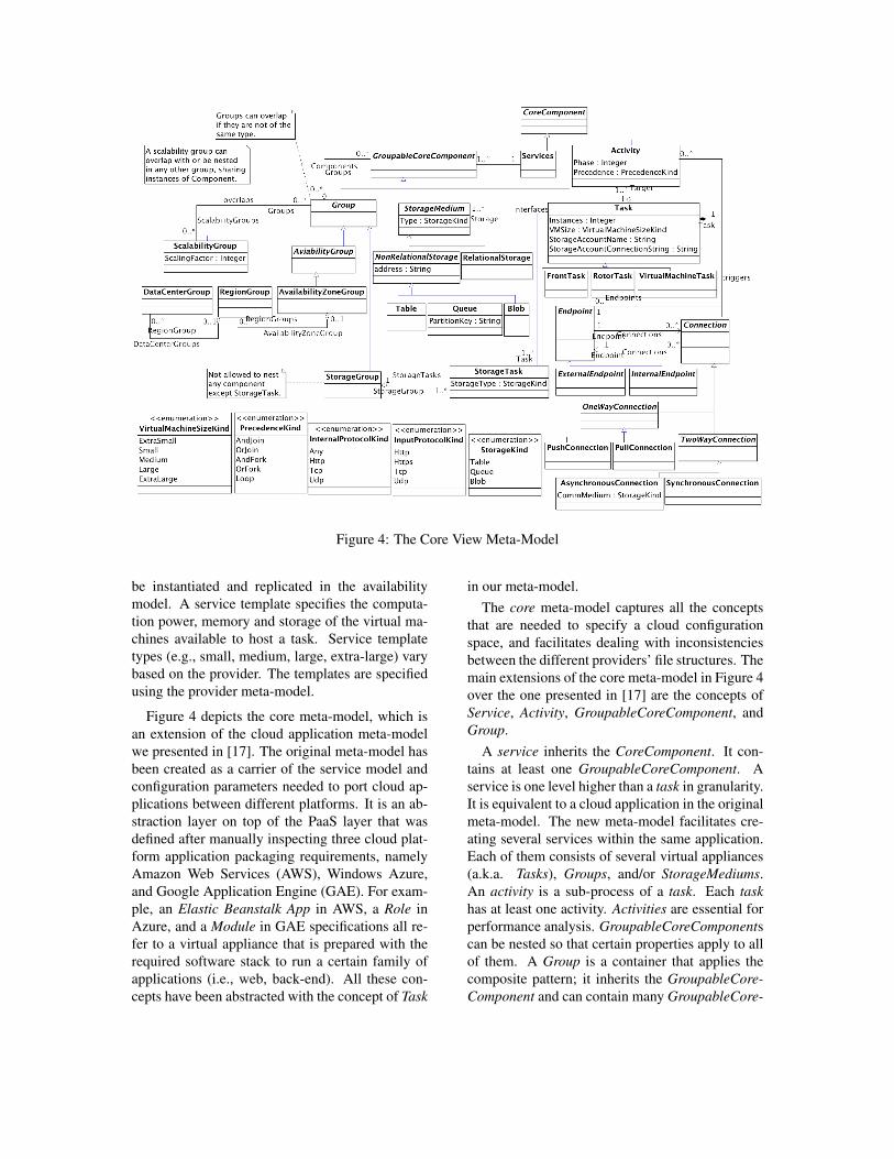
Figure 4: The Core View Meta-Model
be instantiated and replicated in the availabilitymodel. A service template specifies the computa-tion power, memory and storage of the virtual ma-chines available to host a task. Service templatetypes (e.g., small, medium, large, extra-large) varybased on the provider. The templates are specifiedusing the provider meta-model.
Figure 4 depicts the core meta-model, which isan extension of the cloud application meta-modelwe presented in [17]. The original meta-model hasbeen created as a carrier of the service model andconfiguration parameters needed to port cloud ap-plications between different platforms. It is an ab-straction layer on top of the PaaS layer that wasdefined after manually inspecting three cloud plat-form application packaging requirements, namelyAmazon Web Services (AWS), Windows Azure,and Google Application Engine (GAE). For exam-ple, an Elastic Beanstalk App in AWS, a Role inAzure, and a Module in GAE specifications all re-fer to a virtual appliance that is prepared with therequired software stack to run a certain family ofapplications (i.e., web, back-end). All these con-cepts have been abstracted with the concept of Task
in our meta-model.The core meta-model captures all the concepts
that are needed to specify a cloud configurationspace, and facilitates dealing with inconsistenciesbetween the different providers’ file structures. Themain extensions of the core meta-model in Figure 4over the one presented in [17] are the concepts ofService, Activity, GroupableCoreComponent, andGroup.
A service inherits the CoreComponent. It con-tains at least one GroupableCoreComponent. Aservice is one level higher than a task in granularity.It is equivalent to a cloud application in the originalmeta-model. The new meta-model facilitates cre-ating several services within the same application.Each of them consists of several virtual appliances(a.k.a. Tasks), Groups, and/or StorageMediums.An activity is a sub-process of a task. Each taskhas at least one activity. Activities are essential forperformance analysis. GroupableCoreComponentscan be nested so that certain properties apply to allof them. A Group is a container that applies thecomposite pattern; it inherits the GroupableCore-Component and can contain many GroupableCore-

Figure 5: The Performance View Meta-Model
Component elements at once.
The current core meta-model distinguishes threegroup categories: ScalabilityGroup, StorageGroup,and AvailabilityGroup. A ScalabilityGroup canoverlap or be nested in any other group, regulatedby adaptation rules. Components in the same Scal-abilityGroup can be scaled via different Scaling-Factors. A StorageGroup can nest only Storage-Tasks; although it inherits Group, it may not nestany other GroupableCoreComponent. This is en-forced by a validation constraint. Finally, an Avail-abilityGroup nests components, which need to behosted for the same location. It is a superclass forthe three geolocation groups (i.e., Zone, Region,and DataCenter). Availability groups will be dis-cussed in Section 4.5.
4.3 The Performance Meta-ModelFigure 5 depicts the performance meta-model. Itselements were inspired by the UML performanceanalysis modeling profile (PAM), which is part ofMARTE profile [1]. As shown in Figure 5, thereare five association relationships that connect threecore components to corresponding performance as-pects. These links represent integration points be-
tween the cloud resource model and its perfor-mance specifications. Each Activity is linked to Ac-tivityPerformance, Workload, and to itself throughthe Call reflexive relationship. The ActivityPerfor-mance specifies the activity server performance pa-rameters. It specifies that activity’s resource de-mand. The Workload specifies the intensity of de-mand on that activity. The Call component spec-ifies the number of calls that each activity makesto others, the types of these calls, the communi-cation mechanism (InteractionType) used, as wellas the size of the input and output messages as-sociated with the calls. While an activity can bethe source of several calls, each call is associatedwith exactly two activities; a source and a targetactivity. An InteractionType can be synchronous,asynchronous, or forward, with the same semanticsas in LQN [15]. The Endpoint is connected to aNetwork performance component that specifies theconnection parameters. Finally, each Task is con-nected to a HostingEnvironment. The HostingEn-vironment parameters can be inferred based on thetask type and the target PaaS provided as specifiedin the provider meta-model.
In a nutshell, each task can perform several ac-tivities. Each activity has a phase that specifies

the order of execution within the task, and a typethat specifies whether it is normal activity or a join,fork, or loop activity. Phase zero activities are al-ways connected directly to the endpoint, they arethe first activities to receive a request in a task. Anactivity can be linked to other activities within thesame task or with external tasks. Each activity be-longs to one or more workloads. A workload log-ically groups all activities that are affected by thesame traffic class and hence should be executed to-gether, while a task groups all activities that shareand utilize the same underlying resources. Thereare two types of workloads: open workloads, whererequests arrive at a given rate; and closed work-loads, where requests are generated by a fixed num-ber of users (population). Since there is many-to-many relationship between activities and work-loads, another entity is needed to specify the activ-ity execution path for each workload. The work-flow entity is part of the workflow view. Each per-formance solution (PSolution) has a list of work-flows. Each workflow has a designated workloadand an ordered list of the Activities performed bythat workflow. A performance solution (PSolution)also specifies the solution technique used in solvingthe performance model (i.e., analytical, or simula-tion).
4.4 The Adaptation Meta-Model
Figure 6: The Adaptation View Meta-Model
The adaptation meta-model uses rules to con-trol the core. This enables many dynamic featuresof the system, such as elasticity and security, andhelps administrators ensure that the system con-
tinuously satisfies operational requirements (e.g.,minimum operational cost, high performance, andhigh availability). A rule can control the numberof virtual appliance instances, or enable a securityguard or policy. A rule uses a set of key perfor-mance indicators as operands. These are usuallycollected though instrumentation and trace summa-rization.
Figure 6 shows the adaptation meta-model. Eachcomponent or group of components is associatedwith a set of actions. The meta-model enables twotypes of actions, predefined and custom actions.While predefined actions are known ahead of time(e.g., scaler actions), custom actions allow assign-ing external processes. An action is triggered basedon a constraint or reactive adaptation rule. A Con-straintRule is a predefined (static) constraint, suchas the min/max number of instances allowed at acertain time. A ReactiveRule is dynamic, based onevaluating runtime environment parameters againsta set of key performance indicators (e.g., CPU uti-lization, queue length, response time).
4.5 The Availability Meta-Model
Figure 7: The Availability View Meta-Model
Figure 7 shows the availability meta-model. Anavailability zone refers to the distinct physical lo-cation of the available hosting data-centers of aprovider. An AvailabilityZoneGroup nests compo-nents that need to be hosted in the same availabilityzone. It contains several RegionGroups that varybased on the provider. A RegionGroup nests com-ponents that need to be hosted in the same regionand contains many DataCenterGroups. Lastly, a

Table 1: Availability and Fault Recovery Levels
Specified Requirements (Core) Validation Constraint to be Checked
Availability Fault Recovery Very Low N/A A task has one instance Low Fast A task has two instances in the same region Medium Average A task has two instances distributed into two different regions High Slow A task has two instances distributed into two availability-‐zones High Fast A task has three instances, two in the same region, and one in a
different availability-‐zone Very High Fast A task has four instances, two in the same region, one in different
region but same zone, and one in different availability zone
DataCenterGroup nests components that need tobe hosted in the same datacenter. Selecting a spe-cific datacenter for an application is still not sup-ported by most providers.
For each task in the core model, the availabil-ity meta-model allows administrators to specifythe number of instances (TaskInstance) to instan-tiate (replication) and their distribution to differ-ent geolocations (AvailabilityGroups). Recall thatin the core model a service developer specifies aprovider for each task, and the required availabilityand fault recovery levels. The availability modelassigns one of that provider’s available geoloca-tions for each task. This enables hybrid cloud de-ployments, where an application can span multi-ple providers. Once the administrator creates theavailability model, and before the actual artifactsrequired for packaging and deploying the applica-tion on a target platform are generated, a set of con-straint rules are validated to ensure that the avail-ability model conforms with requirements. Table 1shows a list of availability and fault recovery objec-tives, and their corresponding validity constraints.
4.6 The Workflow Meta-ModelTo represent system behaviour and enable opera-tional analysis, the (5+1) model adopts a simpleworkflow meta-model. It specifies activity controlstructures that need to be executed in sequence toperform a certain work. As shown in Figure 8, thetwo main components in the workflow meta-modelare activities and activity incidents. A workflowmodel represents the actual occurrence of the ac-tivities that are defined in the core model alongwith the workload generator (from the performancemodel) that is responsible for the activity enact-
Figure 8: The Workflow View Meta-Model
ment. Each activity incident belongs to one activ-ity. This allows us to compose different workflows(execution scenarios) for the activities according totheir runtime execution.
An activity can be classified as a normal, com-posite or control activity. A control activity linkssource and target activities and describes their ex-ecution sequence and concurrency. Depending onthe control activity type, it can link one source toone target (sequence), one source to many targets(fork), or many sources (join). Activities that suc-ceed a fork control can all be executed concurrently(and fork), or one at a time based on evaluating aboolean (or fork). Similarly, in an (and join) allpredecessor activities must be executed before thejoin, while in an (or join) the execution of any ofthe predecessor activities is enough to start execu-tion of the join activity. The normal activity is anelementary activity that cannot be further decom-

posed, while a composite activity contains (n) nor-mal or complex activities and their control joint ac-tivities.
Even though the workflow model is essential forperformance analysis, it is better to model activ-ity definitions, performance specifications and ac-tual usage scenarios seperately. This separationof concerns maximizes modeling flexibility, fostersreuse, and facilitates modeling of the application’sbehaviour at runtime.
4.7 The Provider Meta-Model
Figure 9: The Provider View Meta-Model
Traditional software architectural approachespresumes that an application will be developedfor one organization, deployed on premises, andmaintained locally. In the public cloud, we de-velop for a multi-organizational systems of sys-tems. The Provider meta-model aims to modeldifferent providers’ templates, offers and costs.Figure 9 depicts the Provider meta-model. Eachprovider provides a list of availability zones, andservice templates. Availability zones represent thephysical locations of provider data-centers, whileservice templates capture different resource speci-fication bundles (i.e., CPU speed, number of cores,memory size, disk space) that serve as templatesfor service tasks. The ability to specify resourcesusing predefined templates is a turning point in au-tomating performance analysis. This meta-modelenables reusability at the resource model level, pro-viding ready to use templates that represent ac-tual cloud provider templates. Each template hasa price that captures how much the resource con-figurations cost per bundle. These prices usuallydepend on a provider’s pricing models, contract pe-riod and terms (e.g., free, weekly, pay-as-you-go).
5 StratusMLWe validated the feasibility of our approach us-ing StratusML [19]. StratusML is a cloud applica-tion modeling language that realizes the (5+1) viewmodel. It enables developers to design high qual-ity, distributed, component-based applications tai-lored for cloud deployment. StratusML permits thelayering of views, letting stakeholders view mod-els from their perspective. Each meta-model inthe (5+1) view model is dedicated a layer in Stra-tusML. Layers can be turned on/off at any time.This lets stakeholders toggle between partial andholistic views, which makes complex models eas-ier to use. StratusML visually models adaptationrules and constraints. It automates the generationof corresponding artifacts for the target cloud fab-ric, using elegant template-driven transformationsto generate complete platform specific artifacts. Afull list of the capabilities of StratusML is beyondthe scope of this paper. However, a recorded demois publicly available [19]. Here, we summarizethe StratusML framework, and examine it againstthe motivating example presented in Section 2 todemonstrate its usefulness in modeling cloud ap-plication requirements.
5.1 The StratusML Framework Ar-chitecture
Figure 10 shows the StratusML framework archi-tecture. It is a model-view-controller frameworkthat transforms, reconciles and adapts models.Transformation, validation, and analysis are per-formed whenever models are updated to keep themconsistent. Both the validator and editor/vieweruse the Stratus meta-model, which realizes the(5+1) meta-models in the Microsoft DSL defini-tion language [11]. Figure 10 shows each (5+1)meta-models in its own layer, viewable in the mod-eling IDE. StratusML supports two transformationtypes: a model transformation that refines PlatformIndependent Models into Provider Specific Models;and template-based transformation that generatesPlatform Specific Models for target platforms. Fig-ure 10 shows the transformation engine using thevalidated StratusML model, and applying templatetransformation on it to generate a target model. Themodel encapsulates essential data about the enti-ties it must generate, while the template dictates thesyntax of the target model. The last component inthe framework is the architecture-aware adaptation

Model Editor/Viewer
Model Controller
Template-Based Transformation
ModelValidation
ModelAnalyzer
Target PSM
Stratus Meta-Model
Domain Constraints
Workflow Architecture
T
Provider Model
Performance Model
Adaptation Model
Core Service Model
Deployment Configuration Model
Cloud Application ModelsPlatform Independent Level
Availability Model
Performance/Availability/Cost
Custom Provider Model
Platform Specific Model
Platform Independent Model
Provider Model + Platform Independent
Provider Specific Model
T TransformationTemplate
Process Operation Data Flow Control Flow
Meta-Model
Architecture-Aware Adaptation Manager
Update (redeploy, reconfigure) Update (reconfigure, reorganize, recompose)
MonitorExecute
Manager
Provider
Admin QA
Developer
Admin
Stakeholder
Figure 10: The Architecture of the StratusML Framework
manager, which deploys the generated models tothe target platform, and monitors the application’sbehaviour after deployment to reflect changes inconfiguration and design. The adaptation man-ager uses the auto-generated rules to manage theapplication at runtime. It completes the applica-tion management process (i.e., Design, Plan, Pack-age, Deploy, Run, Tune, Re-plan/Re-design). Adetailed description of model validation, transfor-mation and the architecture-aware adaptation havebeen omitted due to space limits. StratusML wasbuilt as an extension of Microsoft Visual Studio2012. It utilizes the Microsoft DSL for model def-initions and uses the Text Template Transforma-tion Toolkit (T4) to turn models into desired outputfiles [11]. StratusML lets stakeholders build mod-els, and create (or use ready made) transformationtemplates.
5.2 Meeting CoupoNet Team Require-ments
We used StratusML to model the CoupoNet appli-cation described in Section 2, generating the arti-facts required to: (i) deploy the application to mul-tiple providers, (ii) manage the application, and(iii) analyze its performance. This involved threeweb tasks and two worker tasks. Each web task
was a frontend web MVC-style application thatwas accessed by specific user groups (i.e., CouponProviders, Coupon Buyers, Admins and MarketingResearchers). The first worker task was the appli-cation backend that handles all operations (logictier). The second was the analytics/data-crunchingengine, which processed buy/sell data. There wasalso a storage tier, which consisted of blobs forstoring data collected from buy/sell dumps, andqueues for asynchronous communication betweenworker and web tasks. We do not provide a step-by-step design of this project using StratusML inthis paper (a StratusML usage scenario has beenmade available on the StratusML webpage); in-stead, we highlight how the different layers andfeatures of StratusML can foster collaboration be-tween stakeholders to facilitate creating and ana-lyzing cloud projects. Table 2 lists the requirementsof the CoupoNet stakeholders, extracted from theexample, and the StratusML layer that can be usedto address the stakeholders needs. The followingdiscussion explains how the features provided inthe different layer(s) address stakeholders require-ments.
Core Layer: The core layer furnishes variousgroups (i.e., storage, availability, and scalability)that assist in modeling multi-tenancy (R1) usingdifferent service/data partitioning strategies. Log-

Table 2: Stakeholder Requirements Matched to Corresponding Views in StratusML.
CoupoNet Stakeholder Requirements Stakeholder (5+1) View / StratusML Layer
R1. Model Multi-tenant applications. Service Developer Core
R2. Model Multi-tier applications. Service Developer Core
R3. Communicate architectural decisions to administrators. Service Developer Core + Availability
R4. Estimate the number of instances required. Administrator / QA Performance + Workflow
R5. Uncertainty about the required resources. Administrator Adaptation
R6. Service distribution into multi geographic locations. Administrator Availability
R7. Evaluate different provider offerings. Manager Provider
R8. Migrate between different providers. Administrator/Manager Provider
R9. Minimize administration and configuration tasks. Administrator/Manager All
R10. Manage model co-evolution. Administrator All
ical (i.e., storage, scalability) and physical (i.e.,availability) partitioning can be used to achieve iso-lation between the tenants to ensure privacy, man-age service access privileges, and scale the applica-tion components together. Each StorageMedium orTask in the core model can be configured accordingto one the following multi-tenancy models: SingleInstance Multi Tenant (SIMT), Multi Instance Sin-gle Tenant (MIST) and Multi Instance Multi Tenant(MIMT). The core meta-model also provides plat-form independent task-templates that can be usedfor modeling frontend, backend and storage pro-cesses along with the connections needed to de-scribe interactions between tasks. This facilitatesmodeling multi-tier applications (R2). Plus sincegroups can overlap, grouped components can mi-grate and scale together. Using groups, architectscan ensure their decisions (e.g., reducing coupling,increasing cohesiveness) are preserved (R3), andnot carelessly overridden.
Performance and Workflow Layers: Estimat-ing system performance requires both performanceand workflow layers. StratusML provides per-formance components to specify the informationcollected through monitoring. Figure 11 showsa screenshot of the performance information thatcan be specified for task activities. Once allthe required perfromance information are specifiedtransformation templates can be used to generatea traget performance model. The example in Stra-tusML web page shows how templates can be usedto generate performance models from the specifiedperformance model information for various perfor-mance analysis tools. Currently StratusML sup-ports generating LQN models [15], which can beused to estimate the number of instances required(R4). A detailed example for generating perfor-
Figure 11: StratusML Activity Performance Ex-cerpt
mance models and using them to scale the appli-cation is out of the scope of this paper and will beaddressed in future work.
Adaptation Layer: Using the adaptation layer,StratusML facilitates modeling adaptation rulesand actions, with a focus on scalability actions. Auser can specify constraints and reactive rules, andassociate them with a task or scaling group. Theframework generates the rule-based configurationsrequired to automate resource provisioning. Thissolves the problem when required resources cannotbe estimated at the beginning of the project (R5).Figure 12 shows a screenshot of a task that is as-sociated with an adaptation action that is activatedbased on a default constraint rule.
Availability Layer: The availability layer pro-vides groups that makes it easier to manage the lo-cations and counts of task instances. This helpsadministrators model cloud service distribution tomulti-geographic locations (R6). Figure 13 showsan example of three tasks located in the same data

Figure 12: StratusML Adaptation Rule and ActionExcerpt
center. Each of them has only one instance asshown from the link cardinality. An administratorcan easily instruct the cloud fabric to relocate theinstance into a different location within the sameprovider or even a different provider by changingthe instance properties.
Figure 13: StratusML Availability View Excerpt
Provider Layer: This layer captures providerspecifications. Users can import a supportedprovider’s specifications, or create a custom one.Once imported, an admin can specify a designatedprovider for each availability group, and then dis-tribute task instances to different groups. To eval-uate different provider offerings (R7) the adminis-trator or financial manager can select the availabil-ity groups where instances are distributed, changethem all for a specific provider, or allow hybrid set-tings. The pricing algorithm will loop on all in-stances and use the pricing profile of each instance,reading off the instance size and the provider, tocalculate the total cost of the configuration. Bymodeling service structure and configuration inde-
Figure 14: StratusML Provider and Pricing ProfileExcerpt
pendent of platform, and refining models for targetplatforms, StratusML lets applications migrate be-tween different providers (R8). StratusML makesthis easy via transformation templates customizedby platform, to auto-generate target platform arti-facts. This reduces admin and configuration (R9),and facilitates model co-evolution (R10).
Figure 14 is a snapshot that shows how platformspecifications and pricing information can be spec-ified for different providers (i.e., Windows Azure).
6 Related WorkOur work has taken shape in the context of a richliterature focused on viewpoint architecture frame-works, model-driven quality prediction, and cloudDSMLs .Viewpoint Architectural Frameworks: Usingmultiple views to explore systems from differentangles is common practice in software engineering[13, 23, 25, 34]. There are many such frameworksused in software development. Krutchen [25] fa-mously proposed four views: logical, development,process and physical; plus “use cases” as the fifthview, to completely describe the system lifecycle.Zou and Pavlovski [36] extended the (4+1) viewmodel by adding a control case view to addressnon-functional system requirements. Most such ar-chitectural frameworks are generic enough to de-scribe large class of systems. However, they onlyconsider the dynamism and variability of the designmodels and assume a static deployment infrastruc-ture. Even when deployment models are consid-ered, they are considered as part of the lifecycleand not a driver of architectural evolution.
The (5+1) model was inspired by the (4+1)model process view [25]. In fact, if tasks are con-sidered processes, the (5+1) model can be seen asan extension of the process view, distinguished by

its focus on the cloud application ecosystem (rep-resented by variable deployment models, dynamicinfrastructure, and standardized service offerings).The (5+1) model augments its core with elementsthat enable quality prediction. Its views are limitedbut expressive enough to cover operational require-ments and the application lifecycles in the cloud.Model-Driven Quality Predication (MDQP):Several MDQP approaches appear in the literature.Many were surveyed in [12, 22, 24]. Accordingto Koziolek’s [24] classification, the main threecategories for MDQP approaches are predictionbased on: (i) UML (e.g., CB-SPE [5], SPT [28],MARTE [1]) (ii) proprietary meta-models (e.g.,CBML [33], KLAPER [10], ROBOCOP [7], PAL-LADIO [4]), and (iii) middle-ware (e.g., NICTA[26]). Our approach relies on a proprietary meta-model. MDQP frameworks can be differentiatedby (i) the non-functional properties they model, and(ii) their accurate depiction of both software and re-source models. Most focus on performance analy-sis and software modeling. Some frameworks thatsupport non-functional properties and enable hard-ware and software modeling include MARTE [1],and Descartes (DML) [8]. Like Descartes, wemodel dynamic systems on dynamic infrastructure,but we differ from both MARTE and Descartes bybeing cloud specific. Both generic and specificframeworks have pros and cons [9]. For exam-ple, while both we and Descartes model adapta-tion requirements and actions, Descartes’ genericmethod models multiple strategies. In compari-son, we currently only model rule-based adapta-tion. However, since most cloud providers supportrule-based adaptation and provide rule engines, ourframework does generate the actual artifacts (rulefiles) needed to control applications at runtime.Descartes requires framework-specific strategies,which can complicate automation and model trans-formation.Runtime Models: The problem described in thispaper is also related to managing and configuringsoftware systems at runtime [6]. Using runtimemodels to manage software systems is not new.Several approaches have been developed to addressthis problem [14, 29]. Recently, Zhang et al. lever-aged runtime models for the management of di-verse cloud resources [35]. Other than being clouddomain specific, our approach distinguishes itselfin the way it weaves the different models togetherwith the service model, and its ability to provide
partial and holistic views to describe and analyzethe cloud systems from different perspectives.Cloud DSML: There have been several recent pro-posals for using MDE to develop cloud DSMLs[2, 27]. MODAClouds [3], and CloudML [16]are most related to our approach. Methods canbe differentiated based on the features they pro-vide. What distinguishes StratusML from otherlanguages is its ability to provide partial and holis-tic views of the different cloud application con-cerns using layers, its ability to visually modeladaptation rules and actions, and its ability to dealwith platform heterogeneity using template-basedtransformations.
7 ConclusionsWe presented a new (5+1) architectural view modelfor cloud applications. It was realized as a cloudDSML, StratusML, using layers to enable both par-tial and holistic views. The model promotes flexi-bility, portability, reusability and productivity. Weshowed how StratusML supports cloud stakeholdercollaboration. The (5+1) model was designed forthe cloud domain, but it applies to any large dis-tributed system where software evolves in a dy-namic environment.
The original contributions of this research are:(i) a new cloud specific architecture view modeltaking service models as first class entities, andbuilding views that address cloud application evo-lution at runtime; (ii) naming the “Malleable Ap-plication Architectural Style”, commonly used incloud computing, to facilitate managing cloud con-figuration spaces and promote architectural self-awareness; (iii) addressing the main service oper-ational attributes needed to architect high qualitycloud applications using proprietary meta-modelsthat augment the cloud core service/resource modelwith quality-related concepts and attributes; and(iv) realizing the (5+1) view model as a cloudDSML, using layers to enable toggling betweenpartial and holistic views, facilitating dynamic be-haviour modeling using adaptation rules and ac-tions, and “weaving” stakeholder concerns togetherto generate useful artifacts.
Future research directions include extending thescenario presented here to (i) showcase other fea-tures of StratusML, (ii) show how the models pre-sented here can be used for performance prediction,software adaptation, availability maximization and

cost minimization, and (iii) to present concrete ex-amples for model transformation and platform spe-cific artifact generation.
References[1] The Object Management Group. UML
Profile for MARTE: Modeling and anal-ysis of real-time embedded systems,Version 1.1. OMG Document Number:formal/2011-06-02 [Online]. Available:http://www.omg.org/spec/MARTE/1.1,(2011).
[2] M. Almorsy, J. Grundy, and A. Ibrahim.Adaptable, model-driven security engineeringfor SaaS cloud-based applications. AutomatedSoftware Engineering, Springer, 1-38 (2013).
[3] D. Ardagna, E. Di Nitto, P. Mohagheghi, et al.Modaclouds: A model-driven approach for thedesign and execution of applications on multi-ple clouds. In: ICSE Workshop on Modelingin Software Engineering, pp. 50-56. (2012).
[4] S. Becker, H. Koziolek, and R. Reussner. ThePalladio component model for model-drivenperformance prediction. Journal of Systemsand Software, 82(1): 3-22 (2009).
[5] A. Bertolino and R. Mirandola. CB-SPE Tool: Putting component-based perfor-mance engineering into practice In: Crnkovic,I., Stafford, J., Schmidt, H., Wallnau, K.(eds.) Component-Based Software Engineer-ing. LCNS, vol. 3054, pp. 233-248. Springer,Heidelberg (2004).
[6] G. Blair, N. Bencomo, and R. B. France. Mod-els@ run.time. Computer, 42(10): 22-27(2009).
[7] E. Bondarev, J. Muskens, M. Chaudron,J. Lukkien, et al. Predicting real-time prop-erties of component assemblies: A scenario-simulation approach. In: Euromicro Confer-ence, pp. 40-47 (2004).
[8] F. Brosig, N. Huber, and S. Kounev.Architecture-level software performanceabstractions for online performance predic-tion. Science of Computer Programming, 1-22(2013).
[9] W. Chehade, A. Radermacher, F. Terrier,B. Selic, ans Se. Gerard. A model-drivenframework for the development of portablereal-time embedded systems. In: the Interna-tional Conference on Engineering of ComplexComputer Systems, pp. 45-54. (2011).
[10] A. Ciancone, A. Filieri, M. L. Drago, R. Mi-randola, and V. Grassi. KlaperSuite: An inte-grated model-driven environment for reliabil-ity and performance analysis of component-based systems, In: Bishop, J., Vallecillo, A.(eds.) Objects, Models, Components, Patterns.LCNS, vol. 6705, pp. 99-114. Springer, Hei-delberg (2011).
[11] S. Cook, C. Jones, S. Kent, and A.C. Wills.Domain-specific development with Visual Stu-dio DSL tools. Addison-Wesley Professional(2007).
[12] V. Cortellessa, A. Di Marco, and P. Inver-ardi. Model-based software performance anal-ysis. Springer (2011).
[13] Department of Defense Architecture Frame-work Working Group et al. DoD architectureframework, Version 1.5. Department of De-fense, USA, (2007).
[14] R. France and B. Rumpe. Model-Driven De-velopment of Complex Software: A researchroadmap. In: Future of Software Engineering,pp. 37-54. (2007).
[15] G. Franks, T. Al-Omari, M. Woodside,O. Das, and S. Derisavi. Enhanced Modelingand Solution of Layered Queueing Networks.IEEE Transactions on Software Engineering,35(2): 148-161 (2009).
[16] G. Goncalves, P. Endo, M. Santos, D. Sadok,et al. CloudML: An integrated language forresource, service and request description ford-clouds. In: the International Conferenceon Cloud Computing Technology and Science,pp. 399-406. (2011).
[17] M. Hamdaqa, T. Livogiannis, and L. Tahvil-dari. A reference model for developing cloudapplications. In: the International Conferenceon Cloud Computing and Services Science, pp.98-103. (2011)

[18] M. Hamdaqa, and L. Tahvildari. Cloud com-puting uncovered: A research landscape. Ad-vances in Computers, (86): 41-85 (2011).
[19] M. Hamdaqa and L. Tahvildari. StratusML:A layered cloud applications modeling lan-guage. Demo Video, [Online]. Available:http://www.stargroup.uwaterloo.ca/˜mhamdaqa/stratusml, (2013).
[20] J. D. Herbsleb. Global software engineering:The future of socio-technical coordination. In:Future of Software Engineering, pp. 188-198.(2007).
[21] P. Horn. Autonomic Computing: IBM’sPerspective on the State of Information Tech-nology. IBM Computing Systems, (15): 1-40(2001).
[22] M. Isa, M. Z. Zaki, and D. N. Jawawi. ASurvey of Design Model for Quality Analy-sis: From a performance and reliability per-spective. Computer and Information Science,6(2): 55-70 (2013).
[23] A. C. Klug and D. Tsichritzis. Multiple viewsupport within the ansi/sparc framework. In:the International Conference on Very LargeData Bases, vol. 3, pp. 477-488. (1977).
[24] H. Koziolek. Performance evaluation ofcomponent-based software systems: A sur-vey. Performance Evaluation, 67(8): 634–658(2010).
[25] P. B. Kruchten. The 4+1 view model of archi-tecture. IEEE Software, 12(6): 42-50 (1995).
[26] Y. Liu, I. Gorton, and A. Fekete. Design-level performance prediction of component-based applications. IEEE Transactions on Soft-ware Engineering, 31(11): 928-941 (2005).
[27] D. Petcu, B. Di Martino, S. Venticinque, et al.Experiences in building a mosaic of clouds.Journal of Cloud Computing: Advances, Sys-tems and Applications, 2(1): 1-22 (2013).
[28] B. Selic, A. Moore, M. Woodside, B. Wat-son, M. Bjorkander, M. Gerhardt, andD. Petriu. UML profile for schedulabil-ity, performance and time. OMG doc-ument, Version 1.1, [Online]. Available:http://www.omg.org/spec/SPTP/1.1, (2005).
[29] H. Song, Y. Xiong, F. Chauvel, G. Huang,Z. Hu, and H. Mei. Generating synchroniza-tion engines between running systems and theirmodel-based views. In: Model-Driven Engi-neering Languages and Systems, pp. 140-154.(2010).
[30] C. Szyperski, J. Bosch, and W. Weck.Component-oriented programming. In: the Eu-ropean Conference on Object-Oriented Tech-nology, pp. 795-795. (1999).
[31] R. N. Taylor, N. Medvidovic, and P. Oreizy.Architectural styles for runtime software adap-tation. In: Joint Working IEEE/IFIP Con-ference on Software Architecture & EuropeanConference on Software Architecture, pp. 171-180. (2009).
[32] P. Vitharana, H. Jain, and F. Zahedi. Strategy-based design of reusable business components.IEEE Transactions on Systems, Man, and Cy-bernetics, Part C: Applications and Reviews,34(4):460-474 (2004).
[33] X. Wu and M. Woodside. Performancemodeling from software components. ACMSIGSOFT Software Engineering Notes, 29(1):290-301 (2004).
[34] J. A. Zachman. A framework for informa-tion systems architecture. IBM Systems Jour-nal, 26(3):276-292 (1987).
[35] X. Zhang, X. Chen, Y. Zhang, Y. Wu, W. Yao,G. Huang, and Q. Lin. Runtime modelbased management of diverse cloud resources.In: Model-Driven Engineering Languages andSystems, pp. 572-588. (2013).
[36] J. Zou and C. J. Pavlovski. Modeling archi-tectural non functional requirements: from usecase to control case. In: the International Con-ference on e-Business Engineering, pp. 315-322. (2006).