Embed Size (px)
Citation preview

The 4th EIC workshop May 19-23, 2008
Experience with Crab cavities
The 4th Electron Ion Collider Workshop
19-23 May, 2008
Hampton University
Mika Masuzawa, KEK

The 4th EIC workshop May 19-23, 2008
Contents
1. Introduction• Where/What is KEKB?• Characteristics of KEKB
2. Machine performance before Crab cavities• Luminosity history• Machine parameters
3. Machine performance with Crab cavities• Crab crossing scheme• Cavity production & installation• Beam commissioning with crab cavities
• Can we confirm the prediction?
4. Summary

The 4th EIC workshop May 19-23, 2008
1. Introduction
• Where/What is KEKB?• Characteristics of KEKB
Mt. TsukubaNikko
KEKB tunnel ~11 m below Ground Level
Belle @IP
Linac
Aerial view of KEK
TokyoMt.Fuji
About KEKB
Where

The 4th EIC workshop May 19-23, 2008
Superconducting cavities (HER)
e-
e+
ARES cavities (LER)
8 GeV e- 3.5 GeV e+ Linac e+ target
ARES cavities (HER)
IR
Belle detectorKEKB B-FactoryBeam energy
– 8GeV (electron, “HER”)– 3.5GeV (positron, “ LER”)
Circumference– 3016 m– Uses TRISTAN tunnel
RF system
– fRF ~ 509MHz
– ARES (LER)– ARES+SCC (HER)
The construction of KEKB began in 1994,and was completed in November 1998.Commissioning started in Dec.1998.
What is KEKB
About KEKB

The 4th EIC workshop May 19-23, 2008
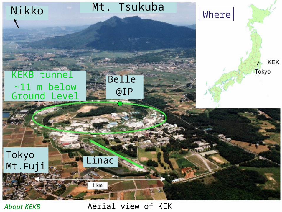
Characteristics of KEKB
The 4th EIC workshop May 19-23, 2008
Superconducting Cavities Storage of high current >1.4 A
ARES normal conducting cavities: Large storage cavity for stable acceleration
Finite crossing angleSuperconducting Q magnet for final focus.Small beam size achieved at IP
2.5 Cell Lattice: Low non-linearityhigh flexibility
J-LINAC: Efficient acceleration in a limited spaceTwo bunch positron injection
Bunch-by-bunch feedback system
Solenoids to reduce electron cloud effects
IR
SCC
Arc sectionmagnets
ARES
Solenoids on vacuum pipe
Characteristics of KEKB
The 4th EIC workshop May 19-23, 2008
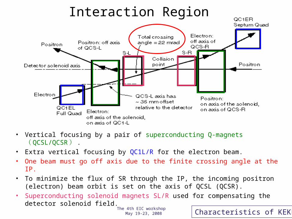
Interaction Region
• Vertical focusing by a pair of superconducting Q-magnets ( QCSL/QCSR ) .
• Extra vertical focusing by QC1L/R for the electron beam.
• One beam must go off axis due to the finite crossing angle at the IP.
• To minimize the flux of SR through the IP, the incoming positron (electron) beam orbit is set on the axis of QCSL (QCSR).
• Superconducting solenoid magnets SL/R used for compensating the detector solenoid field.
Characteristics of KEKB

PEP-II
KEKB
KEKB has 22 mrad horizontal crossing angle at the IP:
•Easier beam separation
•Simpler design around the IP.
•Fewer components.
•Less synchrotron radiation.
•Less luminosity-dependent background.
•Space for compensation solenoid, etc.
More on Interaction Region
Characteristics of KEKB

The 4th EIC workshop May 19-23, 2008
2. Machine performance before Crab cavities
• Luminosity history• Peak luminosity• Integrated luminosity
• Machine parameters (Design & Best)

The 4th EIC workshop May 19-23, 2008
Luminosity history
Peak
Daily
design
Peak luminosity
The 4th EIC workshop May 19-23, 2008
The 4th EIC workshop May 19-23, 2008
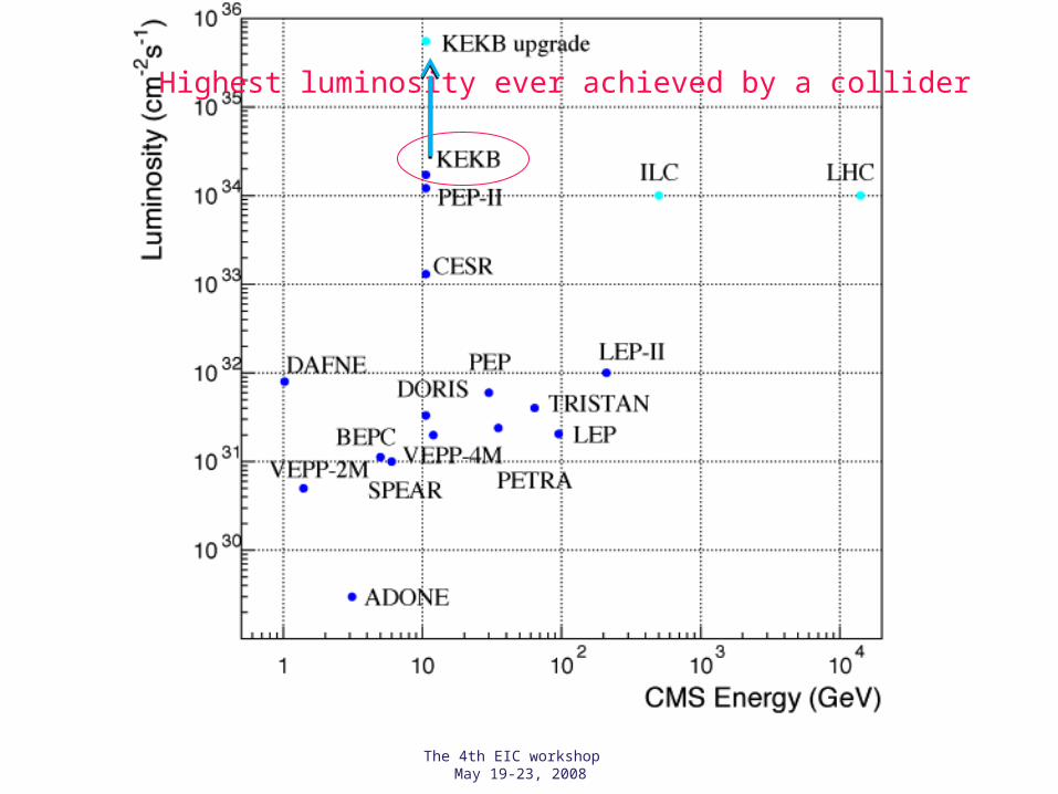
Highest luminosity ever achieved by a collider

The 4th EIC workshop May 19-23, 2008
1034
1033
1032
1031
1030
1029
Pea
k lu
min
osity
(cm
-2 s
-1)
1970 1975 1980 1985 1990 1995 2000 2005 2010 Year

Integrated luminosity
The 4th EIC workshop May 19-23, 2008

The 4th EIC workshop May 19-23, 2008
The best day (1.23 /fb/day) before Crab cavity installation
Design luminosity

The 4th EIC workshop May 19-23, 2008
Continuous injection scheme since 2004

The 4th EIC workshop May 19-23, 2008
Integrated luminosity
The 4th EIC workshop May 19-23, 2008
Machine parameters
The 4th EIC workshop May 19-23, 2008
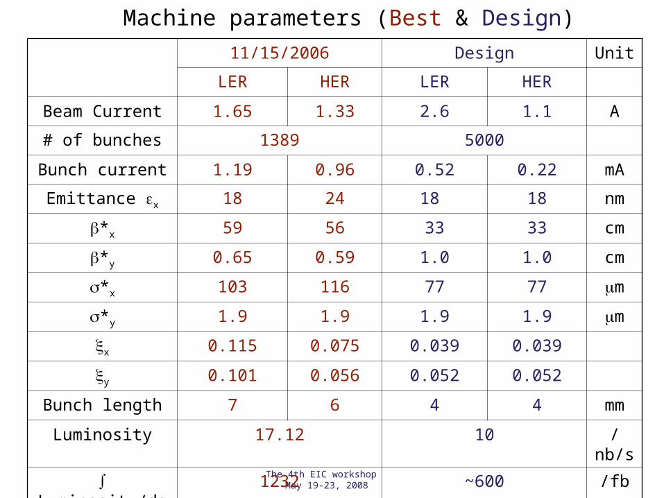
11/15/2006 Design Unit
LER HER LER HER
Beam Current 1.65 1.33 2.6 1.1 A
# of bunches 1389 5000
Bunch current 1.19 0.96 0.52 0.22 mA
Emittance x 18 24 18 18 nm
*x 59 56 33 33 cm
*y 0.65 0.59 1.0 1.0 cm
*x 103 116 77 77 m
*y 1.9 1.9 1.9 1.9 m
x 0.115 0.075 0.039 0.039
y 0.101 0.056 0.052 0.052
Bunch length 7 6 4 4 mm
Luminosity 17.12 10 /nb/s
Luminosity/day 1232 ~600 /fb
Machine parameters (Best & Design)
The 4th EIC workshop May 19-23, 2008
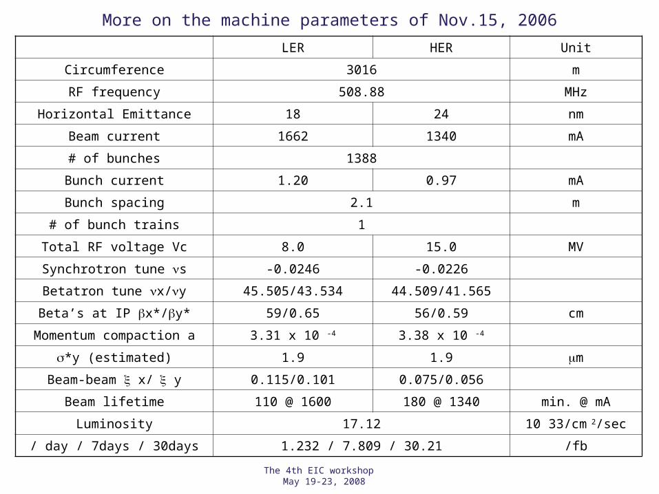
More on the machine parameters of Nov.15, 2006
LER HER Unit
Circumference 3016 m
RF frequency 508.88 MHz
Horizontal Emittance 18 24 nm
Beam current 1662 1340 mA
# of bunches 1388
Bunch current 1.20 0.97 mA
Bunch spacing 2.1 m
# of bunch trains 1
Total RF voltage Vc 8.0 15.0 MV
Synchrotron tune s -0.0246 -0.0226
Betatron tune x/y 45.505/43.534 44.509/41.565
Beta’s at IP x*/y* 59/0.65 56/0.59 cm
Momentum compaction a 3.31 x 10 -4 3.38 x 10 -4
*y (estimated) 1.9 1.9 m
Beam-beam x/ y 0.115/0.101 0.075/0.056
Beam lifetime 110 @ 1600 180 @ 1340 min. @ mA
Luminosity 17.12 10 33/cm 2/sec
/ day / 7days / 30days 1.232 / 7.809 / 30.21 /fb

The 4th EIC workshop May 19-23, 2008
Machine performance Summary before Feb. 2007 (without crab cavities)
• Recorded highest luminosity of 17 /nb/sec (1.7x1034 /cm2/s),
with a crossing angle at the IP.

The 4th EIC workshop May 19-23, 2008
For even higher luminosity
• Achieve a head-on collision while keeping the crossing angle at the IP.Crab Crossing Scheme

The 4th EIC workshop May 19-23, 2008
3. Machine performance with Crab cavities
• What is Crab crossing scheme?• Cavity production and installation• Beam commissioning

What is Crab crossing scheme?
The 4th EIC workshop May 19-23, 2008

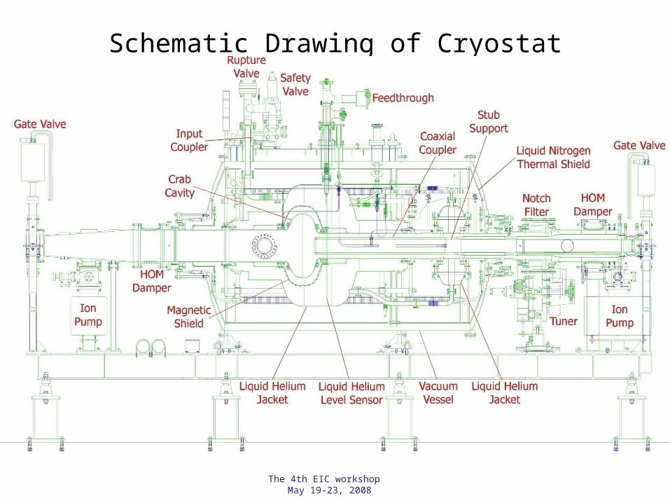
Input Coupler Liq. Helium Vessel
Stub Support
Coaxial Coupler
Copper Bellows80 K Liq. Nitrogen Shield
Notch Filter
RF Absorber
Aluminum End Plate
Aluminum End Plate
SUS Support Pipe
Crab Crossing Scheme
Crossing angle 22 mrad
Head-on (crab)(Strong-strong simulation)
Simulation by K. Ohmi
K. Hosoyama, et al.
RF Deflector( Crab Cavity )
Head-onCollision
Crossing Angle (11 x 2 m rad.)
Electrons PositronsLERHER
1.41 MV
1.41 MV
1.44 MV
1.44 MV
First proposed by R. B. Palmer in 1988 for linear colliders.
Need two RF deflectors for each ring
The 4th EIC workshop May 19-23, 2008
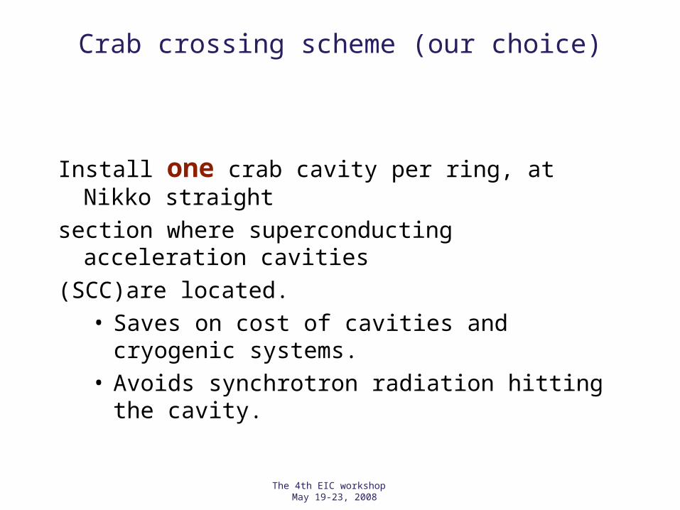
Crab crossing scheme (our choice)
Install one crab cavity per ring, at Nikko straight
section where superconducting acceleration cavities
(SCC)are located.• Saves on cost of cavities and cryogenic systems.• Avoids synchrotron radiation hitting the cavity.

The 4th EIC workshop May 19-23, 2008
Crab crossing scheme Comparison between two cavities/ring
and one cavity/ring
IPIP
beam beam
crabcavity
crabcavity
bunch tailbunch head
crabcavity
1 cavity per ring 2 cavities per ring
orbits of bunch head and tail
Different COD between head and tail Same COD

The 4th EIC workshop May 19-23, 2008
Crab Crossing Scheme (KEKB)
•Beam tilts all around the ring.
•z-dependent horizontal closed orbit.
• tilt at the IP (head on):Crab cavities
Streak cameras to observe the tilt
LER HER
x 22 mrad
*x 80 80 cm
cx 73 162 m
x /2 0.505 0.511
cx/2 ~0.25 ~0.25
Vc 0.95 1.45 MV
rf /2 509 MHz
x2
xcx
*cos xc x 2
2sin x 2
VcrfEc
Typical parameters for Crab crossingTilt angle depends on crab voltage, x *and x(Crab).

The 4th EIC workshop May 19-23, 2008
What crab cavity looks like
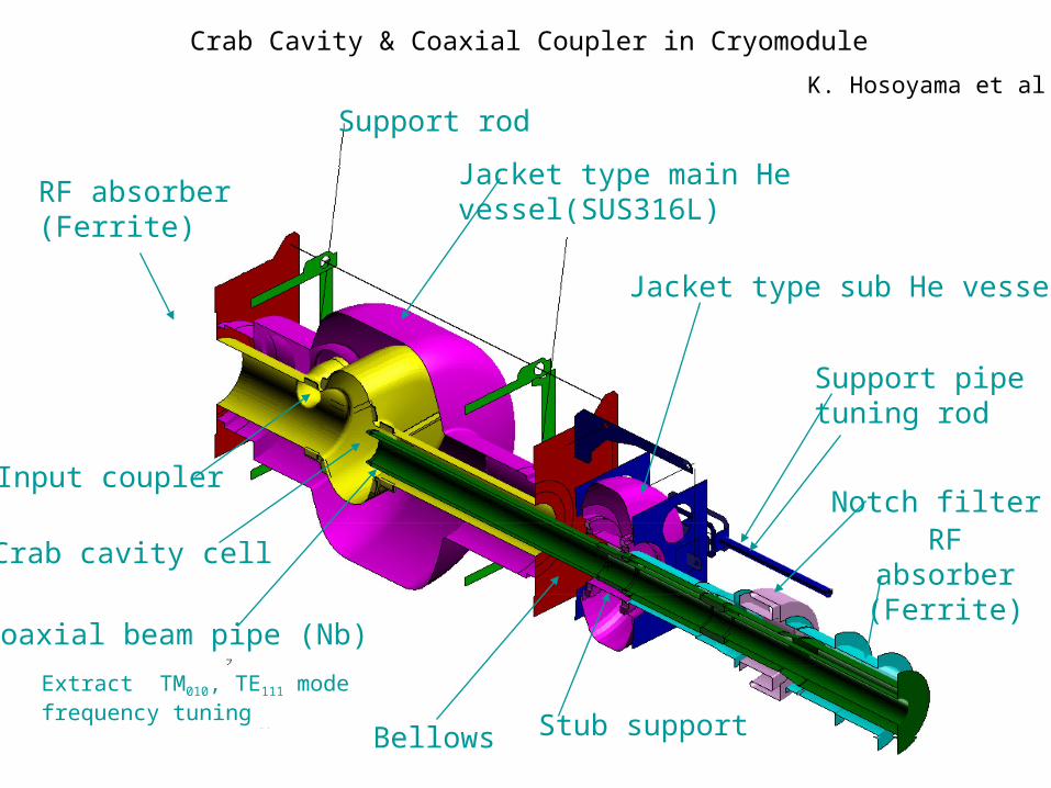
Crab Cavity & Coaxial Coupler in Cryomodule
Support rod
Jacket type main He vessel(SUS316L)
Jacket type sub He vessel
Coaxial beam pipe (Nb)
Stub support
Crab cavity cell
Notch filter
Support pipe tuning rod
RF absorber(Ferrite)
Extract TM010, TE111 modefrequency tuning
Input coupler
Bellows
RF absorber(Ferrite)
K. Hosoyama et al
The 4th EIC workshop May 19-23, 2008
Schematic Drawing of Cryostat

The 4th EIC workshop May 19-23, 2008
Cavity production and installation
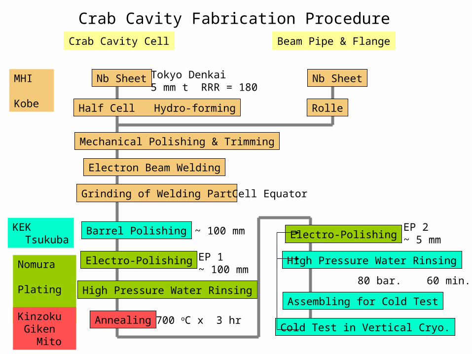
Crab Cavity Fabrication Procedure
Nb Sheet
Half Cell Hydro-forming
Mechanical Polishing & Trimming
Electron Beam Welding
Crab Cavity Cell
Grinding of Welding Part
Barrel Polishing
Electro-Polishing
High Pressure Water Rinsing
Annealing
Electro-Polishing
Beam Pipe & Flange
Nb Sheet
Rolle
High Pressure Water Rinsing
Assembling for Cold Test
Cold Test in Vertical Cryo.
MHI Kobe
KEK Tsukuba
Nomura Plating Kanuma
Kinzoku Giken Mito
Tokyo Denkai5 mm t RRR = 180
Cell Equator
~ 100 mm
EP 1~ 100 mm
EP 2~ 5 mm
700 oC x 3 hr
80 bar. 60 min.

Forming and barrel polishing
Forming of 4 Half-Cells for Crab Cavity for LER and HER Feb. 14, 2005 at Mitsubishi Heavy Industries, LTD. Kobe
Barrel PolishingNov. 11, 2005 at KEK
Polishing Time 312 hours

High Pressure Rinsing and Assembling for RF Cold Test
Nozzle
High pressure water rinsing by 80 bar Ultra-Pure water
Rotation & up-down motion
Set flanges of beam pipes and ports in Class 100 clean room
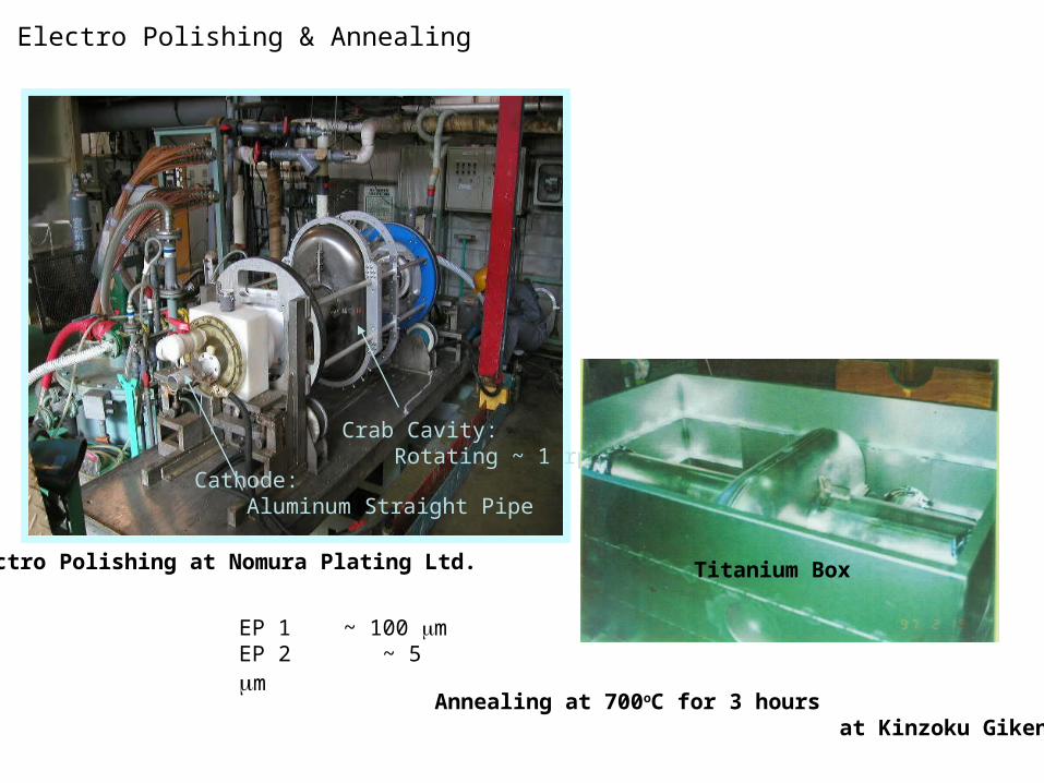
Electro Polishing & Annealing
Cathode: Aluminum Straight Pipe
Crab Cavity: Rotating ~ 1 rpm
Annealing at 700oC for 3 hours at Kinzoku Giken Ltd.
Titanium Box
EP 1 ~ 100 mEP 2 ~ 5 m
Electro Polishing at Nomura Plating Ltd.
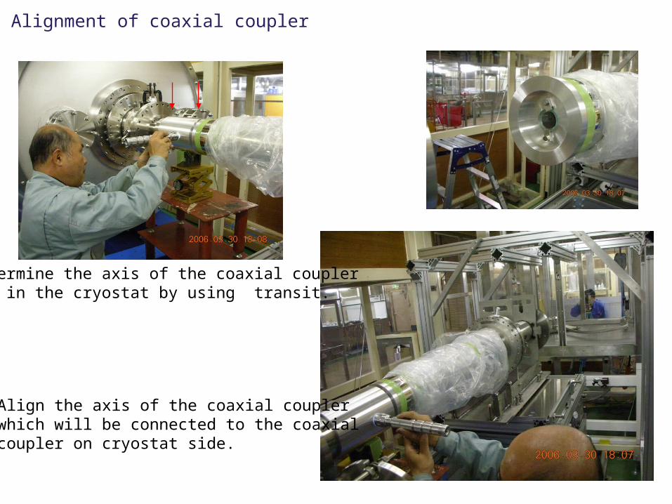
Alignment of coaxial coupler
Determine the axis of the coaxial couplerset in the cryostat by using transit.
Align the axis of the coaxial couplerwhich will be connected to the coaxial coupler on cryostat side.
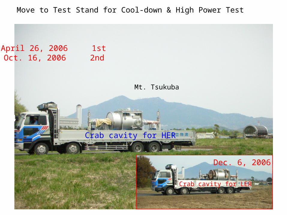
Move to Test Stand for Cool-down & High Power Test
Mt. Tsukuba
Crab cavity for HER
April 26, 2006 1stOct. 16, 2006 2nd
Crab cavity for LER
Dec. 6, 2006
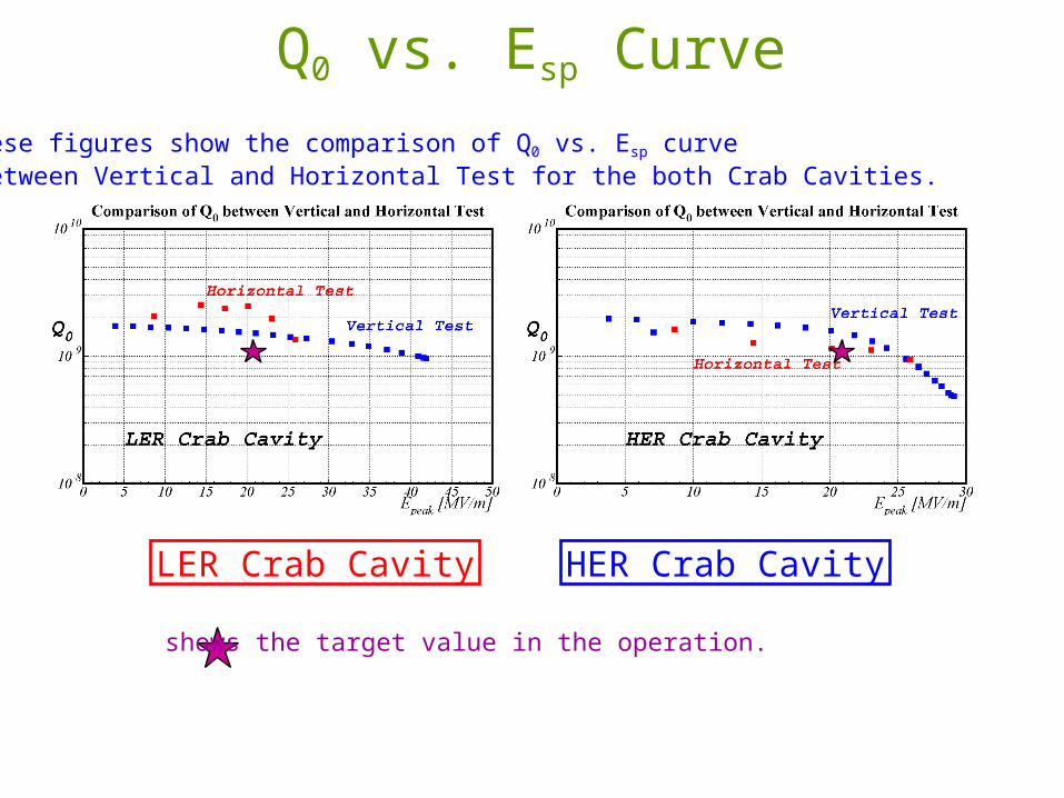
Q0 vs. Esp Curve
LER Crab Cavity HER Crab Cavity
shows the target value in the operation.
These figures show the comparison of Q0 vs. Esp curve between Vertical and Horizontal Test for the both Crab Cavities.


The 4th EIC workshop May 19-23, 2008
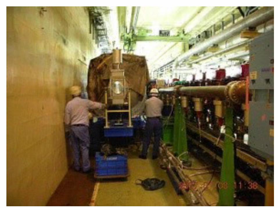
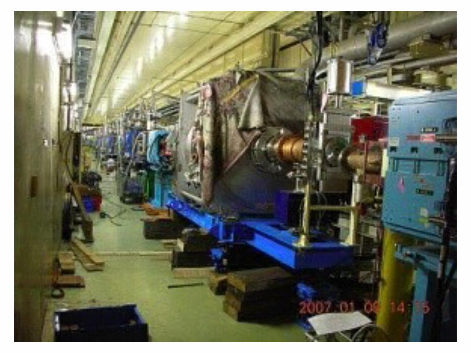
Two crab cavities were installed in KEKB in January 2007.
HER (e-, 8 GeV) LER (e+, 3.5 GeV)
The 4th EIC workshop May 19-23, 2008
Beam commissioning with crab cavities
Be very careful as we have no spare cavities
Will the beam receive the kick that we want?
Can we collide the crabbed beams?
No extra heating due to crabbing in the entire ring?

The 4th EIC workshop May 19-23, 2008
2007.2.13 - 3.19 (first beam operation with Crab cavities)
Collision tuning with crab on
Tuning (SR monitors, streak cameras and so on). Crab cavitiy aging without beams.
Feb. 19 First beam with crab kicks (No collision when Crab on).
Feb. 21 First collision with Crab crossing.

The 4th EIC workshop May 19-23, 2008
Is the beam really crabbed (tilted)?

The 4th EIC workshop May 19-23, 2008
Tilt confirmed!
LER HER
inside of the rings
outside of the rings
Observation with Streak Cameras (H. Ikeda et al, FRPMN035)
The streak camera
longitudinal
horizontal

Crab Phase Scan (LER)
0
36
72108
144
180
216
252288
324
360
Crab voltage Vcrab set was 1.0MV Obtained from the data was 0.987MVAgrees very well.
crabHorizontal orbit by crab kickcrab
Horizontal kick by crab cavity (rad)(Estimated by orbit fit)
The 4th EIC workshop May 19-23, 2008
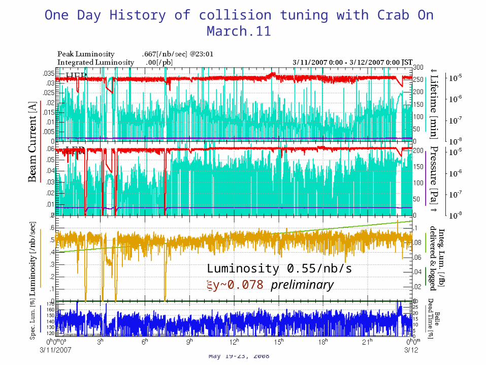
One Day History of collision tuning with Crab On March.11
Luminosity 0.55/nb/s y~0.078 preliminary
The 4th EIC workshop May 19-23, 2008
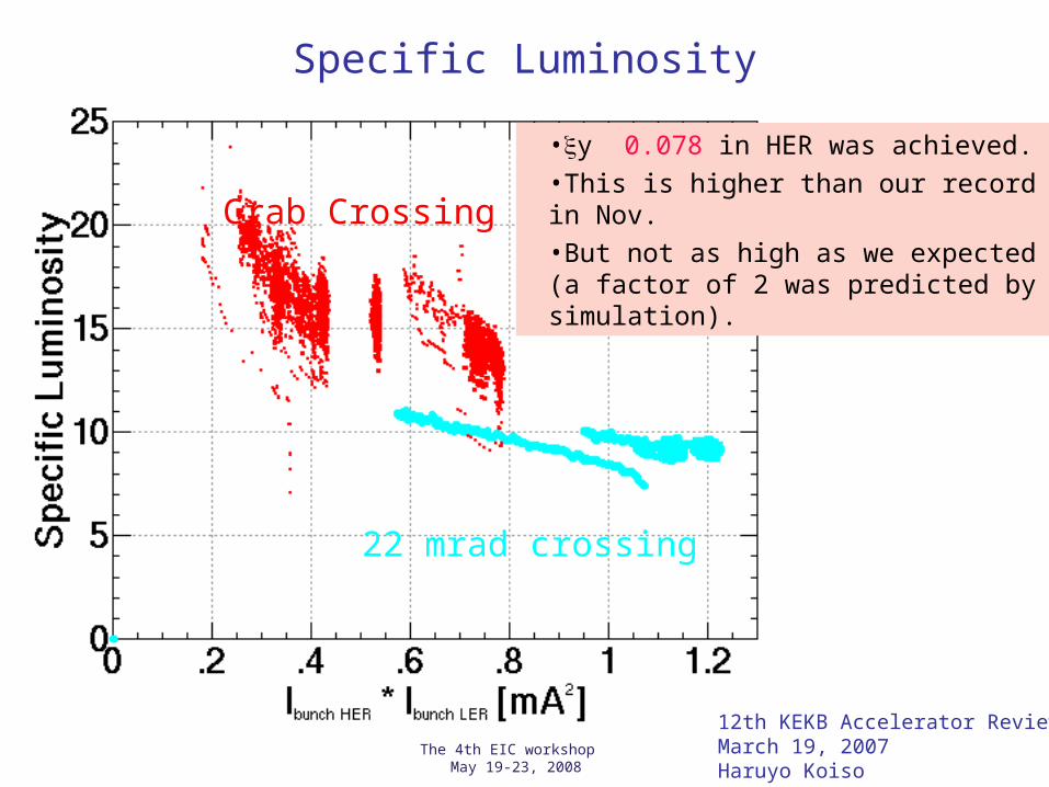
Specific Luminosity
Crab Crossing
22 mrad crossing
•y 0.078 in HER was achieved.
•This is higher than our record in Nov.
•But not as high as we expected (a factor of 2 was predicted by simulation).
12th KEKB Accelerator Review March 19, 2007Haruyo Koiso
The 4th EIC workshop May 19-23, 2008
For higher luminosity!luminosity
specific luminositybeam-beam tune shift
Can we confirm the prediction?
The 4th EIC workshop May 19-23, 2008
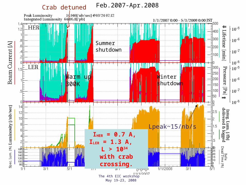
Crab detuned Feb.2007-Apr.2008
Summershutdown
Wintershutdown
Lpeak~15/nb/sIHER = 0.7 A, ILER = 1.3 A,
L > 1034 with crab crossing.
Warm up300K

The 4th EIC workshop May 19-23, 2008
Oct.-Dec. 2007
3.5 3.06 buckets
Peak: 14.7 /nb/s
xcm
We trieddifferent opticsdifferent fill patternHigher HER/LER currents

The 4th EIC workshop May 19-23, 2008

The 4th EIC workshop May 19-23, 2008
Specific luminosity with crab crossing
•Simulation (no Crab)
•Simulation (Crab)
Higher than without Crab,but not as high as prediction.
22 mrad crossing
3.06 bucket spacing
Specific Luminosity
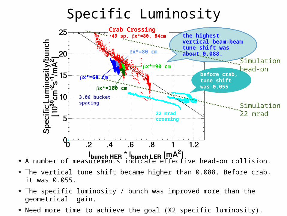
★ A number of measurements indicate effective head-on collision.
★ The vertical tune shift became higher than 0.088. Before crab, it was 0.055.
★ The specific luminosity / bunch was improved more than the geometrical gain.
★ Need more time to achieve the goal (X2 specific luminosity).
the highest vertical beam-beam tune shift was about 0.088.
before crab, tune shift was 0.055
Simulation22 mrad
x*=90 cm
x*=68 cm
x*=80 cm
x*=100 cm
Simulationhead-on
Crab Crossing•49 sp. x*=80, 84cm

The 4th EIC workshop May 19-23, 2008
Specific Luminosity
Crab crossing•49-sp x*=80, 84cmx=18, 24 nm•3.5-sp x*=80cm•3.06-sp x*=80cm•3.06-sp x*=90cm
22 mrad crossing
y=-16.35x+26.54 Green Ratio=100%
Green line
y~0.093 (HER) (4/3)

The 4th EIC workshop May 19-23, 2008
Beam-beam parameter
[mA]
:experiments
Crab crossing
Crossing angle 22mrad

The 4th EIC workshop May 19-23, 2008
Why specific luminosity not doubled?Possibilities
• We can not find a parameter set which gives a higher specific luminosity, even if such a parameter set exists?
– Too large a parameter space?
• Faster parameter search, more efficient method of parameter search
– Short beam lifetime prevents us from reaching a better parameter set?
• Identify the mechanism to determine the beam lifetime
• Implement e- and e+ simultaneous injection ( autumn 2008 )• Some unknown effects are responsible for the low specific luminosity?
– Synchro-betatron resonance?
– Vertical crab?
– Fast noise?
– Bunch-by-bunch orbit difference?
– Lattice non-linearity?
– Global x-y coupling?
– Others?

The 4th EIC workshop May 19-23, 2008
Tuning parameters
22-241-122
16106
42
•Many knobs are determined by scans only on the luminosity, beam sizes,
and the lifetime.
•Scan is slow, each takes about 30 minutes.
•Problem in multi-dimensional nonlinear optimization.
IP Coupling
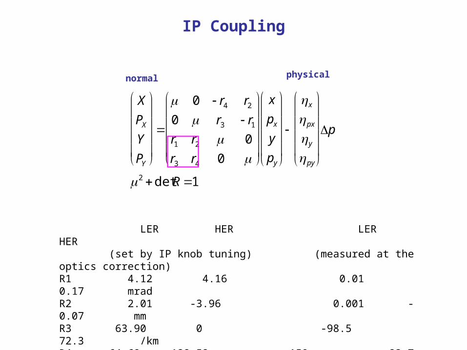
LER HER LER HER (set by IP knob tuning) (measured at the optics correction)R1 4.12 4.16 0.01 0.17 mradR2 2.01 -3.96 0.001 -0.07 mmR3 63.90 0 -98.5 72.3 /kmR4 -64.69 128.52 -150. -23.7 mrad
X
PXY
PY
0 r4 r20 r3 r1r1 r2 0
r3 r4 0
x
pxy
py
xpxypy
p
2 detR1
normal physical

Example of parameter scan

K. Ohmi
sharply-peaked-optimum-on-a-broad- shoulder(SPOOABS)
An example: the Horizontal Offset and the crossing angle at the IP
•Luminosity degrades by a small error in any one of the collision parameters. The horizontal offset of two beams and the crossing angle at the IP are such an example.
•Horizontal offset must be much less than 25 μm, and the crossing angle less than 1.5 mrad to see the effect of crab crossing.
•There are more than 20 of such parameters. If one of them is largely off, the optima of other parameters cannot be found.
The 4th EIC workshop May 19-23, 2008
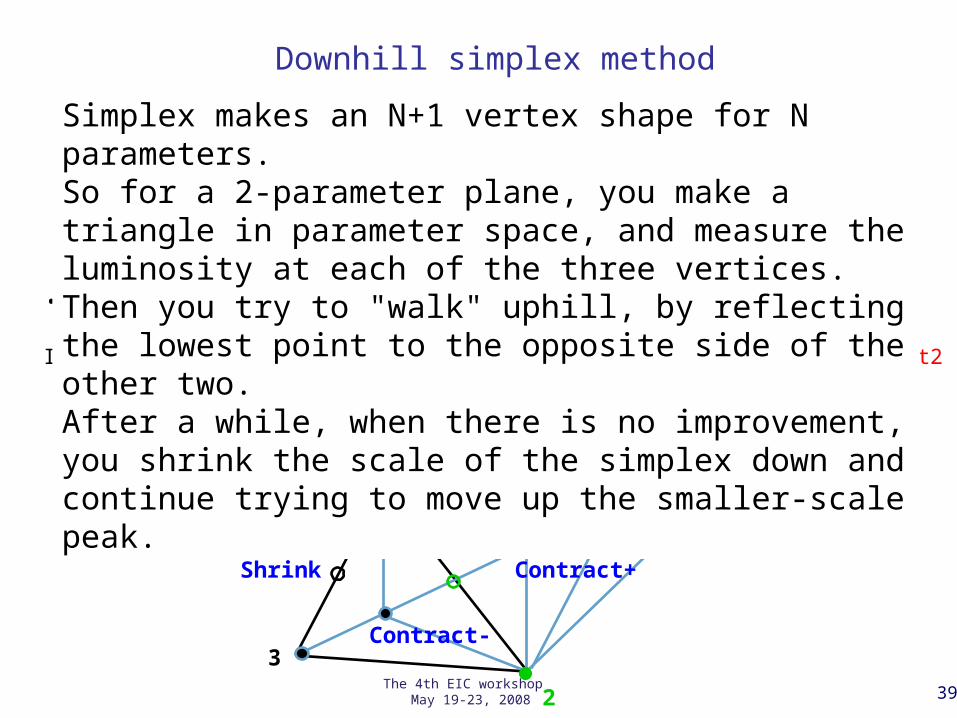
Downhill simplex method
Reflect
Expand
Contract+
Contract-
Shrink
1
2
3
Method of Minimization • {1, 2, 3} 1(best)<2(next-to-the worst)<3(worst)
• Evaluate 3R
• If 3R<1, • If 3E<3R, {1, 2, 3E} : Expand , if not, {1, 2, 3R} : Reflect
• If 1<3R<2, {1, 2, 3R} : Reflect• If 2<3R<3, Reflect 2 proposed by A. Hutton
• If 3C+<3R, {1, 2, 3C+} : Contract+ , if not, {1, 2, 3R} : Reflect• If 3<3R, Reflect 2
• If 3C-<3, {1, 2, 3C-} : Contract- , if not, {1, 2S, 3S} : Shrink/Reflect2
39
Simplex makes an N+1 vertex shape for N parameters. So for a 2-parameter plane, you make a triangle in parameter space, and measure the luminosity at each of the three vertices. Then you try to "walk" uphill, by reflecting the lowest point to the opposite side of the other two. After a while, when there is no improvement, you shrink the scale of the simplex down and continue trying to move up the smaller-scale peak.
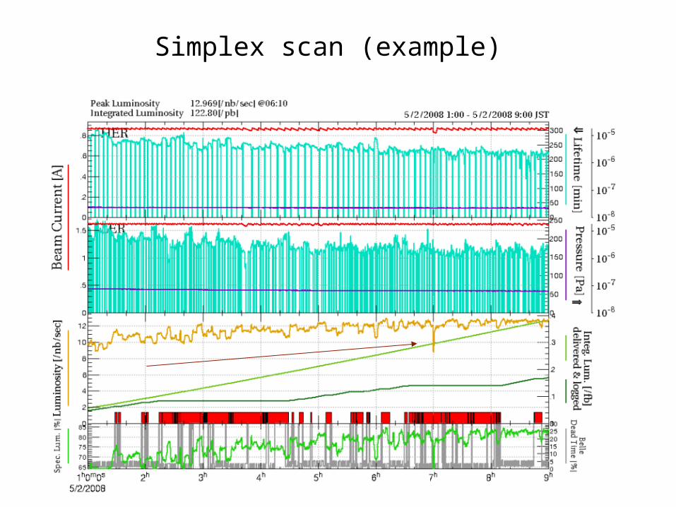
Simplex scan (example)
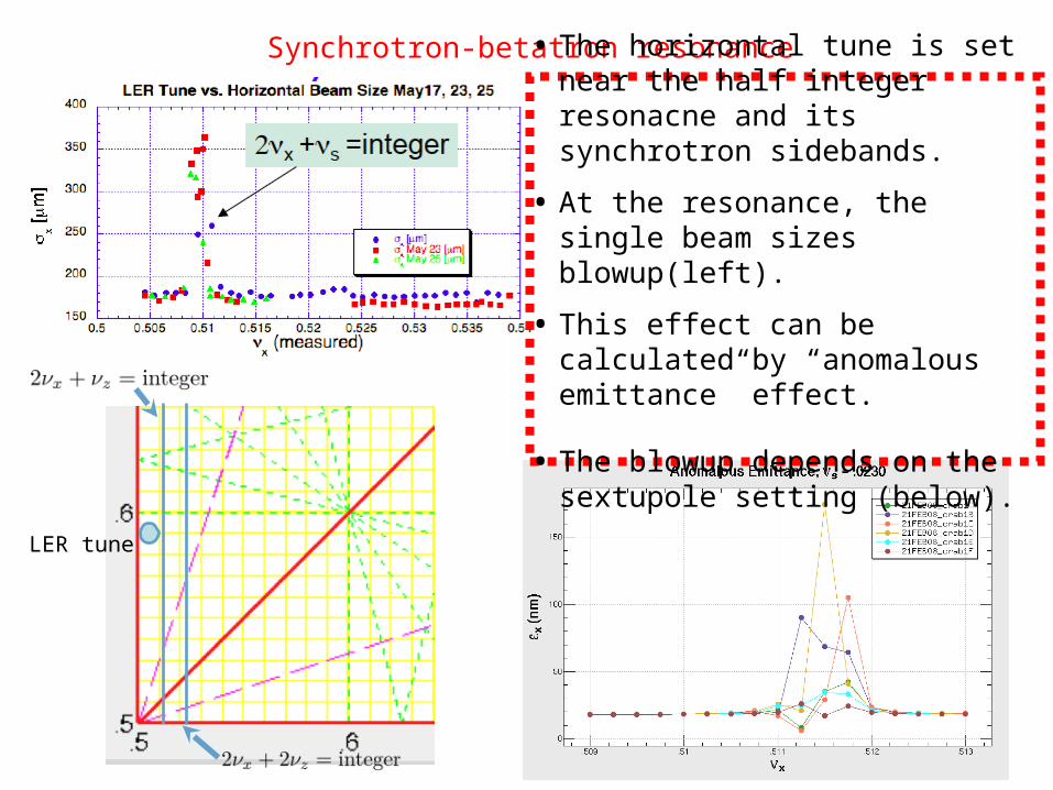
Synchrotron-betatron resonance
• The horizontal tune is set near the half integer resonacne and its synchrotron sidebands.
• At the resonance, the single beam sizes blowup(left).
• This effect can be calculated by “anomalous emittance” effect.
• The blowup depends on the sextupole setting (below).
LER tune
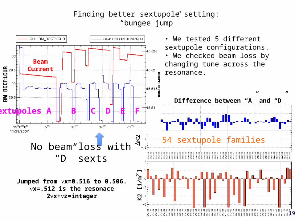
54 sextupole families
Sextupoles A B C D E F
Jumped from x=0.516 to 0.506.x=.512 is the resonace
2x+z=integer
BeamCurrent
Difference between “A” and “D”
• We tested 5 different sextupole configurations.• We checked beam loss by changing tune across the resonance.
Finding better sextupole setting: “bungee jump”
No beam loss with “D” sexts
19
Synchro-betatron resonance
• In many cases, the synchro-betatron resonance (2x + s = integer) limits the KEKB performance.– Beam size blowup, short lifetime, beam loss etc.
• The resonance is stronger in HER where no local chromaticity correction is installed.
• Strength of the resonance is strongly dependent a choice of sextupole setting.
• The resonance has something to do with the low specific luminosity at high bunch currents?
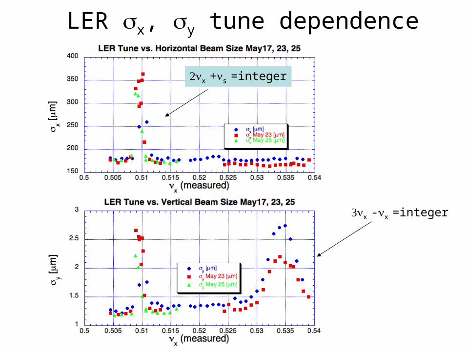
LER x, y tune dependence
x -x =integer
x +s =integer

Negative- Optics
• Motivation– To weaken the synchro-betatron resonance particularly in HER
– To shorten the bunch length
• Results– We have succeeded to weaken the synchro-betatron resonance line in
HER. We could operate the machine with x below the resonance line.– We have successfully shorten the bunch length of both beam.
• ~6mm -> ~4.5mm
– However, we found unexpectedly large synchrotron oscillation in LER and gave up the trial of the negative- optics.
2νx + νs = integer2νx + 2νs = integer
2νx - νs = integer2νx - 2νs = integer
νx: .5112, .5224with given νs ~ -.0224
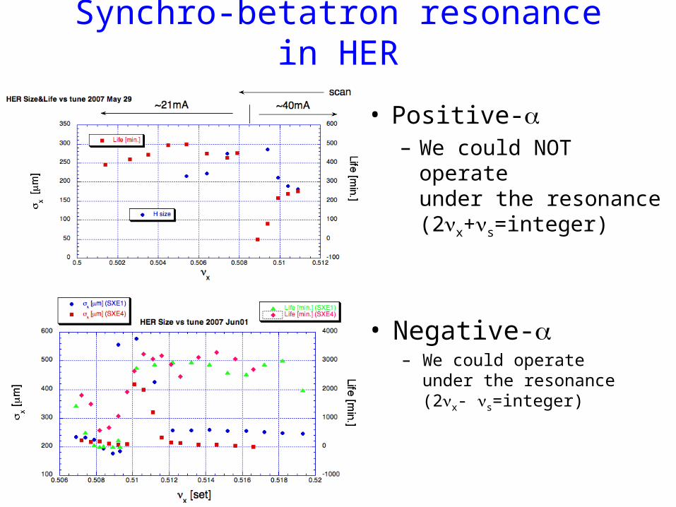
Synchro-betatron resonance in HER
• Positive-– We could NOT operate
under the resonance(2x+s=integer)
• Negative-– We could operate
under the resonance(2x- s=integer)
4. Summary
The 4th EIC workshop May 19-23, 2008

Crab Crossing Started at KEKB Two crab cavities were installed. Beam commissioning with crab crossing started in Feb.
2007. The effective head-on collision was confirmed by
streak camera crab-phase scan horizontal beam-beam kick, etc.
The highest vertical beam-beam tune-shift parameter is about 0.088 so far, which is higher than the geometrical gain due to head-on colliison by 15%. 16.1/nb/s was obtained yesterday.
There are a few speculated reasons for why the luminosity is lower than the prediction, but not yet confirmed.
We will do more study & machine tuning. Crab crossing is a must for SuperKEKB.
The 4th EIC workshop May 19-23, 2008
First in the worldFirst in the world

spare

The 4th EIC workshop May 19-23, 2008
Phase stability (histogram of phase detector signal)
HER LER0.007° 0.046°
Distribution of cavity phase (cavity feedback loops on)
Linear scale
Log scale
The tuner phase unstability was suppressed by low level RF control system.

Luminosity (estimated)
1350/700
1400/725
1500/775
1600/825
Beam currents1700/875 mA
3.5 buckets3x74x7 3.27
3x114x4
3.063x154x1
2.883x152x2
The specific luminosity is assumed to be on the line Green Ratio=1.

Crab Voltage Scan
4.6 mrad
y*
design
Oct. 13 100 bunches Nov. 19 1585 bunches
Lifetime
Luminosity
Lifetime
y*
Luminosity
The ratio of crab voltages was adjusted to give the same kick in both rings. The scan was done, keeping the voltage ratio.
The 4th EIC workshop May 19-23, 2008
LER HER
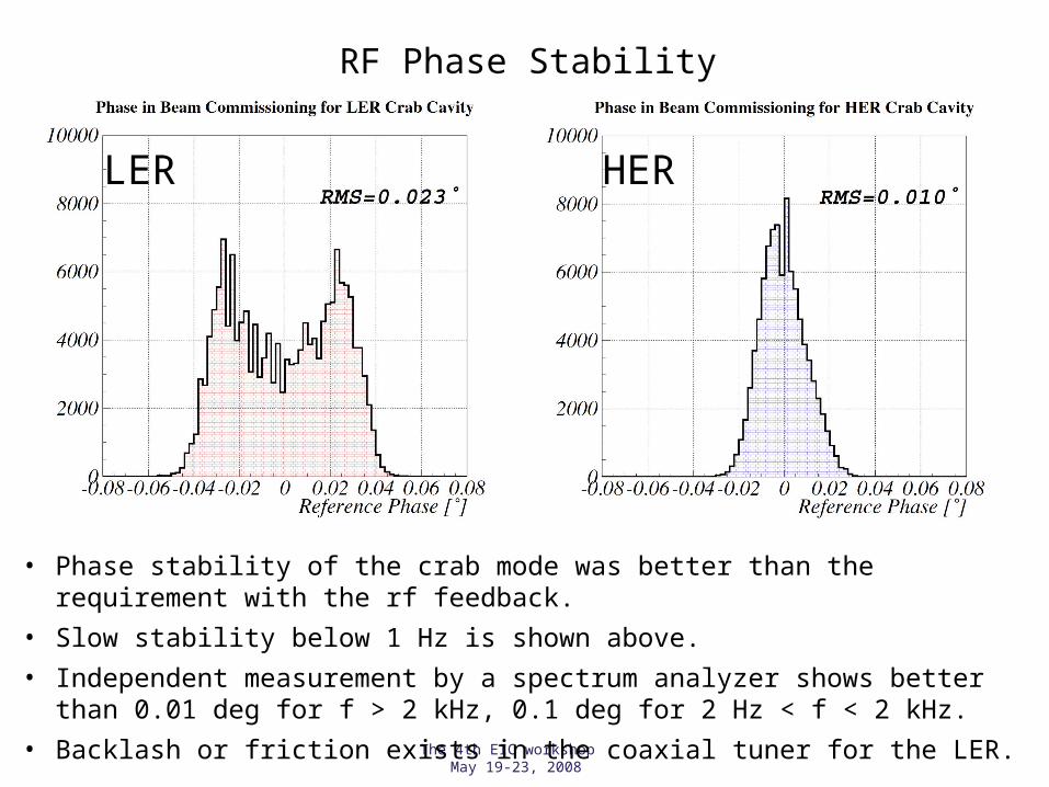
RF Phase Stability
• Phase stability of the crab mode was better than the requirement with the rf feedback.
• Slow stability below 1 Hz is shown above.
• Independent measurement by a spectrum analyzer shows better than 0.01 deg for f > 2 kHz, 0.1 deg for 2 Hz < f < 2 kHz.
• Backlash or friction exists in the coaxial tuner for the LER.

86
Phase stability
Span 200 kHzSideband peaks at 32kHz
and 64kHz.
Span 10 kHz Span 500 HzSideband peaks
at 32, 37, 46, 50, 100 Hz.
• Spectrum of pick up signal is consistent with phase detector data.
• Phase fluctuation faster than 1 kHz is less than ±0.01°, and slow fluctuation from ten to several hundreds of hertz is about ±0.1°.
• They are much less than the allowed phase error obtained from the beam-beam simulations for the crabbing beams in KEKB.
According to b-b simulation by Ohmi-san, allowed phase error for N-turn correlation is 0.1×√N (degree).
Spectrum around the crabbing mode measured at a pick up port of the LER crab cavity. Beam current was between 450 and 600 mA.
LER crab phase
HER crab phase
± 1 deg
Phase detector signal. Beam current was 385mA (HER) and 600 mA (LER).
K. Akai
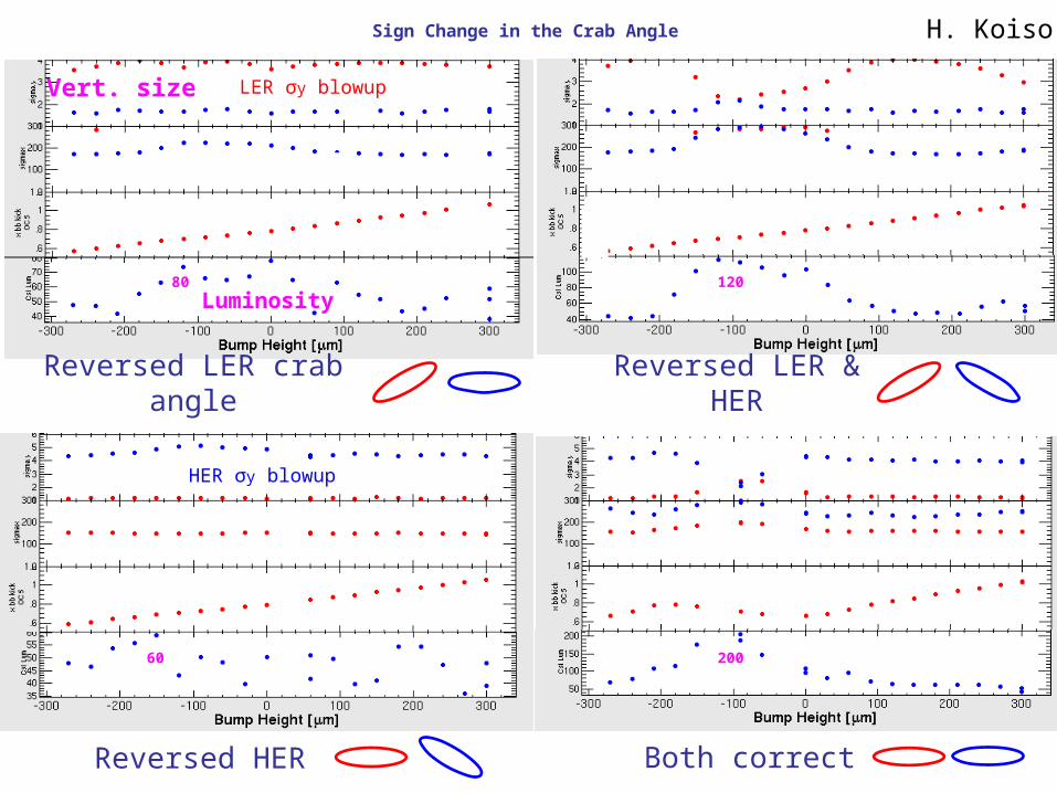
Sign Change in the Crab Angle
Luminosity
Vert. size LER σy blowup
12080
Reversed LER crab angle
Reversed LER & HER
Reversed HER
HER σy blowup
Both correct
20060
H. Koiso

The 4th EIC workshop May 19-23, 2008
Crossing angle
Transformation from lab. Frame
to head-on frame.
222
2*
**
**
**
*
**
11
tantan
sincos/
cos/
sin
cos/)tan(
]sin1[tan
yxzz
xzz
z
yy
x
xx
x
pppph
hppp
xhzz
pp
xhyy
hpp
xhzx
1000tan0
0cos/10000
00cos/1000
000100
0000cos/10
0tan0001
(: half crossing angle)
Linear part
Oide and Yokoya for storage rings (1989)
The 4th EIC workshop May 19-23, 2008
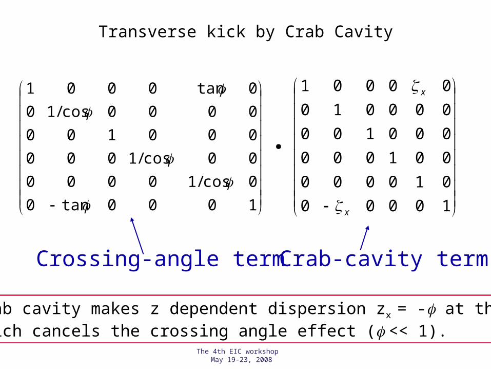
Transverse kick by Crab Cavity
10000
010000
001000
000100
000010
00001
x
x
Crab cavity makes z dependent dispersion zx = - at the IP, which cancels the crossing angle effect ( << 1).
1000tan0
0cos/10000
00cos/1000
000100
0000cos/10
0tan0001
.
Crossing-angle term Crab-cavity term

The 4th EIC workshop May 19-23, 2008
Crab-crossing simulation 0-mrad vs. 11-mrad crossing angle (K.Ohmi)
• Beam-beam limit is ~0.06 for 11 mrad half-crossing angle (both models agree well).
• 0-mrad (head-on) collision gives a higher y.• Beam-beam limit for 0-mrad crossing depends on the
model.
Weak-Strong model Strong-Strong model
Bunch current Bunch current