Embed Size (px)
Citation preview

THE__________________ NATIONAL___________ TESTING_____________ LABORATORIES______ LIMITED_____________ Established in 1923
199 Henlow Bay Winnipeg, MB R3Y 1G4
Phone (204) 488-6999 Fax (204) 488-6947
Email [email protected] www.nationaltestlabs.com
GEOTECHNICAL ENGINEERING • CONSTRUCTION MATERIALS TESTING
February 12, 2013 Stantec 100-1355 Taylor Avenue Winnipeg, Manitoba R3M 3Y9
Attention: Kevin Amy
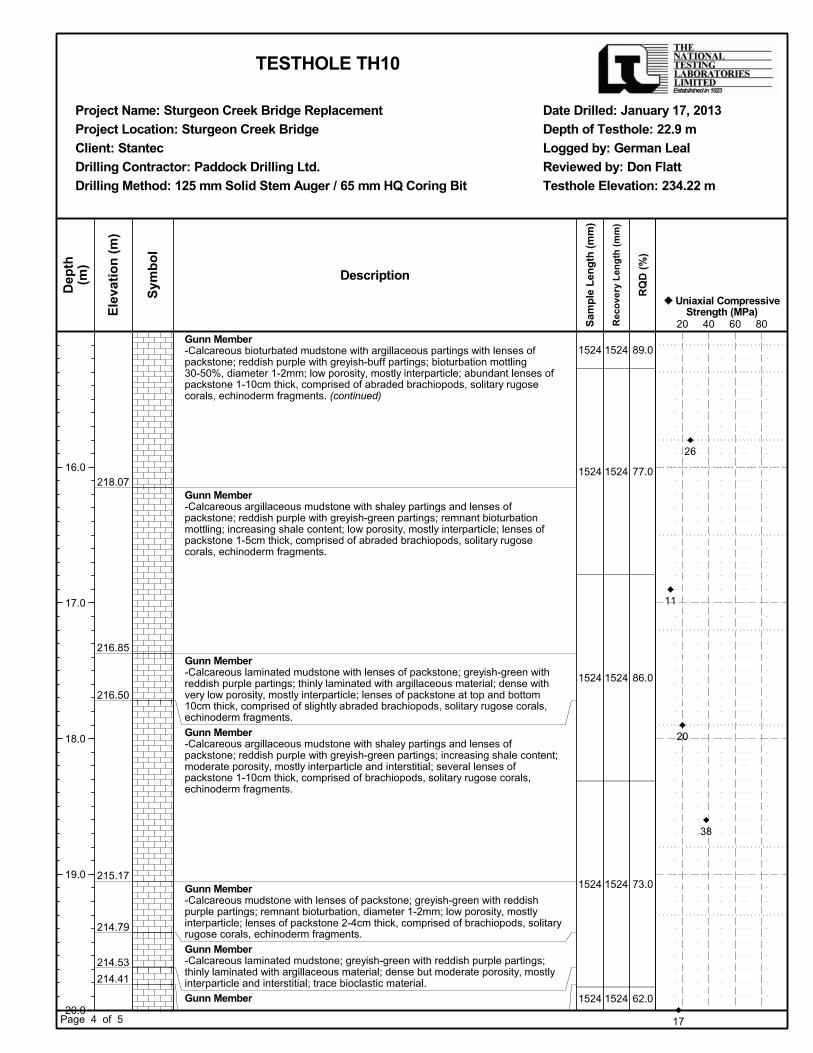
Kevin, Re: Sturgeon Road Bridge Replacement, Winnipeg, Manitoba The National Testing Laboratories Limited was retained to undertake a geotechnical investigation to verify the bedrock conditions for the proposed bridge structure for the southbound lanes on Sturgeon Road. The initial site investigation conducted in July 2010 revealed sound carbonate bedrock at the testhole locations. Based upon the quality of bedrock encountered in the testholes, shaft resistance values of 150 kPa (0 to 2.5 m below bedrock surface) and 1000 kPa (below 2.5 m) were provided for design of the rock-socketed caissons. During construction of the bridge structure for the northbound lanes, it was evident that the quality of bedrock encountered at the caisson locations was significantly lower than the quality of bedrock observed at the testhole locations. Based upon an evaluation of samples recovered from the caissons, an allowable shaft resistance of 300 kPa was provided for design of the caissons. Field Drilling Program On January 17, 2013, a testhole, identified as Testhole TH10, was drilled at the location of the south pier for the bridge structure for the southbound lanes. The testhole location is shown on the drawing provided in Appendix A. The testhole was drilled to auger refusal using a 125 mm diameter solid stem auger and then advanced 12 m into the underlying bedrock with a HQ coring bit. The core sample was returned to our laboratory for examination and testing. Laboratory Testing Samples of the bedrock core were selected and tested for uniaxial compressive strength (ASTM D7012) and point load strength index (ASTM D5731). The laboratory test reports are provided in Appendix B and the test data are summarized in the following tables.
Table 1 - Uniaxial Compressive Strength of Rock Cores (ASTM D7012) Sample Depth Below Existing Grade (m) Elevation (m) Uniaxial Compressive
Strength (MPa) 11.1 223.12 19 12.3 221.95 7 13.3 220.92 38 14.7 219.52 46 15.8 218.42 26 16.9 217.32 11 17.9 216.32 20 20.1 214.12 17

page 2 of 3
Table 2 – Point Load Strength Index of Rock Cores (ASTM D5731) Sample Depth Below Existing
Grade (m) Elevation (m)
Point Load Strength Index
(MPa)
Estimated Uniaxial Compressive
Strength (MPa)
18.6 215.62 1.67 38 18.7 215.52 1.53 38 21.4 212.82 0.91 21 21.5 212.72 0.60 15 21.6 212.62 0.69 17
The rock quality designation (RQD) of the bedrock core was determined in accordance with ASTM D6032. The RQD is defined as the total length of recovered core pieces greater than 100 mm in length expressed as a percentage of the core drilled. The RQD for the bedrock core is summarized in the following table.
Table 3 – RQD Test Data for Rock Cores (ASTM D6032) Top Elevation of Core Run
(m)
Length of Core Run
(m) RQD (%)
223.52 1.52 81 222.00 1.53 90 220.47 1.50 89 218.97 1.55 77 217.42 1.50 87 215.92 1.55 73 214.37 1.50 62 212.87 1.55 93
The RQD may be used as a general measure of rock quality. Based on the RQD values for the core samples, the bedrock quality is considered to be fair to excellent. SUBSURFACE CONDITIONS Soil Profile The typical stratigraphy at the site, as interpreted from the testhole log, consists of clay fill, clay and silt till underlain by calcareous mudstone. The testhole log is provided in Appendix C. Clay Fill Clay fill was encountered at the ground surface in the testhole. The clay fill extended to a depth approximately 2.8 m below the existing bridge deck. The clay fill contained gravel, sand and organic material. The clay fill was black, soft, moist, and of high plasticity. Clay Clay was encountered beneath the clay fill in the testhole. The clay was brown to grey, firm, moist, and of high plasticity.

Silt TillSilt till was encountered beneath the claydeck. The silt till was tan to red, loose to dense, moist, of low plasticity, and contained some sand and fine to coarse gravel. Athat boulders are present BedrockTesthole TH10 intercepts rocks of the Stony recovered from the testholePenitentmottled, calcareous mudstones of tlenses of packstoneincreases texture. Rock-Socketed CaissonsBased upon a review of the test data ansocketed caissonstherefore we recommend that the quality be neglected below the top of the bedrock.shaft resistance value is based upon socket lengths value is MPa for the rocktexture to improve bedrock can change significantly over short distances and actual bedrock quality at the caisson locations may differ from the bedrock quality observed in the core samples. If the actual bedrock quality is less than the quality assumed in the design of the caisson, the rock socket length must be increased to ensure the design capacity is achieved. Full time inspection by qualified geotechnical personnel is required to evaluate the bedrock quality and to make recommendations regarding any requirement for socket deepening.be used to confirm the quality of the Please this letter. Don Flatt, M. Eng., P.Eng.Senior Geotechnical Engineer
Silt Till Silt till was encountered beneath the claydeck. The silt till was tan to red, loose to dense, moist, of low plasticity, and contained some sand and fine to coarse gravel. Athat boulders are present
Bedrock Testhole TH10 intercepts rocks of the Stony recovered from the testholePenitentiary Member. mottled, calcareous mudstones of tlenses of packstoneincreases with increasing depthtexture. Photographs of the core sa
Socketed CaissonsBased upon a review of the test data ansocketed caissonstherefore we recommend that the quality at the surface of the bedrock mustbe neglected below the top of the bedrock.
resistance value is based upon socket lengths is also based upon
MPa for the rocktexture to improve bedrock can change significantly over short distances and actual bedrock quality at the caisson ocations may differ from the bedrock quality observed in the core samples. If the actual bedrock quality is less than the quality assumed in the design of the caisson, the rock socket length must be increased to ensure the design capacity is achieved.
ll time inspection by qualified geotechnical personnel is required to evaluate the bedrock quality and to make recommendations regarding any requirement for socket deepening.be used to confirm the quality of the
Please contact the undersignedetter.
Don Flatt, M. Eng., P.Eng.Senior Geotechnical Engineer
Silt till was encountered beneath the claydeck. The silt till was tan to red, loose to dense, moist, of low plasticity, and contained some sand and fine to coarse gravel. Athat boulders are present
Testhole TH10 intercepts rocks of the Stony recovered from the testhole
iary Member. mottled, calcareous mudstones of tlenses of packstone and
with increasing depthPhotographs of the core sa
Socketed CaissonsBased upon a review of the test data ansocketed caissons is 500 kPa. therefore we recommend that the
at the surface of the bedrock mustbe neglected below the top of the bedrock.
resistance value is based upon socket lengths based upon
MPa for the rock-socketed caissons. texture to improve bond between the bedrock and concretebedrock can change significantly over short distances and actual bedrock quality at the caisson ocations may differ from the bedrock quality observed in the core samples. If the actual bedrock quality is less than the quality assumed in the design of the caisson, the rock socket length must be increased to ensure the design capacity is achieved.
ll time inspection by qualified geotechnical personnel is required to evaluate the bedrock quality and to make recommendations regarding any requirement for socket deepening.be used to confirm the quality of the
contact the undersigned
Don Flatt, M. Eng., P.Eng.Senior Geotechnical Engineer
Silt till was encountered beneath the claydeck. The silt till was tan to red, loose to dense, moist, of low plasticity, and contained some sand and fine to coarse gravel. Although not encountered that boulders are present with
Testhole TH10 intercepts rocks of the Stony recovered from the testhole
iary Member. The remaining mottled, calcareous mudstones of t
and mudstonewith increasing depth
Photographs of the core sa
Socketed Caissons Based upon a review of the test data an
is 500 kPa. therefore we recommend that the
at the surface of the bedrock mustbe neglected below the top of the bedrock.
resistance value is based upon socket lengths based upon roughened sockets
socketed caissons. bond between the bedrock and concrete
bedrock can change significantly over short distances and actual bedrock quality at the caisson ocations may differ from the bedrock quality observed in the core samples. If the actual bedrock quality is less than the quality assumed in the design of the caisson, the rock socket length must be increased to ensure the design capacity is achieved.
ll time inspection by qualified geotechnical personnel is required to evaluate the bedrock quality and to make recommendations regarding any requirement for socket deepening.be used to confirm the quality of the
contact the undersigned
Don Flatt, M. Eng., P.Eng. Senior Geotechnical Engineer
Silt till was encountered beneath the claydeck. The silt till was tan to red, loose to dense, moist, of low plasticity, and contained some sand
lthough not encountered within the silt till in this area of Winnipeg.
Testhole TH10 intercepts rocks of the Stony is composed of calcareous bioturbated mudstones typical of the
The remaining mottled, calcareous mudstones of t
mudstone, and contains a considerable amount of clay. This clay content with increasing depth and is concentrated in lenses producing a fissile and friable
Photographs of the core samples are provided in Appendi
Based upon a review of the test data anis 500 kPa. The quality
therefore we recommend that the top 0.3 m be neglected in the design of the rock socketat the surface of the bedrock must
be neglected below the top of the bedrock.resistance value is based upon socket lengths
roughened socketssocketed caissons.
bond between the bedrock and concretebedrock can change significantly over short distances and actual bedrock quality at the caisson ocations may differ from the bedrock quality observed in the core samples. If the actual bedrock quality is less than the quality assumed in the design of the caisson, the rock socket length must be increased to ensure the design capacity is achieved.
ll time inspection by qualified geotechnical personnel is required to evaluate the bedrock quality and to make recommendations regarding any requirement for socket deepening.be used to confirm the quality of the rock
contact the undersigned if you have any questions regarding
Senior Geotechnical Engineer
Silt till was encountered beneath the clay at a depth of approximately 6deck. The silt till was tan to red, loose to dense, moist, of low plasticity, and contained some sand
lthough not encountered in the silt till in this area of Winnipeg.
Testhole TH10 intercepts rocks of the Stony is composed of calcareous bioturbated mudstones typical of the
The remaining 11 m of the rock coremottled, calcareous mudstones of the Gunn Member. The Gunn
and contains a considerable amount of clay. This clay content and is concentrated in lenses producing a fissile and friable mples are provided in Appendi
Based upon a review of the test data and rock cores, the allowable shaftThe quality of the bedrock was poor near the bedrock surface and
top 0.3 m be neglected in the design of the rock socketat the surface of the bedrock must be verified in the field to determine the actual length to
be neglected below the top of the bedrock. resistance value is based upon socket lengths
roughened socketssocketed caissons. Drilling/coring of the
bond between the bedrock and concretebedrock can change significantly over short distances and actual bedrock quality at the caisson ocations may differ from the bedrock quality observed in the core samples. If the actual bedrock quality is less than the quality assumed in the design of the caisson, the rock socket length must be increased to ensure the design capacity is achieved.
ll time inspection by qualified geotechnical personnel is required to evaluate the bedrock quality and to make recommendations regarding any requirement for socket deepening.
rock surface for each caiss
if you have any questions regarding
page 3 of
February 12,
at a depth of approximately 6deck. The silt till was tan to red, loose to dense, moist, of low plasticity, and contained some sand
lthough not encountered in the silt till in this area of Winnipeg.
Testhole TH10 intercepts rocks of the Stony Mountain Formation. The top 1.2 mis composed of calcareous bioturbated mudstones typical of the
11 m of the rock corehe Gunn Member. The Gunn
and contains a considerable amount of clay. This clay content and is concentrated in lenses producing a fissile and friable mples are provided in Appendi
d rock cores, the allowable shaftof the bedrock was poor near the bedrock surface and
top 0.3 m be neglected in the design of the rock socketbe verified in the field to determine the actual length to The quality of the rock decreases with depth
resistance value is based upon socket lengths roughened sockets and a minimum concrete compressive strength of 40
Drilling/coring of the bond between the bedrock and concrete
bedrock can change significantly over short distances and actual bedrock quality at the caisson ocations may differ from the bedrock quality observed in the core samples. If the actual bedrock quality is less than the quality assumed in the design of the caisson, the rock socket length must be increased to ensure the design capacity is achieved.
ll time inspection by qualified geotechnical personnel is required to evaluate the bedrock quality and to make recommendations regarding any requirement for socket deepening.
surface for each caiss
if you have any questions regarding
of 3
February 12, 2013
at a depth of approximately 6deck. The silt till was tan to red, loose to dense, moist, of low plasticity, and contained some sand
lthough not encountered at the testhole locationin the silt till in this area of Winnipeg.
Mountain Formation. The top 1.2 mis composed of calcareous bioturbated mudstones typical of the
11 m of the rock core he Gunn Member. The Gunn
and contains a considerable amount of clay. This clay content and is concentrated in lenses producing a fissile and friable mples are provided in Appendi
d rock cores, the allowable shaftof the bedrock was poor near the bedrock surface and
top 0.3 m be neglected in the design of the rock socketbe verified in the field to determine the actual length to
The quality of the rock decreases with depth resistance value is based upon socket lengths that do not exceed
a minimum concrete compressive strength of 40 Drilling/coring of the bed
bond between the bedrock and concretebedrock can change significantly over short distances and actual bedrock quality at the caisson ocations may differ from the bedrock quality observed in the core samples. If the actual bedrock quality is less than the quality assumed in the design of the caisson, the rock socket length must be increased to ensure the design capacity is achieved.
ll time inspection by qualified geotechnical personnel is required to evaluate the bedrock quality and to make recommendations regarding any requirement for socket deepening.
surface for each caiss
if you have any questions regarding
at a depth of approximately 6deck. The silt till was tan to red, loose to dense, moist, of low plasticity, and contained some sand
at the testhole locationin the silt till in this area of Winnipeg.
Mountain Formation. The top 1.2 mis composed of calcareous bioturbated mudstones typical of the
is composed of reddishhe Gunn Member. The Gunn
and contains a considerable amount of clay. This clay content and is concentrated in lenses producing a fissile and friable mples are provided in Appendix D
d rock cores, the allowable shaftof the bedrock was poor near the bedrock surface and
top 0.3 m be neglected in the design of the rock socketbe verified in the field to determine the actual length to
The quality of the rock decreases with depth that do not exceed
a minimum concrete compressive strength of 40 bedrock should provide a rough surface
bond between the bedrock and concrete. It should be noted that the quality of bedrock can change significantly over short distances and actual bedrock quality at the caisson ocations may differ from the bedrock quality observed in the core samples. If the actual bedrock quality is less than the quality assumed in the design of the caisson, the rock socket length must be
ll time inspection by qualified geotechnical personnel is required to evaluate the bedrock quality and to make recommendations regarding any requirement for socket deepening.
surface for each caisson prior to concrete placement
if you have any questions regarding
at a depth of approximately 6 m below the existing bridge deck. The silt till was tan to red, loose to dense, moist, of low plasticity, and contained some sand
at the testhole locationin the silt till in this area of Winnipeg.
Mountain Formation. The top 1.2 mis composed of calcareous bioturbated mudstones typical of the
is composed of reddishhe Gunn Member. The Gunn Member is i
and contains a considerable amount of clay. This clay content and is concentrated in lenses producing a fissile and friable
x D.
d rock cores, the allowable shaft resistance valueof the bedrock was poor near the bedrock surface and
top 0.3 m be neglected in the design of the rock socketbe verified in the field to determine the actual length to
The quality of the rock decreases with depth that do not exceed 6
a minimum concrete compressive strength of 40 rock should provide a rough surface It should be noted that the quality of
bedrock can change significantly over short distances and actual bedrock quality at the caisson ocations may differ from the bedrock quality observed in the core samples. If the actual bedrock quality is less than the quality assumed in the design of the caisson, the rock socket length must be
ll time inspection by qualified geotechnical personnel is required to evaluate the bedrock quality and to make recommendations regarding any requirement for socket deepening.
on prior to concrete placement
if you have any questions regarding the information provided in
m below the existing bridge deck. The silt till was tan to red, loose to dense, moist, of low plasticity, and contained some sand
at the testhole location, it has been reported
Mountain Formation. The top 1.2 mis composed of calcareous bioturbated mudstones typical of the
is composed of reddishember is i
and contains a considerable amount of clay. This clay content and is concentrated in lenses producing a fissile and friable
resistance valueof the bedrock was poor near the bedrock surface and
top 0.3 m be neglected in the design of the rock socketbe verified in the field to determine the actual length to
The quality of the rock decreases with depth 6 m. The shaft resistance
a minimum concrete compressive strength of 40 rock should provide a rough surface It should be noted that the quality of
bedrock can change significantly over short distances and actual bedrock quality at the caisson ocations may differ from the bedrock quality observed in the core samples. If the actual bedrock quality is less than the quality assumed in the design of the caisson, the rock socket length must be
ll time inspection by qualified geotechnical personnel is required to evaluate the bedrock quality and to make recommendations regarding any requirement for socket deepening.
on prior to concrete placement
the information provided in
m below the existing bridge deck. The silt till was tan to red, loose to dense, moist, of low plasticity, and contained some sand
has been reported
Mountain Formation. The top 1.2 m of the is composed of calcareous bioturbated mudstones typical of the
is composed of reddish-purple, burrowember is interbedde
and contains a considerable amount of clay. This clay content and is concentrated in lenses producing a fissile and friable
resistance valueof the bedrock was poor near the bedrock surface and
top 0.3 m be neglected in the design of the rock socket. Tbe verified in the field to determine the actual length to
The quality of the rock decreases with depth The shaft resistance
a minimum concrete compressive strength of 40 rock should provide a rough surface It should be noted that the quality of
bedrock can change significantly over short distances and actual bedrock quality at the caisson ocations may differ from the bedrock quality observed in the core samples. If the actual bedrock quality is less than the quality assumed in the design of the caisson, the rock socket length must be
ll time inspection by qualified geotechnical personnel is required to evaluate the bedrock quality A camera should
on prior to concrete placement
the information provided in
m below the existing bridge deck. The silt till was tan to red, loose to dense, moist, of low plasticity, and contained some sand
has been reported
of the rock core is composed of calcareous bioturbated mudstones typical of the
purple, burrownterbedded with
and contains a considerable amount of clay. This clay content and is concentrated in lenses producing a fissile and friable
resistance value for rockof the bedrock was poor near the bedrock surface and
. The rock be verified in the field to determine the actual length to
The quality of the rock decreases with depth and the The shaft resistance
a minimum concrete compressive strength of 40 rock should provide a rough surface It should be noted that the quality of
bedrock can change significantly over short distances and actual bedrock quality at the caisson ocations may differ from the bedrock quality observed in the core samples. If the actual bedrock quality is less than the quality assumed in the design of the caisson, the rock socket length must be
ll time inspection by qualified geotechnical personnel is required to evaluate the bedrock quality A camera should
on prior to concrete placement.
the information provided in
m below the existing bridge deck. The silt till was tan to red, loose to dense, moist, of low plasticity, and contained some sand
has been reported
rock core is composed of calcareous bioturbated mudstones typical of the
purple, burrow-d with
and contains a considerable amount of clay. This clay content and is concentrated in lenses producing a fissile and friable
for rock-of the bedrock was poor near the bedrock surface and
he rock be verified in the field to determine the actual length to
and the The shaft resistance
a minimum concrete compressive strength of 40 rock should provide a rough surface It should be noted that the quality of
bedrock can change significantly over short distances and actual bedrock quality at the caisson ocations may differ from the bedrock quality observed in the core samples. If the actual bedrock quality is less than the quality assumed in the design of the caisson, the rock socket length must be
ll time inspection by qualified geotechnical personnel is required to evaluate the bedrock quality A camera should
the information provided in

APPENDIX A
TESTHOLE LOCATION PLAN

ORIGINALSEALED BY
P. ENG.K. S. AMY
12.03.26

APPENDIX B
LABORATORY TEST REPORTS

Project Project ProjectName Location Number
Testhole 1 Depth 36.5' - 37.7' Area (mm²) 3142 L (mm) 133.25 D (mm) 63.25
AxialTolerance Min Max D1 D2 D3 D4
L1 0.000 0.006 0.000 0.000 0.000 0.000 D1 0.001L2 0.000 0.008 0.001 0.004 0.002 0.005 D2 0.004L3 0.000 0.009 D3 0.002
D4 0.005L1
L2 L/D Ratio 2.1L3
0.0050.002
Load, kN 59.9 19Tested By MVG Date
Project Project ProjectName Location Number
Testhole 1 Depth 43.6' - 44.3' Area (mm²) 3142 L (mm) 151.75 D (mm) 63.25
AxialTolerance Min Max D1 D2 D3 D4
L1 0.000 0.011 0.000 0.000 0.000 0.000 D1 0.005L2 0.000 0.009 0.005 0.007 0.006 0.006 D2 0.007L3 0.000 0.010 D3 0.006
D4 0.006L1
L2 L/D Ratio 2.4L3
0.0070.003
Load, kN 120.9 38Tested By MVG Date
COMPRESSIVE STRENGTH of INTACT ROCK CORE ASTM D 7012Compressive Strength, MPa Unit Weight, g/cm³ 2.411
Jan.25.2013 Remarks
0.010 L/D Meets Spec
Maximum Axial Deviation (in)
0.011Perpendicularity Meets
SpecAxial Deviation Meets Spec
0.0110.009
Axial End Surface Flatness PerpendicularityTolerance
Stantec Ltd.ROCK CORE DIMENSIONAL and SHAPE TOLERANCES ASTM D 4543
Sturgeon Creek Bridge Winnipeg 121615644
COMPRESSIVE STRENGTH of INTACT ROCK CORE ASTM D 7012Compressive Strength, MPa Unit Weight, g/cm³ 2.310
Jan.25.2013 Remarks
0.009 L/D Meets Spec
Maximum Axial Deviation (in)
0.009Perpendicularity Meets
SpecAxial Deviation Meets Spec
0.0060.008
Axial End Surface Flatness PerpendicularityTolerance
Stantec Ltd.ROCK CORE DIMENSIONAL and SHAPE TOLERANCES ASTM D 4543
Sturgeon Creek Bridge Winnipeg 121615644

Project Project ProjectName Location Number
Testhole 1 Depth 40.3' - 40.9' Area (mm²) 3142 L (mm) 94.00 D (mm) 63.25
AxialTolerance Min Max D1 D2 D3 D4
L1 0.000 0.009 0.000 0.000 0.000 0.000 D1 0.005L2 0.000 0.007 0.005 0.007 0.004 0.005 D2 0.007L3 0.000 0.009 D3 0.004
D4 0.005L1
L2 L/D Ratio 1.5L3
0.0070.003
Load, kN 22.4 7Tested By MVG Date
Project Project ProjectName Location Number
Testhole 1 Depth 55.4' - 56.2' Area (mm²) 3167 L (mm) 101.00 D (mm) 63.50
AxialTolerance Min Max D1 D2 D3 D4
L1 0.000 0.007 0.000 0.000 0.000 0.000 D1 0.004L2 0.000 0.007 0.004 0.007 0.006 0.007 D2 0.007L3 0.000 0.008 D3 0.006
D4 0.007L1
L2 L/D Ratio 1.6L3
0.007
0.003
Load, kN 36.3 11Tested By MVG Date
Stantec Ltd.ROCK CORE DIMENSIONAL and SHAPE TOLERANCES ASTM D 4543
Sturgeon Creek Bridge Winnipeg 121615644
Axial End Surface Flatness PerpendicularityTolerance
0.0090.0070.009 L/D Out of Spec
Maximum Axial Deviation (in)
0.009Perpendicularity Meets
SpecAxial Deviation Meets Spec
COMPRESSIVE STRENGTH of INTACT ROCK CORE ASTM D 7012Compressive Strength, MPa Unit Weight, g/cm³ 2.371
Jan.25.2013 Remarks L/D Ratio does not meet specifications
Stantec Ltd.ROCK CORE DIMENSIONAL and SHAPE TOLERANCES ASTM D 4543
Sturgeon Creek Bridge Winnipeg 121615644
Axial End Surface Flatness PerpendicularityTolerance
0.0070.0070.008 L/D Out of Spec
Maximum Axial Deviation (in)
0.008Perpendicularity Meets
SpecAxial Deviation Meets Spec
COMPRESSIVE STRENGTH of INTACT ROCK CORE ASTM D 7012Compressive Strength, MPa Unit Weight, g/cm³ 2.398
Jan.25.2013 Remarks L/D Ratio does not meet specifications

Project Project ProjectName Location Number
Testhole 1 Depth 48.3' - 49.1' Area (mm²) 3142 L (mm) 147.25 D (mm) 63.25
AxialTolerance Min Max D1 D2 D3 D4
L1 0.000 0.006 0.000 0.000 0.000 0.000 D1 0.009L2 0.000 0.004 0.009 0.007 0.007 0.006 D2 0.007L3 0.000 0.008 D3 0.007
D4 0.006L1
L2 L/D Ratio 2.3L3
0.0090.004
Load, kN 144.4 46Tested By MVG Date
Project Project ProjectName Location Number
Testhole 1 Depth 51.8' - 52.9' Area (mm²) 3142 L (mm) 138.25 D (mm) 63.25
AxialTolerance Min Max D1 D2 D3 D4
L1 0.000 0.009 0.000 0.000 0.000 0.000 D1 0.006L2 0.000 0.008 0.006 0.007 0.006 0.008 D2 0.007L3 0.000 0.009 D3 0.006
D4 0.008L1
L2 L/D Ratio 2.2L3
0.0080.003
Load, kN 82.7 26Tested By MVG Date
Stantec Ltd.ROCK CORE DIMENSIONAL and SHAPE TOLERANCES ASTM D 4543
Sturgeon Creek Bridge Winnipeg 121615644
Axial End Surface Flatness PerpendicularityTolerance
0.0060.0040.008 L/D Meets Spec
Maximum Axial Deviation (in)
0.008Perpendicularity Meets
SpecAxial Deviation Meets Spec
COMPRESSIVE STRENGTH of INTACT ROCK CORE ASTM D 7012Compressive Strength, MPa Unit Weight, g/cm³ 2.544
Jan.25.2013 Remarks
Stantec Ltd.ROCK CORE DIMENSIONAL and SHAPE TOLERANCES ASTM D 4543
Sturgeon Creek Bridge Winnipeg 121615644
Axial End Surface Flatness PerpendicularityTolerance
0.0090.0080.009 L/D Meets Spec
Maximum Axial Deviation (in)
0.009Perpendicularity Meets
SpecAxial Deviation Meets Spec
COMPRESSIVE STRENGTH of INTACT ROCK CORE ASTM D 7012Compressive Strength, MPa Unit Weight, g/cm³ 2.490
Jan.25.2013 Remarks

Project Project ProjectName Location Number
Testhole 1 Depth 58.6' - 59.6' Area (mm²) 3142 L (mm) 132.50 D (mm) 63.25
AxialTolerance Min Max D1 D2 D3 D4
L1 0.000 0.008 0.000 0.000 0.000 0.000 D1 0.005L2 0.000 0.009 0.005 0.007 0.006 0.008 D2 0.007L3 0.000 0.007 D3 0.006
D4 0.008L1
L2 L/D Ratio 2.1L3
0.0080.003
Load, kN 63.7 20Tested By MVG Date
Project Project ProjectName Location Number
Testhole 1 Depth 65.8' - 66.5' Area (mm²) 3142 L (mm) 133.00 D (mm) 63.25
AxialTolerance Min Max D1 D2 D3 D4
L1 0.000 0.006 0.000 0.000 0.000 0.000 D1 0.007L2 0.000 0.007 0.007 0.008 0.006 0.006 D2 0.008L3 0.000 0.007 D3 0.006
D4 0.006L1
L2 L/D Ratio 2.1L3
0.0080.003
Load, kN 53.2 17Tested By MVG Date
Stantec Ltd.ROCK CORE DIMENSIONAL and SHAPE TOLERANCES ASTM D 4543
Sturgeon Creek Bridge Winnipeg 121615644
Axial End Surface Flatness PerpendicularityTolerance
0.0080.0090.007 L/D Meets Spec
Maximum Axial Deviation (in)
0.009Perpendicularity Meets
SpecAxial Deviation Meets Spec
COMPRESSIVE STRENGTH of INTACT ROCK CORE ASTM D 7012Compressive Strength, MPa Unit Weight, g/cm³ 2.397
Jan.25.2013 Remarks
Stantec Ltd.ROCK CORE DIMENSIONAL and SHAPE TOLERANCES ASTM D 4543
Sturgeon Creek Bridge Winnipeg 121615644
Axial End Surface Flatness PerpendicularityTolerance
0.0060.0070.007 L/D Meets Spec
Maximum Axial Deviation (in)
0.007Perpendicularity Meets
SpecAxial Deviation Meets Spec
COMPRESSIVE STRENGTH of INTACT ROCK CORE ASTM D 7012Compressive Strength, MPa Unit Weight, g/cm³ 2.374
Jan.25.2013 Remarks

Project Project ProjectName Location No.
* Indicate Type of Test Using D for Diametral, A for Axial and B for Block Sample Entry of Length is required for Type A and B only.
Type of Diam. Length Load Pt. Load IS(50) Inferred
From To Test D (mm) L (mm) P (kN) Is (MPa) (MPa) QU (MPa)
1 61.0' 61.1' A 63.4 32.1 4.3 1.66 1.67 38 Tested perp. To bedding1 61.1' 61.2' A 63.3 44.9 5.1 1.41 1.53 38 Tested perp. To bedding
1 70.4' 70.5' A 63.3 31.6 2.3 0.90 0.91 21 Tested perp. To bedding1 70.5' 70.6' A 63.3 44.6 2.0 0.56 0.60 15 Tested perp. To bedding1 70.6' 70.7' A 63.3 39.7 2.1 0.66 0.69 17 Tested perp. To bedding
Tested By Date Checked By Date
RemarksDepth Interval
Testhole
Jan. 25, 2013M. Glawson
STANTEC CONSULTING LTD.
POINT LOAD STRENGTH INDEX121615644WinnipegSturgeon Creek Bridge
ISO 9001 FORM GEO03

APPENDIX C
TESTHOLE LOG


APPENDIX D
BEDROCK CORE PHOTOGRAPHS

Photo 1 – TH1 from 10.67 m to 13.72 m (Elev. 223.52 to 220.47 m)
223.52 m 222.00 m
220.47 m 222.00 m

Photo 2 – TH1 from 13.72 m to 16.77 m (Elev. 220.47 to 217.42 m)
218.97 m 220.47 m
217.42 m 218.97 m

Photo Photo 3 – TH1 from TH1 from 16.77
217.42 m
215.92 m
16.77 m to
217.42 m
215.92 m
m to 19.82
19.82 m (Elev.
214.37 m
m (Elev. 217.42
215.92 m
214.37 m
217.42 to 214.37
215.92 m
214.37 m)m)

Photo 4 – TH1 from 19.82 m to 22.87 m (Elev. 214.37 to 211.32 m)
212.87 m 214.37 m
211.32 m 212.87 m